EP1758004A2 - NC Machine Tool - Google Patents
NC Machine Tool Download PDFInfo
- Publication number
- EP1758004A2 EP1758004A2 EP06119539A EP06119539A EP1758004A2 EP 1758004 A2 EP1758004 A2 EP 1758004A2 EP 06119539 A EP06119539 A EP 06119539A EP 06119539 A EP06119539 A EP 06119539A EP 1758004 A2 EP1758004 A2 EP 1758004A2
- Authority
- EP
- European Patent Office
- Prior art keywords
- tool
- data
- control unit
- history
- machine tool
- Prior art date
- Legal status (The legal status is an assumption and is not a legal conclusion. Google has not performed a legal analysis and makes no representation as to the accuracy of the status listed.)
- Granted
Links
Images


Classifications
-
- G—PHYSICS
- G05—CONTROLLING; REGULATING
- G05B—CONTROL OR REGULATING SYSTEMS IN GENERAL; FUNCTIONAL ELEMENTS OF SUCH SYSTEMS; MONITORING OR TESTING ARRANGEMENTS FOR SUCH SYSTEMS OR ELEMENTS
- G05B19/00—Program-control systems
- G05B19/02—Program-control systems electric
- G05B19/18—Numerical control [NC], i.e. automatically operating machines, in particular machine tools, e.g. in a manufacturing environment, so as to execute positioning, movement or co-ordinated operations by means of program data in numerical form
- G05B19/4093—Numerical control [NC], i.e. automatically operating machines, in particular machine tools, e.g. in a manufacturing environment, so as to execute positioning, movement or co-ordinated operations by means of program data in numerical form characterised by part programming, e.g. entry of geometrical information as taken from a technical drawing, combining this with machining and material information to obtain control information, named part program, for the NC machine
- G05B19/40937—Numerical control [NC], i.e. automatically operating machines, in particular machine tools, e.g. in a manufacturing environment, so as to execute positioning, movement or co-ordinated operations by means of program data in numerical form characterised by part programming, e.g. entry of geometrical information as taken from a technical drawing, combining this with machining and material information to obtain control information, named part program, for the NC machine concerning programming of machining or material parameters, pocket machining
- G05B19/40938—Tool management
-
- G—PHYSICS
- G05—CONTROLLING; REGULATING
- G05B—CONTROL OR REGULATING SYSTEMS IN GENERAL; FUNCTIONAL ELEMENTS OF SUCH SYSTEMS; MONITORING OR TESTING ARRANGEMENTS FOR SUCH SYSTEMS OR ELEMENTS
- G05B2219/00—Program-control systems
- G05B2219/30—Nc systems
- G05B2219/34—Director, elements to supervisory
- G05B2219/34393—Stop program if needed workpiece, tool or data lacks, misses
-
- G—PHYSICS
- G05—CONTROLLING; REGULATING
- G05B—CONTROL OR REGULATING SYSTEMS IN GENERAL; FUNCTIONAL ELEMENTS OF SUCH SYSTEMS; MONITORING OR TESTING ARRANGEMENTS FOR SUCH SYSTEMS OR ELEMENTS
- G05B2219/00—Program-control systems
- G05B2219/30—Nc systems
- G05B2219/50—Machine tool, machine tool null till machine tool work handling
- G05B2219/50245—Change tools, like laser head and drill having different driving needs
-
- Y—GENERAL TAGGING OF NEW TECHNOLOGICAL DEVELOPMENTS; GENERAL TAGGING OF CROSS-SECTIONAL TECHNOLOGIES SPANNING OVER SEVERAL SECTIONS OF THE IPC; TECHNICAL SUBJECTS COVERED BY FORMER USPC CROSS-REFERENCE ART COLLECTIONS [XRACs] AND DIGESTS
- Y02—TECHNOLOGIES OR APPLICATIONS FOR MITIGATION OR ADAPTATION AGAINST CLIMATE CHANGE
- Y02P—CLIMATE CHANGE MITIGATION TECHNOLOGIES IN THE PRODUCTION OR PROCESSING OF GOODS
- Y02P90/00—Enabling technologies with a potential contribution to greenhouse gas [GHG] emissions mitigation
- Y02P90/02—Total factory control, e.g. smart factories, flexible manufacturing systems [FMS] or integrated manufacturing systems [IMS]
Definitions
- the present invention relates to an NC machine tool, in particular, an NC machine tool capable of preventing a tool exchange error by the operator.
- Japanese Laid-Open Patent Publication No. 11-33867 discloses a technique of detecting change of a machining program, tool exchange, change of data correction amount by sensors, in preparation for the case where the tool interferes with a machine, and decreasing rapid transverse speed of the tool to perform automatic operation of a machine tool.
- the technique serves to reduce damage caused by interference of the tool with the machine, not to prevent occurrence of a tool exchange error. For this reason, even when damage due to interference of the tool with the machine is suppressed, both of the tool and the machine can be damaged or operation of the machine tool can be stopped, resulting in a decrease in productivity.
- Japanese Laid-Open Patent Publication No. 07-223148 proposes a technique of preventing an accident caused by a tool exchange error. According to the technique, at automatic operation of the NC machine tool, it is determined whether a correct tool is actually attached by detecting the shape of the attached tool by use of an optical sensor. However the technique has the disadvantage that it takes cost to construct a structure for recognizing the shape of the tool and determining the tool exchange error.
- An objective of the present invention is to provide an NC machine tool capable of preventing a tool exchange error by drawing an attention of the operator on the basis of internal data of a machine tool.
- an NC machine tool that moves a head, to which a tool is attached, and a work relative to each other, thereby machining the work with the tool.
- the NC machine tool includes exchange history storage means, data storage means, update history storage means, determination means, control means, and alarm means.
- the exchange history storage means stores, when the tool has been manually exchanged, history of the exchange.
- the data storage means stores data on the tool.
- the update history storage means stores, when the data is updated, history of the update.
- the determination means determines whether there has been a change related to the tool on the basis of the exchange history and the update history.
- the control means stops movement of the tool on the basis of a determination result of the determination means.
- the alarm means issues an alarm about the tool on the basis of the determination result of the determination means.
- a machining center 1 has a main unit 2.
- a table 3 is supported by the main unit 2 so as to be movable in a horizontal direction (X-axis direction, Y-axis direction).
- a column 2a of the main unit 2 is provided with a spindle head 5.
- the spindle head 5 is disposed above the table 3.
- the spindle head 5 is supported so as to be movable in a vertical direction (Z-axis direction) with respect to the table 3.
- the table 3 and the spindle head 5 are held in the machining center 1 so as to be relatively movable along three axes (X, Y, Z), all perpendicular to one another.
- the amount of movement of the table 3 and the spindle head 5 is controlled by an NC device 100 and a work set on the table 3 is machined by use of a tool K attached to the spindle head 5.
- the tool K can be attached/detached to/from a spindle 5a of the spindle head 5.
- a tool exchanger 6 is formed on a side of the spindle head 5.
- a disc-like tool magazine 7 is rotatably supported by the main unit 2.
- On a periphery of the tool magazine 7 are arranged a plurality of pockets 7a for accommodating tools 9.
- the tools 9 can be attached/detached to/from the pockets 7a.
- a cylindrical cover 2b which covers a circumference of the tool magazine 7 is formed on the main unit 2.
- a tool picking port 2c is formed on the cover 2b. The tool picking port 2c corresponds to a tool picking position A.
- each tool pocket 7a is disposed at the tool picking position A.
- the operator can manually exchange the tool in the tool pocket 7a disposed at the tool picking position A.
- a sensor 40 as a detector for detecting the presence or absence of the tool 9 in each tool pocket 7a is provided at the tool picking position A in the tool magazine 7.
- the sensor 40 is connected to a main control unit 130 of the NC device 100 (refer to Fig. 5) and a signal output from the sensor 40 is read by the main control unit 130. When the output signal from the sensor 40 is changed from OFF to ON, the main control unit 130 determines that the tool has been manually exchanged.
- a unique pocket number "TNo.” is given to each tool pocket 7a in the tool magazine 7.
- the spare tools 9 are located in the tool magazine 7.
- the tool exchanger 6 has a rotational arm 6a which protrudes downward and a holder 6b is rotatably supported by a lower end of the rotational arm 6a.
- the rotational arm 6a rotates, the tool K attached to the spindle 5a is replaced by the tool 9 held by the holder 6b.
- the tools 9 in the tool pockets 7a such as an end mill and a drill, are consecutively disposed at the tool picking position A.
- the NC device 100 has an input unit 110 including a keyboard, a display unit 120 including a display device such as liquid crystal display and an alarm device, the main control unit 130 as a controller, various memories 150 to 170, a machining control unit 200 and a tool exchange control unit 300.
- the main control unit 130 is connected to the input unit 110, the display unit 120, the various memories 150 to 170, the machining control unit 200 and the tool exchange control unit 300 via a bus 140.
- a machining program memory 150 stores a machining program for machining a work.
- a data memory 160 as a data storage means stores data on the tool used in the machining center 1 (hereinafter referred to as tool data) therein.
- the tool data includes TNo., tool name, diameter, suffix, tool diameter, tool length, cutting edge correction, life time, operating time, group No., diameter correction amount and length correction amount.
- the "suffix” represents a code for identifying between tools having the same diameter.
- the “cutting edge correction” represents correction amount of an end position of the tool on the basis of consumption amount through machining.
- the "life time” represents life time of the tool.
- the “operating time” represents operating time of the tool.
- the "group No.” represents a number of a tool group (in a group of tools having the same shape and size, when the one tool has been used for a period exceeding the life time, the group number is given to the spare tool).
- the "ID No.” represents an ID number of the tool.
- the "diameter correction amount” represents correction amount of tool diameter.
- the “length correction amount” represents correction amount of tool length.
- the tool data is input from the input unit 110 by means of a keyboard and stored in a predetermined area of the data memory 160. At this time, the tool data is associated with the tool pocket 7a and stored in the data memory 160.
- the "diameter correction amount”, the “length correction amount”, the “tool diameter”, the “tool length” and the “cutting edge correction” are tool data used for executing the machining program as data to be checked.
- a system program memory 170 stores various programs for controlling the main control unit 130, the machining control unit 200 and the tool exchange control unit 300.
- the machining control unit 200 is connected to a spindle control unit 210, a tool holder control unit 220 and a table control unit 230 via the bus 140.
- the spindle control unit 210 is connected to a spindle head moving unit 215.
- the spindle head moving unit 215 controls movement of the spindle head 5 in the Z direction.
- the spindle control unit 210 controls driving of a motor (not shown) for rotating the spindle 5a of the spindle head 5.
- the table control unit 230 controls movement of the table 3 in the X direction and the Y direction.
- the tool exchange control unit 300 is connected to the tool magazine 7 and the tool exchanger 6.
- the main control unit 130 is connected to a driving circuit 46 via the bus 140.
- the main control unit 130 controls lighting of an alarm lamp 45 as an alarm device through the driving circuit 46.
- the input unit 110 is provided with an unclamp switch 42 as a detector and a cycle start button 43 as a selector.
- the unclamp switch 42 When the unclamp switch 42 is turned on, according to a control command from the machining control unit 200, the tool holder control unit 220 opens a tool holder not shown in the spindle head 5. Thus, the tool can be manually removed from the tool holder.
- the unclamp switch 42 When the unclamp switch 42 is turned off, according to a control command from the machining control unit 200, the tool holder control unit 220 closes the tool holder in the spindle head 5. Thus, the tool is held by the tool holder.
- the main control unit 130 Based on an output signal from the unclamp switch 42, the main control unit 130 associates tool data of the tool attached to the tool holder with a tool exchange flag and sets the flag in the data memory 160.
- the main control unit 130 associates tool data of the tool in the tool pocket 7a having "TNo.” with a tool exchange flag and sets the flag in the data memory 160.
- the data memory 160 serves as a first storage device in which exchange history is stored when the tool is manually exchanged and as a third storage device in which update history is stored when the tool data is updated.
- Fig. 6 is a flowchart performed by the main control unit 130 when the tool data is changed.
- the main control unit 130 allows a tool data screen to be displayed on the display unit 120 (refer to Fig. 1) (S10).
- Fig. 7 shows a screen 120a of the display unit 120 on which the tool data is displayed. Data corresponding to items of "TNo.”, "tool name” and “diameter” is displayed on a display area 120b for showing a tool list. Data such as “tool name”, “diameter”, “suffix” of the tool selected by use of a pointer not shown or the like is displayed on a display area 120c.
- the display area 120c is provided with display and input sections 120d corresponding to the respective items.
- the data stored in the data memory 160 is displayed in the display and input sections 120d. New data can be input to the display and input sections 120d.
- the main control unit 130 determines whether the input data is data to be checked (S30). When data for determining whether the data is data to be checked is not input, the main control unit 130 keeps the tool data screen to be displayed on the display unit 120 (S10).
- the main control unit 130 When the input data is not data to be checked (NO at S30), the main control unit 130 temporarily finishes this flow.
- the main control unit 130 as a calculator calculates, as a variation, a difference between the data input as a correction value (hereinafter referred to as an input value) and the value stored in the data memory 160 prior to input of the input value (hereinafter referred to as a set value) at S40.
- the main control unit 130 determines whether the input value is proper by comparing an absolute value of the variation with a threshold value (S50) .
- the threshold value is previously set according to the type of the data to be checked.
- the main control unit 130 determines that the input value is proper and finishes this processing temporarily (NO at S50).
- the main control unit 130 pops up the confirmation display area 120e on the screen 120a to make the operator confirm the input value (refer to Fig. 8).
- Fig. 8 shows an example in which the confirmation display 120e concerning the "tool length” is displayed on the display unit 120.
- the "current set value”, “input value” and “variation” concerning the tool length are displayed as the confirmation display 120e and "OK” is displayed as a confirmation button.
- the input value is displayed in the display section 120f of the "input value” and new data can be input.
- the main control unit 130 allows a message 120g "Please confirm input data" to be displayed on the screen 120a of the display unit 120. Since a data input error can occur when the absolute value of the variation exceeds the threshold value, the main control unit 130 causes display of such message 120g, thereby prompting the operator to confirm the input value.
- the main control unit 130 determines that the input value has been confirmed and sets an input value confirmed flag (S80).
- the main control unit 130 executes a series of processing at S40 and subsequent steps with respect to the input data.
- the main control unit 130 After the setting of the input value confirmed flag, the main control unit 130 stores the input value in the data memory 160 (S90). In other words, the main control unit 130 rewrites the tool data stored in the data memory 160 to the newly input data. At the time of updating data, the input value confirmed flag is associated with the updated tool data and the associated flag is stored in the data memory 160. The main control unit 130 sets an update data flag on the tool, the data to be checked of which is updated, (S100) and terminates this processing.
- the main control unit 130 reads the machining program from the machining program memory 150.
- the main control unit 130 reads data on the tool K attached to the spindle head 5 from the data memory 160.
- the main control unit 130 as a determining device determines the update data flag and the tool exchange flag are set or reset from the data memory 160 (S200, S220, S280).
- the main control unit 130 determines which tool pocket 7a has accommodated the tool K attached to the spindle head 5.
- the main control unit 130 When both of the update data flag and the tool exchange flag are reset (YES at S200), the main control unit 130 performs automatic operation (S210). When the outcome of S200 is NO, the main control unit 130 determines whether the update data flag is set and the tool exchange flag is reset (S220).
- the main control unit 130 determines whether the input value confirmed flag is set to the tool data read in performing this routine (S230). When the input value confirmed flag is set (YES at S230), the main control unit 130 determines that the operator has confirmed that the absolute value of the variation between the set value and the input value exceeds the threshold value, and the operation proceeds to S240. On the other hand, when the input value confirmed flag is not set to tool data (NO at S230), since the variation of the input value is the threshold value or smaller as apparent from the flowchart of Fig. 6, the main control unit 130 determines that interference of the tool with the machine will not be generated. That is, the main control unit 130 as an invalidating device invalidates determination of "YES" at S220, and the operation proceeds to S210.
- the main control unit 130 displays that "only input value of tool data is changed" on the display unit 120 and performs feed hold to pause feeding of the tool K by the spindle head 5. To prompt the operator to confirm the input value of the tool data, the main control unit 130 turns on the alarm lamp 45.
- the feed hold and the processing of turning on the alarm lamp 45 will be described as a common action below.
- the main control unit 130 determines whether the update data flag is reset and the tool exchange flag is set (S280).
- the outcome of S280 is YES, to prompt the operator to confirm the input value of the tool K and the tool data, the main control unit 130 displays "tool change, tool data non-input, confirmation needed" on the display unit 120 and performs the above-mentioned common action (S290).
- the main control unit 130 determines that the update data flag and the tool exchange flag are set, and the operation proceeds to S300.
- the main control unit 130 displays "new tool, confirm input value of tool data" on the display unit 120 and performs the above-mentioned common action (S300).
- the main control unit 130 prompts the operator to confirm the tool K and the input value of the tool data, and then the operation proceeds to S250.
- the main control unit 130 determines whether the cycle start button 43 of the input unit 110 is turned on by the operator.
- the cycle start button 43 is turned on (YES at S250)
- the main control unit 130 moves to S260.
- the main control unit 130 decreases rapid traverse override of the tool K up to a predetermined value (%) and terminates this routine (S260).
- the rapid traverse override at this time is set to be a slower speed than the ordinary rapid traverse override.
- the main control unit 130 returns the changed rapid traverse override to an ordinary value.
- the cycle start button 43 is not turned on (NO at S250)
- the control unit 130 executes the other processing on the basis of the operation by the other input unit 110 (S270) and terminates this routine.
- this embodiment obtains the following advantages.
- the tool exchange flag is stored in the data memory 160.
- display of tool exchange and tool data update on the display unit 120 enables the operator to confirm them.
- the fact that the tool data is not updated is displayed on the display unit 120.
- the fact that the tool data is not updated is displayed on the display unit 120.
- the main control unit 130 invalidates determination on the update data flag and the tool exchange flag. For example, in order to improve machining accuracy after cutting of the work, the tool data may be rewritten by the operator at the next cutting. In this case, the main control unit 130 determines that the difference between the tool data and the correction value is smaller than the threshold value and is proper, and invalidates determination on the update data flag and the tool exchange flag. In this manner, cutting of the next work can be performed without stopping movement of the tool.
- This embodiment may be modified as follows.
- the present invention is embodied in the vertical machining center, the present invention may be embodied in the other NC machine tool such as a horizontal machining center and a composite processing machine.
Landscapes
- Engineering & Computer Science (AREA)
- Manufacturing & Machinery (AREA)
- Physics & Mathematics (AREA)
- Geometry (AREA)
- Human Computer Interaction (AREA)
- General Physics & Mathematics (AREA)
- Automation & Control Theory (AREA)
- Numerical Control (AREA)
- Automatic Tool Replacement In Machine Tools (AREA)
Abstract
Description
- The present invention relates to an NC machine tool, in particular, an NC machine tool capable of preventing a tool exchange error by the operator.
- Conventionally, there have been NC machine tools having a function of automatically exchanging tools. For example,
Japanese Laid-Open Patent Publication No. 11-33867 -
Japanese Laid-Open Patent Publication No. 07-223148 - An objective of the present invention is to provide an NC machine tool capable of preventing a tool exchange error by drawing an attention of the operator on the basis of internal data of a machine tool.
- To achieve the foregoing objective and in accordance with one aspect of the present invention, an NC machine tool that moves a head, to which a tool is attached, and a work relative to each other, thereby machining the work with the tool, is provided. The NC machine tool includes exchange history storage means, data storage means, update history storage means, determination means, control means, and alarm means. The exchange history storage means stores, when the tool has been manually exchanged, history of the exchange. The data storage means stores data on the tool. The update history storage means stores, when the data is updated, history of the update. The determination means determines whether there has been a change related to the tool on the basis of the exchange history and the update history. The control means stops movement of the tool on the basis of a determination result of the determination means. The alarm means issues an alarm about the tool on the basis of the determination result of the determination means.
-
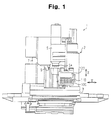
- Fig. 1 is a diagrammatic front view of a machining center in accordance with an embodiment;
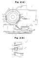
- Fig. 2(A) is a diagrammatic side view of the machining center;
- Fig. 2(B) is a partial explanation view of an enlarged vicinity of a tool picking portion;
- Fig. 3 is an enlarged partial side view of a tool exchange device;
- Fig. 4 is an enlarged partial side view of the tool exchange device;
- Fig. 5 is a block diagram showing electric circuit of an NC device of the machining center;
- Fig. 6 is a flowchart performed by a main control unit;
- Fig. 7 is an explanation view of a display screen of a display unit;
- Fig. 8 is an explanation view of a display screen of the display unit;
- Fig. 9 is an explanation view of a display screen of the display unit; and
- Fig. 10 is a flowchart performed by the main control unit.
- With reference to Figs. 1 to 10, an embodiment of an NC machine tool of the present invention embodied by a vertical machining center will be described below.
- As shown in Fig. 1, 2(A), and 2(B), a
machining center 1 has amain unit 2. A table 3 is supported by themain unit 2 so as to be movable in a horizontal direction (X-axis direction, Y-axis direction). Acolumn 2a of themain unit 2 is provided with aspindle head 5. Thespindle head 5 is disposed above the table 3. Thespindle head 5 is supported so as to be movable in a vertical direction (Z-axis direction) with respect to the table 3. - The table 3 and the
spindle head 5 are held in themachining center 1 so as to be relatively movable along three axes (X, Y, Z), all perpendicular to one another. In themachining center 1, the amount of movement of the table 3 and thespindle head 5 is controlled by anNC device 100 and a work set on the table 3 is machined by use of a tool K attached to thespindle head 5. - The tool K can be attached/detached to/from a
spindle 5a of thespindle head 5. Atool exchanger 6 is formed on a side of thespindle head 5. As shown in Fig. 2(A), a disc-like tool magazine 7 is rotatably supported by themain unit 2. On a periphery of thetool magazine 7 are arranged a plurality ofpockets 7a foraccommodating tools 9. Thetools 9 can be attached/detached to/from thepockets 7a. A cylindrical cover 2b which covers a circumference of thetool magazine 7 is formed on themain unit 2. A tool picking port 2c is formed on the cover 2b. The tool picking port 2c corresponds to a tool picking position A. - As shown in Fig. 2(B), as the
tool magazine 7 is rotated, eachtool pocket 7a is disposed at the tool picking position A. The operator can manually exchange the tool in thetool pocket 7a disposed at the tool picking position A. Asensor 40 as a detector for detecting the presence or absence of thetool 9 in eachtool pocket 7a is provided at the tool picking position A in thetool magazine 7. Thesensor 40 is connected to amain control unit 130 of the NC device 100 (refer to Fig. 5) and a signal output from thesensor 40 is read by themain control unit 130. When the output signal from thesensor 40 is changed from OFF to ON, themain control unit 130 determines that the tool has been manually exchanged. A unique pocket number "TNo." is given to eachtool pocket 7a in thetool magazine 7. - The
spare tools 9 are located in thetool magazine 7. Thetool exchanger 6 has a rotational arm 6a which protrudes downward and aholder 6b is rotatably supported by a lower end of the rotational arm 6a. As the rotational arm 6a rotates, the tool K attached to thespindle 5a is replaced by thetool 9 held by theholder 6b. As thetool magazine 7 rotates, thetools 9 in thetool pockets 7a, such as an end mill and a drill, are consecutively disposed at the tool picking position A. - Next, with reference to Fig. 5, the
NC device 100 in themachining center 1 will be described. - As shown in Fig. 5, the
NC device 100 has aninput unit 110 including a keyboard, adisplay unit 120 including a display device such as liquid crystal display and an alarm device, themain control unit 130 as a controller,various memories 150 to 170, amachining control unit 200 and a toolexchange control unit 300. Themain control unit 130 is connected to theinput unit 110, thedisplay unit 120, thevarious memories 150 to 170, themachining control unit 200 and the toolexchange control unit 300 via abus 140. - A
machining program memory 150 stores a machining program for machining a work. Adata memory 160 as a data storage means stores data on the tool used in the machining center 1 (hereinafter referred to as tool data) therein. The tool data includes TNo., tool name, diameter, suffix, tool diameter, tool length, cutting edge correction, life time, operating time, group No., diameter correction amount and length correction amount. - The "suffix" represents a code for identifying between tools having the same diameter. The "cutting edge correction" represents correction amount of an end position of the tool on the basis of consumption amount through machining. The "life time" represents life time of the tool. The "operating time" represents operating time of the tool. The "group No." represents a number of a tool group (in a group of tools having the same shape and size, when the one tool has been used for a period exceeding the life time, the group number is given to the spare tool). The "ID No." represents an ID number of the tool. The "diameter correction amount" represents correction amount of tool diameter. The "length correction amount" represents correction amount of tool length.
- When a tool is set in the
tool pocket 7a, the tool data is input from theinput unit 110 by means of a keyboard and stored in a predetermined area of thedata memory 160. At this time, the tool data is associated with thetool pocket 7a and stored in thedata memory 160. The "diameter correction amount", the "length correction amount", the "tool diameter", the "tool length" and the "cutting edge correction" are tool data used for executing the machining program as data to be checked. - A
system program memory 170 stores various programs for controlling themain control unit 130, themachining control unit 200 and the toolexchange control unit 300. Themachining control unit 200 is connected to aspindle control unit 210, a toolholder control unit 220 and atable control unit 230 via thebus 140. Thespindle control unit 210 is connected to a spindlehead moving unit 215. The spindlehead moving unit 215 controls movement of thespindle head 5 in the Z direction. Thespindle control unit 210 controls driving of a motor (not shown) for rotating thespindle 5a of thespindle head 5. Thetable control unit 230 controls movement of the table 3 in the X direction and the Y direction. The toolexchange control unit 300 is connected to thetool magazine 7 and thetool exchanger 6. Themain control unit 130 is connected to a drivingcircuit 46 via thebus 140. Themain control unit 130 controls lighting of analarm lamp 45 as an alarm device through the drivingcircuit 46. - The
input unit 110 is provided with anunclamp switch 42 as a detector and acycle start button 43 as a selector. When theunclamp switch 42 is turned on, according to a control command from themachining control unit 200, the toolholder control unit 220 opens a tool holder not shown in thespindle head 5. Thus, the tool can be manually removed from the tool holder. When theunclamp switch 42 is turned off, according to a control command from themachining control unit 200, the toolholder control unit 220 closes the tool holder in thespindle head 5. Thus, the tool is held by the tool holder. Based on an output signal from theunclamp switch 42, themain control unit 130 associates tool data of the tool attached to the tool holder with a tool exchange flag and sets the flag in thedata memory 160. - When the output signal from the
sensor 40 is switched from OFF to ON, themain control unit 130 associates tool data of the tool in thetool pocket 7a having "TNo." with a tool exchange flag and sets the flag in thedata memory 160. In this embodiment, thedata memory 160 serves as a first storage device in which exchange history is stored when the tool is manually exchanged and as a third storage device in which update history is stored when the tool data is updated. - Next, operations of the above-mentioned
machining center 1 will be described. - Fig. 6 is a flowchart performed by the
main control unit 130 when the tool data is changed. When a display command for tool data is input from theinput unit 110, themain control unit 130 allows a tool data screen to be displayed on the display unit 120 (refer to Fig. 1) (S10). Fig. 7 shows ascreen 120a of thedisplay unit 120 on which the tool data is displayed. Data corresponding to items of "TNo.", "tool name" and "diameter" is displayed on adisplay area 120b for showing a tool list. Data such as "tool name", "diameter", "suffix" of the tool selected by use of a pointer not shown or the like is displayed on adisplay area 120c. Thedisplay area 120c is provided with display andinput sections 120d corresponding to the respective items. The data stored in thedata memory 160 is displayed in the display andinput sections 120d. New data can be input to the display andinput sections 120d. - When new data is input from the input unit 110 (YES at S20), the
main control unit 130 determines whether the input data is data to be checked (S30). When data for determining whether the data is data to be checked is not input, themain control unit 130 keeps the tool data screen to be displayed on the display unit 120 (S10). - When the input data is not data to be checked (NO at S30), the
main control unit 130 temporarily finishes this flow. When the input data is data to be checked (YES at S30), themain control unit 130 as a calculator calculates, as a variation, a difference between the data input as a correction value (hereinafter referred to as an input value) and the value stored in thedata memory 160 prior to input of the input value (hereinafter referred to as a set value) at S40. - The
main control unit 130 as a comparator determines whether the input value is proper by comparing an absolute value of the variation with a threshold value (S50) . In this case, the threshold value is previously set according to the type of the data to be checked. When the absolute value of the variation is the threshold value or smaller, themain control unit 130 determines that the input value is proper and finishes this processing temporarily (NO at S50). When the absolute value of the variation exceeds the threshold value, themain control unit 130 pops up theconfirmation display area 120e on thescreen 120a to make the operator confirm the input value (refer to Fig. 8). - Fig. 8 shows an example in which the
confirmation display 120e concerning the "tool length" is displayed on thedisplay unit 120. The "current set value", "input value" and "variation" concerning the tool length are displayed as theconfirmation display 120e and "OK" is displayed as a confirmation button. The input value is displayed in thedisplay section 120f of the "input value" and new data can be input. As shown in Fig. 9, themain control unit 130 allows amessage 120g "Please confirm input data" to be displayed on thescreen 120a of thedisplay unit 120. Since a data input error can occur when the absolute value of the variation exceeds the threshold value, themain control unit 130 causes display ofsuch message 120g, thereby prompting the operator to confirm the input value. - Next, when the "OK" button is clicked by means of a mouse (YES at S70), the
main control unit 130 determines that the input value has been confirmed and sets an input value confirmed flag (S80). When new data is input to thedisplay section 120f (NO at S70), themain control unit 130 executes a series of processing at S40 and subsequent steps with respect to the input data. - After the setting of the input value confirmed flag, the
main control unit 130 stores the input value in the data memory 160 (S90). In other words, themain control unit 130 rewrites the tool data stored in thedata memory 160 to the newly input data. At the time of updating data, the input value confirmed flag is associated with the updated tool data and the associated flag is stored in thedata memory 160. Themain control unit 130 sets an update data flag on the tool, the data to be checked of which is updated, (S100) and terminates this processing. - Next, with reference to Fig. 5 and Fig. 10, change check routine performed in automatic operation will be described.
- The
main control unit 130 reads the machining program from themachining program memory 150. When machining of the work is started, themain control unit 130 reads data on the tool K attached to thespindle head 5 from thedata memory 160. For the tool K attached to the spindle head 5 (refer to Fig. 3), themain control unit 130 as a determining device determines the update data flag and the tool exchange flag are set or reset from the data memory 160 (S200, S220, S280). On the basis of the machining program and the tool data, themain control unit 130 determines whichtool pocket 7a has accommodated the tool K attached to thespindle head 5. - When both of the update data flag and the tool exchange flag are reset (YES at S200), the
main control unit 130 performs automatic operation (S210). When the outcome of S200 is NO, themain control unit 130 determines whether the update data flag is set and the tool exchange flag is reset (S220). - When the outcome of S220 is YES, the
main control unit 130 determines whether the input value confirmed flag is set to the tool data read in performing this routine (S230). When the input value confirmed flag is set (YES at S230), themain control unit 130 determines that the operator has confirmed that the absolute value of the variation between the set value and the input value exceeds the threshold value, and the operation proceeds to S240. On the other hand, when the input value confirmed flag is not set to tool data (NO at S230), since the variation of the input value is the threshold value or smaller as apparent from the flowchart of Fig. 6, themain control unit 130 determines that interference of the tool with the machine will not be generated. That is, themain control unit 130 as an invalidating device invalidates determination of "YES" at S220, and the operation proceeds to S210. - At S240, the
main control unit 130 displays that "only input value of tool data is changed" on thedisplay unit 120 and performs feed hold to pause feeding of the tool K by thespindle head 5. To prompt the operator to confirm the input value of the tool data, themain control unit 130 turns on thealarm lamp 45. Here, the feed hold and the processing of turning on thealarm lamp 45 will be described as a common action below. - When the outcome of S220 is NO, the
main control unit 130 determines whether the update data flag is reset and the tool exchange flag is set (S280). When the outcome of S280 is YES, to prompt the operator to confirm the input value of the tool K and the tool data, themain control unit 130 displays "tool change, tool data non-input, confirmation needed" on thedisplay unit 120 and performs the above-mentioned common action (S290). - When the outcome of S280 is NO, the
main control unit 130 determines that the update data flag and the tool exchange flag are set, and the operation proceeds to S300. To prompt the operator to confirm the input value of the tool K and the tool data, themain control unit 130 displays "new tool, confirm input value of tool data" on thedisplay unit 120 and performs the above-mentioned common action (S300). Themain control unit 130 prompts the operator to confirm the tool K and the input value of the tool data, and then the operation proceeds to S250. - At 3250, the
main control unit 130 determines whether thecycle start button 43 of theinput unit 110 is turned on by the operator. When thecycle start button 43 is turned on (YES at S250), themain control unit 130 moves to S260. Themain control unit 130 decreases rapid traverse override of the tool K up to a predetermined value (%) and terminates this routine (S260). The rapid traverse override at this time is set to be a slower speed than the ordinary rapid traverse override. When next cutting feeding is commanded while executing a machining program, themain control unit 130 returns the changed rapid traverse override to an ordinary value. When thecycle start button 43 is not turned on (NO at S250), thecontrol unit 130 executes the other processing on the basis of the operation by the other input unit 110 (S270) and terminates this routine. - As described above, this embodiment obtains the following advantages.
- In this embodiment, when the tool K is manually exchanged, movement of the tool is stopped by performing feed hold during automatic machining. Thus, it is possible to prompt the operator to confirm tool exchange, thereby preventing tool exchange error from occurring. When the tool data is updated, a caution concerning the tool is displayed on the
display unit 120. Accordingly, it is possible to prompt the operator to confirm tool data update, thereby preventing a tool data update error from occurring. - In this embodiment, when the
sensor 40 detects presence or absence of a tool in thepocket 7a and when theunclamp switch 42 detects that a tool has been removed from thespindle head 5, the tool exchange flag is stored in thedata memory 160. Thus, it is possible to prompt the operator to confirm tool exchange on the basis of the data stored in thedata memory 160. Furthermore, display of tool exchange and tool data update on thedisplay unit 120 enables the operator to confirm them. - In this embodiment, when the tool exchange flag is set and the update data flag is not set, the fact that the tool data is not updated is displayed on the
display unit 120. Thus, it is possible to prompt the operator to confirm that the exchanging tool is properly accommodated in the tool pocket or there is no omission of input of the tool data and to take an appropriate step. By only displaying whether the input value of the tool data is correct or not, it is possible to draw the operator's attention, thereby preventing an input error by the operator. Furthermore, by displaying the tool data and the input value as well as the difference between them on thedisplay unit 120, it is possible to prompt the operator to confirm the input value. - In this embodiment, when the absolute value of the variation is larger than the threshold value, by displaying the variation on the
display unit 120, it is possible to prompt the operator to confirm the input value. Furthermore, since feeding of the tool K is set to be slower than an ordinary value when performing rapid traverse override, shock due to interference of the tool K with the machine can be minimized. - In this embodiment, when the variation of the input value is the threshold value or smaller, the
main control unit 130 invalidates determination on the update data flag and the tool exchange flag. For example, in order to improve machining accuracy after cutting of the work, the tool data may be rewritten by the operator at the next cutting. In this case, themain control unit 130 determines that the difference between the tool data and the correction value is smaller than the threshold value and is proper, and invalidates determination on the update data flag and the tool exchange flag. In this manner, cutting of the next work can be performed without stopping movement of the tool. - This embodiment may be modified as follows.
- In this embodiment, although all of the input value, the current set value and the variation are displayed on the
display unit 120 as shown in Fig. 8, only the input value, or the input value and the variation may be displayed. - Although the present invention is embodied in the vertical machining center, the present invention may be embodied in the other NC machine tool such as a horizontal machining center and a composite processing machine.
- Attention is directed to all papers and documents which are filed concurrently with or previous to this specification in connection with this application and which are open to public inspection with this specification, and the contents of all such papers and documents are incorporated herein by reference.
- All of the features disclosed in this specification (including any accompanying claims, abstract and drawings), and/or all of the steps of any method or process so disclosed, may be combined in any combination, except combinations where at least some of such features and/or steps are mutually exclusive.
- Each feature disclosed in this specification (including any accompanying claims, abstract and drawings) may be replaced by alternative features serving the same, equivalent or similar purpose, unless expressly stated otherwise. Thus, unless expressly stated otherwise, each feature disclosed is one example only of a generic series of equivalent or similar features.
- The invention is not restricted to the details of the foregoing embodiment(s). The invention extends to any novel one, or any novel combination, of the features disclosed in this specification (including any accompanying claims, abstract and drawings), or to any novel one, or any novel combination, of the steps of any method or process so disclosed.
Claims (9)
- An NC machine tool that moves a head, to which a tool is attached, and a work relative to each other, thereby machining the work with the tool, the NC machine tool being characterized by:exchange history storage means for storing, when the tool has been manually exchanged, history of the exchange;data storage means for storing data on the tool;update history storage means for storing, when the data is updated, history of the update;determination means for determining whether there has been a change related to the tool on the basis of the exchange history and the update history;control means for stopping movement of the tool on the basis of a determination result of the determination means; andalarm means for issuing an alarm about the tool on the basis of the determination result of the determination means.
- The NC machine tool according to claim 1 characterized by detection means for detecting that the tool has been manually exchanged,
wherein the exchange history is stored in the exchange history storage means on the basis of an output signal from the detection means. - The NC machine tool according to claim 1 or 2, characterized in that the alarm means is display means,
wherein, when movement of the tool is stopped, the control means allows a message on the tool to be displayed on the display means on the basis of the exchange history and the update history. - The NC machine tool according to claim 3, characterized in that, when there is the exchange history and there is not the update history on the tool attached to the head, the control means allows the fact that the data has not been updated to be displayed on the display means.
- The NC machine tool according to claim 3 or 4, characterized by an input unit for inputting correction value of the data,
wherein, when the correction value is input from the input unit, the control means allows both of the data stored in the second storage means and input correction value to be displayed on the display means. - The NC machine tool according to claim 5, characterized by calculation means for calculating a difference between the data and the correction value,
wherein the calculation means allows the difference between the data and the correction value to be displayed on the display means. - The NC machine tool according to claim 6, characterized by comparing means for comparing the difference between the data and the correction value with a threshold value,
wherein the comparing means determines whether the difference is proper and allows the difference to be displayed on the display means on the basis of the determination result. - The NC machine tool according to anyone of claims 5 to 7, characterized in that the input unit outputs a confirmation signal according to an external operation,
wherein the control means updates the data to the correction value on the basis of the confirmation signal from the input unit. - The NC machine tool according to claim 7, characterized by invalidating means for invalidating the determination result of the determination means when the difference is proper.
Applications Claiming Priority (1)
| Application Number | Priority Date | Filing Date | Title |
|---|---|---|---|
| JP2005246281A JP4580846B2 (en) | 2005-08-26 | 2005-08-26 | NC machine tool |
Publications (3)
| Publication Number | Publication Date |
|---|---|
| EP1758004A2 true EP1758004A2 (en) | 2007-02-28 |
| EP1758004A3 EP1758004A3 (en) | 2009-09-02 |
| EP1758004B1 EP1758004B1 (en) | 2014-04-09 |
Family
ID=37398868
Family Applications (1)
| Application Number | Title | Priority Date | Filing Date |
|---|---|---|---|
| EP06119539.2A Not-in-force EP1758004B1 (en) | 2005-08-26 | 2006-08-25 | NC Machine Tool |
Country Status (4)
| Country | Link |
|---|---|
| US (1) | US7313458B2 (en) |
| EP (1) | EP1758004B1 (en) |
| JP (1) | JP4580846B2 (en) |
| CN (1) | CN100464266C (en) |
Families Citing this family (36)
| Publication number | Priority date | Publication date | Assignee | Title |
|---|---|---|---|---|
| JP4366291B2 (en) * | 2004-10-29 | 2009-11-18 | ヤマザキマザック株式会社 | NC device |
| JP4580846B2 (en) * | 2005-08-26 | 2010-11-17 | ヤマザキマザック株式会社 | NC machine tool |
| JP3119701U (en) * | 2005-11-25 | 2006-03-09 | キタムラ機械株式会社 | Machine Tools |
| JP4955451B2 (en) * | 2007-05-16 | 2012-06-20 | ヤマザキマザック株式会社 | Control method of compound lathe device, compound lathe device, blade position registration device, and blade position detection device |
| JP5295645B2 (en) * | 2008-06-04 | 2013-09-18 | 株式会社ディスコ | Cutting equipment |
| JP5344156B2 (en) * | 2009-03-30 | 2013-11-20 | ブラザー工業株式会社 | Numerically controlled machine tool and its tool change method |
| US8954201B2 (en) | 2011-06-03 | 2015-02-10 | Energyhub, Inc. | Realization of energy savings potential through feedback |
| US8588957B2 (en) * | 2011-10-24 | 2013-11-19 | Sikorsky Aircraft Corporation | Cutting tool data verification system and method |
| KR101856198B1 (en) * | 2011-12-26 | 2018-05-11 | 두산공작기계 주식회사 | Apparatus and method for controlling tool changer in numerical control |
| JP5888106B2 (en) * | 2012-05-17 | 2016-03-16 | 三星ダイヤモンド工業株式会社 | Scribe processing system |
| JP2013237133A (en) * | 2012-05-17 | 2013-11-28 | Mitsuboshi Diamond Industrial Co Ltd | Scribing system |
| JP5994380B2 (en) * | 2012-05-17 | 2016-09-21 | 三星ダイヤモンド工業株式会社 | Scribe processing system |
| JP5994381B2 (en) * | 2012-05-17 | 2016-09-21 | 三星ダイヤモンド工業株式会社 | Scribe processing system |
| JP5966600B2 (en) * | 2012-05-17 | 2016-08-10 | 三星ダイヤモンド工業株式会社 | Scribe processing system |
| JP5966601B2 (en) * | 2012-05-17 | 2016-08-10 | 三星ダイヤモンド工業株式会社 | Scribe processing system |
| JP2013237135A (en) * | 2012-05-17 | 2013-11-28 | Mitsuboshi Diamond Industrial Co Ltd | Scribing system |
| JP5966599B2 (en) * | 2012-05-17 | 2016-08-10 | 三星ダイヤモンド工業株式会社 | Scribe processing system |
| JP5888107B2 (en) * | 2012-05-17 | 2016-03-16 | 三星ダイヤモンド工業株式会社 | Scribe processing system |
| CN104619461B (en) * | 2012-10-01 | 2016-05-04 | 山崎马扎克公司 | machine tool |
| JPWO2014068667A1 (en) * | 2012-10-30 | 2016-09-08 | 株式会社牧野フライス製作所 | Machining program creation method and apparatus |
| CN103885389A (en) * | 2012-12-20 | 2014-06-25 | 北汽福田汽车股份有限公司 | Numerical control process program processing method |
| US10078324B2 (en) * | 2013-08-30 | 2018-09-18 | Makino Milling Machine Co., Ltd. | Tool management system |
| JP6279431B2 (en) * | 2014-08-26 | 2018-02-14 | Dmg森精機株式会社 | Machine Tools |
| JP6117841B2 (en) * | 2015-03-26 | 2017-04-19 | ファナック株式会社 | Numerical control device with function to prevent erroneous input of tool offset data |
| US9827640B2 (en) * | 2015-06-18 | 2017-11-28 | Jorge Uriarte | Apparatus and a system for automatic tool change by threading engagement for a CNC milling machine |
| JP6805600B2 (en) * | 2016-07-21 | 2020-12-23 | 株式会社リコー | Diagnostic equipment, diagnostic systems, diagnostic methods and programs |
| DE112017003357B4 (en) * | 2017-01-27 | 2024-08-01 | Mitsubishi Electric Corp. | Selection device, selection procedure and program |
| JP2020055043A (en) * | 2018-09-28 | 2020-04-09 | 豊和工業株式会社 | Machine Tools |
| JP6882248B2 (en) * | 2018-11-14 | 2021-06-02 | ファナック株式会社 | Tool mounting abnormality detector |
| CN109724427A (en) * | 2018-12-21 | 2019-05-07 | 成都易华天宇试验设备有限责任公司 | A control system suitable for curing oven |
| JP7425094B2 (en) * | 2020-02-07 | 2024-01-30 | ファナック株式会社 | diagnostic equipment |
| JP7230874B2 (en) * | 2020-03-31 | 2023-03-01 | ブラザー工業株式会社 | Numerical controller |
| JP7352736B2 (en) * | 2020-06-05 | 2023-09-28 | Dmg森精機株式会社 | Magazines and machine tools |
| CN115755766A (en) * | 2022-11-16 | 2023-03-07 | 新代科技(苏州)有限公司 | Group cutter function for machining center |
| CN116621444A (en) * | 2023-04-24 | 2023-08-22 | 彩虹(合肥)液晶玻璃有限公司 | Cutter replacing system and method for machine tool cutting |
| WO2025163853A1 (en) * | 2024-02-01 | 2025-08-07 | ファナック株式会社 | Numerical control device and method for controlling machine tool |
Citations (3)
| Publication number | Priority date | Publication date | Assignee | Title |
|---|---|---|---|---|
| JPH07223148A (en) | 1994-02-07 | 1995-08-22 | Sanyo Electric Co Ltd | Tool check device for nc machine tool |
| JPH1133867A (en) | 1997-07-14 | 1999-02-09 | Komatsu Koki Kk | Tool interference protecting method and protecting device |
| US20010001841A1 (en) | 1992-12-02 | 2001-05-24 | Kazuhisa Sugiyama | Numerically controlled machining apparatus for automatically exchanging tools and workpieces |
Family Cites Families (31)
| Publication number | Priority date | Publication date | Assignee | Title |
|---|---|---|---|---|
| DE2740873A1 (en) | 1977-09-10 | 1979-03-29 | Kunzmann Werkzeugmaschinenfabr | NC machine tool prodn. process - uses programme cassette generating audio or visual commands for instructional purpose |
| JPS5642806A (en) * | 1979-09-18 | 1981-04-21 | Fanuc Ltd | Sequence control system for numerical control machine tool |
| JPS57156145A (en) | 1981-03-16 | 1982-09-27 | Kitamura Kikai Kk | Control panel equipped with voice output apparatus for nc machine tool |
| JPS58143945A (en) * | 1982-02-13 | 1983-08-26 | Makino Milling Mach Co Ltd | Mold processing system |
| US4908746A (en) | 1986-10-15 | 1990-03-13 | United States Data Corporation | Industrial control system |
| JP2993158B2 (en) * | 1990-04-05 | 1999-12-20 | 三菱電機株式会社 | Numerical control unit |
| JP2900646B2 (en) | 1991-07-10 | 1999-06-02 | 三菱電機株式会社 | Numerical control unit |
| JP2658633B2 (en) | 1991-07-10 | 1997-09-30 | 三菱電機株式会社 | Communication device |
| JP2531868Y2 (en) * | 1992-01-24 | 1997-04-09 | オークマ株式会社 | Numerical controller with automatic adjustment tool identification function |
| JPH05233050A (en) * | 1992-02-18 | 1993-09-10 | Fanuc Ltd | Parameter input system for cnc |
| JPH05324039A (en) | 1992-05-26 | 1993-12-07 | Fanuc Ltd | Numerical controller |
| JP2809039B2 (en) * | 1993-03-25 | 1998-10-08 | 三菱電機株式会社 | Laser processing machine and laser processing method |
| JP3593353B2 (en) * | 1993-11-02 | 2004-11-24 | 株式会社アマダ | Sheet cutting data generator in automatic programming system for sheet metal working |
| JPH0822314A (en) * | 1994-07-05 | 1996-01-23 | Mori Seiki Co Ltd | Numerical control device with warning display function |
| JPH08132332A (en) * | 1994-11-04 | 1996-05-28 | Fanuc Ltd | Position shift correction method in machine tool |
| EP2275921B1 (en) | 1995-07-31 | 2012-06-06 | Canon Kabushiki Kaisha | Image processing apparatus |
| JP3687980B2 (en) * | 1996-11-07 | 2005-08-24 | 株式会社ミツトヨ | Measurement program creation in NC machining and machining management that executed this measurement program |
| JP3200023B2 (en) | 1997-01-16 | 2001-08-20 | ファナック株式会社 | Control equipment for production equipment |
| JPH1142534A (en) * | 1997-07-30 | 1999-02-16 | Toyoda Mach Works Ltd | Tool control device and control device for machine tool provided with tool control function |
| US6292712B1 (en) * | 1998-01-29 | 2001-09-18 | Northrop Grumman Corporation | Computer interface system for a robotic system |
| EP1146407A4 (en) * | 1999-07-05 | 2005-05-25 | Mitutoyo Corp | METHOD FOR WRITING DIGITAL CONTROL PROGRAM AND DIGITAL-CONTROLLED MACHINING SYSTEM |
| US6609038B1 (en) | 2000-09-11 | 2003-08-19 | Milacron Inc. | Multi-media enhanced program controlled machine |
| JP4140805B2 (en) * | 2000-12-28 | 2008-08-27 | 株式会社スギノマシン | Machining center with manual tool change function |
| US20020193972A1 (en) | 2001-06-14 | 2002-12-19 | Ntn Corporation | Workshop facility design and operation support system enabling verification of the entire workshop to be performed easily |
| JP2003058215A (en) * | 2001-08-09 | 2003-02-28 | Mori Seiki Co Ltd | Similar machining data search device and automatic programming device |
| JP2003103435A (en) * | 2001-09-28 | 2003-04-08 | Brother Ind Ltd | Machine tool, tool judgment method and tool judgment program |
| JP2004066417A (en) * | 2002-08-08 | 2004-03-04 | Mori Seiki Co Ltd | Tool management method and tool management device |
| CN1577338A (en) * | 2003-07-28 | 2005-02-09 | 鸿富锦精密工业(深圳)有限公司 | Metal plate pressed computer auxiliary producing system and method |
| CN1581176A (en) * | 2003-08-04 | 2005-02-16 | 鸿富锦精密工业(深圳)有限公司 | Computer value control-code analoging system and method |
| JP4366291B2 (en) | 2004-10-29 | 2009-11-18 | ヤマザキマザック株式会社 | NC device |
| JP4580846B2 (en) * | 2005-08-26 | 2010-11-17 | ヤマザキマザック株式会社 | NC machine tool |
-
2005
- 2005-08-26 JP JP2005246281A patent/JP4580846B2/en not_active Expired - Lifetime
-
2006
- 2006-08-25 US US11/467,484 patent/US7313458B2/en not_active Expired - Fee Related
- 2006-08-25 EP EP06119539.2A patent/EP1758004B1/en not_active Not-in-force
- 2006-08-25 CN CNB2006101265486A patent/CN100464266C/en not_active Expired - Fee Related
Patent Citations (3)
| Publication number | Priority date | Publication date | Assignee | Title |
|---|---|---|---|---|
| US20010001841A1 (en) | 1992-12-02 | 2001-05-24 | Kazuhisa Sugiyama | Numerically controlled machining apparatus for automatically exchanging tools and workpieces |
| JPH07223148A (en) | 1994-02-07 | 1995-08-22 | Sanyo Electric Co Ltd | Tool check device for nc machine tool |
| JPH1133867A (en) | 1997-07-14 | 1999-02-09 | Komatsu Koki Kk | Tool interference protecting method and protecting device |
Also Published As
| Publication number | Publication date |
|---|---|
| CN100464266C (en) | 2009-02-25 |
| CN1920716A (en) | 2007-02-28 |
| US7313458B2 (en) | 2007-12-25 |
| EP1758004B1 (en) | 2014-04-09 |
| US20070050079A1 (en) | 2007-03-01 |
| EP1758004A3 (en) | 2009-09-02 |
| JP2007058773A (en) | 2007-03-08 |
| JP4580846B2 (en) | 2010-11-17 |
Similar Documents
| Publication | Publication Date | Title |
|---|---|---|
| EP1758004B1 (en) | NC Machine Tool | |
| US11556901B2 (en) | Preventive maintenance system of machine tool | |
| US6640676B2 (en) | Tool presetter and tool offset amount calculation method | |
| US20080021591A1 (en) | Numerical controller having interference check function | |
| US7899574B2 (en) | Machine-tool controller | |
| KR860002004B1 (en) | The processing method for numerical control | |
| US9400497B2 (en) | Numerical control device | |
| US10416649B2 (en) | Numerical controller that prevents a tool compensation value setting error | |
| US8688257B2 (en) | Programming apparatus | |
| EP2915626B1 (en) | Processing program generation method and device | |
| JP2523191B2 (en) | Sequence control device | |
| EP2104013B1 (en) | Numerical controller with machining restart function | |
| US20080086221A1 (en) | Machine-tool controller | |
| JP4947534B2 (en) | Machine tool and method of operating machine tool | |
| EP3705954B1 (en) | Machine tool having function of automatically correcting machining program in tool replacement | |
| US20250334952A1 (en) | Numerical control device and computer-readable storage medium | |
| US20190202017A1 (en) | Selecting device, selecting method, and program | |
| JPH1142534A (en) | Tool control device and control device for machine tool provided with tool control function | |
| WO2022190155A1 (en) | Workpiece processing apparatus | |
| JP2008234278A (en) | Numerical control device, control program, control program recording medium, and machine tool | |
| WO2023042249A1 (en) | Machine tool, control method, and control program | |
| KR100254185B1 (en) | Tool checking method | |
| JP4396554B2 (en) | Numerical control apparatus, numerical control method, and control program | |
| JP2009258997A (en) | Working machine | |
| JPH04104304A (en) | Work method for numerically controlled machine tool |
Legal Events
| Date | Code | Title | Description |
|---|---|---|---|
| PUAI | Public reference made under article 153(3) epc to a published international application that has entered the european phase |
Free format text: ORIGINAL CODE: 0009012 |
|
| AK | Designated contracting states |
Kind code of ref document: A2 Designated state(s): AT BE BG CH CY CZ DE DK EE ES FI FR GB GR HU IE IS IT LI LT LU LV MC NL PL PT RO SE SI SK TR |
|
| AX | Request for extension of the european patent |
Extension state: AL BA HR MK YU |
|
| RIN1 | Information on inventor provided before grant (corrected) |
Inventor name: KIKATA, KAZUHIROYAMAZAKI MAZAK CORPORATION Inventor name: SUMIDA, YASUHARUYAMAZAKI MAZAK CORPORATION Inventor name: ITOH, HIROSHIYAMAZAKI MAZAK CORPORTION |
|
| PUAL | Search report despatched |
Free format text: ORIGINAL CODE: 0009013 |
|
| AK | Designated contracting states |
Kind code of ref document: A3 Designated state(s): AT BE BG CH CY CZ DE DK EE ES FI FR GB GR HU IE IS IT LI LT LU LV MC NL PL PT RO SE SI SK TR |
|
| AX | Request for extension of the european patent |
Extension state: AL BA HR MK RS |
|
| RIC1 | Information provided on ipc code assigned before grant |
Ipc: G05B 19/4093 20060101AFI20090730BHEP |
|
| 17P | Request for examination filed |
Effective date: 20100106 |
|
| AKX | Designation fees paid |
Designated state(s): DE FR GB IT |
|
| 17Q | First examination report despatched |
Effective date: 20130220 |
|
| GRAP | Despatch of communication of intention to grant a patent |
Free format text: ORIGINAL CODE: EPIDOSNIGR1 |
|
| INTG | Intention to grant announced |
Effective date: 20140108 |
|
| GRAS | Grant fee paid |
Free format text: ORIGINAL CODE: EPIDOSNIGR3 |
|
| GRAA | (expected) grant |
Free format text: ORIGINAL CODE: 0009210 |
|
| AK | Designated contracting states |
Kind code of ref document: B1 Designated state(s): DE FR GB IT |
|
| REG | Reference to a national code |
Ref country code: GB Ref legal event code: FG4D |
|
| REG | Reference to a national code |
Ref country code: DE Ref legal event code: R096 Ref document number: 602006040982 Country of ref document: DE Effective date: 20140522 |
|
| PGFP | Annual fee paid to national office [announced via postgrant information from national office to epo] |
Ref country code: DE Payment date: 20140821 Year of fee payment: 9 |
|
| PGFP | Annual fee paid to national office [announced via postgrant information from national office to epo] |
Ref country code: FR Payment date: 20140821 Year of fee payment: 9 Ref country code: GB Payment date: 20140821 Year of fee payment: 9 |
|
| PGFP | Annual fee paid to national office [announced via postgrant information from national office to epo] |
Ref country code: IT Payment date: 20140825 Year of fee payment: 9 |
|
| REG | Reference to a national code |
Ref country code: DE Ref legal event code: R097 Ref document number: 602006040982 Country of ref document: DE |
|
| PLBE | No opposition filed within time limit |
Free format text: ORIGINAL CODE: 0009261 |
|
| STAA | Information on the status of an ep patent application or granted ep patent |
Free format text: STATUS: NO OPPOSITION FILED WITHIN TIME LIMIT |
|
| 26N | No opposition filed |
Effective date: 20150112 |
|
| REG | Reference to a national code |
Ref country code: DE Ref legal event code: R097 Ref document number: 602006040982 Country of ref document: DE Effective date: 20150112 |
|
| REG | Reference to a national code |
Ref country code: DE Ref legal event code: R119 Ref document number: 602006040982 Country of ref document: DE |
|
| GBPC | Gb: european patent ceased through non-payment of renewal fee |
Effective date: 20150825 |
|
| PG25 | Lapsed in a contracting state [announced via postgrant information from national office to epo] |
Ref country code: IT Free format text: LAPSE BECAUSE OF NON-PAYMENT OF DUE FEES Effective date: 20150825 |
|
| REG | Reference to a national code |
Ref country code: FR Ref legal event code: ST Effective date: 20160429 |
|
| PG25 | Lapsed in a contracting state [announced via postgrant information from national office to epo] |
Ref country code: GB Free format text: LAPSE BECAUSE OF NON-PAYMENT OF DUE FEES Effective date: 20150825 Ref country code: DE Free format text: LAPSE BECAUSE OF NON-PAYMENT OF DUE FEES Effective date: 20160301 |
|
| PG25 | Lapsed in a contracting state [announced via postgrant information from national office to epo] |
Ref country code: FR Free format text: LAPSE BECAUSE OF NON-PAYMENT OF DUE FEES Effective date: 20150831 |