EP1757845A1 - Übertragungselement mit zur Übertragung von Betätigungsbewegungen - Google Patents
Übertragungselement mit zur Übertragung von Betätigungsbewegungen Download PDFInfo
- Publication number
- EP1757845A1 EP1757845A1 EP06015797A EP06015797A EP1757845A1 EP 1757845 A1 EP1757845 A1 EP 1757845A1 EP 06015797 A EP06015797 A EP 06015797A EP 06015797 A EP06015797 A EP 06015797A EP 1757845 A1 EP1757845 A1 EP 1757845A1
- Authority
- EP
- European Patent Office
- Prior art keywords
- sheet metal
- transmission element
- metal segment
- segment
- reinforcement
- Prior art date
- Legal status (The legal status is an assumption and is not a legal conclusion. Google has not performed a legal analysis and makes no representation as to the accuracy of the status listed.)
- Granted
Links
- 230000005540 biological transmission Effects 0.000 title claims description 92
- 229910000831 Steel Inorganic materials 0.000 claims abstract description 6
- 239000010959 steel Substances 0.000 claims abstract description 6
- 239000002184 metal Substances 0.000 claims description 87
- 230000002787 reinforcement Effects 0.000 claims description 37
- 239000000463 material Substances 0.000 claims description 7
- 238000005520 cutting process Methods 0.000 claims description 2
- 230000003014 reinforcing effect Effects 0.000 abstract description 6
- 230000000903 blocking effect Effects 0.000 description 4
- 238000010276 construction Methods 0.000 description 2
- 238000004519 manufacturing process Methods 0.000 description 2
- 239000007787 solid Substances 0.000 description 2
- 230000008719 thickening Effects 0.000 description 2
- 238000003466 welding Methods 0.000 description 2
- 238000005452 bending Methods 0.000 description 1
- 230000007797 corrosion Effects 0.000 description 1
- 238000005260 corrosion Methods 0.000 description 1
- 230000001419 dependent effect Effects 0.000 description 1
- 238000004080 punching Methods 0.000 description 1
- 239000011343 solid material Substances 0.000 description 1
Images
Classifications
-
- F—MECHANICAL ENGINEERING; LIGHTING; HEATING; WEAPONS; BLASTING
- F16—ENGINEERING ELEMENTS AND UNITS; GENERAL MEASURES FOR PRODUCING AND MAINTAINING EFFECTIVE FUNCTIONING OF MACHINES OR INSTALLATIONS; THERMAL INSULATION IN GENERAL
- F16H—GEARING
- F16H63/00—Control outputs from the control unit to change-speed- or reversing-gearings for conveying rotary motion or to other devices than the final output mechanism
- F16H63/02—Final output mechanisms therefor; Actuating means for the final output mechanisms
- F16H63/08—Multiple final output mechanisms being moved by a single common final actuating mechanism
- F16H63/20—Multiple final output mechanisms being moved by a single common final actuating mechanism with preselection and subsequent movement of each final output mechanism by movement of the final actuating mechanism in two different ways, e.g. guided by a shift gate
-
- F—MECHANICAL ENGINEERING; LIGHTING; HEATING; WEAPONS; BLASTING
- F16—ENGINEERING ELEMENTS AND UNITS; GENERAL MEASURES FOR PRODUCING AND MAINTAINING EFFECTIVE FUNCTIONING OF MACHINES OR INSTALLATIONS; THERMAL INSULATION IN GENERAL
- F16H—GEARING
- F16H63/00—Control outputs from the control unit to change-speed- or reversing-gearings for conveying rotary motion or to other devices than the final output mechanism
- F16H63/02—Final output mechanisms therefor; Actuating means for the final output mechanisms
- F16H63/30—Constructional features of the final output mechanisms
-
- F—MECHANICAL ENGINEERING; LIGHTING; HEATING; WEAPONS; BLASTING
- F16—ENGINEERING ELEMENTS AND UNITS; GENERAL MEASURES FOR PRODUCING AND MAINTAINING EFFECTIVE FUNCTIONING OF MACHINES OR INSTALLATIONS; THERMAL INSULATION IN GENERAL
- F16H—GEARING
- F16H63/00—Control outputs from the control unit to change-speed- or reversing-gearings for conveying rotary motion or to other devices than the final output mechanism
- F16H63/02—Final output mechanisms therefor; Actuating means for the final output mechanisms
- F16H63/08—Multiple final output mechanisms being moved by a single common final actuating mechanism
- F16H63/20—Multiple final output mechanisms being moved by a single common final actuating mechanism with preselection and subsequent movement of each final output mechanism by movement of the final actuating mechanism in two different ways, e.g. guided by a shift gate
- F16H2063/208—Multiple final output mechanisms being moved by a single common final actuating mechanism with preselection and subsequent movement of each final output mechanism by movement of the final actuating mechanism in two different ways, e.g. guided by a shift gate using two or more selecting fingers
-
- F—MECHANICAL ENGINEERING; LIGHTING; HEATING; WEAPONS; BLASTING
- F16—ENGINEERING ELEMENTS AND UNITS; GENERAL MEASURES FOR PRODUCING AND MAINTAINING EFFECTIVE FUNCTIONING OF MACHINES OR INSTALLATIONS; THERMAL INSULATION IN GENERAL
- F16H—GEARING
- F16H63/00—Control outputs from the control unit to change-speed- or reversing-gearings for conveying rotary motion or to other devices than the final output mechanism
- F16H63/02—Final output mechanisms therefor; Actuating means for the final output mechanisms
- F16H63/30—Constructional features of the final output mechanisms
- F16H2063/3083—Shift finger arrangements, e.g. shape or attachment of shift fingers
Definitions
- the invention relates to a transmission element which is associated with a shaft, with the actuating movements are transferable and which is formed from at least one sheet metal segment, wherein the sheet metal segment receives at least one finger-like actuator, and wherein the sheet metal segment at least partially an arcuate in the circumferential direction about the pivot axis of the transmission element curved shaped sheet metal is ,.
- Such a transmission element is in DE 44 32 382 A1 described.
- the transmission elements are in manual transmissions of vehicles with shift rails or shift shafts in connection.
- the transmission elements transmit switching and or selecting movements and the associated forces of the waves on other switching elements such as shift sleeves and forks and are also alternately to block certain selection or switching movements intended.
- the transmission element in this case has a hub for seating on the corresponding shift shaft or shift rod.
- the seat is slidable or fixed and optionally secured in the direction of rotation or pivoting about a pivot axis of the transmission element against rotation.
- the transmission element of the type has a segment of a sleeve made of sheet metal and is generally formed in the form of a half shell. Such segments and also other parts of the transmission element are simple and inexpensive to produce as stamped and or cold formed as by punching, bending, stamping and drawing and to connect by welding or riveting together. Since the transmission elements are composed of individual parts, complicated structures such as latching contours can be realized.
- the transmission elements generally have segments with which as many functions as possible, such as the optional transmission and blocking of dialing and switching movements can be made.
- the segments then also have two or more of the finger-like actuating elements and also continuous recesses, for example for the engagement of blocking elements.
- the individual transmission components are arranged very close together. Therefore, the dimensions and wall thickness of the items are limited.
- the transmission elements such as switching and locking sleeves are adapted to these requirements, due to the arbitrarily composable structure with respect to the space optimally designed space-saving.
- the material consumption for the production is relatively low. It is therefore desirable for reasons of economy and in order to claim space as little as possible, sheets with low output levels Making use of the transmission elements.
- the thinness of the individual elements are therefore limited, since partly high switching forces are transmitted by means of the transmission elements.
- the dimensions of the segments are therefore adapted to the loads relatively large, so that they do not deform unduly in actuation movements such as switching, dialing and blocking movements.
- the built around the appropriately dimensioned transmission elements transmission is, contrary to optimal design, correspondingly large and heavy dimensions.
- the object of the invention is therefore to provide a transmission element with which the aforementioned disadvantages are avoided.
- the sheet metal segment has at least one radial reinforcement.
- the radial dimensions of the sheet metal segment on the reinforcement are at least greater than radial dimensions of at least any other immediately adjacent to reinforcing circumferentially adjacent portions of the sheet metal segment or any other arbitrary directly adjacent to the reinforcement sections of the sheet segment or the sections between the reinforcement and a hub.
- the sheet metal segment has a thickening at the point where the finger-like actuating element projects away from the metal sheet. Thickening strengthens the base of the actuator on the segment. Canceling or tearing off the shift finger from the segment is prevented.
- the reinforcement is placed, for example, on the piece of sheet metal radially below the finger-like actuating element and welded to the sheet metal segment or, as an embodiment of the invention provides integrally formed with the sheet.
- the actuating element is preferably a forming part, for example of the steel material 16MnCr5 but also of any other steels, is placed on the reinforcement with the thicker sheet metal and with the reinforcement, e.g. with laser or resistance welding, welded or alternatively riveted.
- the actuating element is directed radially inwardly away from the pivoting axis radially inwardly away from the sheet metal segment.
- the entire structural unit of the transmission element is preferably hardened after assembly at least on the entire surface or at least on the surface of the shift finger and optionally coated against corrosion.
- the actuating element is integrally formed from the material of the segment with the reinforcement of the thicker sheet metal and bent like a lever from the segment radially outward or inward.
- the material is preferably steel material, preferably designated 16MnCr5.
- the reinforced portion of the segment on which sits the finger-like actuator is due to space and functionally lever-like from the rest of the sheet metal segment from or out of the sheet segment and preferably extends axially, i. in one of the directions in which the pivot axis is directed.
- the segment is recessed at least on both sides of the reinforcement in the circumferential direction, at least so that the reinforcement adjoins a recess at least on the circumferential side and the segment continues in both axial directions with a weaker metal sheet.
- the sheet metal segment is of any shape, may have ramp contours and / or, as an embodiment of the invention provides, so half-shell-shaped, that the sheet metal segment at least in sections in any transverse to the pivot axis cutting planes by radii is described.
- Each of the radii describes an arc of an imaginary circle segment and radiates perpendicular to the pivot axis of the pivot axis.
- the arc spans an outgoing from the pivot axis circle segment.
- the radian measure is at most ⁇ and thus the arc angle is at most 180 °.
- the hub is a flow press, stamped part or a drawn part, but can also be machined.
- the hub bridges the distance between the shaft seat and the part of the sheet metal segment either with solid material or by a corresponding sheet metal construction of pipe sections, collar and radial disc.
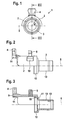
- FIGS 1 to 3 show a transmission element 1 in different views.
- the transmission element 1 is formed from at least one sheet metal segment 2, a hub 3 and actuators 4 and 5.
- the hub 3 is a drawn part made of sheet metal with a sleeve 10, with a disc 11 and with a collar 12 and is flared at the collar 12.
- the sleeve 10 is a pivot shaft 6 concentric shaft seat 13 of the transmission element. 1
- the sheet metal segment 2 is arranged radially to the shaft seat 13 spaced with an inner portion 15 on the hub 3, so that the hub 3 is a connection between the sheet segment 2 and a shaft, not shown. From the sleeve 10 is radially in one piece, the disc 11 to the outside. The collar 12 is angled as a seat for the sheet metal segment 2 of the disc 11. A portion 16 of the sheet metal segment 2 is axially rectified with the pivot axis 6 freely from the hub 3 and limits the inside to the pivot axis 6 towards a "filled with air" circular cylinder segment in the, if the transmission element is installed, for example, a part of a housing of a transmission can be arranged at a distance from the segment.
- the sheet segment 2 receives the two finger-like actuators 4 and 5.
- the sheet segment 2, the hub 3 and the actuators 4 and 5 are chip-break parts made of steel.
- the sheet metal segment 2 is partially a sheet-shaped in the circumferential direction about the pivot axis 6 of the transmission element 1 in the form of a half-shell curved sheet metal.
- the sheet metal segment 1 is formed so that the sheet metal segment 1 at least in the transverse to the pivot axis 6 image plane spans in the arc 7 of an imaginary and bounded by the arc 7 and a line of symmetry 8 circular segment.
- the radian of the arc 7 is in this case ⁇ and thus the arc angle 180 °.
- the radius R of the circle segment starts from the pivot axis 6.
- the sheet metal segment 2 has, where the actuating element 4 protrudes from the sheet segment 1, a radial reinforcement 9.
- the radial dimensions A of the sheet metal segment 2 on the reinforcement 9 are larger than radial dimensions of at least all other arbitrary sections which are directly adjacent to the reinforcement 9 on the circumference and on the hub side.
- the sheet metal segment 2 is therefore thicker at the reinforcement 9 than at any other arbitrary portion of the sheet metal segment 2.
- the reinforcement 9 is integrally formed with the sheet, and introduced, for example, in the semifinished sheet before or during the production of the sheet metal segment 2.
- the sheet segment 2 is recessed on both sides of the gain in the circumferential direction so that at least a portion 14 of the sheet metal segment 2 with the reinforcement 9 is axially aligned with the pivot axis 6 freely furthest out of the sheet segment 2.
- the part 14 of the sheet segment 2 with the reinforcement 9 protrudes like a lever out of the sheet segment 2 in one of the directions from the sheet segment 2, in which the pivot axis 6 is directed.
- the actuator 4 is radially directed away from the pivot axis 6 directed to the reinforcement 9 with the thicker sheet and welded, for example, to this.
- the actuator 5 is inserted into the sheet segment 2 and optionally welded or riveted to the sheet segment 2.
- the actuating element 5 is followed, at least in a circumferential direction, by a recess 19 for the engagement of a further switching or blocking element (not illustrated).
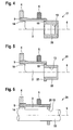
- FIG. 4 shows a transmission element 17 whose essential structure corresponds to the sheet metal segment 2 and the actuating elements 4 and 5 of the transmission element 1.
- the sheet segment 2 is seated on a hub 20.
- the radial gap between the shaft seat 13 and the inner portion 15 is filled with the material of the hub 20 designed as a forged or sintered part.
- Figure 5 shows a transmission element 21, the essential structure with the sheet metal segment 2 and with the actuators 4 and 5 corresponds to that of the transmission element 1.
- the sheet segment 2 is seated on a hub 22.
- the radial gap between the shaft seat 13 and the inner portion 15 is filled by the part solid designed as extruded part hub 22 and the radial collar 23 of the hub 22.
- FIG. 6 shows a transmission element 24 whose essential construction with the sheet metal segment 2 and the actuating elements 4 and 5 corresponds to that of the transmission element 1.
- the sheet segment 2 is seated on a hub-shaped disk 25.
- the radial gap between the shaft seat 13 on the shaft 33 and the inner portion 15 is filled by the disk 25.
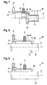
- Figure 7 shows a transmission element 26, with a sheet metal segment 27, on which the actuating element 28 is integrally formed with the reinforcement 9 of the thicker sheet metal.
- the actuating element 28 is angled out of the sheet metal of the transmission element 26.
- the transmission element 26 is seated in the already described on the hub 3 and the hub 3 is provided for a press or sliding fit on a shaft, not shown.
- FIG. 8 shows a transmission element 29 without a hub.
- the transmission element 29 is the sheet metal segment 30 and has the actuating elements 4 and 5.
- the sheet metal segment 30 is substantially executed as the sheet metal segment 2 of the transfer segment 1, but has deviating to a radial arm 31 with a through hole 32.
- the shaft seat 13 is formed for a shaft 33.
- FIG. 9 shows a transmission element 34.
- the transmission element 34 is the sheet metal segment 35 and has the actuating elements 4 and 5.
- the sheet metal segment 35 is substantially carried out as the sheet metal segment 2 of the transmission segment 1, but deviating to a radial arm 36, with which the transmission element 34 is fixed on the shaft 33 designed as a pivotable and displaceable switching shaft.
Landscapes
- Engineering & Computer Science (AREA)
- General Engineering & Computer Science (AREA)
- Mechanical Engineering (AREA)
- Chairs For Special Purposes, Such As Reclining Chairs (AREA)
- Mechanical Operated Clutches (AREA)
Abstract
Description
- Die Erfindung betrifft ein Übertragungselement, das einer Welle zugeordnet ist, mit dem Betätigungsbewegungen übertragbar sind und das aus zumindest einem Blechsegment gebildet ist, wobei das Blechsegment wenigstens ein fingerartiges Betätigungselement aufnimmt, und wobei das Blechsegment zumindest abschnittsweise ein bogenförmig in Umfangsrichtung um die Schwenkachse des Übertragungselementes gekrümmt geformtes Blech ist,.
- Ein derartiges Übertragungselement ist in
DE 44 32 382 A1 beschrieben. Die Übertragungselemente stehen in Schaltgetrieben von Fahrzeugen mit Schaltstangen oder Schaltwellen in Verbindung. Die Übertragungselemente übertragen Schalt- und oder Wählbewegungen und die damit verbundenen Kräfte von den Wellen auf weitere Schaltelemente wie Schaltmuffen und Gabeln und sind wechselweise auch zum Sperren bestimmter Wähl- oder Schaltbewegungen vorgesehen. Das Übertragungselement weist in diesem Fall eine Nabe für den Sitz auf der entsprechenden Schaltwelle oder Schaltstange auf. Der Sitz ist verschiebbar oder fest und wahlweise in Drehrichtung oder Schwenkrichtung um eine Schwenkachse des Übertragungselements gegen Verdrehen gesichert. - Das Übertragungselement der Gattung weist ein Segment einer Hülse aus Blech auf und ist in der Regel halbschalenförmig ausgebildet. Derartige Segmente und auch weitere Teile des Übertragungselements sind einfach und kostengünstig als Stanz- und oder Kaltumformteile wie durch Stanzen, Biegen, Prägen und Ziehen herzustellen und durch Schweißen oder Nieten miteinander zu verbinden. Da die Übertragungselemente aus Einzelteilen zusammengesetzt sind, lassen sich auch komplizierte Strukturen wie zum Beispiel Rastkonturen realisieren.
- Auf dem Segment sitzt mindestens ein Betätigungselement in Form eines Schaltfingers und/oder in Form weiterer fingerartig abstehende Betätigungselemente, wie Sperrfinger oder Finger zum Betätigen von Schaltern oder ähnlichem. Die Übertragungselemente weisen in der Regel Segmente auf, mit denen möglichst viele Funktionen, wie wahlweise das Übertragen und alternativ das Sperren von Wähl- und Schaltbewegungen vorgenommen werden können. Die Segmente weisen dann auch zwei oder mehr der fingerartigen Betätigungselemente und auch durchgehende Aussparungen z.B für den Eingriff von Sperrelementen auf.
- In modernen kompakten Fahrzeuggetrieben sind die einzelnen Getriebebauteile sehr eng ineinander angeordnet. Deshalb sind den Abmessungen und der Wandstärke der Einzelteile Grenzen gesetzt. Die Übertragungselemente, wie Schalt- und Sperrhülsen sind, diesen Anforderungen angepasst, aufgrund der beliebig zusammensetzbaren Struktur hinsichtlich des Bauraumes optimal Platz sparend auslegbar. Der Materialverbrauch zur Herstellung ist relativ gering. Es wird deshalb aus Gründen der Sparsamkeit und um so wenig wie möglich Bauraum zu beanspruchen angestrebt, Bleche mit geringen Ausgangstärken zur Herstellung der Übertragungselemente einzusetzen.
- Der Dünnwandigkeit der einzelnen Elemente sind deshalb jedoch Grenzen gesetzt, da mittels der Übertragungselemente teils hohe Schaltkräfte übertragen werden. Die Abmessungen der Segmente sind deshalb an die Belastungen angepasst relativ groß, so dass sich diese bei Betätigungsbewegungen wie Schalt-, Wähl- und Sperrbewegungen nicht unzulässig verformen. Das um die entsprechend dimensionierten Übertragungselemente gebaute Getriebe ist, abweichend von optimaler Ausführung, entsprechend groß und schwer dimensioniert.
- Die Aufgabe der Erfindung ist es daher, ein Übertragungselement zu schaffen, mit dem die zuvor genannten Nachteile vermieden werden.
- Diese Aufgabe ist nach dem Gegenstand des Anspruches 1 und weiterer abhängiger Ansprüche gelöst. Das Blechsegment weist zumindest da wo das Betätigungselement von dem Blechsegment absteht, wenigstens eine radiale Verstärkung auf. Die radialen Abmessungen des Blechsegments an der Verstärkung sind mindesten größer als radiale Abmessungen mindestens aller weiteren beliebigen unmittelbar zur Verstärkung umfangsseitig benachbarter Abschnitte des Blechsegments oder aber aller weiteren beliebigen unmittelbar zur Verstärkung benachbarten Abschnitte des Blechsegmentes oder die Abschnitte zwischen der Verstärkung und einer Nabe.
- Das Blechsegment weist demnach an der Stelle, wo das fingerartig abstehende Betätigungselement von dem Blech abgeht, eine Verdickung auf. Mit der Verdickung wird die Basis des Betätigungselementes am Segment verstärkt. Das Abbrechen oder Abreißen des Schaltfingers vom Segment wird verhindert.
- Die Verstärkung ist zum Beispiel auf das Blechstück radial unterhalb des fingerartigen Betätigungselementes aufgesetzt und mit dem Blechsegment verschweißt oder, wie eine Ausgestaltung der Erfindung vorsieht, einstückig mit dem Blech ausgebildet.
- Das Betätigungselement ist vorzugsweise ein Umformteil , beispielsweise aus dem Stahlwerkstoff 16MnCr5 aber auch aus beliebigen anderen Stählen, ist auf die Verstärkung mit dem dickeren Blech aufgesetzt und mit der Verstärkung, z.B. mit Laser- oder mit Widerstandsschweißen, verschweißt oder ist alternativ vernietet. Das Betätigungselement ist wahlweise von dem Blechsegment aus nach innen vorzugsweise radial von der Schwenkachse weg radial nach außen gerichtet.
- Die gesamte Baueinheit des Übertragungselements ist vorzugsweise nach dem Zusammenbau zumindest an der gesamten Oberfläche oder zumindest an der Oberfläche der Schaltfinger gehärtet und ggf. gegen Korrosion beschichtet.
- Alternativ dazu ist das Betätigungselement einstückig aus dem Material des Segments mit der Verstärkung aus dem dickeren Blech ausgebildet und hebelartig von dem Segment radial nach außen oder innen abgewinkelt. Das Material ist vorzugsweise Stahlwerkstoff, bevorzugt mit der Bezeichnung 16MnCr5.
- Der verstärkte Abschnitt des Segmentes, auf dem das fingerartige Betätigungselement sitzt, steht aus Platzgründen und funktionsbedingt hebelartig von dem Rest des Blechsegments ab oder aus dem Blechsegment hervor und verläuft dabei vorzugsweise axial, d.h. in eine der Richtungen in die die Schwenkachse gerichtet ist. Alternativ ist das Segment zumindest beidseitig der Verstärkung in Umfangsrichtung zumindest so ausgespart, dass sich der Verstärkung zumindest umfangsseitig eine Ausnehmung anschließt und sich das Segment in beide axialen Richtungen mit schwächerem Blech fortsetzt.
- Das Blechsegment ist von beliebiger Form, kann Rampenkonturen aufweisen und/oder ist, wie eine Ausgestaltung der Erfindung vorsieht, so halbschalenförmig ausgebildet, dass das Blechsegment zumindest abschnittsweise in beliebigen quer zur Schwenkachse verlaufenden Schnittebenen durch Radien beschrieben ist. Jeder der Radien beschreibt einen Bogen eines gedachten Kreissegmentes und geht senkrecht zur Schwenkachse strahlenförmig von der Schwenkachse aus. Der Bogen überspannt ein von der Schwenkachse ausgehendes Kreissegment. Das Bogenmaß ist höchstens π und somit ist der Bogenwinkel höchstens 180°.
- Wenn das Übertragungselement eine Nabe aufweist, ist die Nabe ein Fließpressteil, Stanzteil oder ein Ziehteil, kann aber auch spanabhebend hergestellt sein. Die Nabe überbrückt den Abstand zwischen dem Wellensitz und dem Teil des Blechsegments entweder mit Vollmaterial oder durch eine entsprechende Blechkonstruktion aus Rohrabschnitten, Kragen und radialer Scheibe.
- Die Erfindung wird nachfolgend anhand von Ausführungsbeispielen näher erläutert. Es zeigen:
- Figur 1
- eine Frontalansicht eines Übertragungselementes mit einer gezogenen Nabe,
- Figur 2
- die Seitenansicht des Übertragungselements nach Figur 1,
- Figur 3
- einen Längsschnitt durch das Übertragungselement nach Figur 1, entlang der Linie III - III,
- Figur 4
- ein alternatives Übertragungselement mit einer massiv ausgebildeten Nabe im Längsschnitt entlang der Schwenkachse des Übertragungselements
- Figur 5
- ein Übertragungselement mit einer teilmassiv ausgebildeten Nabe im Längsschnitt entlang der Schwenkachse des Übertragungselements,
- Figur 6
- ein Übertragungselement mit einer scheibenförmig ausgebildeten Nabe im Längsschnitt entlang der Schwenkachse des Übertragungselements,
- Figur 7
- ein Übertragungselement, bei dem das fingerartige Betätigungselement einteilig mit der Verstärkung ausgebildet ist, im Längsschnitt entlang der Schwenkachse des Übertragungselements,
- Figur 8
- ein Übertragungselement ohne Nabe, bei dem das Blechsegment mit einem Wellensitz versehen ist, im Längsschnitt entlang der Schwenkachse des Übertragungselements und
- Figur 9
- ein Übertragungselement ohne Nabe, bei dem das Blechsegment auf der Welle sitzt, ohne die Welle zu umfassen, im Längsschnitt entlang der Schwenkachse des Übertragungselements.
- Die Figuren 1 bis 3 zeigen ein Übertragungselement 1 in verschiedenen Ansichten. Das Übertragungselement 1 ist aus zumindest einem Blechsegment 2, aus einer Nabe 3 und aus Betätigungselementen 4 und 5 gebildet. Die Nabe 3 ist ein Ziehteil aus Blech mit einer Hülse 10, mit einer Scheibe 11 und mit einem Kragen 12 und ist am Kragen 12 aufgeweitet. Die Hülse 10 ist ein zur Schwenkachse 6 konzentrischer Wellensitz 13 des Übertragungselements 1.
- Das Blechsegment 2 ist radial zu dem Wellensitz 13 beabstandet mit einem Innenabschnitt 15 auf der Nabe 3 angeordnet, so dass die Nabe 3 eine Verbindung zwischen dem Blechsegment 2 und einer nicht dargestellten Welle ist. Von der Hülse 10 geht radial einstückig die Scheibe 11 nach außen ab. Der Kragen 12 ist als Sitz für das Blechsegment 2 von der Scheibe 11 abgewinkelt. Ein Teilabschnitt 16 des Blechsegments 2 steht axial gleichgerichtet mit der Schwenkachse 6 frei von der Nabe 3 ab und begrenzt dabei innenseitig zur Schwenkachse 6 hin ein "mit Luft ausgefülltes" Kreiszylindersegment in dem, wenn das Übertragungselement verbaut ist, zum Beispiel eine Teil eines Gehäuses eines Getriebes mit Abstand zum Segment angeordnet sein kann.
- Das Blechsegment 2 nimmt die zwei fingerartig ausgebildeten Betätigungselemente 4 und 5 auf. Das Blechsegment 2, die Nabe 3 und die Betätigungselemente 4 und 5 sind Spanlosteile aus Stahl.
- Das Blechsegment 2 ist abschnittsweise ein bogenförmig in Umfangsrichtung um die Schwenkachse 6 des Übertragungselementes 1 halbschalenförmig gekrümmt geformtes Blech. Wie aus Figur 1 hervorgeht ist das Blechsegment 1 so halbschalenförmig ausgebildet, dass das Blechsegment 1 zumindest in der quer zur Schwenkachse 6 verlaufenden Bildebene den im Bogen 7 eines gedachten und von dem Bogen 7 und einer Symmetrielinie 8 begrenzten Kreissegmentes überspannt. Das Bogenmaß des Bogens 7 ist in diesem Fall π und somit der Bogenwinkel 180°. Der Radius R des Kreissegments geht von der Schwenkachse 6 aus.
- Das Blechsegment 2 weist da, wo das Betätigungselement 4 von dem Blechsegment 1 absteht, eine radiale Verstärkung 9 auf. Die radialen Abmessungen A des Blechsegments 2 an der Verstärkung 9 sind größer als radiale Abmessungen mindestens aller weiteren beliebigen unmittelbar zur Verstärkung 9 umfangsseitig und nabenseitig benachbarten beliebigen Abschnitte. Das Blechsegment 2 ist also an der Verstärkung 9 dicker als an jedem weiteren beliebigen Abschnitt des Blechsegments 2. Die Verstärkung 9 ist einstückig mit dem Blech ausgebildet, und beispielsweise in das Halbzeug Blech vor der oder während der Herstellung des Blechssegments 2 eingebracht.
- Das Blechsegment 2 ist beidseitig der Verstärkung in Umfangsrichtung so ausgespart, dass zumindest ein Teil 14 des Blechsegments 2 mit der Verstärkung 9 axial gleichgerichtet mit der Schwenkachse 6 frei am weitesten aus dem Blechsegment 2 hervor steht. Das Teil 14 des Blechsegmentes 2 mit der Verstärkung 9 ragt hebelartig aus dem Blechsegment 2 in eine der Richtungen aus dem Blechsegment 2 hervor, in die die Schwenkachse 6 gerichtet ist. Das Betätigungselement 4 ist radial von der Schwenkachse 6 weggerichtet auf die Verstärkung 9 mit dem dickeren Blech aufgesetzt und zum Beispiel an dieser verschweißt. Das Betätigungselement 5 ist in das Blechsegment 2 eingesteckt und wahlweise mit dem Blechsegment 2 verschweißt oder vernietet. Dem Betätigungselement 5 schließt sich zumindest in eine Umfangsrichtung eine Aussparung 19 für den Eingriff eines weiteren nicht dargestellten Schalt- bzw. Sperrelements an.
- Figur 4 zeigt ein Übertragungselement 17, dessen wesentlicher Aufbau mit dem Blechsegment 2 und den Betätigungselementen 4 und 5 dem des Übertragungselementes 1 entspricht. Das Blechsegment 2 sitzt auf einer Nabe 20. Der radiale Spalt zwischen dem Wellensitz 13 und dem Innenabschnitt 15 ist mit dem Werkstoff der massiv als Schmiede- oder Sinterteil ausgeführten Nabe 20 ausgefüllt.
- Figur 5 zeigt ein Übertragungselement 21, dessen wesentlicher Aufbau mit dem Blechsegment 2 und mit den Betätigungselementen 4 und 5 dem des Übertragungselementes 1 entspricht. Das Blechsegment 2 sitzt auf einer Nabe 22. Der radiale Spalt zwischen dem Wellensitz 13 und dem Innenabschnitt 15 ist durch die teil massiv als Fließpressteil ausgeführte Nabe 22 und den radialen Kragen 23 der Nabe 22 ausgefüllt.
- Figur 6 zeigt ein Übertragungselement 24, dessen wesentlicher Aufbau mit dem Blechsegment 2 und den Betätigungselementen 4 und 5 dem des Übertragungselementes 1 entspricht. Das Blechsegment 2 sitzt auf einer nabenförmig ausgeführten Scheibe 25. Der radiale Spalt zwischen dem Wellensitz 13 auf der Welle 33 und dem Innenabschnitt 15 ist durch die Scheibe 25 ausgefüllt.
- Figur 7 zeigt ein Übertragungselement 26, mit einem Blechsegment 27, an dem das Betätigungselement 28 einstückig mit der Verstärkung 9 aus dem dickeren Blech ausgebildet ist. Das Betätigungselement 28 ist aus dem Blech des Übertragungselements 26 abgewinkelt. Das Übertragungselement 26 sitzt in der schon beschriebenen Weise auf der Nabe 3 und die Nabe 3 ist für einen Press- oder Schiebesitz auf einer nicht dargestellten Welle vorgesehen.
- Figur 8 zeigt ein Übertragungselement 29 ohne Nabe. Das Übertragungselement 29 ist das Blechsegment 30 und weist die Betätigungselemente 4 und 5 auf. Das Blechsegment 30 ist im wesentlichen ausgeführt wie das Blechsegment 2 des Übertragungssegments 1, weist jedoch abweichend dazu einen Radialarm 31 mit einem Durchgangsloch 32 auf. In dem Durchgangsloch 32 ist der Wellensitz 13 für eine Welle 33 ausgebildet.
- In Figur 9 ist ein Übertragungselement 34 abgebildet. Das Übertragungselement 34 ist das Blechsegment 35 und weist die Betätigungselemente 4 und 5 auf. Das Blechsegment 35 ist im wesentlichen ausgeführt wie das Blechsegment 2 des Übertragungssegments 1, weist jedoch abweichend dazu einen Radialarm 36 auf, mit dem das Übertragungselement 34 auf der als schwenkbare und verschiebbare Schaltwelle ausgebildeten Welle 33 fest ist.
-
- 1
- Übertragungselement
- 2
- Blechsegment
- 3
- Nabe
- 4
- Betätigungselement
- 5
- Betätigungselement
- 6
- Schwenkachse
- 7
- Bogen
- 8
- Symmetrielinie
- 9
- Verstärkung
- 10
- Hülse
- 11
- Scheibe
- 12
- Kragen
- 13
- Wellensitz
- 14
- Teil mit Verstärkung
- 15
- Innenabschnitt
- 16
- Teilabschnitt
- 17
- Übertragungselement
- 18
- Nabe
- 19
- Aussparung
- 20
- Nabe
- 21
- Übertragungselement
- 22
- Nabe
- 23
- Kragen
- 24
- Übertragungselement
- 25
- Scheibe
- 26
- Übertragungselement
- 27
- Blechsegment
- 28
- Betätigungselement
- 29
- Übertragungselement
- 30
- Blechsegment
- 31
- Radialarm
- 32
- Durchgangsloch
- 33
- Welle
- 34
- Übertragungselement
- 35
- Blechsegment
- 36
- Radialarm
Claims (21)
- Übertragungselement (1, 17, 21, 24, 26, 29, 34), das einer Welle (33) zugeordnet ist, mit dem Betätigungsbewegungen übertragbar sind und das aus zumindest einem Blechsegment (2, 27, 30, 35) gebildet ist, wobei das Blechsegment (2, 27, 30, 35) wenigstens ein fingerartiges Betätigungselement (4, 5, 28) aufnimmt, und wobei das Blechsegment (2, 27, 30, 35) zumindest abschnittsweise ein bogenförmig in Umfangsrichtung um die Schwenkachse (6) des Übertragungselementes (1, 17, 21, 24, 26, 29, 34) gekrümmt geformtes Blech ist, dadurch gekennzeichnet, dass das Blechsegment (2, 27, 30, 35), zumindest da wo zumindest eines der Betätigungselemente (4, 28) von dem Blechsegment (2, 27, 30, 35) absteht wenigstens eine radiale Verstärkung (9) aufweist, wobei die radialen Abmessungen des Blechsegments (2, 27, 30, 35) an der der Verstärkung (9) größer sind als alle weiteren in radiale Richtung betrachteten Abmessungen aller weiteren beliebigen unmittelbar zur Verstärkung (9) umfangsseitig benachbarten Abschnitte des Blechsegments (2, 27, 30, 35). (Fig. 1 - 9)
- Übertragungselement nach Anspruch 1, dadurch gekennzeichnet, dass das Übertragungselement (1, 17, 21, 24, 26) eine Nabe (3, 20, 22) mit dem Wellensitz (13) aufweist, wobei das Blechsegment (2, 27), radial zu der Welle (33) beabstandet, auf der Nabe (3, 20, 22) angeordnet ist, so dass die Nabe (3, 20, 22) eine Verbindung zwischen dem Blechsegment (2, 27) und der Welle (33) ist. (Fig. 1 - 7)
- Übertragungselement nach Anspruch 1, dadurch gekennzeichnet, dass die radialen Abmessungen des Blechsegmentes (2, 27, 30, 35) an der Verstärkung (9) größer sind als radiale Abmessungen mindestens aller weiteren beliebigen unmittelbar zur Verstärkung (9) benachbarten Abschnitte des Blechsegmentes (2, 27, 30, 35) zwischen der Verstärkung (9) und der Nabe (3, 20, 22). (Fig. 1 - 9)
- Übertragungselement nach Anspruch 1, dadurch gekennzeichnet, dass die Verstärkung (9) einstückig mit dem Blech ausgebildet ist. (Fig. 1 - 9)
- Übertragungselement nach Anspruch 1, dadurch gekennzeichnet, dass das Blech an der Verstärkung (9) dicker ist als an jedem weiteren beliebigen Abschnitt des Blechsegmentes (2, 27, 30, 35). (Fig. 1 - 9)
- Übertragungselement nach Anspruch 1, dadurch gekennzeichnet, dass das Betätigungselement (4) auf der Verstärkung (9) mit dem dickeren Blech aufgesetzt ist. (Fig. 1 - 6, 8, 9)
- Übertragungselement nach Anspruch 6, dadurch gekennzeichnet, dass das Betätigungselement (4) am dickeren Blech mit der Verstärkung (9) verschweißt ist.
- Übertragungselement nach Anspruch 1, dadurch gekennzeichnet, dass das Betätigungselement (28) einstückig mit der Verstärkung aus dem dickeren Blech ausgebildet ist. (Figur 7)
- Übertragungselement nach Anspruch 8, dadurch gekennzeichnet, dass das Betätigungselement (28) aus dem Blech des Übertragungselements (26) abgewinkelt ist.
- Übertragungselement nach Anspruch 9, dadurch gekennzeichnet, dass das Betätigungselement (4, 5, 28) radial von der Schwenkachse (6) weggerichtet ist. (Fig. 1- 9)
- Übertragungselement nach Anspruch 1, dadurch gekennzeichnet, das zumindest ein Teil des Blechsegmentes (2, 27, 30, 35) mit der Verstärkung (9) hebelartig aus dem Blechsegment (2, 27, 30, 35) hervorragt. (Fig. 1 - 9)
- Übertragungselement nach Anspruch 11, dadurch gekennzeichnet, dass der Teil des Blechsegmentes (2, 27, 30, 35) mit der Verstärkung (9) in eine der Richtungen aus dem Blechsegment (2, 27, 30, 35) hervorsteht, in die die Schwenkachse (6) gerichtet ist. (Fig. 1 - 9)
- Übertragungselement nach Anspruch 1, dadurch gekennzeichnet, dass das Blechsegment (2, 27, 30, 35) beidseitig der Verstärkung (9) in Umfangsrichtung zumindest so ausgespart ist, dass sich der Verstärkung (9) zumindest umfangsseitig eine Ausnehmung anschließt. (Fig. 1 - 9)
- Übertragungselement nach Anspruch 13, dadurch gekennzeichnet, dass das Blechsegment (2, 27, 30, 35) so ausgespart ist, dass zumindest ein Teil des Blechsegments (2, 27, 30, 35) mit der Verstärkung (9) axial gleichgerichtet mit der Schwenkachse (6) frei aus dem Blechsegment (2, 27, 30, 35) hervorsteht. (Fig. 1 - 9)
- Übertragungselement nach Anspruch 14, dadurch gekennzeichnet, dass sich das Betätigungselement (4, 5, 28) radial dem Teil des Blechsegments (2, 27, 30, 35) anschließt, das am weitesten aus dem Blechsegment hervorsteht. (Fig. 1 - 9)
- Übertragungselement nach Anspruch 1, dadurch gekennzeichnet, dass das Blechsegment (2, 27, 30, 35) so halbschalenförmig ausgebildet ist, dass das Blechsegment (2, 27, 30, 35) zumindest abschnittsweise in beliebigen quer zur Schwenkachse (6) verlaufenden Schnittebenen im Bogen (7) ein gedachtes Kreissegment überspannt, wobei das Bogenmaß des Bogens (7) höchstens π ist und wobei der Radius des Kreissegments von der Schwenkachse (6) ausgeht. (Fig. 1)
- Übertragungselement nach Anspruch 1, dadurch gekennzeichnet, dass die Nabe (3, 20, 22), das Blechsegment (2, 27, 30, 35) und das Betätigungselement (4, 5, 28) Spanlosteile aus Stahl sind. (Fig. 1 - 9)
- Übertragungselement nach Anspruch 1, dadurch gekennzeichnet, dass das Blechsegment (2) radial zur Welle (33) beabstandet ist und mit einem Innenabschnitt (15) auf der Nabe (20, 22) sitzt und dass radiale Abstände zwischen der Welle (33) und dem Innenabschnitt (15) mit dem Werkstoff der Nabe (20, 22) ausgefüllt sind. (Fig. 4, 5)
- Übertragungselement nach Anspruch 18, dadurch gekennzeichnet, dass ein Teilabschnitt des Blechsegments (2) axial gleichgerichtet mit der Schwenkachse (6) frei von der Nabe (20, 22) absteht. (Fig. 4, 5)
- Übertragungselement nach Anspruch 1, dadurch gekennzeichnet, dass die Nabe (3) ein Umformteil aus Blech mit einer Hülse (10), mit einer Scheibe (11) und mit einem Kragen (12) ist, wobei die Hülse (10) einen zur Schwenkachse (6) konzentrischen Wellensitz (13) aufweist und wobei die Scheibe (11) radial nach außen von der Hülse (10) abgeht sowie der Kragen (12) als Sitz für das Blechsegment (2) von der Scheibe (11) abgewinkelt ist. (Fig. 2, 3, 7)
- Übertragungselement nach Anspruch 1, dadurch gekennzeichnet, dass das Betätigungselement (4, 5, 28) ein Schaltfinger ist. (Fig. 1 - 9)
Applications Claiming Priority (1)
| Application Number | Priority Date | Filing Date | Title |
|---|---|---|---|
| DE102005040704A DE102005040704A1 (de) | 2005-08-27 | 2005-08-27 | Übertragungselement mit zur Übertragung von Betätigungsbewegungen |
Publications (2)
| Publication Number | Publication Date |
|---|---|
| EP1757845A1 true EP1757845A1 (de) | 2007-02-28 |
| EP1757845B1 EP1757845B1 (de) | 2009-11-11 |
Family
ID=37102166
Family Applications (1)
| Application Number | Title | Priority Date | Filing Date |
|---|---|---|---|
| EP06015797A Ceased EP1757845B1 (de) | 2005-08-27 | 2006-07-28 | Übertragungselement mit zur Übertragung von Betätigungsbewegungen |
Country Status (2)
| Country | Link |
|---|---|
| EP (1) | EP1757845B1 (de) |
| DE (2) | DE102005040704A1 (de) |
Cited By (6)
| Publication number | Priority date | Publication date | Assignee | Title |
|---|---|---|---|---|
| WO2011035980A1 (de) * | 2009-09-24 | 2011-03-31 | Schaeffler Technologies Gmbh & Co. Kg | Schaltelement für ein kraftfahrzeuggetriebe |
| WO2012110312A1 (de) * | 2011-02-18 | 2012-08-23 | Schaeffler Technologies AG & Co. KG | Schaltwelle mit einer offenen hülse |
| CN103185136A (zh) * | 2011-12-29 | 2013-07-03 | 格特拉克·福特传动系统有限公司 | 用于换档变速器的换档装置 |
| CN102089556B (zh) * | 2008-07-02 | 2014-01-01 | 谢夫勒科技股份两合公司 | 用于机动车变速器的换档系统 |
| WO2018019337A1 (de) * | 2016-07-28 | 2018-02-01 | Schaeffler Technologies AG & Co. KG | Betätigungsvorrichtung für ein bewegliches teil eines zahnräderwechselgetriebes |
| CN108953592A (zh) * | 2017-05-18 | 2018-12-07 | 舍弗勒技术股份两合公司 | 换档塔 |
Families Citing this family (3)
| Publication number | Priority date | Publication date | Assignee | Title |
|---|---|---|---|---|
| DE102008030455A1 (de) | 2008-06-26 | 2009-12-31 | Schaeffler Kg | Schaltanordnung für ein Kraftfahrzeug-Wechselgetriebe und Verfahren zu deren Herstellung |
| DE102008052139B4 (de) * | 2008-10-20 | 2012-10-04 | Koki Technik Transmission Systems Gmbh | Schaltgetriebe |
| AT510036B1 (de) | 2010-07-26 | 2012-01-15 | Stiwa Holding Gmbh | Schaltanordnung für ein kraftfahrzeug-wechselgetriebe |
Citations (3)
| Publication number | Priority date | Publication date | Assignee | Title |
|---|---|---|---|---|
| DE4432382A1 (de) * | 1994-09-12 | 1996-03-14 | Schaeffler Waelzlager Kg | Übertragungselement für eine Getriebeschaltung |
| DE19831066A1 (de) * | 1998-07-10 | 2000-01-13 | Schaeffler Waelzlager Ohg | Sperrsystem für eine Schaltwelle eines Zahnräderwechselgetriebes |
| DE19924275A1 (de) * | 1999-05-27 | 2000-11-30 | Schaeffler Waelzlager Ohg | Schalteinrichtung mit einem Wälzlager als Dämpfungselement |
-
2005
- 2005-08-27 DE DE102005040704A patent/DE102005040704A1/de not_active Withdrawn
-
2006
- 2006-07-28 EP EP06015797A patent/EP1757845B1/de not_active Ceased
- 2006-07-28 DE DE502006005319T patent/DE502006005319D1/de active Active
Patent Citations (3)
| Publication number | Priority date | Publication date | Assignee | Title |
|---|---|---|---|---|
| DE4432382A1 (de) * | 1994-09-12 | 1996-03-14 | Schaeffler Waelzlager Kg | Übertragungselement für eine Getriebeschaltung |
| DE19831066A1 (de) * | 1998-07-10 | 2000-01-13 | Schaeffler Waelzlager Ohg | Sperrsystem für eine Schaltwelle eines Zahnräderwechselgetriebes |
| DE19924275A1 (de) * | 1999-05-27 | 2000-11-30 | Schaeffler Waelzlager Ohg | Schalteinrichtung mit einem Wälzlager als Dämpfungselement |
Cited By (9)
| Publication number | Priority date | Publication date | Assignee | Title |
|---|---|---|---|---|
| CN102089556B (zh) * | 2008-07-02 | 2014-01-01 | 谢夫勒科技股份两合公司 | 用于机动车变速器的换档系统 |
| WO2011035980A1 (de) * | 2009-09-24 | 2011-03-31 | Schaeffler Technologies Gmbh & Co. Kg | Schaltelement für ein kraftfahrzeuggetriebe |
| WO2012110312A1 (de) * | 2011-02-18 | 2012-08-23 | Schaeffler Technologies AG & Co. KG | Schaltwelle mit einer offenen hülse |
| CN103384786A (zh) * | 2011-02-18 | 2013-11-06 | 谢夫勒科技股份两合公司 | 具有敞开的套筒的切换轴 |
| CN103384786B (zh) * | 2011-02-18 | 2016-06-01 | 舍弗勒技术股份两合公司 | 机动车变速器的切换装置、其套筒及制造套筒的方法 |
| CN103185136A (zh) * | 2011-12-29 | 2013-07-03 | 格特拉克·福特传动系统有限公司 | 用于换档变速器的换档装置 |
| EP2610531A3 (de) * | 2011-12-29 | 2013-07-24 | Getrag Ford Transmissions GmbH | Schaltvorrichtung für ein Schaltgetriebe |
| WO2018019337A1 (de) * | 2016-07-28 | 2018-02-01 | Schaeffler Technologies AG & Co. KG | Betätigungsvorrichtung für ein bewegliches teil eines zahnräderwechselgetriebes |
| CN108953592A (zh) * | 2017-05-18 | 2018-12-07 | 舍弗勒技术股份两合公司 | 换档塔 |
Also Published As
| Publication number | Publication date |
|---|---|
| DE102005040704A1 (de) | 2007-03-08 |
| EP1757845B1 (de) | 2009-11-11 |
| DE502006005319D1 (de) | 2009-12-24 |
Similar Documents
| Publication | Publication Date | Title |
|---|---|---|
| DE102005026658B3 (de) | Neigungsverstellbeschlag für die Rückenlehne eines Kraftfahrzeugsitzes | |
| DE102020131974B3 (de) | Baugruppe mit Entkopplungsring für ein Planetengetriebe und Planetengetriebe mit Entkopplungsring | |
| DE102010054296A1 (de) | Drehmomentübertragungseinrichtung | |
| EP3347612B1 (de) | Druckstück eines fahrzeuggetriebes und synchronisiereinheit | |
| EP1757845B1 (de) | Übertragungselement mit zur Übertragung von Betätigungsbewegungen | |
| EP0573764B1 (de) | Gelenkige Verbindung von Rohrteilen, insbesondere bei Abgasleitungen von Kraftfahrzeugen | |
| DE3808025A1 (de) | Schalthebel | |
| DE102011089054A1 (de) | Schaltvorrichtung | |
| DE10260115B4 (de) | Nockenwelle aus Kohlenfaserverbundwerkstoff (CFK) | |
| EP1175569A1 (de) | Gebauter synchronkörper mit anschlagelement | |
| EP3984764B1 (de) | Freilaufnabe mit feder aus kunststoff mit zelliger struktur | |
| EP1910698B1 (de) | Hülsen-/ rollenfreilauf mit massivem aussenring | |
| DE102017127214A1 (de) | Sperrklinke mit einem Klinkenkörper für eine Parksperre | |
| EP1891347B1 (de) | Ausrücklager einer schalttrennkupplung | |
| DE102014217396A1 (de) | Belastungsoptimiertes asymmetrisches Planetenträgerdesign | |
| EP1432935B1 (de) | Schaltarm | |
| AT510576B1 (de) | Lagereinheit für eine schaltvorrichtung eines kraftfahrzeuggetriebes | |
| EP1966502B1 (de) | Synchronisiereinrichtung und synchronring für eine synchronisiereinrichtung | |
| EP1757846B1 (de) | Übertragungselement für die Übertragung von Betätigungsbewegungen | |
| DE9401047U1 (de) | Blechkipp- bzw. Schlepphebel | |
| EP2288827B1 (de) | Schaltvorrichtung | |
| WO2012130213A1 (de) | Betätigungsvorrichtung zur betätigung von kupplungseinrichtungen | |
| DE102006059551B4 (de) | Übertragungselement zur Übertragung von Betätigungsbewegungen | |
| EP2993076A1 (de) | Beschlag und fahrzeugsitz | |
| EP1384910B1 (de) | Reibungskupplung |
Legal Events
| Date | Code | Title | Description |
|---|---|---|---|
| PUAI | Public reference made under article 153(3) epc to a published international application that has entered the european phase |
Free format text: ORIGINAL CODE: 0009012 |
|
| 17P | Request for examination filed |
Effective date: 20060728 |
|
| AK | Designated contracting states |
Kind code of ref document: A1 Designated state(s): AT BE BG CH CY CZ DE DK EE ES FI FR GB GR HU IE IS IT LI LT LU LV MC NL PL PT RO SE SI SK TR |
|
| AX | Request for extension of the european patent |
Extension state: AL BA HR MK YU |
|
| AKX | Designation fees paid |
Designated state(s): DE FR GB IT |
|
| GRAP | Despatch of communication of intention to grant a patent |
Free format text: ORIGINAL CODE: EPIDOSNIGR1 |
|
| GRAS | Grant fee paid |
Free format text: ORIGINAL CODE: EPIDOSNIGR3 |
|
| GRAA | (expected) grant |
Free format text: ORIGINAL CODE: 0009210 |
|
| AK | Designated contracting states |
Kind code of ref document: B1 Designated state(s): DE FR GB IT |
|
| REG | Reference to a national code |
Ref country code: GB Ref legal event code: FG4D Free format text: NOT ENGLISH |
|
| REF | Corresponds to: |
Ref document number: 502006005319 Country of ref document: DE Date of ref document: 20091224 Kind code of ref document: P |
|
| RAP2 | Party data changed (patent owner data changed or rights of a patent transferred) |
Owner name: SCHAEFFLER TECHNOLOGIES GMBH & CO. KG |
|
| PLBE | No opposition filed within time limit |
Free format text: ORIGINAL CODE: 0009261 |
|
| STAA | Information on the status of an ep patent application or granted ep patent |
Free format text: STATUS: NO OPPOSITION FILED WITHIN TIME LIMIT |
|
| 26N | No opposition filed |
Effective date: 20100812 |
|
| REG | Reference to a national code |
Ref country code: GB Ref legal event code: 732E Free format text: REGISTERED BETWEEN 20110407 AND 20110413 |
|
| REG | Reference to a national code |
Ref country code: DE Ref legal event code: R081 Ref document number: 502006005319 Country of ref document: DE Owner name: SCHAEFFLER TECHNOLOGIES AG & CO. KG, DE Free format text: FORMER OWNER: SCHAEFFLER TECHNOLOGIES GMBH & CO. KG, 91074 HERZOGENAURACH, DE Effective date: 20120828 Ref country code: DE Ref legal event code: R081 Ref document number: 502006005319 Country of ref document: DE Owner name: SCHAEFFLER TECHNOLOGIES GMBH & CO. KG, DE Free format text: FORMER OWNER: SCHAEFFLER TECHNOLOGIES GMBH & CO. KG, 91074 HERZOGENAURACH, DE Effective date: 20120828 |
|
| REG | Reference to a national code |
Ref country code: DE Ref legal event code: R081 Ref document number: 502006005319 Country of ref document: DE Owner name: SCHAEFFLER TECHNOLOGIES AG & CO. KG, DE Free format text: FORMER OWNER: SCHAEFFLER TECHNOLOGIES AG & CO. KG, 91074 HERZOGENAURACH, DE Effective date: 20140218 Ref country code: DE Ref legal event code: R081 Ref document number: 502006005319 Country of ref document: DE Owner name: SCHAEFFLER TECHNOLOGIES GMBH & CO. KG, DE Free format text: FORMER OWNER: SCHAEFFLER TECHNOLOGIES AG & CO. KG, 91074 HERZOGENAURACH, DE Effective date: 20140218 |
|
| REG | Reference to a national code |
Ref country code: DE Ref legal event code: R081 Ref document number: 502006005319 Country of ref document: DE Owner name: SCHAEFFLER TECHNOLOGIES AG & CO. KG, DE Free format text: FORMER OWNER: SCHAEFFLER TECHNOLOGIES GMBH & CO. KG, 91074 HERZOGENAURACH, DE Effective date: 20150213 |
|
| REG | Reference to a national code |
Ref country code: FR Ref legal event code: PLFP Year of fee payment: 11 |
|
| REG | Reference to a national code |
Ref country code: FR Ref legal event code: PLFP Year of fee payment: 12 |
|
| PGFP | Annual fee paid to national office [announced via postgrant information from national office to epo] |
Ref country code: IT Payment date: 20170720 Year of fee payment: 12 Ref country code: GB Payment date: 20170728 Year of fee payment: 12 Ref country code: FR Payment date: 20170727 Year of fee payment: 12 |
|
| GBPC | Gb: european patent ceased through non-payment of renewal fee |
Effective date: 20180728 |
|
| PG25 | Lapsed in a contracting state [announced via postgrant information from national office to epo] |
Ref country code: GB Free format text: LAPSE BECAUSE OF NON-PAYMENT OF DUE FEES Effective date: 20180728 Ref country code: FR Free format text: LAPSE BECAUSE OF NON-PAYMENT OF DUE FEES Effective date: 20180731 |
|
| PG25 | Lapsed in a contracting state [announced via postgrant information from national office to epo] |
Ref country code: IT Free format text: LAPSE BECAUSE OF NON-PAYMENT OF DUE FEES Effective date: 20180728 |
|
| PGFP | Annual fee paid to national office [announced via postgrant information from national office to epo] |
Ref country code: DE Payment date: 20190930 Year of fee payment: 14 |
|
| REG | Reference to a national code |
Ref country code: DE Ref legal event code: R119 Ref document number: 502006005319 Country of ref document: DE |
|
| PG25 | Lapsed in a contracting state [announced via postgrant information from national office to epo] |
Ref country code: DE Free format text: LAPSE BECAUSE OF NON-PAYMENT OF DUE FEES Effective date: 20210202 |
|
| P01 | Opt-out of the competence of the unified patent court (upc) registered |
Effective date: 20230522 |