EP1757779A2 - Déphaseur d'arbre à cames pour le contrôle du déphasage entre un arbre à cames et une roue d'entraînement - Google Patents
Déphaseur d'arbre à cames pour le contrôle du déphasage entre un arbre à cames et une roue d'entraînement Download PDFInfo
- Publication number
- EP1757779A2 EP1757779A2 EP06254273A EP06254273A EP1757779A2 EP 1757779 A2 EP1757779 A2 EP 1757779A2 EP 06254273 A EP06254273 A EP 06254273A EP 06254273 A EP06254273 A EP 06254273A EP 1757779 A2 EP1757779 A2 EP 1757779A2
- Authority
- EP
- European Patent Office
- Prior art keywords
- rotor
- phaser
- pockets
- stator
- Prior art date
- Legal status (The legal status is an assumption and is not a legal conclusion. Google has not performed a legal analysis and makes no representation as to the accuracy of the status listed.)
- Granted
Links
Images
Classifications
-
- F—MECHANICAL ENGINEERING; LIGHTING; HEATING; WEAPONS; BLASTING
- F01—MACHINES OR ENGINES IN GENERAL; ENGINE PLANTS IN GENERAL; STEAM ENGINES
- F01L—CYCLICALLY OPERATING VALVES FOR MACHINES OR ENGINES
- F01L1/00—Valve-gear or valve arrangements, e.g. lift-valve gear
- F01L1/34—Valve-gear or valve arrangements, e.g. lift-valve gear characterised by the provision of means for changing the timing of the valves without changing the duration of opening and without affecting the magnitude of the valve lift
- F01L1/344—Valve-gear or valve arrangements, e.g. lift-valve gear characterised by the provision of means for changing the timing of the valves without changing the duration of opening and without affecting the magnitude of the valve lift changing the angular relationship between crankshaft and camshaft, e.g. using helicoidal gear
- F01L1/3442—Valve-gear or valve arrangements, e.g. lift-valve gear characterised by the provision of means for changing the timing of the valves without changing the duration of opening and without affecting the magnitude of the valve lift changing the angular relationship between crankshaft and camshaft, e.g. using helicoidal gear using hydraulic chambers with variable volume to transmit the rotating force
-
- F—MECHANICAL ENGINEERING; LIGHTING; HEATING; WEAPONS; BLASTING
- F01—MACHINES OR ENGINES IN GENERAL; ENGINE PLANTS IN GENERAL; STEAM ENGINES
- F01L—CYCLICALLY OPERATING VALVES FOR MACHINES OR ENGINES
- F01L1/00—Valve-gear or valve arrangements, e.g. lift-valve gear
- F01L1/34—Valve-gear or valve arrangements, e.g. lift-valve gear characterised by the provision of means for changing the timing of the valves without changing the duration of opening and without affecting the magnitude of the valve lift
- F01L1/344—Valve-gear or valve arrangements, e.g. lift-valve gear characterised by the provision of means for changing the timing of the valves without changing the duration of opening and without affecting the magnitude of the valve lift changing the angular relationship between crankshaft and camshaft, e.g. using helicoidal gear
- F01L1/34409—Valve-gear or valve arrangements, e.g. lift-valve gear characterised by the provision of means for changing the timing of the valves without changing the duration of opening and without affecting the magnitude of the valve lift changing the angular relationship between crankshaft and camshaft, e.g. using helicoidal gear by torque-responsive means
-
- F—MECHANICAL ENGINEERING; LIGHTING; HEATING; WEAPONS; BLASTING
- F01—MACHINES OR ENGINES IN GENERAL; ENGINE PLANTS IN GENERAL; STEAM ENGINES
- F01L—CYCLICALLY OPERATING VALVES FOR MACHINES OR ENGINES
- F01L1/00—Valve-gear or valve arrangements, e.g. lift-valve gear
- F01L1/34—Valve-gear or valve arrangements, e.g. lift-valve gear characterised by the provision of means for changing the timing of the valves without changing the duration of opening and without affecting the magnitude of the valve lift
- F01L1/344—Valve-gear or valve arrangements, e.g. lift-valve gear characterised by the provision of means for changing the timing of the valves without changing the duration of opening and without affecting the magnitude of the valve lift changing the angular relationship between crankshaft and camshaft, e.g. using helicoidal gear
- F01L1/3442—Valve-gear or valve arrangements, e.g. lift-valve gear characterised by the provision of means for changing the timing of the valves without changing the duration of opening and without affecting the magnitude of the valve lift changing the angular relationship between crankshaft and camshaft, e.g. using helicoidal gear using hydraulic chambers with variable volume to transmit the rotating force
- F01L2001/34423—Details relating to the hydraulic feeding circuit
- F01L2001/34426—Oil control valves
Definitions
- the present invention relates to a phaser for controlling the timing between a camshaft and a timing gear.
- An internal combustion engine has a crank-shaft driven by the connecting rods and pistons and one or more camshafts, which actuate the intake and exhaust valves of the cylinders.
- the camshaft is connected to a timing gear by means of a timing drive, such as a belt, chain or gears.
- a timing drive such as a belt, chain or gears.
- the timing gear is replaced by a variable angle coupling, known as a phaser.
- the phaser is provided with a rotor connected to the camshaft in a housing or stator connected to the timing gear. This allows the camshaft to rotate independently of the timing gear, within angular limits, to change the relative timing of the camshaft and the crank-shaft.
- phaser includes the stator and the rotor and all of the parts to control the relative angle of position of the stator and the rotor to allow the timing of the camshaft to be offset from the crank-shaft. In any of the multiple-camshaft engines, it will be understood that there would be one or more phasers per engine.
- phaser as described in the introduction is known in the prior art.
- Most variable camshaft phasers in production today are hydraulically activated devices, using vanes received in recesses, the vanes and the recesses enclosing fluid pockets, wherein the fluid pressure in the fluid pockets will control the angular position of the vane in the recess.
- the phasers known in the prior art, are activated by oil pressure derived from an engine oil pump.
- oil pressure derived from an engine oil pump.
- the capacity of such an engine oil pump should be as high as possible.
- the bigger the engine oil pump will be, the bigger the parasitic power losses the oil pump will cause. Therefore, a compromise must be found in order not to overlay fuel economy gains of the phaser with losses created by a larger engine oil pump.
- phaser performance with a given oil pump capacity. That means that the control of the phaser will be optimised, without the need of using a bigger engine oil pump.
- a phaser for controlling the timing between a cam shaft and a timing gear, comprising:
- control means is capable of timing the opening of the connection between the first and second pockets with the occurrence of peak pressures in one of the first or second pockets, caused by the inherent torque reversals of the camshaft.
- a phaser, according to the present invention is able to utilise oil pressure created internally in the phaser during the use thereof to improve phase rate performance.
- phaser can modulate the timing of opening and closing of communication between the pockets on either side of the rotor vanes short-cut means, these higher pressure peaks can be used to support the oil flow from the pockets on the first side of the vanes to the other side of the vanes. This additional shift of fluid from the first pockets towards the second or vice versa will increase the performance of the phaser without the need of using a pump with a larger capacity.
- the control means comprises first rotor-apertures and second rotor-apertures, positioned on opposite sides of the vanes, and a control ring, co-axial with the rotor, wherein the control ring is provided with one or more recesses or apertures permitting selective communication between the first and the second rotor-apertures, drive means being provided for adjusting the angular position of the control ring with respect to the rotational axis thereof to adjust the timing of the opening and closing of communication between the first and second rotor apertures.
- the drive means are adapted to rotate the ring with respect to its rotational axis.
- the drive means comprise a cam-cam follower system for converting a translational movement of the drive means into a rotational movement of the ring.
- control ring is axially adjustable with respect to the rotor to alter the opening and closing of communication between the pockets of the stator recess with respect to the angular position of the camshaft.
- control ring may be provided with spiral slots or grooves on the periphery thereof alignable with the rotor-apertures in order to bring the first pocket in communication with the second pocket in communication in order to thereby allow communication between the first and second pockets.
- control ring is rotatably fixed to prevent rotation of the control ring.
- the drive means comprise a stepper motor. It should be understood that alternative drive means for changing the angular or axial position of the control ring.
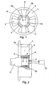
- Figure 1 shows the assembly of a stator 1, a rotor 2 and a ring 3.
- the stator 1 is provided with four recesses 4.
- the rotor is provided with four vanes 5.
- Each of the vanes 5, divide each of the recesses 4 into a first pocket 4a and second pocket 4b.
- the pockets 4a and 4b are capable for receiving fluid, such as oil under pressure.
- Fluid such as oil under pressure.
- An increase of pressure in pocket 4a will move the vane 5 in a direction clockwise with respect to the stator 1.
- An increase in the oil pressure in pockets 4 will move the vane 5 in the opposite direction. That means by controlling the fluid pressure in both pockets 4a, 4b the angular position of the rotor with respect to the stator 1 can be manipulated.
- the control ring 3 comprises four first ring-apertures 6 and four second ring-apertures 7.
- the rotor 2 is provided with four first rotor-apertures 8 and four second rotor-apertures 9.
- first ring-apertures 6 of the control ring 3 are in line with the first rotor-apertures 8 in the rotor 2, a connection is created between the first pocket 4a and a central reservoir 10 for receiving fluid.
- the second ring-apertures 7 of the control ring 3 are in line with the second rotor-apertures 9 of the rotor 2, creating a connection between the pockets 4b and the central reservoir 10 for receiving fluid.
- the control ring 3 does not rotate with the rotor 2, but is rather stationery with respect to the cylinder head. However, its angular position with respect to the camshaft can be adjusted by a drive means, such as a stepper motor.
- the drive means will be controlled, for example, by the engine control unit to position the ring-apertures 6 and 7 relative to the rotor-apertures 8 and 9 in order to ensure that the connection between both the pockets 4a and 4b and the central reservoir for fluid is established at a cam angle that represents a pressure difference between the first pockets 4a and the second pockets 4b.
- the control ring 3 is adjusted so that the pockets 4a and 4b are connected at a time when the pressure in the second pocket 4b is higher than the pressure in the pocket 4a, causing the fluid to flow into the first pocket 4a, and thereby enabling the phasing activity.
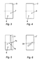
- FIG 2 a side cross sectional view of part of the phaser according to one embodiment of the invention is shown.
- Figure 2 shows the stator 1 which is connected to a timing gear 20.
- the rotor 2 is connected to a camshaft 11, the phaser allowing rotational movement of the camshaft with respect to the timing gear 20.
- drive means 12 are present to control the angular position of the control ring 3 with respect to rotational axis thereof.
- the ring 3 is provided with first ring-apertures 6 and second ring-aperture 7. Those apertures are to be brought in line, at the appropriate time, with the rotor-apertures 8 and 9 in the rotor 2.
- Figure 3 provides a side view of the control ring according to the present invention.
- first ring-apertures 6 are present and second ring-apertures 7.
- Figure 4 provides a top view of the rotor 2 provided with rotor-apertures 8, 9.
- a possible embodiment of the second ring-aperture 7 is shown in Figure 5.
- first ring-aperture 6 with a similar configuration.
- This feature will have the effect that at one of the sets of ring-apertures 6 or 7 is permanently connected to the central cavity 10, comprise a groove 7a in the surface of the ring 3, connected to a through-hole 7b which is connectable to the central recess 10 for receiving fluid (see Figure 2).
- control ring Alternative to an angular adjustment of the control ring, it is possible to use an axial movement of the control ring to move in time the opening and closing of the apertures by the use of a spiral slot or groove in the control ring as will be described in more detail below.
- FIG 6 a second embodiment of the invention is shown wherein the control ring 3' is axially adjustable with respect to the rotor 2 but rotationally fixed with respect to the cylinder head.
- the control ring 3' is provided with a spiral connecting groove 20 providing selective communication between the holes 8 and 9 of the rotor 2.
- the groove 20 provides a shortcut between the holes 8 and 9 as the holes 8,9 of the rotor 2 pass over the groove 20 during rotation of the rotor.
- the use of a groove rather than a slot enables the fluid will be displaced from a first pocket towards a second pocket, via the connecting groove 20 without needing to enter the central reservoir.
- the timing of the passage of the holes 8,9 over the groove 20 can be altered with respect to the cam timing by axially adjusting the position of the control ring 3' with respect to the rotor 2.
Landscapes
- Engineering & Computer Science (AREA)
- Mechanical Engineering (AREA)
- General Engineering & Computer Science (AREA)
- Valve Device For Special Equipments (AREA)
Priority Applications (1)
| Application Number | Priority Date | Filing Date | Title |
|---|---|---|---|
| EP20060254273 EP1757779B1 (fr) | 2005-08-22 | 2006-08-15 | Déphaseur d'arbre à cames pour le contrôle du déphasage entre un arbre à cames et une roue d'entraînement |
Applications Claiming Priority (2)
| Application Number | Priority Date | Filing Date | Title |
|---|---|---|---|
| EP05018206 | 2005-08-22 | ||
| EP20060254273 EP1757779B1 (fr) | 2005-08-22 | 2006-08-15 | Déphaseur d'arbre à cames pour le contrôle du déphasage entre un arbre à cames et une roue d'entraînement |
Publications (3)
| Publication Number | Publication Date |
|---|---|
| EP1757779A2 true EP1757779A2 (fr) | 2007-02-28 |
| EP1757779A3 EP1757779A3 (fr) | 2007-03-07 |
| EP1757779B1 EP1757779B1 (fr) | 2008-11-12 |
Family
ID=37667972
Family Applications (1)
| Application Number | Title | Priority Date | Filing Date |
|---|---|---|---|
| EP20060254273 Not-in-force EP1757779B1 (fr) | 2005-08-22 | 2006-08-15 | Déphaseur d'arbre à cames pour le contrôle du déphasage entre un arbre à cames et une roue d'entraînement |
Country Status (1)
| Country | Link |
|---|---|
| EP (1) | EP1757779B1 (fr) |
Cited By (2)
| Publication number | Priority date | Publication date | Assignee | Title |
|---|---|---|---|---|
| EP2075421A1 (fr) * | 2007-12-28 | 2009-07-01 | Delphi Technologies, Inc. | Soupape de contrôle de fluide pour synchronisateur de phase de cames |
| WO2017180424A1 (fr) * | 2016-04-11 | 2017-10-19 | Borgwarner Inc. | Solénoïde à action rapide à trois positions |
Family Cites Families (9)
| Publication number | Priority date | Publication date | Assignee | Title |
|---|---|---|---|---|
| FR1085087A (fr) * | 1953-06-17 | 1955-01-27 | Dispositif de commande du déplacement angulaire relatif de deux parties co-axiales d'une transmission | |
| US5507254A (en) * | 1989-01-13 | 1996-04-16 | Melchior; Jean F. | Variable phase coupling for the transmission of alternating torques |
| FR2641832B1 (fr) * | 1989-01-13 | 1991-04-12 | Melchior Jean | Accouplement pour la transmission de couples alternes |
| DE3930157A1 (de) * | 1989-09-09 | 1991-03-21 | Bosch Gmbh Robert | Einrichtung zur verstellung der drehwinkelzuordnung einer nockenwelle zu ihrem antriebselement |
| US5107804A (en) * | 1989-10-16 | 1992-04-28 | Borg-Warner Automotive Transmission & Engine Components Corporation | Variable camshaft timing for internal combustion engine |
| US6840202B2 (en) * | 2002-09-03 | 2005-01-11 | Borgwarner Inc. | Method to reduce noise of a cam phaser by controlling the position of center mounted spool valve |
| US6814038B2 (en) * | 2002-09-19 | 2004-11-09 | Borgwarner, Inc. | Spool valve controlled VCT locking pin release mechanism |
| US7137371B2 (en) * | 2003-02-07 | 2006-11-21 | Borgwarner Inc. | Phaser with a single recirculation check valve and inlet valve |
| US6799544B1 (en) * | 2003-05-29 | 2004-10-05 | Delphi Technologies, Inc. | Method and apparatus for actuating a cam phaser |
-
2006
- 2006-08-15 EP EP20060254273 patent/EP1757779B1/fr not_active Not-in-force
Cited By (3)
| Publication number | Priority date | Publication date | Assignee | Title |
|---|---|---|---|---|
| EP2075421A1 (fr) * | 2007-12-28 | 2009-07-01 | Delphi Technologies, Inc. | Soupape de contrôle de fluide pour synchronisateur de phase de cames |
| WO2017180424A1 (fr) * | 2016-04-11 | 2017-10-19 | Borgwarner Inc. | Solénoïde à action rapide à trois positions |
| US10400909B2 (en) | 2016-04-11 | 2019-09-03 | Borgwarner Inc. | Three position fast acting solenoid |
Also Published As
| Publication number | Publication date |
|---|---|
| EP1757779A3 (fr) | 2007-03-07 |
| EP1757779B1 (fr) | 2008-11-12 |
Similar Documents
| Publication | Publication Date | Title |
|---|---|---|
| US7523728B2 (en) | Phaser for controlling the timing between a camshaft and a timing gear | |
| JP4209152B2 (ja) | 位相器 | |
| EP1286023B1 (fr) | Déphaseur pour un moteur à combustion interne à quatre cylindre | |
| EP2337932B1 (fr) | Dispositif de mise en phase incorpore dans un arbre a cames ou des arbres a cames concentriques | |
| CN102439265B (zh) | 用于内燃机的移相器组件 | |
| US5205249A (en) | Variable camshaft timing system for internal combustion engine utilizing flywheel energy for reduced camshaft torsionals | |
| US9284861B2 (en) | Oil passage design for a phaser or dual phaser | |
| GB2369175A (en) | Variable phase coupling | |
| CN102112707A (zh) | 用于可变地调整内燃机换气阀的配气正时的装置 | |
| US9103240B2 (en) | Camshaft adjuster | |
| EP1359291A1 (fr) | Amortissement hydraulique pour un mechanisme des soupapes variables | |
| EP1761684B1 (fr) | Moteur a reglage de distribution variable | |
| CN107208505A (zh) | 凸轮轴调相器 | |
| US9080470B2 (en) | Shared oil passages and/or control valve for one or more cam phasers | |
| EP1757779A2 (fr) | Déphaseur d'arbre à cames pour le contrôle du déphasage entre un arbre à cames et une roue d'entraînement | |
| EP1956200A2 (fr) | Dispositif de commande de soupape doté d'un calage et d'une durée de levée de soupape variable | |
| CN108350768B (zh) | 凸轮轴调节设备 | |
| US20060096562A1 (en) | Reed valve with multiple ports | |
| KR20120089281A (ko) | 캠 샤프트 장치 | |
| CN110998070B (zh) | 用于凸轮轴正时调节的具有内置泵的设备 | |
| US11905861B2 (en) | Multi-camshaft phase adjusting system | |
| EP1734233A2 (fr) | Came hydraulique pour commande variable de soupape | |
| JPH09151711A (ja) | 弁開閉時期制御装置 | |
| EP2915964A1 (fr) | Moteur à combustion interne | |
| JP2002097909A (ja) | 内燃機関のバルブタイミング制御装置 |
Legal Events
| Date | Code | Title | Description |
|---|---|---|---|
| PUAI | Public reference made under article 153(3) epc to a published international application that has entered the european phase |
Free format text: ORIGINAL CODE: 0009012 |
|
| PUAL | Search report despatched |
Free format text: ORIGINAL CODE: 0009013 |
|
| AK | Designated contracting states |
Kind code of ref document: A2 Designated state(s): AT BE BG CH CY CZ DE DK EE ES FI FR GB GR HU IE IS IT LI LT LU LV MC NL PL PT RO SE SI SK TR |
|
| AX | Request for extension of the european patent |
Extension state: AL BA HR MK YU |
|
| AK | Designated contracting states |
Kind code of ref document: A3 Designated state(s): AT BE BG CH CY CZ DE DK EE ES FI FR GB GR HU IE IS IT LI LT LU LV MC NL PL PT RO SE SI SK TR |
|
| AX | Request for extension of the european patent |
Extension state: AL BA HR MK YU |
|
| 17P | Request for examination filed |
Effective date: 20070312 |
|
| 17Q | First examination report despatched |
Effective date: 20070413 |
|
| AKX | Designation fees paid |
Designated state(s): AT BE BG CH CY CZ DE DK EE ES FI FR GB GR HU IE IS IT LI LT LU LV MC NL PL PT RO SE SI SK TR |
|
| GRAP | Despatch of communication of intention to grant a patent |
Free format text: ORIGINAL CODE: EPIDOSNIGR1 |
|
| GRAS | Grant fee paid |
Free format text: ORIGINAL CODE: EPIDOSNIGR3 |
|
| GRAA | (expected) grant |
Free format text: ORIGINAL CODE: 0009210 |
|
| AK | Designated contracting states |
Kind code of ref document: B1 Designated state(s): AT BE BG CH CY CZ DE DK EE ES FI FR GB GR HU IE IS IT LI LT LU LV MC NL PL PT RO SE SI SK TR |
|
| REG | Reference to a national code |
Ref country code: GB Ref legal event code: FG4D |
|
| REG | Reference to a national code |
Ref country code: CH Ref legal event code: EP |
|
| REG | Reference to a national code |
Ref country code: IE Ref legal event code: FG4D |
|
| REF | Corresponds to: |
Ref document number: 602006003600 Country of ref document: DE Date of ref document: 20081224 Kind code of ref document: P |
|
| LTIE | Lt: invalidation of european patent or patent extension |
Effective date: 20081112 |
|
| PG25 | Lapsed in a contracting state [announced via postgrant information from national office to epo] |
Ref country code: AT Free format text: LAPSE BECAUSE OF FAILURE TO SUBMIT A TRANSLATION OF THE DESCRIPTION OR TO PAY THE FEE WITHIN THE PRESCRIBED TIME-LIMIT Effective date: 20081112 Ref country code: LT Free format text: LAPSE BECAUSE OF FAILURE TO SUBMIT A TRANSLATION OF THE DESCRIPTION OR TO PAY THE FEE WITHIN THE PRESCRIBED TIME-LIMIT Effective date: 20081112 Ref country code: ES Free format text: LAPSE BECAUSE OF FAILURE TO SUBMIT A TRANSLATION OF THE DESCRIPTION OR TO PAY THE FEE WITHIN THE PRESCRIBED TIME-LIMIT Effective date: 20090223 |
|
| NLV1 | Nl: lapsed or annulled due to failure to fulfill the requirements of art. 29p and 29m of the patents act | ||
| PG25 | Lapsed in a contracting state [announced via postgrant information from national office to epo] |
Ref country code: IS Free format text: LAPSE BECAUSE OF FAILURE TO SUBMIT A TRANSLATION OF THE DESCRIPTION OR TO PAY THE FEE WITHIN THE PRESCRIBED TIME-LIMIT Effective date: 20090312 Ref country code: LV Free format text: LAPSE BECAUSE OF FAILURE TO SUBMIT A TRANSLATION OF THE DESCRIPTION OR TO PAY THE FEE WITHIN THE PRESCRIBED TIME-LIMIT Effective date: 20081112 Ref country code: PL Free format text: LAPSE BECAUSE OF FAILURE TO SUBMIT A TRANSLATION OF THE DESCRIPTION OR TO PAY THE FEE WITHIN THE PRESCRIBED TIME-LIMIT Effective date: 20081112 Ref country code: FI Free format text: LAPSE BECAUSE OF FAILURE TO SUBMIT A TRANSLATION OF THE DESCRIPTION OR TO PAY THE FEE WITHIN THE PRESCRIBED TIME-LIMIT Effective date: 20081112 Ref country code: SI Free format text: LAPSE BECAUSE OF FAILURE TO SUBMIT A TRANSLATION OF THE DESCRIPTION OR TO PAY THE FEE WITHIN THE PRESCRIBED TIME-LIMIT Effective date: 20081112 Ref country code: NL Free format text: LAPSE BECAUSE OF FAILURE TO SUBMIT A TRANSLATION OF THE DESCRIPTION OR TO PAY THE FEE WITHIN THE PRESCRIBED TIME-LIMIT Effective date: 20081112 |
|
| PG25 | Lapsed in a contracting state [announced via postgrant information from national office to epo] |
Ref country code: DK Free format text: LAPSE BECAUSE OF FAILURE TO SUBMIT A TRANSLATION OF THE DESCRIPTION OR TO PAY THE FEE WITHIN THE PRESCRIBED TIME-LIMIT Effective date: 20081112 Ref country code: BE Free format text: LAPSE BECAUSE OF FAILURE TO SUBMIT A TRANSLATION OF THE DESCRIPTION OR TO PAY THE FEE WITHIN THE PRESCRIBED TIME-LIMIT Effective date: 20081112 Ref country code: EE Free format text: LAPSE BECAUSE OF FAILURE TO SUBMIT A TRANSLATION OF THE DESCRIPTION OR TO PAY THE FEE WITHIN THE PRESCRIBED TIME-LIMIT Effective date: 20081112 Ref country code: BG Free format text: LAPSE BECAUSE OF FAILURE TO SUBMIT A TRANSLATION OF THE DESCRIPTION OR TO PAY THE FEE WITHIN THE PRESCRIBED TIME-LIMIT Effective date: 20090212 Ref country code: RO Free format text: LAPSE BECAUSE OF FAILURE TO SUBMIT A TRANSLATION OF THE DESCRIPTION OR TO PAY THE FEE WITHIN THE PRESCRIBED TIME-LIMIT Effective date: 20081112 |
|
| PG25 | Lapsed in a contracting state [announced via postgrant information from national office to epo] |
Ref country code: SE Free format text: LAPSE BECAUSE OF FAILURE TO SUBMIT A TRANSLATION OF THE DESCRIPTION OR TO PAY THE FEE WITHIN THE PRESCRIBED TIME-LIMIT Effective date: 20090212 Ref country code: PT Free format text: LAPSE BECAUSE OF FAILURE TO SUBMIT A TRANSLATION OF THE DESCRIPTION OR TO PAY THE FEE WITHIN THE PRESCRIBED TIME-LIMIT Effective date: 20090413 Ref country code: CZ Free format text: LAPSE BECAUSE OF FAILURE TO SUBMIT A TRANSLATION OF THE DESCRIPTION OR TO PAY THE FEE WITHIN THE PRESCRIBED TIME-LIMIT Effective date: 20081112 |
|
| PLBE | No opposition filed within time limit |
Free format text: ORIGINAL CODE: 0009261 |
|
| STAA | Information on the status of an ep patent application or granted ep patent |
Free format text: STATUS: NO OPPOSITION FILED WITHIN TIME LIMIT |
|
| PG25 | Lapsed in a contracting state [announced via postgrant information from national office to epo] |
Ref country code: SK Free format text: LAPSE BECAUSE OF FAILURE TO SUBMIT A TRANSLATION OF THE DESCRIPTION OR TO PAY THE FEE WITHIN THE PRESCRIBED TIME-LIMIT Effective date: 20081112 |
|
| 26N | No opposition filed |
Effective date: 20090813 |
|
| PG25 | Lapsed in a contracting state [announced via postgrant information from national office to epo] |
Ref country code: MC Free format text: LAPSE BECAUSE OF NON-PAYMENT OF DUE FEES Effective date: 20090831 |
|
| PG25 | Lapsed in a contracting state [announced via postgrant information from national office to epo] |
Ref country code: IE Free format text: LAPSE BECAUSE OF NON-PAYMENT OF DUE FEES Effective date: 20090815 |
|
| PG25 | Lapsed in a contracting state [announced via postgrant information from national office to epo] |
Ref country code: GR Free format text: LAPSE BECAUSE OF FAILURE TO SUBMIT A TRANSLATION OF THE DESCRIPTION OR TO PAY THE FEE WITHIN THE PRESCRIBED TIME-LIMIT Effective date: 20090213 |
|
| REG | Reference to a national code |
Ref country code: CH Ref legal event code: PL |
|
| PG25 | Lapsed in a contracting state [announced via postgrant information from national office to epo] |
Ref country code: LI Free format text: LAPSE BECAUSE OF NON-PAYMENT OF DUE FEES Effective date: 20100831 Ref country code: LU Free format text: LAPSE BECAUSE OF NON-PAYMENT OF DUE FEES Effective date: 20090815 Ref country code: CH Free format text: LAPSE BECAUSE OF NON-PAYMENT OF DUE FEES Effective date: 20100831 |
|
| PG25 | Lapsed in a contracting state [announced via postgrant information from national office to epo] |
Ref country code: HU Free format text: LAPSE BECAUSE OF FAILURE TO SUBMIT A TRANSLATION OF THE DESCRIPTION OR TO PAY THE FEE WITHIN THE PRESCRIBED TIME-LIMIT Effective date: 20090513 |
|
| PG25 | Lapsed in a contracting state [announced via postgrant information from national office to epo] |
Ref country code: TR Free format text: LAPSE BECAUSE OF FAILURE TO SUBMIT A TRANSLATION OF THE DESCRIPTION OR TO PAY THE FEE WITHIN THE PRESCRIBED TIME-LIMIT Effective date: 20081112 |
|
| PG25 | Lapsed in a contracting state [announced via postgrant information from national office to epo] |
Ref country code: CY Free format text: LAPSE BECAUSE OF FAILURE TO SUBMIT A TRANSLATION OF THE DESCRIPTION OR TO PAY THE FEE WITHIN THE PRESCRIBED TIME-LIMIT Effective date: 20081112 |
|
| REG | Reference to a national code |
Ref country code: FR Ref legal event code: PLFP Year of fee payment: 10 |
|
| REG | Reference to a national code |
Ref country code: FR Ref legal event code: PLFP Year of fee payment: 11 |
|
| REG | Reference to a national code |
Ref country code: FR Ref legal event code: PLFP Year of fee payment: 12 |
|
| REG | Reference to a national code |
Ref country code: FR Ref legal event code: PLFP Year of fee payment: 13 |
|
| PGFP | Annual fee paid to national office [announced via postgrant information from national office to epo] |
Ref country code: DE Payment date: 20180829 Year of fee payment: 13 Ref country code: IT Payment date: 20180822 Year of fee payment: 13 Ref country code: FR Payment date: 20180827 Year of fee payment: 13 |
|
| PGFP | Annual fee paid to national office [announced via postgrant information from national office to epo] |
Ref country code: GB Payment date: 20180828 Year of fee payment: 13 |
|
| REG | Reference to a national code |
Ref country code: DE Ref legal event code: R119 Ref document number: 602006003600 Country of ref document: DE |
|
| GBPC | Gb: european patent ceased through non-payment of renewal fee |
Effective date: 20190815 |
|
| PG25 | Lapsed in a contracting state [announced via postgrant information from national office to epo] |
Ref country code: DE Free format text: LAPSE BECAUSE OF NON-PAYMENT OF DUE FEES Effective date: 20200303 Ref country code: FR Free format text: LAPSE BECAUSE OF NON-PAYMENT OF DUE FEES Effective date: 20190831 |
|
| PG25 | Lapsed in a contracting state [announced via postgrant information from national office to epo] |
Ref country code: IT Free format text: LAPSE BECAUSE OF NON-PAYMENT OF DUE FEES Effective date: 20190815 Ref country code: GB Free format text: LAPSE BECAUSE OF NON-PAYMENT OF DUE FEES Effective date: 20190815 |