EP1757757B1 - Schließzylinder mit Fliehkraftbremse - Google Patents
Schließzylinder mit Fliehkraftbremse Download PDFInfo
- Publication number
- EP1757757B1 EP1757757B1 EP06114998A EP06114998A EP1757757B1 EP 1757757 B1 EP1757757 B1 EP 1757757B1 EP 06114998 A EP06114998 A EP 06114998A EP 06114998 A EP06114998 A EP 06114998A EP 1757757 B1 EP1757757 B1 EP 1757757B1
- Authority
- EP
- European Patent Office
- Prior art keywords
- lock cylinder
- brake
- cylinder according
- shaft
- handle
- Prior art date
- Legal status (The legal status is an assumption and is not a legal conclusion. Google has not performed a legal analysis and makes no representation as to the accuracy of the status listed.)
- Not-in-force
Links
- 230000000903 blocking effect Effects 0.000 claims description 9
- 230000004913 activation Effects 0.000 description 3
- 230000005672 electromagnetic field Effects 0.000 description 3
- 230000008878 coupling Effects 0.000 description 2
- 238000010168 coupling process Methods 0.000 description 2
- 238000005859 coupling reaction Methods 0.000 description 2
- 238000007373 indentation Methods 0.000 description 2
- 239000000463 material Substances 0.000 description 2
- 229910000760 Hardened steel Inorganic materials 0.000 description 1
- 230000000694 effects Effects 0.000 description 1
- 230000002401 inhibitory effect Effects 0.000 description 1
- 239000002184 metal Substances 0.000 description 1
Images



Classifications
-
- E—FIXED CONSTRUCTIONS
- E05—LOCKS; KEYS; WINDOW OR DOOR FITTINGS; SAFES
- E05B—LOCKS; ACCESSORIES THEREFOR; HANDCUFFS
- E05B17/00—Accessories in connection with locks
- E05B17/20—Means independent of the locking mechanism for preventing unauthorised opening, e.g. for securing the bolt in the fastening position
- E05B17/2084—Means to prevent forced opening by attack, tampering or jimmying
- E05B17/2092—Means responsive to tampering or attack providing additional locking
-
- E—FIXED CONSTRUCTIONS
- E05—LOCKS; KEYS; WINDOW OR DOOR FITTINGS; SAFES
- E05B—LOCKS; ACCESSORIES THEREFOR; HANDCUFFS
- E05B15/00—Other details of locks; Parts for engagement by bolts of fastening devices
- E05B15/0093—Weight arrangements in locks; gravity activated lock parts
-
- E—FIXED CONSTRUCTIONS
- E05—LOCKS; KEYS; WINDOW OR DOOR FITTINGS; SAFES
- E05B—LOCKS; ACCESSORIES THEREFOR; HANDCUFFS
- E05B47/00—Operating or controlling locks or other fastening devices by electric or magnetic means
- E05B47/06—Controlling mechanically-operated bolts by electro-magnetically-operated detents
- E05B47/0611—Cylinder locks with electromagnetic control
- E05B47/0615—Cylinder locks with electromagnetic control operated by handles, e.g. by knobs
-
- E—FIXED CONSTRUCTIONS
- E05—LOCKS; KEYS; WINDOW OR DOOR FITTINGS; SAFES
- E05B—LOCKS; ACCESSORIES THEREFOR; HANDCUFFS
- E05B47/00—Operating or controlling locks or other fastening devices by electric or magnetic means
- E05B47/06—Controlling mechanically-operated bolts by electro-magnetically-operated detents
- E05B47/0611—Cylinder locks with electromagnetic control
- E05B47/0638—Cylinder locks with electromagnetic control by disconnecting the rotor
-
- E—FIXED CONSTRUCTIONS
- E05—LOCKS; KEYS; WINDOW OR DOOR FITTINGS; SAFES
- E05B—LOCKS; ACCESSORIES THEREFOR; HANDCUFFS
- E05B27/00—Cylinder locks or other locks with tumbler pins or balls that are set by pushing the key in
- E05B27/0057—Cylinder locks or other locks with tumbler pins or balls that are set by pushing the key in with increased picking resistance
- E05B27/006—Cylinder locks or other locks with tumbler pins or balls that are set by pushing the key in with increased picking resistance whereby a small rotation without the correct key blocks further rotation of the rotor
Definitions
- the invention relates to a lock cylinder with a lock cylinder housing, a closure member and a rotary handle which is normally freely rotatably mounted on the lock cylinder housing and is only rotationally coupled to the closure member when a key query has found a suitable key.
- Such a lock cylinder is for example from the document DE 198 51 308 A1 known in the art.
- the outer handle turns empty when the key is not in place.
- the shaft connected to the outer handle lies in a bearing cavity of the lock cylinder and extends through the entire length of the lock cylinder into an inner handle.
- the outer handle rotatably connected shaft in a cavity of a hollow shaft which is rotatably connected to the inner handle and the closing member.
- In the inner handle is a coupling that connects the core of the shaft with the hollow shaft, if a matching key is detected.
- the friction between the core shaft and the hollow shaft increases in such a way that the closing member is entrained.
- the invention provides the solution specified in claim 1.
- the rotary handle is associated with a brake, which rotates with the rotary handle. At a rotational speed exceeding a limiting rotational speed of the handle, the brake occurs in at least rotationally inhibiting effect.
- the brake is preferably a centrifugal brake. In a further preferred embodiment, the brake is able not only to slow down or inhibit the rotational movement of the rotary handle, but to stop.
- the brake can be assigned to a shaft mounted in the cylinder housing.
- the brake may include a brake arm held in a passive position by a spring. Due to the centrifugal force occurring at high speeds, the spring force can be overcome. Then the brake arm occurs radially.
- the bearing cavity of the shaft preferably has a stop.
- This stop can be formed by a wall of a bore which is located in the profile section of the lock cylinder housing. Against this wall portion or a differently shaped stop, the brake arm or a blocking portion formed by the brake arm can occur when the brake arm pivots radially outward in a centrifugal-force-driven manner.
- two brake arms are provided, which are arranged mirror-symmetrically such that they can be effective both in left and in the right direction of rotation of the rotary handle.
- the two brake arms are preferably held by a C-shaped leaf spring in its passive position.
- the swivel angle is stop-limited.
- the lock cylinder according to the invention can be closed with mechanical keys.
- the lock cylinder cooperates with electronic keys and in particular with transponder keys, which can be read out wirelessly via electromagnetic waves; for this purpose, an antenna and a switch are preferably located in the outer handle. Switch and antenna are connected via a line, which is guided by the shaft, with an electronic circuit, which is located in the inner knob. The electronic circuit can be activated via the switch. To emit an alternating electromagnetic field at a suitable frequency. This alternating electromagnetic field is received by the transponder. The transponder is thereby excited and in particular supplied with energy in order to transmit its identifier to the antenna. The identifier is from the antenna or the in the inner handle sitting electronic circuit received and evaluated.
- the identifier is issued as reading permission from the transponder only after a previous identification of the lock cylinder. If the electronic circuit determines that the lock cylinder is authorized to lock due to the identifier issued by it, then the outside turning handle is coupled to the closing member. This can be done in a manner as already described in the prior art.
- the coupling may be arranged in the rotary inner handle into which the shaft rotatably connected to the outer handle protrudes.
- the inner handle is in turn rotatably coupled via a hollow shaft with the closing member.
- the inner handle is always coupled, the outer handle but only with a matching key with the closing member.
- the outer handle is screwed by means of fastening screws with the end face of the shaft.
- the fastening screws are screwed into threaded inserts. These threaded inserts stuck in the end face of the shaft. When an axial limit force is applied to the threaded inserts, the threaded inserts either break out of the end face of the shaft or break off. In a preferred embodiment, these threaded inserts are made of a softer material than the material of the shaft.
- the threaded inserts can have axial extensions, which form the pivot bearings for the brake arms.
- the threaded inserts form threaded sockets lying in front of the end face of the shaft.
- two threaded inserts are provided which are interconnected via a web.
- the lock cylinder is a double lock cylinder. It has an outer handle 3 and an inner handle 18. Between inner handle 18 and outer handle 3 is a cylinder housing 1, which is a profile cylinder housing. This has in the middle a closing member 2, which can be pivoted by turning the inner handle 18 to open or close a lock, in which the lock cylinder is inserted.
- the inner rotary handle 18 is rotationally coupled via a hollow shaft with the closing member 2.
- an electronic circuit not shown, and batteries are arranged.
- a clutch located in the inner handle a clutch, not shown, to lubzukuppeln the inner handle or the hollow shaft driven by it with a core shaft which is rotatably connected to the outer handle 3.
- This core shaft 9 is located in a bearing cavity 10, which is located in both halves of the cylinder housing 1 and extends through the closure member 2.
- the outer rotating handle 3 can be emptied without the closing member 2 is dragged. This is moved by unidentified matching key exclusively from the inner handle 18.
- the outer handle 3 In the outer handle 3 is an antenna, not shown, and an activation switch.
- the antenna and the activation switch are connected via a cable, which is guided by a cable slot 18 of the shaft 9, with the electronic circuit which is arranged in the inner knob 18. If the activation switch is actuated, the antenna transmits an alternating electromagnetic field which supplies the transponder held in front of the front side of the external handle 3 with energy. This then sends its identifier, which is received by the antenna.
- the clutch If the electronic circuit detects that it is a suitable key, the clutch, not shown, is put into operation, which then couples the shaft 9 with the inner handle 18 or the hollow shaft, not shown, so that the outer handle 3 is rotatably connected to the closing member is. If the rotary handle 3 is now rotated, then the closing member 2 is dragged along. A lock, in which the lock cylinder is inserted, can thus be opened or closed by the external handle when the correct key is detected.
- the invention provides a centrifugal brake 4 before. This occurs at speeds between 900 and 1200 revolutions per minute in effect and stops the rotation of the outer handle.
- the structure of the centrifugal brake can be especially the Figures 2 and 3 remove. There it can be seen that the shaft 9 forms two diametrically opposed radial recesses, between which a connecting web 16 extends.
- brake arms 5 which are made of metal.
- the brake arm 5 is rotatably arranged in the recesses by means of a pivot bearing 13. He has a short end, which forms a stop edge 14.
- the long end of the brake arm 5 forms a blocking portion 11. This blocking portion 11 is located at the end of the brake arm 5.
- the brake arm also forms an indentation 12, on which a spring 6 engages.
- the spring 6 is formed as a C-shaped spring clip, with successively directed end webs 6 ', which rest on the bottom of the recess 12.
- the indentations 12 are in the region of the long arm of the brake arm 5.
- the symmetrical arrangement of the brake arms 5 is advantageous since the said C-shaped spring clip can be used here.
- the two mutually pioneering Schmidtflanken 15, which are formed by the connecting web 16, extend wedge-shaped to each other.
- a bore 8 is provided in the profile section of the cylinder housing 1.
- the opening into the bearing cavity 10 for the shaft 9 wall 8 forms a stop 7 for the blocking portion 11 of the brake arm 5.
- an insert body 18 made of a hardened steel.
- the shaft 9 has a circumferential groove 21, into which a shaft fastening screw 20 engages in order to support the shaft 9 in a tensile strength in the cavity 10.
- a threaded insert 22 is introduced in the front side 9 'of the shaft 9.
- the threaded insert 22 has two internal threads for screwing in the fastening screws 24 with which the outer rotary handle 3 is connected to the end face 9 'of the shaft 9.
- the two threaded bushes thus formed are connected to each other via a web and have axial extensions 13, which form the pivot bearing for the arms 5.
- the threaded inserts 22 form over the end face 9 'of the shaft 9 projecting threaded socket 23, which protrude into mounting holes 25 a mounting wall of the rotary handle.
- the head of the fastening screw 24 lies on the inside of the fastening wall and thus holds the rotary handle 3 on the shaft 9.
- the threaded portions of the fastening screw 24 preferably project only into the portion of the internal thread which is formed by the threaded base 23. But they can also be screwed deeper into the internal thread.
- the operation of the lock cylinder is the following:
- the brake arms remain 5 in their in the FIG. 2 represented passive position.
- the blocking sections 11 lie in contact with the narrow end of the connecting web 16. They are acted upon by the force of the spring clip 6 there. The centrifugal forces occurring in the normal rotational movements are not sufficient to shift the brake arms 5.
- the rotary handle can be stopped in both a left-hand rotation and a clockwise rotation when the limit torque is exceeded. In this case, enters the pivoted into the bore 8 blocking portion 11 of the brake arm 5 against the wall 7 of the bore, which forms a stop. The rotary handle 3 then stops abruptly. Immediately thereafter, the shaft 9 blocking the brake arm 5 is swung back by the force of the spring 6 back into the passive position.
- the fastening screws 24 tear the threaded inserts 22 out of their fastening cavities, since the threaded inserts 22 are merely glued in there or are positively connected therein. If the fastening screws 24 protrude only into the region of the threaded base 23, this will be torn off.
Landscapes
- Physics & Mathematics (AREA)
- Electromagnetism (AREA)
- Braking Arrangements (AREA)
Description
- Die Erfindung betrifft einen Schließzylinder mit einem Schließzylindergehäuse, einem Schließglied und einer Drehhandhabe, welche normalerweise frei drehbar am Schließzylindergehäuse gelagert ist und nur dann mit dem Schließglied drehgekoppelt ist, wenn eine Schlüsselabfrage einen passenden Schlüssel festgestellt hat.
- Ein derartiger Schließzylinder ist zum Beispiel aus dem Dokument
DE 198 51 308 A1 im Stand der Technik bekannt. Die Außenhandhabe dreht bei nicht passendem Schlüssel leer. Die mit der Außenhandhabe verbundene Welle liegt in einer Lagerhöhlung des Schließzylinders und durchgreift die gesamte Länge des Schließzylinders bis in eine Innenhandhabe. Im Bereich der der Innenhandhabe zugeordneten Hälfte des Schließzylinders liegt diese, mit der Außenhandhabe drehfest verbundene Welle in einer Höhlung einer Hohlwelle, die drehfest mit der Innenhandhabe und dem Schließglied verbunden ist. In der Innenhandhabe befindet sich eine Kupplung, die den Kern der Welle mit der Hohlwelle verbindet, wenn ein passender Schlüssel festgestellt wird. Bei sehr hohen Drehzahlen, die bspw. mit einem Elektromotor auf die Außenhandhabe aufgebracht werden, steigt die Reibung zwischen der Kernwelle und der Hohlwelle derart an, dass das Schließglied mitgeschleppt wird. Um zu vermeiden, dass dabei ein Schloss in unzulässiger Weise von der Außenhandhabe geöffnet wird, sieht die Erfindung die im Anspruch 1 angegebene Lösung vor. - Zunächst und im Wesentlichen ist vorgesehen, dass die Drehhandhabe einer Bremse zugeordnet ist, die mit der Drehhandhabe mitdreht. Bei einer eine Grenzdrehzahl überschreitenden Drehzahl der Drehhandhabe tritt die Bremse in zumindest drehhemmende Wirkung. Die Bremse ist bevorzugt eine Fliehkraftbremse. In einer weiter bevorzugten Ausgestaltung ist die Bremse in der Lage, die Drehbewegung der Drehhandhabe nicht nur zu verlangsamen oder zu hemmen, sondern zu stoppen. Die Bremse kann einer im Zylindergehäuse gelagerten Welle zugeordnet sein. Die Bremse kann einen Bremsarm aufweisen, der von einer Feder in einer passiven Lage gehalten ist. Zufolge der bei hohen Drehzahlen auftretenden Fliehkraft kann die Federkraft überwunden werden. Dann tritt der Bremsarm radial vor. Die Lagerhöhlung der Welle weist bevorzugt einen Anschlag auf. Dieser Anschlag kann von einer Wandung einer Bohrung ausgebildet werden, die sich im Profilabschnitt des Schließzylindergehäuses befindet. Gegen diesen Wandabschnitt oder einen andersgestalteten Anschlag kann der Bremsarm bzw. ein vom Bremsarm ausgebildeter Blockierabschnitt treten, wenn der Bremsarm fliehkraftgetrieben radial nach außen schwenkt. In einer bevorzugten Ausgestaltung der Erfindung sind zwei Bremsarme vorgesehen, die derart spiegelsymmetrisch angeordnet sind, dass sie sowohl in Links- als auch in Rechtsdrehrichtung der Drehhandhabe in Wirkung treten können. Die beiden Bremsarme werden vorzugsweise von einer C-förmig gebogenen Blattfeder in ihrer passiven Stellung gehalten. Bei den Bremsarmen ist der Ausschwenkwinkel anschlagbegrenzt. Der erfindungsgemäße Schließzylinder kann mit mechanischen Schlüsseln geschlossen werden. Bevorzugt wirkt der Schließzylinder aber mit elektronischen Schlüsseln und insbesondere mit Transponderschlüsseln zusammen, die drahtlos über elektromagnetische Wellen ausgelesen werden können, hierzu sitzt vorzugsweise in der Außenhandhabe eine Antenne und ein Schalter. Schalter und Antenne sind über eine Leitung, die durch die Welle geführt ist, mit einer elektronischen Schaltung verbunden, die sich im Innenknauf befindet. Über den Schalter kann die elektronische Schaltung aktiviert werden. Ein elektromagnetisches Wechselfeld in einer geeigneten Frequenz abzusenden. Dieses elektromagnetische Wechselfeld wird vom Transponder empfangen. Der Transponder wird dadurch angeregt und insbesondere mit Energie versorgt, um seine Kennung an die Antenne abzusenden. Die Kennung wird von der Antenne bzw. von der in der Innenhandhabe sitzenden elektronischen Schaltung empfangen und ausgewertet. Es ist insbesondere vorgesehen, dass die Kennung nur nach einer zuvorigen Identifizierung des Schließzylinders als leseberechtigt vom Transponder abgegeben wird. Stellt die elektronische Schaltung fest, dass der Schließzylinder aufgrund der von ihm abgegebenen Kennung schließberechtigt ist, so wird die Außendrehhandhabe mit dem Schließglied gekuppelt. Dies kann auf eine Art und Weise erfolgen, wie sie bereits im Stand der Technik beschrieben ist. Beispielsweise kann die Kupplung in der Drehinnenhandhabe angeordnet sein, in die die drehfest mit der Außenhandhabe verbundene Welle ragt. Die Innenhandhabe ist wiederum über eine Hohlwelle drehfest mit dem Schließglied gekuppelt. Dadurch ist die Innenhandhabe immer, die Außenhandhabe aber nur bei passendem Schlüssel mit dem Schließglied gekuppelt.
- In einer Weiterbildung der Erfindung ist vorgesehen, dass die Außenhandhabe über Befestigungsschrauben mit der Stirnfläche der Welle verschraubt ist. Zur Erhöhung der Sicherheit des Schließzylinders wird dort vorgesehen, dass die Befestigungsschrauben in Gewindeeinsätze eingeschraubt sind. Diese Gewindeeinsätze stecken in der Stirnfläche der Welle. Bei Überschreiten einer axialen Grenzkraft, die auf die Gewindeeinsätze aufgebracht wird, reißen die Gewindeeinsätze entweder aus der Stirnfläche der Welle heraus oder brechen ab. In einer bevorzugten Ausgestaltung sind diese Gewindeeinsätze aus weicherem Material, als das Material der Welle. Die Gewindeeinsätze können axial Fortsätze aufweisen, die die Drehlager für die Bremsarme ausbilden. Ferner kann vorgesehen sein, dass die Gewindeeinsätze Gewindesockel ausbilden, die vor der Stirnfläche der Welle liegen. Bevorzugt reißen genau diese Gewindesockel ab, wenn auf die Gewindeeinsätze eine hohe Zugkraft ausgeübt wird. Bevorzugt sind zwei Gewindeeinsätze vorgesehen, die über einen Steg miteinander verbunden sind.
- Ein Ausführungsbeispiel der Erfindung wird nachfolgend anhand beigefügter Zeichnungen erläutert. Es zeigen:
- Fig.1
- die Ansicht eines Schließzylinders mit teilweise geschnittenem Zylindergehäuse und Außenhandhabe in einer aktiven Stellung der Bremse,
- Fig. 2
- einen Schnitt gemäß der Linie II-II in
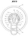
Fig.1 durch die Fliehkraftbremse 4, - Fig. 3
- eine Darstellung gemäß
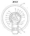
Fig. 2 jedoch nicht in der aktiven Bremsstellung, sondern in einer passiven Bremsstellung, - Fig. 4
- eine Darstellung gemäß
Fig.1 , jedoch in der passiven Bremsstellung, - Fig. 5
- eine perspektivische Darstellung des teilgeschnittenen Schließzylinders und
- Fig. 6
- eine vergrößerte Schnittdarstellung der Verbindungsstelle der Drehhandhabe mit der Welle.
- Bei dem Schließzylinder handelt es sich um einen Doppelschließzylinder. Er besitzt einen Außenhandhabe 3 und eine Innenhandhabe 18. Zwischen Innenhandhabe 18 und Außenhandhabe 3 befindet sich ein Zylindergehäuse 1, bei dem es sich um ein Profilzylindergehäuse handelt. Dieses besitzt in der Mitte ein Schließglied 2, welches durch Drehen der Innenhandhabe 18 verschwenkt werden kann, um ein Schloss, in welches der Schließzylinder eingesetzt ist, zu öffnen oder zu schließen. Die Innendrehhandhabe 18 ist über eine Hohlwelle mit dem Schließglied 2 drehgekoppelt. Innerhalb der Innenhandhabe 18 ist eine nicht dargestellte elektronische Schaltung und sind Batterien angeordnet. Darüber hinaus befindet sich in der Innenhandhabe eine nicht dargestellte Kupplung, um die Innenhandhabe bzw. die von ihr angetriebene Hohlwelle mit einer Kernwelle drehzukuppeln, die drehfest mit der Außenhandhabe 3 verbunden ist. Diese Kernwelle 9 liegt in einer Lagerhöhlung 10, die sich in beiden Hälften des Zylindergehäuses 1 befindet und durchragt das Schließglied 2. Bei nicht betätigter Kupplung kann die Außendrehhandhabe 3 leergedreht werden, ohne dass das Schließglied 2 mitgeschleppt wird. Dieses wird bei nicht erkanntem passenden Schlüssel ausschließlich von der Innenhandhabe 18 bewegt.
- In der Außenhandhabe 3 befindet sich eine nicht dargestellte Antenne und ein Aktivierungsschalter. Die Antenne und der Aktivierungsschalter sind über ein Kabel, welches durch einen Kabelschlitz 18 der Welle 9 geführt ist, mit der elektronischen Schaltung verbunden, die im Innenknauf 18 angeordnet ist. Wird der Aktivierungsschalter betätigt, so sendet die Antenne ein elektromagnetisches Wechselfeld aus, das den vor die Stirnseite der Außenhandhabe 3 gehaltenen Transponder mit Energie versorgt. Dieser sendet dann seine Kennung ab, die von der Antenne empfangen wird. Erkennt die elektronische Schaltung, dass es sich um einen passenden Schlüssel handelt, so wird die nicht dargestellte Kupplung in Betrieb gesetzt, die sodann die Welle 9 mit der Innenhandhabe 18 bzw. der nicht dargestellten Hohlwelle kuppelt, so dass die Außenhandhabe 3 mit dem Schließglied drehverbunden ist. Wird die Drehhandhabe 3 jetzt gedreht, so wird das Schließglied 2 mitgeschleppt. Ein Schloss, in welches der Schließzylinder eingesetzt ist, kann somit von der Außenhandhabe bei erkanntem richtigen Schlüssel geöffnet oder geschlossen werden.
- Um zu vermeiden, dass das Schließglied 2 auch bei nicht erkanntem passenden Schlüssel von der Drehhandhabe 3 mitgeschleppt wird, was bspw. erfolgen kann, wenn auf die Außendrehhandhabe 3 eine sehr hohe Drehzahl (10000 upm und mehr) aufgebracht wird, sieht die Erfindung eine Fliehkraftbremse 4 vor. Diese tritt bei Drehzahlen zwischen 900 und 1200 Umdrehungen pro Minute in Wirkung und stoppt die Drehung der Außenhandhabe 3.
- Der Aufbau der Fliehkraftbremse lässt sich insbesondere den
Figuren 2 und3 entnehmen. Dort ist erkennbar, dass die Welle 9 zwei sich diametral gegenüberliegende radiale Aussparungen bildet, zwischen denen sich ein Verbindungssteg 16 erstreckt. - In den Aussparungen liegen in spiegelsymmetrischer Anordnung Bremsarme 5, die aus Metall bestehen. In jeder Aussparung liegt ein Bremsarm 5. Der Bremsarm 5 ist mittels eines Drehlagers 13 drehbar in den Aussparungen angeordnet. Er besitzt ein kurzes Ende, welches eine Anschlagflanke 14 ausbildet. Das lange Ende des Bremsarmes 5 bildet einen Blockierabschnitt 11 aus. Dieser Blockierabschnitt 11 liegt am Ende des Bremsarmes 5. Der Bremsarm bildet darüber hinaus noch eine Einbuchtung 12 aus, an der eine Feder 6 angreift.
- Die Feder 6 ist als C-förmige Federklammer ausgebildet, mit aufeinanderzugerichteten Endstegen 6', die auf dem Boden der Einbuchtung 12 aufliegen. Die Einbuchtungen 12 liegen im Bereich des langen Armes des Bremsarmes 5. Die Endstege 6' üben auf den Bremsarm 5 eine Kraft aus, die beide Bremsarme in der passiven Lage hält. Die symmetrische Anordnung der Bremsarme 5 ist dabei von Vorteil, da hier die besagte C-förmige Federklammer verwendet werden kann.
- Die beiden voneinander wegweisenden Gegenanschlagflanken 15, die vom Verbindungssteg 16 gebildet sind, verlaufen keilförmig zueinander.
- Im Profilabschnitt des Zylindergehäuses 1 ist eine Bohrung 8 vorgesehen. Die in die Lagerhöhlung 10 für die Welle 9 mündende Wandung 8 bildet einen Anschlag 7 für den Blockierabschnitt 11 des Bremsarmes 5 aus. Innerhalb der Bohrung 8 steckt ein Einsatzkörper 18 aus einem gehärteten Stahl.
- Die Welle 9 besitzt eine Umfangsnut 21, in welche eine Wellenbefestigungsschraube 20 eingreift, um die Welle 9 zugfest in der Höhlung 10 zu lagern.
- In die Stirnseite 9' der Welle 9 ist ein Gewindeeinsatz 22 eingebracht. Der Gewindeeinsatz 22 besitzt zwei Innengewinde zum Einschrauben der Befestigungsschrauben 24 mit denen die Außendrehhandhabe 3 mit der Stirnfläche 9'der Welle 9 verbunden ist. Die beiden so gebildeten Gewindebüchsen sind über einen Steg miteinander verbunden und besitzen axial Fortsätze 13, die das Drehlager für die Arme 5 ausbilden. Die Gewindeeinsätze 22 bilden über die Stirnfläche 9' der Welle 9 ragende Gewindesockel 23, die in Befestigungsöffnungen 25 einer Befestigungswandung der Drehhandhabe hineinragen. Der Kopf der Befestigungsschraube 24 liegt auf der Innenseite der Befestigungswandung und hält so die Drehhandhabe 3 an der Welle 9. Die Gewindeabschnitte der Befestigungsschraube 24 ragen vorzugsweise nur in den Abschnitt des Innengewindes ein, der vom Gewindesockel 23 ausgebildet wird. Sie können aber auch tiefer in das Innengewinde hineingeschraubt sein.
- Wird die Drehhandhabe 3 mit dem üblichen, zur Schlossbetätigung verwendeten Drehzahlen gedreht oder beschleunigt, so verbleiben die Bremsarme 5 in ihrer in der
Figur 2 dargestellten passiven Stellung. Die Blockierabschnitte 11 liegen dabei in Anlage am schmalen Ende des Verbindungssteges 16. Sie werden von der Kraft der Federklammer 6 dorthin beaufschlagt. Die bei den normalen Drehbewegungen auftretenden Fliehkräfte reichen nicht aus, um die Bremsarme 5 zu verlagern. - Werden aber hohe Drehzahlen auf die Welle 9 aufgebracht, die bspw. im Bereich zwischen 900 und 1200 Umdrehungen pro Minute liegen, so reicht die dann auf die Bremsarme 5 wirkende Fliehkraft aus, um die Bremsarme 5 um die Drehlager 13 zu verschwenken, bis die Anschlagflanke 14 gegen die Gegenanschlagflanke 15 stößt. Eine derartige Radialausschwenkbewegung ist möglich, wenn der Blockierabschnitt 11 im Zuge der Drehung der Welle 9 in den Bereich der Öffnung der Bohrung 8 tritt. Zufolge der spiegelsymmetrischen Anordnung der beiden Bremsarme 5 kann die Drehhandhabe sowohl bei einer Linksdrehung als auch bei einer Rechtsdrehung bei Überschreitung des Grenzdrehmomentes gestoppt werden. Dabei tritt der in die Bohrung 8 hineingeschwenkte Blockierabschnitt 11 des Bremsarmes 5 gegen die Wandung 7 der Bohrung, die einen Anschlag ausbildet. Die Drehhandhabe 3 bleibt dann schlagartig stehen. Unmittelbar daran anschließend wird der die Welle 9 blockierende Bremsarm 5 von der Kraft der Feder 6 wieder in die passive Stellung zurückverschwenkt.
- Wird auf die Außendrehhandhabe 3 ein axialer Zug ausgeübt, so reißen die Befestigungsschrauben 24 die Gewindeeinsätze 22 aus ihren Befestigungshöhlungen, da die Gewindeeinsätze 22 dort lediglich eingeklebt sind oder formschlüssig darin verbunden sind. Ragen die Befestigungsschrauben 24 nur in den Bereich des Gewindesockels 23, so wird dieser abgerissen.
Claims (12)
- Schließzylinder mit einem Schließzylindergehäuse (1), einem Schließglied (2) und einer Drehhandhabe (3), welche normalerweise frei drehbar am Schließzylindergehäuse (1) gelagert ist und nur dann mit dem Schließglied drehgekoppelt ist, wenn eine Schlüsselabfrage einen passenden Schlüssel festgestellt hat, gekennzeichnet durch eine insbesondere mit der Drehhandhabe (3) mitdrehende Bremse (4), die bei einer eine Grenzdrehzahl überschreitenden Drehzahl der Drehhandhabe (3) die Drehbarkeit der Drehhandhabe (3) zumindest hemmt.
- Schließzylinder nach Anspruch 1, dadurch gekennzeichnet, dass die Bremse (4) eine Fliehkraftbremse ist.
- Schließzylinder nach einem der vorhergehenden Ansprüche, dadurch gekennzeichnet, dass die Bremse (4) die Drehbewegung der Drehhandhabe (3) stoppt.
- Schließzylinder nach einem der vorhergehenden Ansprüche, dadurch gekennzeichnet, dass die Bremse (4) einer im Schließzylindergehäuse (2) gelagerten Welle (9) zugeordnet ist.
- Schließzylinder nach einem der vorhergehenden Ansprüche, gekennzeichnet durch einen Bremsarm (5), der von einer Feder (6) in einer passiven Lage gehalten ist und nach Überwindung der auf den Bremsarm (5) wirkenden Federkraft radial vortritt.
- Schließzylinder nach Anspruch 5, dadurch gekennzeichnet, dass der radial vorgetretene Bremsarm (5) mit einem Blockierabschnitt (11) gegen einen Anschlag (7) tritt, welcher einer die Welle (9) aufnehmenden Lagerhöhlung (10) zugeordnet ist.
- Schließzylinder nach Anspruch 6, dadurch gekennzeichnet, dass der Anschlag von einem Wandabschnitt (7) einer Bohrung (8) gebildet ist.
- Schließzylinder nach einem der vorhergehenden Ansprüche, gekennzeichnet durch zwei spiegelsymmetrisch angeordnete Bremsarme (5).
- Schließzylinder nach Anspruch 8, dadurch gekennzeichnet, dass die beiden Bremsarme (5) je von einem Ende einer etwa C-förmigen Blattfeder (6) beaufschlagt werden.
- Schließzylinder nach einem der vorhergehenden Ansprüche, dadurch gekennzeichnet, dass die Drehhandhabe (3) mittels Befestigungsschrauben (24) mit der Stirnseite (9') einer im Schließzylindergehäuse (1) drehbar gelagerten Welle (9) verbunden ist, mit der die Drehbewegung der Drehhandhabe (3) auf das Schließglied (2) übertragbar ist, wenn eine Schlüsselabfrage einen passenden Schlüssel festgestellt hat, wobei die Befestigungsschrauben (24) in in die Stirnfläche (9') der Welle eingesetzte Gewindeeinsätze (22) eingeschraubt sind, welche bei Überschreiten einer axialen Grenzzugkraft ab- oder ausreißen.
- Schließzylinder nach Anspruch 10, dadurch gekennzeichnet, dass die Gewindeeinsätze (22) über die Stirnfläche (9') der Welle (9) ragende Gewindesockel (23) ausbilden.
- Schließzylinder nach einem der Ansprüche 10 bis 11, dadurch gekennzeichnet, dass die Gewindeeinsätze (22) die Drehlager (13) für die Bremsarme (5) ausbilden.
Applications Claiming Priority (1)
| Application Number | Priority Date | Filing Date | Title |
|---|---|---|---|
| DE102005040161A DE102005040161A1 (de) | 2005-08-25 | 2005-08-25 | Schließzylinder mit Fliehkraftbremse |
Publications (3)
| Publication Number | Publication Date |
|---|---|
| EP1757757A2 EP1757757A2 (de) | 2007-02-28 |
| EP1757757A3 EP1757757A3 (de) | 2010-09-01 |
| EP1757757B1 true EP1757757B1 (de) | 2011-08-03 |
Family
ID=37546718
Family Applications (1)
| Application Number | Title | Priority Date | Filing Date |
|---|---|---|---|
| EP06114998A Not-in-force EP1757757B1 (de) | 2005-08-25 | 2006-06-06 | Schließzylinder mit Fliehkraftbremse |
Country Status (4)
| Country | Link |
|---|---|
| EP (1) | EP1757757B1 (de) |
| AT (1) | ATE519008T1 (de) |
| DE (1) | DE102005040161A1 (de) |
| ES (1) | ES2368251T3 (de) |
Cited By (1)
| Publication number | Priority date | Publication date | Assignee | Title |
|---|---|---|---|---|
| CN107939171A (zh) * | 2017-11-16 | 2018-04-20 | 珠海优特电力科技股份有限公司 | 锁芯、锁具和解锁钥匙 |
Families Citing this family (5)
| Publication number | Priority date | Publication date | Assignee | Title |
|---|---|---|---|---|
| AT512658B1 (de) * | 2012-05-10 | 2013-10-15 | Evva Sicherheitstechnologie | Sicherheitseinrichtung für Schlösser |
| DE102012216816B3 (de) * | 2012-09-19 | 2014-05-28 | Carl H. Scheuermann | Energiesparende Schaltung zur bidirektionalen Kommunikation innerhalb eines Schließzylinders |
| CN103924839B (zh) * | 2013-01-15 | 2016-08-10 | 广东金点原子制锁有限公司 | 锁芯防撬盖 |
| AT514596B1 (de) * | 2013-06-18 | 2015-02-15 | Evva Sicherheitstechnologie | Sicherheitseinrichtung für Schließeinrichtung |
| AT514538B1 (de) * | 2013-06-25 | 2015-07-15 | Evva Sicherheitstechnologie | Sicherheitseinrichtung für Schließzylinder |
Family Cites Families (2)
| Publication number | Priority date | Publication date | Assignee | Title |
|---|---|---|---|---|
| CA2097992A1 (en) * | 1993-06-08 | 1994-12-09 | Ilan Goldman | Combination lock with arrangement for defeating automatic dialer |
| DE19861400B4 (de) * | 1997-11-07 | 2013-08-01 | Simonsvoss Technologies Ag | Schließzylinder |
-
2005
- 2005-08-25 DE DE102005040161A patent/DE102005040161A1/de not_active Ceased
-
2006
- 2006-06-06 EP EP06114998A patent/EP1757757B1/de not_active Not-in-force
- 2006-06-06 AT AT06114998T patent/ATE519008T1/de active
- 2006-06-06 ES ES06114998T patent/ES2368251T3/es active Active
Cited By (2)
| Publication number | Priority date | Publication date | Assignee | Title |
|---|---|---|---|---|
| CN107939171A (zh) * | 2017-11-16 | 2018-04-20 | 珠海优特电力科技股份有限公司 | 锁芯、锁具和解锁钥匙 |
| CN107939171B (zh) * | 2017-11-16 | 2023-03-07 | 珠海优特电力科技股份有限公司 | 锁芯、锁具和解锁钥匙 |
Also Published As
| Publication number | Publication date |
|---|---|
| EP1757757A3 (de) | 2010-09-01 |
| ES2368251T3 (es) | 2011-11-15 |
| ATE519008T1 (de) | 2011-08-15 |
| DE102005040161A1 (de) | 2007-03-01 |
| EP1757757A2 (de) | 2007-02-28 |
Similar Documents
| Publication | Publication Date | Title |
|---|---|---|
| AT392818B (de) | Schliesssystem | |
| EP2261447B1 (de) | Vorhangschloss | |
| EP3153648B1 (de) | Hangschloss | |
| DE102015112859B3 (de) | Türdrücker und Antriebsträger | |
| EP1252408B1 (de) | Drehschliesszylinder für ein sicherheitsschloss | |
| DE102013222422A1 (de) | Hangschloss | |
| DE112018005302T5 (de) | Türöffnungs- und Schließvorrichtung für Fahrzeuge | |
| EP2287423A2 (de) | Knaufzylinder | |
| EP2410110B1 (de) | Schließzylinder, insbesondere Doppelschließzylinder mit freilaufendem Schließglied | |
| EP2088263B1 (de) | Schließzylinder mit selbsttätiger Rückstellung des Schließgliedes | |
| DE2822132A1 (de) | Schliesszylinder | |
| EP1757757A2 (de) | Schließzylinder mit Fliehkraftbremse | |
| DE2905941A1 (de) | Steuereinrichtung, insbesondere schloss | |
| CH717636B1 (de) | Schlüssel, Kombination aus Schlüssel und Schliesszylinder. | |
| EP0713946B1 (de) | Möbelschloss oder Verschluss | |
| DE102012110484B4 (de) | Elektromechanische Kupplung für ein Panikschloss | |
| DE19859714C1 (de) | Schließzylinder mit Flachschlüssel | |
| WO2007095650A1 (de) | Einrichtung zum festlegen eines tür- oder fenstergriffes | |
| DE202005020043U1 (de) | Verriegelungsvorrichtung | |
| DE102015121175A1 (de) | Sicherheitsbeschlag für Panikschloss | |
| EP1724417B1 (de) | Schlosselement | |
| DE202012011527U1 (de) | Verriegelungsvorrichtung | |
| DE102014111413B3 (de) | Schließzylinderanordnung | |
| EP2128359A1 (de) | Abbruchsicherer Doppelschließzylinder | |
| DE10326717B4 (de) | Einrichtung zur Sicherung eines Kraftfahrzeuges vor unbefugtem Öffnen, insbesondere der Fahrzeugtür |
Legal Events
| Date | Code | Title | Description |
|---|---|---|---|
| PUAI | Public reference made under article 153(3) epc to a published international application that has entered the european phase |
Free format text: ORIGINAL CODE: 0009012 |
|
| AK | Designated contracting states |
Kind code of ref document: A2 Designated state(s): AT BE BG CH CY CZ DE DK EE ES FI FR GB GR HU IE IS IT LI LT LU LV MC NL PL PT RO SE SI SK TR |
|
| AX | Request for extension of the european patent |
Extension state: AL BA HR MK YU |
|
| PUAL | Search report despatched |
Free format text: ORIGINAL CODE: 0009013 |
|
| AK | Designated contracting states |
Kind code of ref document: A3 Designated state(s): AT BE BG CH CY CZ DE DK EE ES FI FR GB GR HU IE IS IT LI LT LU LV MC NL PL PT RO SE SI SK TR |
|
| AX | Request for extension of the european patent |
Extension state: AL BA HR MK RS |
|
| 17P | Request for examination filed |
Effective date: 20101029 |
|
| RIC1 | Information provided on ipc code assigned before grant |
Ipc: E05B 47/06 20060101AFI20101203BHEP Ipc: E05B 27/00 20060101ALN20101203BHEP Ipc: E05B 15/00 20060101ALI20101203BHEP |
|
| GRAP | Despatch of communication of intention to grant a patent |
Free format text: ORIGINAL CODE: EPIDOSNIGR1 |
|
| AKX | Designation fees paid |
Designated state(s): AT BE BG CH CY CZ DE DK EE ES FI FR GB GR HU IE IS IT LI LT LU LV MC NL PL PT RO SE SI SK TR |
|
| GRAS | Grant fee paid |
Free format text: ORIGINAL CODE: EPIDOSNIGR3 |
|
| GRAA | (expected) grant |
Free format text: ORIGINAL CODE: 0009210 |
|
| AK | Designated contracting states |
Kind code of ref document: B1 Designated state(s): AT BE BG CH CY CZ DE DK EE ES FI FR GB GR HU IE IS IT LI LT LU LV MC NL PL PT RO SE SI SK TR |
|
| REG | Reference to a national code |
Ref country code: GB Ref legal event code: FG4D Free format text: NOT ENGLISH |
|
| REG | Reference to a national code |
Ref country code: DE Ref legal event code: R081 Ref document number: 502006009953 Country of ref document: DE Owner name: C.ED. SCHULTE GESELLSCHAFT MIT BESCHRAENKTER H, DE Free format text: FORMER OWNER: CESTRONICS GMBH, 42551 VELBERT, DE |
|
| REG | Reference to a national code |
Ref country code: CH Ref legal event code: EP |
|
| REG | Reference to a national code |
Ref country code: IE Ref legal event code: FG4D Free format text: LANGUAGE OF EP DOCUMENT: GERMAN |
|
| REG | Reference to a national code |
Ref country code: DE Ref legal event code: R096 Ref document number: 502006009953 Country of ref document: DE Effective date: 20111006 |
|
| REG | Reference to a national code |
Ref country code: NL Ref legal event code: T3 |
|
| REG | Reference to a national code |
Ref country code: CH Ref legal event code: NV Representative=s name: R. A. EGLI & CO. PATENTANWAELTE |
|
| REG | Reference to a national code |
Ref country code: RO Ref legal event code: EPE |
|
| REG | Reference to a national code |
Ref country code: ES Ref legal event code: FG2A Ref document number: 2368251 Country of ref document: ES Kind code of ref document: T3 Effective date: 20111115 |
|
| LTIE | Lt: invalidation of european patent or patent extension |
Effective date: 20110803 |
|
| PG25 | Lapsed in a contracting state [announced via postgrant information from national office to epo] |
Ref country code: LT Free format text: LAPSE BECAUSE OF FAILURE TO SUBMIT A TRANSLATION OF THE DESCRIPTION OR TO PAY THE FEE WITHIN THE PRESCRIBED TIME-LIMIT Effective date: 20110803 Ref country code: FI Free format text: LAPSE BECAUSE OF FAILURE TO SUBMIT A TRANSLATION OF THE DESCRIPTION OR TO PAY THE FEE WITHIN THE PRESCRIBED TIME-LIMIT Effective date: 20110803 Ref country code: SE Free format text: LAPSE BECAUSE OF FAILURE TO SUBMIT A TRANSLATION OF THE DESCRIPTION OR TO PAY THE FEE WITHIN THE PRESCRIBED TIME-LIMIT Effective date: 20110803 Ref country code: PT Free format text: LAPSE BECAUSE OF FAILURE TO SUBMIT A TRANSLATION OF THE DESCRIPTION OR TO PAY THE FEE WITHIN THE PRESCRIBED TIME-LIMIT Effective date: 20111205 Ref country code: IS Free format text: LAPSE BECAUSE OF FAILURE TO SUBMIT A TRANSLATION OF THE DESCRIPTION OR TO PAY THE FEE WITHIN THE PRESCRIBED TIME-LIMIT Effective date: 20111203 |
|
| PG25 | Lapsed in a contracting state [announced via postgrant information from national office to epo] |
Ref country code: PL Free format text: LAPSE BECAUSE OF FAILURE TO SUBMIT A TRANSLATION OF THE DESCRIPTION OR TO PAY THE FEE WITHIN THE PRESCRIBED TIME-LIMIT Effective date: 20110803 Ref country code: CY Free format text: LAPSE BECAUSE OF FAILURE TO SUBMIT A TRANSLATION OF THE DESCRIPTION OR TO PAY THE FEE WITHIN THE PRESCRIBED TIME-LIMIT Effective date: 20110803 Ref country code: GR Free format text: LAPSE BECAUSE OF FAILURE TO SUBMIT A TRANSLATION OF THE DESCRIPTION OR TO PAY THE FEE WITHIN THE PRESCRIBED TIME-LIMIT Effective date: 20111104 Ref country code: LV Free format text: LAPSE BECAUSE OF FAILURE TO SUBMIT A TRANSLATION OF THE DESCRIPTION OR TO PAY THE FEE WITHIN THE PRESCRIBED TIME-LIMIT Effective date: 20110803 Ref country code: SI Free format text: LAPSE BECAUSE OF FAILURE TO SUBMIT A TRANSLATION OF THE DESCRIPTION OR TO PAY THE FEE WITHIN THE PRESCRIBED TIME-LIMIT Effective date: 20110803 |
|
| REG | Reference to a national code |
Ref country code: IE Ref legal event code: FD4D |
|
| PG25 | Lapsed in a contracting state [announced via postgrant information from national office to epo] |
Ref country code: IE Free format text: LAPSE BECAUSE OF FAILURE TO SUBMIT A TRANSLATION OF THE DESCRIPTION OR TO PAY THE FEE WITHIN THE PRESCRIBED TIME-LIMIT Effective date: 20110803 Ref country code: SK Free format text: LAPSE BECAUSE OF FAILURE TO SUBMIT A TRANSLATION OF THE DESCRIPTION OR TO PAY THE FEE WITHIN THE PRESCRIBED TIME-LIMIT Effective date: 20110803 |
|
| PLBI | Opposition filed |
Free format text: ORIGINAL CODE: 0009260 |
|
| PG25 | Lapsed in a contracting state [announced via postgrant information from national office to epo] |
Ref country code: EE Free format text: LAPSE BECAUSE OF FAILURE TO SUBMIT A TRANSLATION OF THE DESCRIPTION OR TO PAY THE FEE WITHIN THE PRESCRIBED TIME-LIMIT Effective date: 20110803 |
|
| 26 | Opposition filed |
Opponent name: EWA SICHERHEITSTECHNOLOGIE GMBH Effective date: 20120503 |
|
| PG25 | Lapsed in a contracting state [announced via postgrant information from national office to epo] |
Ref country code: DK Free format text: LAPSE BECAUSE OF FAILURE TO SUBMIT A TRANSLATION OF THE DESCRIPTION OR TO PAY THE FEE WITHIN THE PRESCRIBED TIME-LIMIT Effective date: 20110803 |
|
| PLAX | Notice of opposition and request to file observation + time limit sent |
Free format text: ORIGINAL CODE: EPIDOSNOBS2 |
|
| REG | Reference to a national code |
Ref country code: DE Ref legal event code: R026 Ref document number: 502006009953 Country of ref document: DE Effective date: 20120503 |
|
| PLBB | Reply of patent proprietor to notice(s) of opposition received |
Free format text: ORIGINAL CODE: EPIDOSNOBS3 |
|
| PGFP | Annual fee paid to national office [announced via postgrant information from national office to epo] |
Ref country code: IT Payment date: 20120626 Year of fee payment: 7 |
|
| PG25 | Lapsed in a contracting state [announced via postgrant information from national office to epo] |
Ref country code: MC Free format text: LAPSE BECAUSE OF NON-PAYMENT OF DUE FEES Effective date: 20120630 |
|
| PLBP | Opposition withdrawn |
Free format text: ORIGINAL CODE: 0009264 |
|
| PG25 | Lapsed in a contracting state [announced via postgrant information from national office to epo] |
Ref country code: BG Free format text: LAPSE BECAUSE OF FAILURE TO SUBMIT A TRANSLATION OF THE DESCRIPTION OR TO PAY THE FEE WITHIN THE PRESCRIBED TIME-LIMIT Effective date: 20111103 |
|
| PLAB | Opposition data, opponent's data or that of the opponent's representative modified |
Free format text: ORIGINAL CODE: 0009299OPPO |
|
| PG25 | Lapsed in a contracting state [announced via postgrant information from national office to epo] |
Ref country code: IT Free format text: LAPSE BECAUSE OF NON-PAYMENT OF DUE FEES Effective date: 20130606 |
|
| PG25 | Lapsed in a contracting state [announced via postgrant information from national office to epo] |
Ref country code: HU Free format text: LAPSE BECAUSE OF FAILURE TO SUBMIT A TRANSLATION OF THE DESCRIPTION OR TO PAY THE FEE WITHIN THE PRESCRIBED TIME-LIMIT Effective date: 20060606 |
|
| PLBD | Termination of opposition procedure: decision despatched |
Free format text: ORIGINAL CODE: EPIDOSNOPC1 |
|
| PLBM | Termination of opposition procedure: date of legal effect published |
Free format text: ORIGINAL CODE: 0009276 |
|
| STAA | Information on the status of an ep patent application or granted ep patent |
Free format text: STATUS: OPPOSITION PROCEDURE CLOSED |
|
| 27C | Opposition proceedings terminated |
Effective date: 20141130 |
|
| REG | Reference to a national code |
Ref country code: FR Ref legal event code: PLFP Year of fee payment: 11 |
|
| REG | Reference to a national code |
Ref country code: FR Ref legal event code: PLFP Year of fee payment: 12 |
|
| REG | Reference to a national code |
Ref country code: DE Ref legal event code: R082 Ref document number: 502006009953 Country of ref document: DE Representative=s name: RIEDER & PARTNER MBB PATENTANWAELTE - RECHTSAN, DE Ref country code: DE Ref legal event code: R081 Ref document number: 502006009953 Country of ref document: DE Owner name: C.ED. SCHULTE GESELLSCHAFT MIT BESCHRAENKTER H, DE Free format text: FORMER OWNER: CESTRONICS GMBH, 42551 VELBERT, DE |
|
| PGFP | Annual fee paid to national office [announced via postgrant information from national office to epo] |
Ref country code: CZ Payment date: 20180327 Year of fee payment: 13 |
|
| REG | Reference to a national code |
Ref country code: FR Ref legal event code: PLFP Year of fee payment: 13 |
|
| PGFP | Annual fee paid to national office [announced via postgrant information from national office to epo] |
Ref country code: NL Payment date: 20180618 Year of fee payment: 13 Ref country code: LU Payment date: 20180615 Year of fee payment: 13 Ref country code: DE Payment date: 20180618 Year of fee payment: 13 |
|
| PGFP | Annual fee paid to national office [announced via postgrant information from national office to epo] |
Ref country code: FR Payment date: 20180618 Year of fee payment: 13 Ref country code: BE Payment date: 20180618 Year of fee payment: 13 Ref country code: TR Payment date: 20180510 Year of fee payment: 13 Ref country code: AT Payment date: 20180618 Year of fee payment: 13 Ref country code: RO Payment date: 20180418 Year of fee payment: 13 |
|
| PGFP | Annual fee paid to national office [announced via postgrant information from national office to epo] |
Ref country code: ES Payment date: 20180718 Year of fee payment: 13 Ref country code: GB Payment date: 20180615 Year of fee payment: 13 |
|
| PGFP | Annual fee paid to national office [announced via postgrant information from national office to epo] |
Ref country code: CH Payment date: 20180827 Year of fee payment: 13 |
|
| REG | Reference to a national code |
Ref country code: DE Ref legal event code: R119 Ref document number: 502006009953 Country of ref document: DE |
|
| PG25 | Lapsed in a contracting state [announced via postgrant information from national office to epo] |
Ref country code: CZ Free format text: LAPSE BECAUSE OF NON-PAYMENT OF DUE FEES Effective date: 20190606 Ref country code: RO Free format text: LAPSE BECAUSE OF NON-PAYMENT OF DUE FEES Effective date: 20190606 |
|
| REG | Reference to a national code |
Ref country code: CH Ref legal event code: PL |
|
| REG | Reference to a national code |
Ref country code: NL Ref legal event code: MM Effective date: 20190701 |
|
| REG | Reference to a national code |
Ref country code: AT Ref legal event code: MM01 Ref document number: 519008 Country of ref document: AT Kind code of ref document: T Effective date: 20190606 |
|
| GBPC | Gb: european patent ceased through non-payment of renewal fee |
Effective date: 20190606 |
|
| REG | Reference to a national code |
Ref country code: BE Ref legal event code: MM Effective date: 20190630 |
|
| PG25 | Lapsed in a contracting state [announced via postgrant information from national office to epo] |
Ref country code: AT Free format text: LAPSE BECAUSE OF NON-PAYMENT OF DUE FEES Effective date: 20190606 Ref country code: NL Free format text: LAPSE BECAUSE OF NON-PAYMENT OF DUE FEES Effective date: 20190701 Ref country code: DE Free format text: LAPSE BECAUSE OF NON-PAYMENT OF DUE FEES Effective date: 20200101 Ref country code: GB Free format text: LAPSE BECAUSE OF NON-PAYMENT OF DUE FEES Effective date: 20190606 |
|
| PG25 | Lapsed in a contracting state [announced via postgrant information from national office to epo] |
Ref country code: BE Free format text: LAPSE BECAUSE OF NON-PAYMENT OF DUE FEES Effective date: 20190630 Ref country code: LI Free format text: LAPSE BECAUSE OF NON-PAYMENT OF DUE FEES Effective date: 20190630 Ref country code: CH Free format text: LAPSE BECAUSE OF NON-PAYMENT OF DUE FEES Effective date: 20190630 Ref country code: LU Free format text: LAPSE BECAUSE OF NON-PAYMENT OF DUE FEES Effective date: 20190606 |
|
| PG25 | Lapsed in a contracting state [announced via postgrant information from national office to epo] |
Ref country code: FR Free format text: LAPSE BECAUSE OF NON-PAYMENT OF DUE FEES Effective date: 20190630 |
|
| REG | Reference to a national code |
Ref country code: ES Ref legal event code: FD2A Effective date: 20201027 |
|
| PG25 | Lapsed in a contracting state [announced via postgrant information from national office to epo] |
Ref country code: ES Free format text: LAPSE BECAUSE OF NON-PAYMENT OF DUE FEES Effective date: 20190607 |
|
| PG25 | Lapsed in a contracting state [announced via postgrant information from national office to epo] |
Ref country code: TR Free format text: LAPSE BECAUSE OF NON-PAYMENT OF DUE FEES Effective date: 20190606 |