EP1757491A1 - Fahrzeuglenkrad mit Gassackmodul - Google Patents
Fahrzeuglenkrad mit Gassackmodul Download PDFInfo
- Publication number
- EP1757491A1 EP1757491A1 EP06017342A EP06017342A EP1757491A1 EP 1757491 A1 EP1757491 A1 EP 1757491A1 EP 06017342 A EP06017342 A EP 06017342A EP 06017342 A EP06017342 A EP 06017342A EP 1757491 A1 EP1757491 A1 EP 1757491A1
- Authority
- EP
- European Patent Office
- Prior art keywords
- steering wheel
- vehicle steering
- gas bag
- positioning element
- bag module
- Prior art date
- Legal status (The legal status is an assumption and is not a legal conclusion. Google has not performed a legal analysis and makes no representation as to the accuracy of the status listed.)
- Granted
Links
Images

Classifications
-
- B—PERFORMING OPERATIONS; TRANSPORTING
- B60—VEHICLES IN GENERAL
- B60R—VEHICLES, VEHICLE FITTINGS, OR VEHICLE PARTS, NOT OTHERWISE PROVIDED FOR
- B60R21/00—Arrangements or fittings on vehicles for protecting or preventing injuries to occupants or pedestrians in case of accidents or other traffic risks
- B60R21/02—Occupant safety arrangements or fittings, e.g. crash pads
- B60R21/16—Inflatable occupant restraints or confinements designed to inflate upon impact or impending impact, e.g. air bags
- B60R21/20—Arrangements for storing inflatable members in their non-use or deflated condition; Arrangement or mounting of air bag modules or components
- B60R21/203—Arrangements for storing inflatable members in their non-use or deflated condition; Arrangement or mounting of air bag modules or components in steering wheels or steering columns
- B60R21/2035—Arrangements for storing inflatable members in their non-use or deflated condition; Arrangement or mounting of air bag modules or components in steering wheels or steering columns using modules containing inflator, bag and cover attachable to the steering wheel as a complete sub-unit
Definitions
- the invention relates to a vehicle steering wheel with a gas bag module and a component of the gas bag adjacent, immovably mounted component, in particular a diaphragm.
- the invention provides a vehicle steering wheel in which the gas bag module is easy to assemble and automatically positioned correctly.
- At least one separate elastic positioning element is provided in a vehicle steering wheel of the type mentioned, which determines the position of the airbag module relative to the adjacent component.
- the elastic positioning pushes the gas bag module without further action in the desired position, so that even with floating horn gas bag modules after each Hupenbet Ober Trent always a correct position is reached.
- the small executable positioning form a noiseless guidance for the gas bag module, which allows small, manageable gaps and projections.
- the positioning elements are interchangeable and can be designed for different requirements.
- the positioning element can be advantageously used for the production of a horn contact for horn triggering by the positioning acting on a horn contact element.
- the positioning element is a spring element having a support portion and a latching portion, wherein the support portion has a U-shaped profile with two legs and the latching portion is connected to one of the legs.
- the latching section can engage the gas bag module and the support section can be arranged between the adjacent component and a carrier.
- the positioning element is preferably designed so that it exerts a biasing force on the gas bag module in the axial direction of the vehicle steering wheel and / or in a direction perpendicular to the axial direction of the vehicle steering wheel, so that with the positioning element according to the invention in addition to the spatial positioning for an actuating force and a restoring force is provided in the horn operation and vibration of the gas bag module can be avoided.
- the positioning of the gas bag module by the positioning element according to the invention is a supplement to a primary fastening mechanism independent of the positioning element.
- Correct positioning of the gas bag module in all directions perpendicular to the steering wheel axis can be achieved most easily by at least three positioning elements distributed over the circumference of the gas bag module.
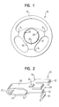
- FIG. 1 shows a vehicle steering wheel 10 with a steering wheel rim 12, spokes 14 and a centrally arranged gas bag module 16.
- the gas bag module 16 is designed as a so-called floating horn gas bag module, i. to actuate the horn, the entire gas bag module in the axial direction of the vehicle steering wheel 10 can be depressed.
- the gas bag module 16 is surrounded by a diaphragm 18 which is immovably fixed to the vehicle steering wheel 10.
- special elastic positioning elements 22 for positioning and guiding the airbag module 16 are provided relative to the immovable components of the vehicle steering wheel 10, in particular to the adjacent aperture 18.
- the positioning elements 22 are arranged at substantially the same angular distance from one another on the outer circumference of the gas bag module 16.
- FIG. 2 shows a single positioning element 22.
- the positioning element 22 is a spring element and has a support section 24 with a U-shaped profile. At the upper leg 26 of the U-shaped profile, a locking portion 28 connects with an angled tongue 30 at.
- the positioning element 22 also has first abutment sections 32 and opposite second abutment sections 34 and an upwardly bent nose 36.
- the vehicle steering wheel 10 is shown in the mounted state, in which the diaphragm 18 and the cap 38 of the airbag module 16 are opposite.
- the gas bag module 16 is attached to the vehicle steering wheel 10, that in case of activation of the gas bag module 16, the firing forces on this primary connection to the vehicle steering wheel 10 are transmitted.
- the positioning elements 22 serve the spatial positioning and guidance of the gas bag module 16.
- the positioning elements 22 are arranged so that the support portion 24 is received in a section of the aperture 18 and is supported on a support 40.
- the nose 36 engages in a matching section of the aperture 18, while the first abutment portions 32 are supported on a side wall 42 of the cap 38 and the second abutment portions 34 on the diaphragm 18. In this way, a frictional fixation of the gas bag module 16 is provided in a direction perpendicular to the steering wheel axis level.
- the locking portion 28 of the positioning member 22 with the angled tongue 30 and the contour 44 of the side wall 42 of the cap 38 are coordinated so that the cap 38 by axial insertion with the positioning member 22 is locked (secondary latching).
- the positive or non-positive axial fixation by the Sekundärverrastung is designed so that a repeated installation and removal of the cap 38 is possible.
- the free tongue 30 of the locking portion 28 is biased in the assembled state, i. it exerts a force on the cap 38 and thus on the gas bag module 16 having a component in the axial direction and a component in a direction perpendicular thereto.
- the positioning element 22 moves with practically no friction.
- the abutment sections 32, 34 and the latching section 28 sörgen for a guide and an actuation or restoring force to oppose the movement of the airbag module 16 a certain resistance and to move the airbag module 16 back to the starting position.
- the triggering of the horn can be done with the aid of a horn contact element 48, which is arranged on the lower leg 46 of the positioning element 22, on the carrier 40 or on another component below the aperture 18, as shown in dashed lines in Figure 3.
- a horn contact element 48 which is arranged on the lower leg 46 of the positioning element 22, on the carrier 40 or on another component below the aperture 18, as shown in dashed lines in Figure 3.
- the positioning elements 22 thus fulfill a plurality of functions: The non-positive spatial fixation of the airbag module 16, the bias of the airbag module 16 to prevent vibration, the leadership of the airbag module 16 in horn operation and the determination of the actuation force and the provision of the restoring force in horn operation.
Landscapes
- Engineering & Computer Science (AREA)
- Mechanical Engineering (AREA)
- Air Bags (AREA)
Abstract
Description
- Die Erfindung betrifft ein Fahrzeuglenkrad mit einem Gassackmodul und einem dem Gassackmodul benachbarten, unbeweglich befestigten Bauteil, insbesondere einer Blende.
- Die Befestigung eines Gassackmoduls an einem Fahrzeuglenkrad ist aufgrund der hohen Anforderungen an die Positionierung des Gassackmoduls mit Schwierigkeiten verbunden. Eine ungenaue Positionierung des Gassackmoduls hat nicht nur unterschiedliche Spaltmaße zur Folge, sondern kann auch zu unerwünschten Geräuschen durch Lagerreibung oder Anschlagen des Gassackmoduls führen. Außerdem führt die Addition der Fertigungstoleranzen der beteiligten Bauteile (Toleranzkette) zu schwer beherrschbaren Spalten und Überständen. Dies betrifft besonders sogenannte Floating-Horn-Gassackmodule, die gegenüber benachbarten Bauteilen des Fahrzeuglenkrads beweglich sind. Bisher bekannte Lösungen zur Positionierung solcher Gassackmodule sind meist aufwendig und großbauend.
- Die Erfindung schafft ein Fahrzeuglenkrad, bei dem das Gassackmodul leicht montierbar ist und automatisch richtig positioniert wird.
- Gemäß der Erfindung ist hierzu bei einem Fahrzeuglenkrad der eingangs genannten Art wenigstens ein separates elastisches Positionierelement vorgesehen, das die Lage des Gassackmoduls relativ zu dem benachbarten Bauteil festlegt. Das elastische Positionierelement drückt das Gassackmodul ohne weiteres Zutun in die gewünschte Position, so daß auch bei Floating-Horn-Gassackmodulen nach jeder Hupenbetätigung immer wieder eine korrekte Position erreicht wird. Somit bilden die klein ausführbaren Positionierelemente eine geräuschlose Führung für das Gassackmodul, das kleine, beherrschbare Spalte und Überstände ermöglicht. Die Positionierelemente sind austauschbar und können für unterschiedliche Anforderungen ausgelegt werden.
- Das Positionierelement kann in vorteilhafter Weise für die Herstellung eines Hupenkontakts zur Hupenauslösung genutzt werden, indem das Positionierelement auf ein Hupenkontaktelement einwirkt.
- Gemäß einer bevorzugten Ausführungsform der Erfindung ist das Positionierelement ein Federelement mit einem Abstützabschnitt und einem Rastabschnitt, wobei der Abstützabschnitt ein U-förmiges Profil mit zwei Schenkeln aufweist und der Rastabschnitt mit einem der Schenkel verbunden ist. Bei dieser Ausgestaltung des Positionierelements kann gemäß einer günstigen Anordnung der Rastabschnitt am Gassackmodul angreifen und der Abstützabschnitt zwischen dem benachbarten Bauteil und einem Träger angeordnet sein.
- Das Positionierelement ist vorzugsweise so ausgelegt, daß es eine Vorspannkraft auf das Gassackmodul in axialer Richtung des Fahrzeuglenkrads und/oder in einer zur axialen Richtung des Fahrzeuglenkrads senkrechten Richtung ausübt, so daß mit dem erfindungsgemäßen Positionierelement neben der räumlichen Positionierung auch für eine Betätigungskraft und eine Rückstellkraft bei der Hupenbetätigung gesorgt ist und Vibrationen des Gassackmoduls vermieden werden.
- Vorzugsweise stellt die Positionierung des Gassackmoduls durch das erfindungsgemäße Positionierelement eine Ergänzung zu einem vom Positionierelement unabhängigen primären Befestigungsmechanismus dar.
- Eine korrekte Positionierung des Gassackmoduls in allen zur Lenkradachse senkrechten Richtungen läßt sich am einfachsten durch wenigstens drei über den Umfang des Gassackmoduls verteilte Positionierelemente erreichen.
- Weitere Merkmale und Vorteile der Erfindung ergeben sich aus der nachfolgenden Beschreibung eines Ausführungsbeispiels und aus den beigefügten Zeichnungen, auf die Bezug genommen wird. In den Zeichnungen zeigen:
- Figur 1 eine Draufsicht auf ein erfindungsgemäßes Fahrzeuglenkrad;
- Figur 2 eine perspektivische Ansicht eines Positionierelements; und
- Figur 3 einen Schnitt durch einen Teil des Fahrzeuglenkrads aus Figur 1.
- In Figur 1 ist ein Fahrzeuglenkrad 10 mit einem Lenkradkranz 12, Speichen 14 und einem zentral angeordneten Gassackmodul 16 dargestellt. Das Gassackmodul 16 ist als sogenanntes Floating-Horn-Gassackmodul ausgebildet, d.h. zur Betätigung der Hupe kann das gesamte Gassackmodul in axialer Richtung des Fahrzeuglenkrads 10 niedergedrückt werden. Das Gassackmodul 16 ist von einer Blende 18 umgeben, die unbeweglich am Fahrzeuglenkrad 10 befestigt ist.
- An drei Stellen 20 sind spezielle elastische Positionierelemente 22 zur Positionierung und Führung des Gassackmoduls 16 relativ zu den unbeweglichen Bauteilen des Fahrzeuglenkrads 10, insbesondere zur benachbarten Blende 18, vorgesehen. Die Positionierelemente 22 sind im wesentlichen im gleichen Winkelabstand voneinander am Außenumfang des Gassackmoduls 16 angeordnet.
- Figur 2 zeigt ein einzelnes Positionierelement 22. Das Positionierelement 22 ist ein Federelement und weist einen Abstützabschnitt 24 mit U-förmigem Profil auf. An den oberen Schenkel 26 des U-förmigen Profils schließt sich ein Rastabschnitt 28 mit einer abgewinkelten Zunge 30 an. Das Positionierelement 22 weist ferner erste Anlageabschnitte 32 und entgegengesetzte zweite Anlageabschnitte 34 sowie eine nach oben gebogene Nase 36 auf.
- In Figur 3 ist das Fahrzeuglenkrad 10 im montierten Zustand dargestellt, in dem sich die Blende 18 und die Abdeckkappe 38 des Gassackmoduls 16 gegenüberliegen. Mittels eines von den Positionierelementen 22 unabhängigen primären Befestigungsmechanismus (nicht gezeigt), insbesondere eines Rastmechanismus, ist das Gassackmodul 16 so am Fahrzeuglenkrad 10 befestigt, daß im Falle einer Aktivierung des Gassackmoduls 16 die Schußkräfte über diese primäre Anbindung auf das Fahrzeuglenkrad 10 übertragen werden. Die Positionierelemente 22 dienen dagegen der räumlichen Positionierung und Führung des Gassackmoduls 16.
- Wie in Figur 3 gezeigt, sind die Positionierelemente 22 so angeordnet, daß der Abstützabschnitt 24 in einem Ausschnitt der Blende 18 aufgenommen ist und sich auf einem Träger 40 abstützt. Die Nase 36 greift in einen passenden Ausschnitt der Blende 18, während sich die ersten Anlageabschnitte 32 an einer Seitenwand 42 der Abdeckkappe 38 und die zweiten Anlageabschnitte 34 an der Blende 18 abstützen. Auf diese Weise ist für eine kraftschlüssige Fixierung des Gassackmoduls 16 in einer zur Lenkradachse senkrechten Ebene gesorgt.
- Der Rastabschnitt 28 des Positionierelements 22 mit der abgewinkelten Zunge 30 und die Kontur 44 der Seitenwand 42 der Abdeckkappe 38 sind so aufeinander abgestimmt, daß die Abdeckkappe 38 durch axiales Einschieben mit dem Positionierelement 22 verrastet (Sekundärverrastung). Die form- bzw. kraftschlüssige axiale Fixierung durch die Sekundärverrastung ist so ausgelegt, daß ein wiederholter Ein- und Ausbau der Abdeckkappe 38 möglich ist. Die freie Zunge 30 des Rastabschnitts 28 ist im montierten Zustand vorgespannt, d.h. sie übt eine Kraft auf die Abdeckkappe 38 und damit auf das Gassackmodul 16 aus, die eine Komponente in axialer Richtung und eine Komponente in einer dazu senkrechten Richtung aufweist.
- Bei Verwendung mehrerer Positionierelemente 22 ergibt sich dadurch insgesamt eine definierte Positionierung des Gassackmoduls 16 relativ zur benachbarten Blende 18 unter einer Vorspannung, die Vibrationen des beweglichen Gassackmoduls entgegenwirkt. Auf ansonsten übliche Druckfedern oder dergleichen zur Vibrationsdämpfung kann somit verzichtet werden.
- Wird das Gassackmodul 16 zur Hupenbetätigung in axialer Richtung niedergedrückt, bewegt sich das Positionierelement 22 mit Ausnahme des unteren Schenkels 46 praktisch ohne Reibung mit. Die Anlageabschnitte 32, 34 und der Rastabschnitt 28 sörgen für eine Führung und eine Betätigungs- bzw. Rückstellkraft, um der Bewegung des Gassackmoduls 16 einen gewissen Widerstand entgegenzusetzen und um das Gassackmodul 16 wieder zurück in die Ausgangsstellung zu bewegen.
- Die Auslösung der Hupe kann mit Hilfe eines Hupenkontaktelements 48 erfolgen, das auf dem unteren Schenkel 46 des Positionierelements 22, auf dem Träger 40 oder auf einem anderen Bauteil unterhalb der Blende 18 angeordnet ist, wie in Figur 3 gestrichelt dargestellt. Durch das Niederdrücken des Gassackmoduls 16 wird der obere Schenkel 26 des Positionierelements 22 auf das Hupenkontaktelement 48 bewegt und stellt dadurch einen elektrischen Kontakt zur Auslösung der Hupe her.
- Die Positionierelemente 22 erfüllen somit mehrere Funktionen: Die kraftschlüssige räumliche Fixierung des Gassackmoduls 16, die Vorspannung des Gassackmoduls 16 zur Vibrationsvermeidung, die Führung des Gassackmoduls 16 bei Hupenbetätigung sowie die Festlegung der Betätigungskraft und die Bereitstellung der Rückstellungskraft bei Hupenbetätigung.
Claims (11)
- Fahrzeuglenkrad mit einem Gassackmodul (16) und einem dem Gassackmodul (16) benachbarten, unbeweglich befestigten Bauteil (18), insbesondere einer Blende, gekennzeichnet durch wenigstens ein separates elastisches Positionierelement (22), das die Lage des Gassackmoduls (16) relativ zu dem benachbarten Bauteil festlegt.
- Fahrzeuglenkrad nach Anspruch 1, dadurch gekennzeichnet, daß das Gassackmodul (16) ein Floating-Horn-Gassackmodul ist.
- Fahrzeuglenkrad nach Anspruch 1 oder 2, dadurch gekennzeichnet, daß das Positionierelement auf ein Hupenkontaktelement einwirkt.
- Fahrzeuglenkrad nach einem der vorhergehenden Ansprüche, dadurch gekennzeichnet, daß das Positionierelement (22) ein Federelement mit einem Abstützabschnitt (24) und einem Rastabschnitt (28) ist, wobei der Abstützabschnitt (24) ein U-förmiges Profil mit zwei Schenkeln (26, 46) aufweist und der Rastabschnitt (28) mit einem der Schenkel (26) verbunden ist.
- Fahrzeuglenkrad nach Anspruch 4, dadurch gekennzeichnet, daß der Rastabschnitt (28) am Gassackmodul (16) angreift und der Abstützabschnitt (24) zwischen dem benachbarten Bauteil (18) und einem Träger (40) angeordnet ist.
- Fahrzeuglenkrad nach einem der vorhergehenden Ansprüche, dadurch gekennzeichnet, daß das Positionierelement (22) erste Anlageabschnitte (32) aufweist, über die sich das Positionierelement (22) am Gassackmodul (16) abstützt.
- Fahrzeuglenkrad nach einem der vorhergehenden Ansprüche, dadurch gekennzeichnet, daß das Positionierelement (22) zweite Anlageabschnitte (34) aufweist, über die sich das Positionierelement (22) am benachbarten Bauteil (18) abstützt.
- Fahrzeuglenkrad nach einem der vorhergehenden Ansprüche, dadurch gekennzeichnet, daß das Positionierelement (22) so ausgelegt ist, daß es eine Vorspannkraft auf das Gassackmodul (16) in axialer Richtung des Fahrzeuglenkrads (10) ausübt.
- Fahrzeuglenkrad nach einem der vorhergehenden Ansprüche, dadurch gekennzeichnet, daß das Positionierelement (22) so ausgelegt ist, daß es eine Vorspannkraft auf das Gassackmodul (16) in einer zur axialen Richtung des Fahrzeuglenkrads (10) senkrechten Richtung ausübt.
- Fahrzeuglenkrad nach einem der vorhergehenden Ansprüche, dadurch gekennzeichnet, daß das Gassackmodul (16) über einen vom Positionierelement (22) unabhängigen primären Befestigungsmechanismus am Fahrzeuglenkrad (10) angebracht ist.
- Fahrzeuglenkrad nach einem der vorhergehenden Ansprüche, dadurch gekennzeichnet, daß wenigstens drei über den Umfang des Gassackmoduls (16) verteilte Positionierelemente (22) vorgesehen sind.
Applications Claiming Priority (1)
| Application Number | Priority Date | Filing Date | Title |
|---|---|---|---|
| DE202005013383U DE202005013383U1 (de) | 2005-08-24 | 2005-08-24 | Fahrzeuglenkrad mit Gassackmodul |
Publications (2)
| Publication Number | Publication Date |
|---|---|
| EP1757491A1 true EP1757491A1 (de) | 2007-02-28 |
| EP1757491B1 EP1757491B1 (de) | 2008-05-07 |
Family
ID=35853920
Family Applications (1)
| Application Number | Title | Priority Date | Filing Date |
|---|---|---|---|
| EP06017342A Ceased EP1757491B1 (de) | 2005-08-24 | 2006-08-21 | Fahrzeuglenkrad mit Gassackmodul |
Country Status (3)
| Country | Link |
|---|---|
| US (1) | US7784825B2 (de) |
| EP (1) | EP1757491B1 (de) |
| DE (2) | DE202005013383U1 (de) |
Families Citing this family (10)
| Publication number | Priority date | Publication date | Assignee | Title |
|---|---|---|---|---|
| US7922194B2 (en) * | 2006-11-13 | 2011-04-12 | Autoliv Development Ab | Air-bag cover arrangement |
| US7891702B2 (en) * | 2008-03-27 | 2011-02-22 | Intertec Systems, Llc | Apparatus and method for attaching passenger side inflatable restraint chute |
| US7766372B2 (en) * | 2008-06-11 | 2010-08-03 | Gm Global Technology Operations, Inc. | Vehicle instrument panel with nonvisible airbag tear seam and deployment door and method of making the same |
| EP2907700B1 (de) * | 2014-02-17 | 2021-07-21 | Dalphi Metal España, S.A. | Hupensystem |
| CN103921752B (zh) * | 2014-04-02 | 2016-09-28 | 延锋百利得(上海)汽车安全系统有限公司 | 一种设有安全气囊模块定位装置的方向盘 |
| DE102015010099B4 (de) * | 2015-08-05 | 2025-03-27 | Autoliv Development Ab | Lenkradeinheit |
| US9707927B1 (en) * | 2016-03-03 | 2017-07-18 | Autoliv Asp, Inc. | Seatbelt buckle apparatuses including switch wire harnesses and strain relief thereof |
| KR102335527B1 (ko) * | 2017-06-27 | 2021-12-03 | 현대자동차주식회사 | 자동차용 혼 작동 장치 |
| DE102020115031A1 (de) | 2020-06-05 | 2021-12-09 | Autoliv Development Ab | Lenkrad, welches ein Gassackmodul aufweist |
| KR20240033489A (ko) * | 2022-09-05 | 2024-03-12 | 현대자동차주식회사 | 스티어링휠과, 그 스티어링휠의 댐퍼유닛 |
Citations (4)
| Publication number | Priority date | Publication date | Assignee | Title |
|---|---|---|---|---|
| US5755458A (en) * | 1996-12-11 | 1998-05-26 | Textron Inc. | Slide-in and snap-fit air bag mounting arrangement |
| GB2390337A (en) * | 2002-07-02 | 2004-01-07 | Autoliv Dev | Steering wheel with airbag centrally and resiliently mounted |
| DE20316519U1 (de) * | 2003-10-27 | 2004-03-04 | Trw Automotive Safety Systems Gmbh | Gassackrückhaltesystem |
| US20040217580A1 (en) * | 2003-04-29 | 2004-11-04 | Schorle Michael A. | Method and apparatus for coupling a driver's side airbag to a steering wheel |
Family Cites Families (12)
| Publication number | Priority date | Publication date | Assignee | Title |
|---|---|---|---|---|
| JPH08207783A (ja) * | 1994-12-07 | 1996-08-13 | Toyoda Gosei Co Ltd | ステアリングホイール |
| DE19732022B4 (de) * | 1996-07-29 | 2004-02-12 | Autoliv Development Ab | Gassackeinrichtung mit integriertem Hupenschalter |
| DE69725246T2 (de) * | 1996-08-06 | 2004-07-29 | Toyoda Gosei Co., Ltd., Haruhi | Lenkrad |
| GB9616852D0 (en) | 1996-08-10 | 1996-09-25 | United Technologies Automotive | Steering wheel assembly |
| US6626459B2 (en) * | 2000-03-31 | 2003-09-30 | Toyoda Gosei Co., Ltd. | Air bag for steering wheel |
| JP2002012115A (ja) | 2000-06-28 | 2002-01-15 | Nippon Plast Co Ltd | エアバッグ装置 |
| JP2002120730A (ja) * | 2000-10-19 | 2002-04-23 | Tokai Rika Co Ltd | ステアリングスイッチの取付構造 |
| US6830263B2 (en) * | 2002-02-08 | 2004-12-14 | Key Safety Systems, Inc. | Method for attaching an airbag module |
| KR100468540B1 (ko) * | 2002-12-04 | 2005-01-27 | 현대모비스 주식회사 | 스티어링휠의 에어백모듈 설치구조 |
| US7159898B2 (en) * | 2004-04-20 | 2007-01-09 | General Motors Corporation | Vehicle air bag module retention system |
| DE602004014253D1 (de) * | 2004-05-10 | 2008-07-17 | Key Safety Systems Inc | Baugruppe mit einem Lenkrad und einem Gassackmodul |
| JP4797584B2 (ja) * | 2005-03-16 | 2011-10-19 | タカタ株式会社 | エアバッグ装置付きステアリングホイール |
-
2005
- 2005-08-24 DE DE202005013383U patent/DE202005013383U1/de not_active Expired - Lifetime
-
2006
- 2006-08-16 US US11/505,084 patent/US7784825B2/en not_active Expired - Fee Related
- 2006-08-21 EP EP06017342A patent/EP1757491B1/de not_active Ceased
- 2006-08-21 DE DE502006000743T patent/DE502006000743D1/de active Active
Patent Citations (4)
| Publication number | Priority date | Publication date | Assignee | Title |
|---|---|---|---|---|
| US5755458A (en) * | 1996-12-11 | 1998-05-26 | Textron Inc. | Slide-in and snap-fit air bag mounting arrangement |
| GB2390337A (en) * | 2002-07-02 | 2004-01-07 | Autoliv Dev | Steering wheel with airbag centrally and resiliently mounted |
| US20040217580A1 (en) * | 2003-04-29 | 2004-11-04 | Schorle Michael A. | Method and apparatus for coupling a driver's side airbag to a steering wheel |
| DE20316519U1 (de) * | 2003-10-27 | 2004-03-04 | Trw Automotive Safety Systems Gmbh | Gassackrückhaltesystem |
Also Published As
| Publication number | Publication date |
|---|---|
| EP1757491B1 (de) | 2008-05-07 |
| DE502006000743D1 (de) | 2008-06-19 |
| DE202005013383U1 (de) | 2006-02-09 |
| US7784825B2 (en) | 2010-08-31 |
| US20070045996A1 (en) | 2007-03-01 |
Similar Documents
| Publication | Publication Date | Title |
|---|---|---|
| EP2703237A1 (de) | Baugruppe mit einem Regensensor und einer Halteklammer für den Regensensor | |
| DE3424771A1 (de) | Tastenfeld | |
| EP1398227A1 (de) | Airbagmodul sowie Baugruppe aus einem Lenkrad und einem Airbagmodul | |
| DE202006021160U1 (de) | Verstellbare Lenksäule für ein Kraftfahrzeug | |
| EP3116751B1 (de) | Verbinderbauteil zur befestigung eines gassackmoduls an einem lenkrad, set mit einem solchen verbinderbauteil und einer positionierhülse sowie lenkrad, gassackmodul, lenkradbaugruppe und herstellungsverfahren hierfür | |
| EP1757491B1 (de) | Fahrzeuglenkrad mit Gassackmodul | |
| DE2210114A1 (de) | Schalteranordnung | |
| EP2184754B1 (de) | Schalter | |
| DE3043658A1 (de) | Vakuumschalter | |
| WO2022184535A1 (de) | Lasttragender gurtaufroller | |
| EP1764813B1 (de) | Elektrischer Schalter | |
| DE19823894C1 (de) | Schnappscheibenschalter mit Befestigungselement | |
| DE10157440A1 (de) | Rasteinrichtung für ein Airbagmodul | |
| EP1088737A2 (de) | Baugruppe mit Vorrichtung zum Ausrichten von zwei benachbarten Teilen | |
| WO2004048150A1 (de) | Anordnung zur hupenbetätigung an lenkrädern | |
| EP1281586B1 (de) | Lenkrad mit beweglichem Gassackmodul | |
| EP1053135A1 (de) | Lenkrad mit eingestecktem airbagmodul | |
| DE102022122056B3 (de) | Lenkrad mit einem Airbagmodul | |
| DE102021110731B3 (de) | Airbag-Anordnung | |
| EP3891017A1 (de) | Hupeinrichtung für ein lenkrad, lenkrad mit einer derartigen hupeinrichtung sowie herstellungsverfahren | |
| DE19501855C2 (de) | Verfahren zur Herstellung einer mehrere funktional eigenständige elektrische Schalter aufweisenden Schalteranordnung | |
| DE102018104728A1 (de) | Hupensystem für ein Fahrzeug | |
| EP1475279A2 (de) | Baugruppe zur Befestigung eines Gassackmoduls | |
| EP1527961A1 (de) | Gassackrückhaltesystem | |
| DE102008025378A1 (de) | Befestigungsanordnung zur Gurtführung eines Sicherheitsgurtes in einem Kraftfahrzeug, sowie Verfahren zur Montage einer solchen Befestigungsanordnung |
Legal Events
| Date | Code | Title | Description |
|---|---|---|---|
| PUAI | Public reference made under article 153(3) epc to a published international application that has entered the european phase |
Free format text: ORIGINAL CODE: 0009012 |
|
| AK | Designated contracting states |
Kind code of ref document: A1 Designated state(s): AT BE BG CH CY CZ DE DK EE ES FI FR GB GR HU IE IS IT LI LT LU LV MC NL PL PT RO SE SI SK TR |
|
| AX | Request for extension of the european patent |
Extension state: AL BA HR MK YU |
|
| 17P | Request for examination filed |
Effective date: 20070827 |
|
| AKX | Designation fees paid |
Designated state(s): DE FR |
|
| GRAP | Despatch of communication of intention to grant a patent |
Free format text: ORIGINAL CODE: EPIDOSNIGR1 |
|
| GRAS | Grant fee paid |
Free format text: ORIGINAL CODE: EPIDOSNIGR3 |
|
| GRAA | (expected) grant |
Free format text: ORIGINAL CODE: 0009210 |
|
| AK | Designated contracting states |
Kind code of ref document: B1 Designated state(s): DE FR |
|
| REF | Corresponds to: |
Ref document number: 502006000743 Country of ref document: DE Date of ref document: 20080619 Kind code of ref document: P |
|
| PLBE | No opposition filed within time limit |
Free format text: ORIGINAL CODE: 0009261 |
|
| STAA | Information on the status of an ep patent application or granted ep patent |
Free format text: STATUS: NO OPPOSITION FILED WITHIN TIME LIMIT |
|
| 26N | No opposition filed |
Effective date: 20090210 |
|
| REG | Reference to a national code |
Ref country code: FR Ref legal event code: PLFP Year of fee payment: 11 |
|
| REG | Reference to a national code |
Ref country code: FR Ref legal event code: PLFP Year of fee payment: 12 |
|
| REG | Reference to a national code |
Ref country code: FR Ref legal event code: PLFP Year of fee payment: 13 |
|
| PGFP | Annual fee paid to national office [announced via postgrant information from national office to epo] |
Ref country code: DE Payment date: 20190831 Year of fee payment: 14 Ref country code: FR Payment date: 20190826 Year of fee payment: 14 |
|
| REG | Reference to a national code |
Ref country code: DE Ref legal event code: R119 Ref document number: 502006000743 Country of ref document: DE |
|
| PG25 | Lapsed in a contracting state [announced via postgrant information from national office to epo] |
Ref country code: FR Free format text: LAPSE BECAUSE OF NON-PAYMENT OF DUE FEES Effective date: 20200831 Ref country code: DE Free format text: LAPSE BECAUSE OF NON-PAYMENT OF DUE FEES Effective date: 20210302 |