EP1756831B1 - Internally replenished enclosure - Google Patents
Internally replenished enclosure Download PDFInfo
- Publication number
- EP1756831B1 EP1756831B1 EP05752082A EP05752082A EP1756831B1 EP 1756831 B1 EP1756831 B1 EP 1756831B1 EP 05752082 A EP05752082 A EP 05752082A EP 05752082 A EP05752082 A EP 05752082A EP 1756831 B1 EP1756831 B1 EP 1756831B1
- Authority
- EP
- European Patent Office
- Prior art keywords
- enclosure
- gas
- bubbles
- gas source
- resin
- Prior art date
- Legal status (The legal status is an assumption and is not a legal conclusion. Google has not performed a legal analysis and makes no representation as to the accuracy of the status listed.)
- Expired - Lifetime
Links
- 238000000034 method Methods 0.000 claims abstract description 13
- 239000007789 gas Substances 0.000 claims description 131
- 239000012528 membrane Substances 0.000 claims description 35
- 229920005989 resin Polymers 0.000 claims description 29
- 239000011347 resin Substances 0.000 claims description 29
- 239000011521 glass Substances 0.000 claims description 18
- 239000011261 inert gas Substances 0.000 claims description 11
- 229910052751 metal Inorganic materials 0.000 claims description 11
- 239000002184 metal Substances 0.000 claims description 11
- 238000009826 distribution Methods 0.000 claims description 9
- 229910044991 metal oxide Inorganic materials 0.000 claims description 8
- 150000004706 metal oxides Chemical class 0.000 claims description 8
- 239000000919 ceramic Substances 0.000 claims description 4
- 238000004026 adhesive bonding Methods 0.000 claims 1
- 239000001307 helium Substances 0.000 description 20
- 229910052734 helium Inorganic materials 0.000 description 20
- SWQJXJOGLNCZEY-UHFFFAOYSA-N helium atom Chemical compound [He] SWQJXJOGLNCZEY-UHFFFAOYSA-N 0.000 description 20
- 239000000463 material Substances 0.000 description 13
- PEDCQBHIVMGVHV-UHFFFAOYSA-N Glycerine Chemical compound OCC(O)CO PEDCQBHIVMGVHV-UHFFFAOYSA-N 0.000 description 9
- 230000035699 permeability Effects 0.000 description 9
- 239000000853 adhesive Substances 0.000 description 8
- 230000001070 adhesive effect Effects 0.000 description 8
- 229910052782 aluminium Inorganic materials 0.000 description 8
- XAGFODPZIPBFFR-UHFFFAOYSA-N aluminium Chemical compound [Al] XAGFODPZIPBFFR-UHFFFAOYSA-N 0.000 description 8
- 238000004817 gas chromatography Methods 0.000 description 8
- 238000000576 coating method Methods 0.000 description 7
- XKRFYHLGVUSROY-UHFFFAOYSA-N Argon Chemical compound [Ar] XKRFYHLGVUSROY-UHFFFAOYSA-N 0.000 description 4
- CURLTUGMZLYLDI-UHFFFAOYSA-N Carbon dioxide Chemical compound O=C=O CURLTUGMZLYLDI-UHFFFAOYSA-N 0.000 description 4
- VYPSYNLAJGMNEJ-UHFFFAOYSA-N Silicium dioxide Chemical compound O=[Si]=O VYPSYNLAJGMNEJ-UHFFFAOYSA-N 0.000 description 4
- 239000003570 air Substances 0.000 description 4
- 239000012298 atmosphere Substances 0.000 description 4
- 239000011248 coating agent Substances 0.000 description 4
- 230000007423 decrease Effects 0.000 description 4
- 238000009792 diffusion process Methods 0.000 description 4
- -1 for example Substances 0.000 description 4
- 239000004593 Epoxy Substances 0.000 description 3
- 238000006243 chemical reaction Methods 0.000 description 3
- 150000002739 metals Chemical class 0.000 description 3
- 239000000203 mixture Substances 0.000 description 3
- KDLHZDBZIXYQEI-UHFFFAOYSA-N palladium Substances [Pd] KDLHZDBZIXYQEI-UHFFFAOYSA-N 0.000 description 3
- 239000002245 particle Substances 0.000 description 3
- 230000002829 reductive effect Effects 0.000 description 3
- 238000004544 sputter deposition Methods 0.000 description 3
- 238000003860 storage Methods 0.000 description 3
- 238000012360 testing method Methods 0.000 description 3
- QGZKDVFQNNGYKY-UHFFFAOYSA-N Ammonia Chemical compound N QGZKDVFQNNGYKY-UHFFFAOYSA-N 0.000 description 2
- IJGRMHOSHXDMSA-UHFFFAOYSA-N Atomic nitrogen Chemical compound N#N IJGRMHOSHXDMSA-UHFFFAOYSA-N 0.000 description 2
- PXHVJJICTQNCMI-UHFFFAOYSA-N Nickel Chemical compound [Ni] PXHVJJICTQNCMI-UHFFFAOYSA-N 0.000 description 2
- 229910045601 alloy Inorganic materials 0.000 description 2
- 239000000956 alloy Substances 0.000 description 2
- 229910052786 argon Inorganic materials 0.000 description 2
- QVGXLLKOCUKJST-UHFFFAOYSA-N atomic oxygen Chemical compound [O] QVGXLLKOCUKJST-UHFFFAOYSA-N 0.000 description 2
- 229910002092 carbon dioxide Inorganic materials 0.000 description 2
- 239000001569 carbon dioxide Substances 0.000 description 2
- 238000005516 engineering process Methods 0.000 description 2
- 239000010408 film Substances 0.000 description 2
- 229910052739 hydrogen Inorganic materials 0.000 description 2
- 239000001257 hydrogen Substances 0.000 description 2
- 229910010272 inorganic material Inorganic materials 0.000 description 2
- 239000011147 inorganic material Substances 0.000 description 2
- 239000004816 latex Substances 0.000 description 2
- 229920000126 latex Polymers 0.000 description 2
- 230000001590 oxidative effect Effects 0.000 description 2
- TWNQGVIAIRXVLR-UHFFFAOYSA-N oxo(oxoalumanyloxy)alumane Chemical compound O=[Al]O[Al]=O TWNQGVIAIRXVLR-UHFFFAOYSA-N 0.000 description 2
- 229910052760 oxygen Inorganic materials 0.000 description 2
- 239000001301 oxygen Substances 0.000 description 2
- 229910052763 palladium Inorganic materials 0.000 description 2
- BASFCYQUMIYNBI-UHFFFAOYSA-N platinum Chemical compound [Pt] BASFCYQUMIYNBI-UHFFFAOYSA-N 0.000 description 2
- 238000005070 sampling Methods 0.000 description 2
- 239000000377 silicon dioxide Substances 0.000 description 2
- 239000000243 solution Substances 0.000 description 2
- 229910052719 titanium Inorganic materials 0.000 description 2
- 239000010936 titanium Substances 0.000 description 2
- OKTJSMMVPCPJKN-UHFFFAOYSA-N Carbon Chemical compound [C] OKTJSMMVPCPJKN-UHFFFAOYSA-N 0.000 description 1
- UGFAIRIUMAVXCW-UHFFFAOYSA-N Carbon monoxide Chemical compound [O+]#[C-] UGFAIRIUMAVXCW-UHFFFAOYSA-N 0.000 description 1
- VYZAMTAEIAYCRO-UHFFFAOYSA-N Chromium Chemical compound [Cr] VYZAMTAEIAYCRO-UHFFFAOYSA-N 0.000 description 1
- RYGMFSIKBFXOCR-UHFFFAOYSA-N Copper Chemical compound [Cu] RYGMFSIKBFXOCR-UHFFFAOYSA-N 0.000 description 1
- 229920000219 Ethylene vinyl alcohol Polymers 0.000 description 1
- UFHFLCQGNIYNRP-UHFFFAOYSA-N Hydrogen Chemical compound [H][H] UFHFLCQGNIYNRP-UHFFFAOYSA-N 0.000 description 1
- KKCBUQHMOMHUOY-UHFFFAOYSA-N Na2O Inorganic materials [O-2].[Na+].[Na+] KKCBUQHMOMHUOY-UHFFFAOYSA-N 0.000 description 1
- 239000004698 Polyethylene Substances 0.000 description 1
- BLRPTPMANUNPDV-UHFFFAOYSA-N Silane Chemical compound [SiH4] BLRPTPMANUNPDV-UHFFFAOYSA-N 0.000 description 1
- BQCADISMDOOEFD-UHFFFAOYSA-N Silver Chemical compound [Ag] BQCADISMDOOEFD-UHFFFAOYSA-N 0.000 description 1
- ATJFFYVFTNAWJD-UHFFFAOYSA-N Tin Chemical compound [Sn] ATJFFYVFTNAWJD-UHFFFAOYSA-N 0.000 description 1
- RTAQQCXQSZGOHL-UHFFFAOYSA-N Titanium Chemical compound [Ti] RTAQQCXQSZGOHL-UHFFFAOYSA-N 0.000 description 1
- NRTOMJZYCJJWKI-UHFFFAOYSA-N Titanium nitride Chemical compound [Ti]#N NRTOMJZYCJJWKI-UHFFFAOYSA-N 0.000 description 1
- HCHKCACWOHOZIP-UHFFFAOYSA-N Zinc Chemical compound [Zn] HCHKCACWOHOZIP-UHFFFAOYSA-N 0.000 description 1
- QCWXUUIWCKQGHC-UHFFFAOYSA-N Zirconium Chemical compound [Zr] QCWXUUIWCKQGHC-UHFFFAOYSA-N 0.000 description 1
- PEQYWQJRQVAUAZ-UHFFFAOYSA-L [Cr](=O)(=O)(Cl)Cl.C(C(=C)C)(=O)O Chemical compound [Cr](=O)(=O)(Cl)Cl.C(C(=C)C)(=O)O PEQYWQJRQVAUAZ-UHFFFAOYSA-L 0.000 description 1
- 150000001252 acrylic acid derivatives Chemical class 0.000 description 1
- 150000001336 alkenes Chemical class 0.000 description 1
- 239000012080 ambient air Substances 0.000 description 1
- 229910021529 ammonia Inorganic materials 0.000 description 1
- 125000004429 atom Chemical group 0.000 description 1
- 239000011324 bead Substances 0.000 description 1
- 230000002902 bimodal effect Effects 0.000 description 1
- 229910052799 carbon Inorganic materials 0.000 description 1
- 239000006229 carbon black Substances 0.000 description 1
- 229910002091 carbon monoxide Inorganic materials 0.000 description 1
- 239000012159 carrier gas Substances 0.000 description 1
- 238000000541 cathodic arc deposition Methods 0.000 description 1
- 230000008859 change Effects 0.000 description 1
- 238000012512 characterization method Methods 0.000 description 1
- 238000005229 chemical vapour deposition Methods 0.000 description 1
- 229910052804 chromium Inorganic materials 0.000 description 1
- 239000011651 chromium Substances 0.000 description 1
- 229910052681 coesite Inorganic materials 0.000 description 1
- 229910052802 copper Inorganic materials 0.000 description 1
- 239000010949 copper Substances 0.000 description 1
- 229910052906 cristobalite Inorganic materials 0.000 description 1
- 229920006038 crystalline resin Polymers 0.000 description 1
- 238000001514 detection method Methods 0.000 description 1
- 238000006073 displacement reaction Methods 0.000 description 1
- 239000000975 dye Substances 0.000 description 1
- 238000007772 electroless plating Methods 0.000 description 1
- 125000003700 epoxy group Chemical group 0.000 description 1
- 239000004715 ethylene vinyl alcohol Substances 0.000 description 1
- 239000000835 fiber Substances 0.000 description 1
- 230000004907 flux Effects 0.000 description 1
- 239000004088 foaming agent Substances 0.000 description 1
- 239000002241 glass-ceramic Substances 0.000 description 1
- PCHJSUWPFVWCPO-UHFFFAOYSA-N gold Chemical compound [Au] PCHJSUWPFVWCPO-UHFFFAOYSA-N 0.000 description 1
- 229910052737 gold Inorganic materials 0.000 description 1
- 239000010931 gold Substances 0.000 description 1
- 239000004519 grease Substances 0.000 description 1
- RZXDTJIXPSCHCI-UHFFFAOYSA-N hexa-1,5-diene-2,5-diol Chemical compound OC(=C)CCC(O)=C RZXDTJIXPSCHCI-UHFFFAOYSA-N 0.000 description 1
- 125000004435 hydrogen atom Chemical class [H]* 0.000 description 1
- 238000007654 immersion Methods 0.000 description 1
- 238000002347 injection Methods 0.000 description 1
- 239000007924 injection Substances 0.000 description 1
- 229910052743 krypton Inorganic materials 0.000 description 1
- DNNSSWSSYDEUBZ-UHFFFAOYSA-N krypton atom Chemical compound [Kr] DNNSSWSSYDEUBZ-UHFFFAOYSA-N 0.000 description 1
- 230000007246 mechanism Effects 0.000 description 1
- 150000002734 metacrylic acid derivatives Chemical class 0.000 description 1
- 150000001247 metal acetylides Chemical class 0.000 description 1
- 150000002736 metal compounds Chemical class 0.000 description 1
- 229910052752 metalloid Inorganic materials 0.000 description 1
- 150000002738 metalloids Chemical class 0.000 description 1
- WSFSSNUMVMOOMR-NJFSPNSNSA-N methanone Chemical compound O=[14CH2] WSFSSNUMVMOOMR-NJFSPNSNSA-N 0.000 description 1
- 238000002156 mixing Methods 0.000 description 1
- 239000002808 molecular sieve Substances 0.000 description 1
- 239000010705 motor oil Substances 0.000 description 1
- 229910052754 neon Inorganic materials 0.000 description 1
- GKAOGPIIYCISHV-UHFFFAOYSA-N neon atom Chemical compound [Ne] GKAOGPIIYCISHV-UHFFFAOYSA-N 0.000 description 1
- 229910052759 nickel Inorganic materials 0.000 description 1
- 150000004767 nitrides Chemical class 0.000 description 1
- 229910052757 nitrogen Inorganic materials 0.000 description 1
- 239000003921 oil Substances 0.000 description 1
- 239000011368 organic material Substances 0.000 description 1
- 238000012856 packing Methods 0.000 description 1
- 238000005240 physical vapour deposition Methods 0.000 description 1
- 239000000049 pigment Substances 0.000 description 1
- 239000004033 plastic Substances 0.000 description 1
- 229920003023 plastic Polymers 0.000 description 1
- 239000004014 plasticizer Substances 0.000 description 1
- 229910052697 platinum Inorganic materials 0.000 description 1
- 229920000647 polyepoxide Polymers 0.000 description 1
- 229920000728 polyester Polymers 0.000 description 1
- 229920000573 polyethylene Polymers 0.000 description 1
- 229920006254 polymer film Polymers 0.000 description 1
- 229920001296 polysiloxane Polymers 0.000 description 1
- 230000005855 radiation Effects 0.000 description 1
- 238000005546 reactive sputtering Methods 0.000 description 1
- 239000006254 rheological additive Substances 0.000 description 1
- 238000007789 sealing Methods 0.000 description 1
- 230000035945 sensitivity Effects 0.000 description 1
- 229910000077 silane Inorganic materials 0.000 description 1
- 229910021332 silicide Inorganic materials 0.000 description 1
- 229910052710 silicon Inorganic materials 0.000 description 1
- 239000010703 silicon Substances 0.000 description 1
- 229910052709 silver Inorganic materials 0.000 description 1
- 239000004332 silver Substances 0.000 description 1
- URGAHOPLAPQHLN-UHFFFAOYSA-N sodium aluminosilicate Chemical compound [Na+].[Al+3].[O-][Si]([O-])=O.[O-][Si]([O-])=O URGAHOPLAPQHLN-UHFFFAOYSA-N 0.000 description 1
- 239000007787 solid Substances 0.000 description 1
- 239000002904 solvent Substances 0.000 description 1
- 229910052682 stishovite Inorganic materials 0.000 description 1
- 239000000126 substance Substances 0.000 description 1
- 239000000454 talc Substances 0.000 description 1
- 229910052623 talc Inorganic materials 0.000 description 1
- 238000010998 test method Methods 0.000 description 1
- 229920001169 thermoplastic Polymers 0.000 description 1
- 229920002725 thermoplastic elastomer Polymers 0.000 description 1
- 229920001187 thermosetting polymer Polymers 0.000 description 1
- 239000004416 thermosoftening plastic Substances 0.000 description 1
- 239000010409 thin film Substances 0.000 description 1
- 239000013008 thixotropic agent Substances 0.000 description 1
- 229910052718 tin Inorganic materials 0.000 description 1
- 239000011135 tin Substances 0.000 description 1
- XOLBLPGZBRYERU-UHFFFAOYSA-N tin dioxide Chemical compound O=[Sn]=O XOLBLPGZBRYERU-UHFFFAOYSA-N 0.000 description 1
- 229910001887 tin oxide Inorganic materials 0.000 description 1
- 229910052905 tridymite Inorganic materials 0.000 description 1
- WFKWXMTUELFFGS-UHFFFAOYSA-N tungsten Chemical compound [W] WFKWXMTUELFFGS-UHFFFAOYSA-N 0.000 description 1
- 229910052721 tungsten Inorganic materials 0.000 description 1
- 239000010937 tungsten Substances 0.000 description 1
- 238000005303 weighing Methods 0.000 description 1
- 229910052725 zinc Inorganic materials 0.000 description 1
- 239000011701 zinc Substances 0.000 description 1
- 229910052726 zirconium Inorganic materials 0.000 description 1
Images
Classifications
-
- G—PHYSICS
- G11—INFORMATION STORAGE
- G11B—INFORMATION STORAGE BASED ON RELATIVE MOVEMENT BETWEEN RECORD CARRIER AND TRANSDUCER
- G11B33/00—Constructional parts, details or accessories not provided for in the other groups of this subclass
- G11B33/14—Reducing influence of physical parameters, e.g. temperature change, moisture, dust
- G11B33/1446—Reducing contamination, e.g. by dust, debris
- G11B33/1466—Reducing contamination, e.g. by dust, debris sealing gaskets
-
- G—PHYSICS
- G11—INFORMATION STORAGE
- G11B—INFORMATION STORAGE BASED ON RELATIVE MOVEMENT BETWEEN RECORD CARRIER AND TRANSDUCER
- G11B33/00—Constructional parts, details or accessories not provided for in the other groups of this subclass
- G11B33/12—Disposition of constructional parts in the apparatus, e.g. of power supply, of modules
- G11B33/121—Disposition of constructional parts in the apparatus, e.g. of power supply, of modules the apparatus comprising a single recording/reproducing device
-
- G—PHYSICS
- G11—INFORMATION STORAGE
- G11B—INFORMATION STORAGE BASED ON RELATIVE MOVEMENT BETWEEN RECORD CARRIER AND TRANSDUCER
- G11B33/00—Constructional parts, details or accessories not provided for in the other groups of this subclass
- G11B33/14—Reducing influence of physical parameters, e.g. temperature change, moisture, dust
- G11B33/1406—Reducing the influence of the temperature
- G11B33/1413—Reducing the influence of the temperature by fluid cooling
-
- G—PHYSICS
- G11—INFORMATION STORAGE
- G11B—INFORMATION STORAGE BASED ON RELATIVE MOVEMENT BETWEEN RECORD CARRIER AND TRANSDUCER
- G11B33/00—Constructional parts, details or accessories not provided for in the other groups of this subclass
- G11B33/14—Reducing influence of physical parameters, e.g. temperature change, moisture, dust
- G11B33/1486—Control/regulation of the pressure, e.g. the pressure inside the housing of a drive
Definitions
- the invention pertains to internally replenished gas-containing enclosures and methods of internally replenishing an enclosure.
- the invention is particularly useful in computer hard disk storage devices.
- Gas-containing enclosures may be advantageous in a variety of applications.
- an enclosure is formed by connecting two or more sections using, for example, mechanical fasteners, welds, or adhesives.
- One or more components are placed within the enclosure, and the enclosure is filled with a gas or gases, for example, an inert gas.
- the completed enclosure contains the gas environment and one or more components protected by the enclosure.
- some hard disk drives are protected within an enclosure.
- the enclosure itself is generally located in an air environment, while the interior of the enclosure is filled with an inert gas (for example, helium).
- an inert gas for example, helium
- the helium environment within the hard disk drive enclosure reduces both the energy required to spin the platters and the sensitivity of the head to ambient pressure fly height.
- the helium environment also may allow manufacturers to build drives with a lower fly height, leading to faster data access and retrieval rates.
- the joints where the sections of an enclosure are connected are susceptible to leaks allowing gases within the enclosure to leave and/or ambient gases to enter the enclosure.
- the enclosure may be sealed using, for example, adhesives, gaskets and/or seals to minimize or substantially eliminate the flow of gases between the ambient environment and the interior of the enclosure.
- gases may diffuse through the materials used to seal the enclosure (for example, the adhesives and gaskets). Whether by leaking, diffusion, or some other mechanism, the relative amount of desired gas within the enclosure generally diminishes over time.
- the desired gas environment within the enclosure should be maintained for the life of the components, which may be years (for example, two, three, or five years, or even longer). Therefore, it is often desirable to replenish the gas within the enclosure to extend its useful life.
- One method of replenishment requires breaking a connection between sections of the enclosure, refilling the enclosure with gas, and resealing it.
- Another method includes equipping the enclosure with a fill-port and using an external gas supply to replenish the environment within the enclosure. Both methods may require removing the enclosure from its use environment for filling, or providing additional space around the enclosure to provide access. The presence of the fill port also presents a greater opportunity for leaks and may require additional gaskets or seals with their potential to permit diffusion of the desired gas out from the enclosure, and/or diffusion of ambient gases into the enclosure.
- Another replenishment source comprises an impermeable storage tank for holding the gas, one or more valves to permit gas to exit the tank, and a series of controls to operate the valve(s). While the use of such devices may not require opening the enclosure or the presence of a fill port, the size, weight, and complexity of such devices may be undesirable in many applications.
- WO 03/041081 A1 describes a system for boosting a concentration of a gas other than air within an enclosed disc drive environment containing a disc.
- the gas other than air flows from the reservoir through an outlet and into the disc drive environment.
- US 5,636,081 relates to a magnetic disc apparatus comprising inter alia a casing defining a sealed space, a magnetic disc disposed within said space, a spindle, a motor, a flying head slider, a positioner and an organic gas source disposed within said space.
- US 2003/0026033 A1 is directed to a disc drive servo track writer gas leak detector.
- US 2003/0223148 A1 refers to a disk drive housing incorporating a base component and cover component defining an enclosed space and a disc drive assembly disposed within the enclosed space comprising means for adding gas to the housing once the housing has been sealed.
- the present inventors have developed a gas source comprising a permeable membrane that will internally replenish the gas environment within an enclosure.
- the present invention provides an internally replenished enclosure comprising a gas source internal to the enclosure, wherein the gas source comprises a gas contained within a permeable membrane.
- the gas source comprises a plurality of bubbles
- the permeable membrane comprises a glass or glass/ceramic.
- the permeable membrane comprises a metal and/or metal oxide coated glass or glass/caramic.
- the bubbles are blended into a resin.
- the gas source includes a pouch comprising a polymeric film and optionally a metal and/or metal oxide coating.
- Enclosures containing a gas environment are used in a wide variety of applications.
- the size and shape of the enclosure, and the nature of the materials used to form the enclosure may vary depending on the end use requirements including, for example, the size and shape of the components contained within the enclosure, the space available for the enclosure, and the desired environment within the enclosure.
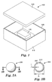
- exemplary enclosure 100 comprises two sections, housing 110 and cover 120.
- Enclosure 100 contains component 140 and a gas environment.
- an enclosure may comprise any number of sections connected by any known means including, for example, mechanical fasteners (for example, screws, bolts, rivets), welds, and/or adhesives.
- a gasket may be positioned at the seams to reduce leaks.
- the gasket may be an adhesive gasket, which is capable of connecting sections of the enclosure and sealing the resulting seam. Referring to FIG. 1, adhesive gasket 130 connects cover 120 to housing 110.
- the enclosure is filled with one or more inert gases.
- an "inert" gas is one that exhibits substantially no chemical reaction with the components within the enclosure and other materials (for example, gases) within the enclosure under typical use conditions (for example, temperature and pressure). Any inert gas may be used. Exemplary inert gases include helium, neon, argon, krypton, and nitrogen. In some embodiments, a low-density inert gas (for example, helium) is desirable.
- the enclosure is filled with one or more reactive gases.
- a "reactive" gas is one that undergoes a reaction with at least one of the components within the enclosure, or other materials (for example, gases) within the enclosure under typical use conditions (for example, temperature and pressure). Any known reactive gas may be used.
- a reductive gas may be used to react with oxidizing gases in the enclosure.
- the use of a reductive gas to scavenge oxidizing gases will prolong the life of the components within the enclosure.
- Exemplary reactive gases include hydrogen, oxygen, carbon monoxide, formaldehyde, diborane, and ammonia. In some embodiments, the reactive gas is not hydrogen.
- any known gas may be used depending, for example, on the desired environment within the enclosure.
- an inert gas for example, helium
- a reactive gas for example, a reductive gas may be used.
- a particular gas may be inert in one application but reactive in another due to, for example, changes in materials, temperature, or pressure.
- carbon dioxide may be an inert gas, while in other embodiments carbon dioxide may be a reactive gas.
- the relative amount of a particular gas within an enclosure can be defined by the mole fraction of that gas (that is, the number of moles of the particular gas relative to the total number of moles of gas) within the enclosure.
- the relative amount of a particular gas within an enclosure may be expressed as the partial pressure of that gas within the enclosure, wherein the partial pressure of a gas is equal to mole fraction of that gas multiplied by the total pressure within the enclosure.
- the relative amount of the desired gas(es) within an enclosure decreases over time, limiting the useful life of the components within the enclosure. For example, reactive gases will be consumed over time, ambient gases may leak or diffuse into the enclosure, and/or desired gases may leak or diffuse out of the enclosure.
- the depletion rate of a particular gas within an enclosure is defined as the rate at which the relative amount of that gas decreases with time (for example, the rate at which the partial pressure of that gas decreases with time).
- the depletion rate will increase with, for example, an increase in the rates at which the particular gas leaks and/or diffuses out of the enclosure, an increase in the rates at which other gases leak or diffuse into the enclosure, and, for reactive gases, an increase in the rate at which the particular gas reacts.
- the depletion rate of a particular gas within an enclosure is also affected by its replenishment rate, that is, the rate at which the particular gas is replenished.
- the desired gas within the enclosure is internally replenished by positioning a gas source within the enclosure.
- the desired gas within the enclosure is internally replenished by positioning a gas source between sections of the enclosure. This gas source comprises one or more gases contained within a permeable membrane.
- Bubble 200 comprises membrane 210 having a mean thickness T, and a mean diameter D.
- One or more gases are stored within cavity 220.
- the gas may be stored within the bubbles at elevated pressure.
- the storage pressure is at least about 200 kPa (29 psi) (in some embodiments, at least about 1000 kPa (145 psi), at least about 1725 kPa (250 psi), or even at least about 2750 kPa (400 psi)).
- bubbles may be of any shape, size (for example, mean diameter), size distribution, volume, membrane thickness, density, and aspect ratio (ratio of mean diameter to mean wall thickness for a spherical bubble).
- the bubbles can have arbitrary shapes.
- the bubbles are substantially spherical so as to withstand maximum internal pressures.
- Other shapes include any geometric three dimensional polygon with arbitrary numbers of sides including, for example, cubes, cylinders, hemispheres, hemicylinders, pyramids, and the like.
- the bubbles can have a distribution of sizes (for example, diameters or volumes).
- the distribution can be described by a particle size characterization function, for example, Gaussian, Lorentzian, or log-normal.
- the distribution can be unimodal (including, for example, only one size of particles) or multimodal (for example, bimodal, trimodal, etc.). Generally, multimodal distributions provide increased packing density.
- the bubbles can have a median diameter (that is, 50 th percentile) of at least about 1 micrometer ( ⁇ m) (in some embodiments, at least about 5 ⁇ m, at least about 10 ⁇ m, or even at least about 20 ⁇ m). In some embodiments, the bubbles can have an average size of at less than about 5000 ⁇ m (in some embodiments, less than about 1000 ⁇ m, less than about 500 ⁇ m, less than about 100 ⁇ m, or even less than about 50 ⁇ m). In some embodiments, the bubbles have an average internal volume per bubble of at least about 50 cubic micrometers (in some embodiments, at least about 250 cubic micrometers, or even at least about 500 cubic micrometers). In some embodiments, the bubbles have an average volume of less than about one billion cubic micrometers (in some embodiments, less than about 250 million cubic micrometers, or less than 50 million cubic micrometers, or even less than 5 million cubic micrometers).
- membrane 210 may comprise any material(s) provided it is permeable to the gas stored within the bubble at use conditions (for example, temperature).
- Exemplary membranes include glass, glass/ceramic, metal (for example, Ti and Pd), metal oxide, multiple layers of metal and metal oxide, other metal compounds such as nitrides, carbides, and silicides, alloys, and polymeric materials.
- the membrane comprises a plurality of layers of the same or different materials. Selection of the material(s) used for the membrane may depend on, for example, permeability (that is, rate of transport of the stored gas through the membrane), density, and mechanical properties (for example, tensile strength, crush resistance).
- permeability of a gas through a particular membrane material can be determined by routine experimentation. (See, for example, ASTM test methods D737-96 and D3985.) Permeation rates are also reported in the literature. (See, for example, Vacuum Technology, Roth, A., North Holland Publishing Co., pages 164 and 166 (1976 ).) Generally, permeability may depend on, for example, the composition of the membrane, the thickness of each layer, and the presence of pinholes, voids, or patterns in one or more of the layers.
- the average thickness of the membrane is at least 0.01 ⁇ m (in some embodiments, at least 0.1 ⁇ m, or even at least 0.5 ⁇ m). In some embodiments, the average thickness of the membrane is less than 20 ⁇ m (in some embodiments, less than 5.0 ⁇ m, or even less than 2.0 ⁇ m). In some embodiments, the bubbles can have a distribution of membrane thicknesses. In some embodiments, the average permeation rate of a plurality of bubbles can be controlled by adjusting the distribution of membrane thicknesses.
- Glass bubbles can be made by any known method. (See, for example, U.S. Patent Nos. 3,365,315 and 4,767,726 .)
- glass bubbles useful in the present invention are commercially available, including, for example, those available under the trade name Scotchlite Glass Bubbles from 3M Company, St. Paul, Minnesota. Ceramic bubbles are also commercially available including, for example, those available from 3M Company under the trade names Z-Light Spheres and Zeeospheres.
- the permeability of a membrane may be adjusted by altering properties of the membrane. Generally, an increase in membrane thickness or density decreases permeability. Also, one or more layers may be applied to a surface of the membrane to reduce permeability.
- inorganic materials for example, metals and/or metal oxides
- metals such as gold, silver, copper, tin, zinc, aluminum, tungsten, chromium, zirconium, titanium, nickel, palladium and/or platinum may be used.
- Other useful materials include carbon and silicon and alloys containing metals and/or metalloids.
- titanium nitride, tin oxide, or aluminum oxide may be used.
- the thickness of the layer(s) is at least about 0.2 nanometers (nm) (in some embodiments, at least about 0.3 nm, at least about 0.5 nm, or even at least about 1 nm). In some embodiments, the thickness of the layer(s) is less than about 20 nm (in some embodiments, less than about 10 nm, or less than about 5 nm, or even less than about 2 nm).
- voids or pinholes may be present in one or more layers.
- one or more of the layers may be applied to only a portion of the membrane.
- only a portion of the bubbles will have additional layers applied to the membrane. Generally, each of these properties may be adjusted to control the average permeation rate of a plurality of bubbles.
- any known method may be used to apply thin film layers of inorganic materials to glass bubbles (see, for example, U.S. Patent No. 4,618,525 ) including for example, physical vapor deposition (sputter coating, evaporative coating, and cathodic arc deposition), chemical vapor deposition, electroless plating, and wet chemical means such as sol-gel coating.
- Commercially available coated glass bubbles include, for example, those available under the trade name Conduct-O-Fill from Potters Industries, Inc., Valley Forge, Pennsylvania.
- the surface of a bubble may be treated with, for example, organic materials, for example, epoxy silane and methacrylate chromic chloride.
- organic materials for example, epoxy silane and methacrylate chromic chloride.
- exemplary surface treated bubbles include those available from 3M Company under the trade name Scotchlite Glass Bubbles (for example, D32/4500, H20/1000, and A20/1000).
- the gas source may be incorporated in the enclosure by any known means.
- bubbles may be placed loose within the enclosure.
- the bubbles may be placed in a permeable container, for example, a polymeric bag or pouch, and the pouch placed within the enclosure.
- the polymeric pouch may be coated with, for example, a metal or metal oxide, to control the rate of permeability of the inert gas through the walls of the pouch.
- the bubbles may be incorporated with a resin.
- the bubbles may be adhered to the surface of a resin and/or partially encapsulated in the resin.
- a portion of the bubbles may be fully encapsulated in the resin.
- substantially all (for example, greater than 90% by weight, in some embodiments, greater than 95%, or even greater than 99%) of the bubbles may be fully encapsulated in the resin.
- any known resin may be used.
- the resin may be selected to control the rate of permeation of gas from the interior of the bubbles, through the resin, to the interior of the enclosure.
- Exemplary resins include acrylates, methacrylates, epoxies, silicones, olefins, and polyesters.
- the resin may be thermoplastic, thermosetting, elastomeric, or a thermoplastic elastomer.
- a highly crosslinked resin for example, an epoxy
- highly crystalline resins for example, polyethylene and ethylene vinyl alcohol
- the resin may be curable by, for example, moisture, heat, actinic radiation (for example, visible light, UV), or e-beam.
- the bubbles may be incorporated into the resin by any known means including, for example, mixing the bubbles into a melted resin or a solution (for example, an aqueous or solvent solution) of the resin.
- the bubbles may be milled with a resin using, for example, a two-roll mill.
- the bubbles may be added to an extruder and compounded with the resin.
- the bubbles may be added to a pre-polymeric mixture that is subsequently polymerized to form the resin.
- the resin may be an adhesive.
- the bubble-filled adhesive may be used to connect parts within the enclosure, and/or to connect sections of the enclosure.
- the resin may be used to form a gasket used with the enclosure (for example, placed between sections of the enclosure).
- the bubble-containing resin may be applied (for example, coated) on to one or more interior surfaces of the enclosure.
- the resin may be applied to one or more surfaces of a component within the enclosure.
- the resin may include other materials including, for example, silica, talc, carbon black, electrically and/or thermally conductive particles, rheology modifiers (for example, thixotropic agents), tackifiers, plasticizers, foaming agents, fibers, solid and/or hollow beads, dyes, and/or pigments.
- rheology modifiers for example, thixotropic agents
- tackifiers for example, plasticizers
- foaming agents for example, fibers, solid and/or hollow beads, dyes, and/or pigments.
- gas may be stored in a permeable container, for example, a pouch, and the pouch may be placed in the enclosure.
- the pouch may comprise a coated or uncoated polymer film. Coatings include organic and inorganic (for example, metal and/or metal oxide) materials.
- the replenishment rate provided by a gas source comprising the desired gas contained within a permeable membrane is a function of a variety of parameters including, for example, the average permeability of the membrane, the total volume of desired gas contained within the permeable membrane, the partial pressure of the desired gas in the enclosure, the resin in which the gas-containing permeable membrane is enclosed, if any, and the temperature and pressure within the enclosure.
- the replenishment rate may vary with time as the desired gas diffuses through the permeable membrane.
- the replenishment rate should be greater than or equal to the sum of the rates at which the desired gas is removed from the enclosure by, for example, reaction, leaking and/or diffusion.
- the replenishment rate should be sufficient to maintain the partial pressure of the desired gas within the enclosure at least 20% of its initial partial pressure, in some embodiments at least 50%, and, in some embodiments, at least 75%, or even at least 90% of its initial partial pressure.
- the partial pressure of the desired gas within the enclosure should be maintained for the working life of the components within the enclosure. In some embodiments, the partial pressure of the desired gas within the enclosure should be maintained for at least one year, in some embodiments, at least two years, in some embodiments, at least three years, and even at least five years, or even longer.
- Bubbles available under the tradename Scotchlite Glass Bubbles S60/10,000 from 3M Company were used.
- the glass is reported to be 70-80% SiO 2 , 8-15% CaO, 3-8% Na 2 O, and 2-6% B 2 O 3 .
- the average bubble density is reported to be 0.60 +/- 0.02 g/cc, with a median diameter (that is, 50 th percentile) of 30 micrometers, an average wall thickness of 1.3 micrometers and an internal diameter of 28 micrometers.
- a sample of uncoated bubbles was coated with a thin (approximately 1000 Angstrom) layer of aluminum.
- the bubbles were agitated while being coated with a flux of metal atoms from a sputtering source.
- a film of aluminum oxide was deposited upon the aluminum layer via reactive sputter-deposition involving the concurrent addition of oxygen during aluminum sputtering.
- the density of the coated bubbles was 0.65g/cm 3 .
- both uncoated and aluminum coated bubbles were filled.
- the coated bubbles were filled after the coatings had been applied.
- bubbles may be filled with gas either before or after one or more coatings have been applied.
- the bubbles were weighed into a 2.54 cm x 2.54 cm (1 inch x 1 inch) plastic weighing boat, which was then placed into a containment tube containing ambient air.
- the volume of the containment tube was approximately 600 mL.
- the joints of the tube were sealed with high-vacuum grease. Examples 1 and 3 were held at ambient temperature (21 °C), while Examples 2 and 4 were placed in a 70 °C oven.
- GC Gas chromatography
- a sample of helium-filled uncoated bubbles was placed in a containment tube as described above.
- the containment tube and bubbles were placed in a 150 °C oven for one week.
- the tube was then removed from the oven, allowed to cool to room temperature, and the atmosphere within the tube analyzed using GC, as described above.
- the bubbles were found to contain 250 mL of helium per gram of bubbles.
- a sample of helium-filled uncoated bubbles was placed in a containment tube and placed in a 600 °C oven for ten minutes. The tube was then removed from the oven, allowed to cool to room temperature, and the atmosphere within the tube analyzed using GC, as described above. The bubbles contain 191 mL of helium per gram of bubbles.
- a balloon #1032 latex balloon obtained from National Latex Products
- glycerol analytical grade glycerol obtained from EM Science Corp.
- the initial volume of the balloon filled with the bubbles and glycerol was measured by immersion in 10W-30 engine oil contained in a graduated cylinder.
- the balloon and its contents were subjected to sufficient isostactic pressure (138 MPa (20,000 psi)) to fracture the bubbles releasing the helium stored inside.
- the increase in volume of the balloon was determined by measuring the displacement of the oil in the graduated cylinder.
- the first sample which was tested within one hour after being removed from the autoclave, contained 18 mL of helium in a 0.417 g sample (43.2 mL/g). Based on this volume, the pressure inside the filled bubbles was calculated to be 2.74 MPa (397 psi).
- the second sample which was tested 24 hours after being removed from the autoclave, contained 8 mL of helium in a 0.364 g sample (22.0 mL/g). The pressure inside the filled bubbles was calculated to be 1.76 MPa (255 psi).
Landscapes
- Separation Using Semi-Permeable Membranes (AREA)
- Filling Or Discharging Of Gas Storage Vessels (AREA)
- Catching Or Destruction (AREA)
- Packages (AREA)
Applications Claiming Priority (2)
| Application Number | Priority Date | Filing Date | Title |
|---|---|---|---|
| US57437004P | 2004-05-25 | 2004-05-25 | |
| PCT/US2005/016153 WO2005117018A2 (en) | 2004-05-25 | 2005-05-10 | Internally replenished enclosure |
Publications (2)
| Publication Number | Publication Date |
|---|---|
| EP1756831A2 EP1756831A2 (en) | 2007-02-28 |
| EP1756831B1 true EP1756831B1 (en) | 2007-11-14 |
Family
ID=34970470
Family Applications (1)
| Application Number | Title | Priority Date | Filing Date |
|---|---|---|---|
| EP05752082A Expired - Lifetime EP1756831B1 (en) | 2004-05-25 | 2005-05-10 | Internally replenished enclosure |
Country Status (8)
| Country | Link |
|---|---|
| US (2) | US7538972B2 (enExample) |
| EP (1) | EP1756831B1 (enExample) |
| JP (1) | JP2008500677A (enExample) |
| CN (1) | CN1961375B (enExample) |
| AT (1) | ATE378680T1 (enExample) |
| DE (1) | DE602005003359T2 (enExample) |
| TW (1) | TW200617896A (enExample) |
| WO (1) | WO2005117018A2 (enExample) |
Cited By (1)
| Publication number | Priority date | Publication date | Assignee | Title |
|---|---|---|---|---|
| US12057144B2 (en) | 2019-08-22 | 2024-08-06 | Donaldson Company, Inc. | Gas replenishment component for an enclosure |
Families Citing this family (35)
| Publication number | Priority date | Publication date | Assignee | Title |
|---|---|---|---|---|
| US7365937B2 (en) * | 2003-07-24 | 2008-04-29 | Seagate Technology Llc | Inert gas atmosphere replenishment structure |
| DE102005041863A1 (de) * | 2005-09-02 | 2007-03-29 | Ashland-Südchemie-Kernfest GmbH | Borsilikatglashaltige Formstoffmischungen |
| US7961427B2 (en) * | 2007-05-22 | 2011-06-14 | Galleon International Corporation | High performance computer hard disk drive with a carbon overcoat and method of improving hard disk performance |
| US8014167B2 (en) * | 2007-09-07 | 2011-09-06 | Seagate Technology Llc | Liquid crystal material sealed housing |
| US8094409B2 (en) | 2008-05-28 | 2012-01-10 | Hitachi Global Storage Technologies, Netherlands B.V. | Method and system for monitoring gas in sealed hard disk drives with feedback |
| US8999245B2 (en) | 2009-07-07 | 2015-04-07 | Tricorn Tech Corporation | Cascaded gas chromatographs (CGCs) with individual temperature control and gas analysis systems using same |
| US8707760B2 (en) | 2009-07-31 | 2014-04-29 | Tricorntech Corporation | Gas collection and analysis system with front-end and back-end pre-concentrators and moisture removal |
| US8978444B2 (en) | 2010-04-23 | 2015-03-17 | Tricorn Tech Corporation | Gas analyte spectrum sharpening and separation with multi-dimensional micro-GC for gas chromatography analysis |
| US20110312858A1 (en) * | 2010-06-21 | 2011-12-22 | Holt Jonathan W | Composition and methods for oilfield application |
| US8279552B2 (en) * | 2010-06-22 | 2012-10-02 | Hitachi Global Storage Technologies, Netherlands B.V. | Hermetically sealing a hard disk drive |
| US8934194B2 (en) * | 2011-01-09 | 2015-01-13 | Erhard Schreck | System and method for maintaining a low density gas environment in a disk drive |
| US9190115B2 (en) | 2011-04-28 | 2015-11-17 | Entrotech, Inc. | Method of assembling a disk drive |
| US9466335B2 (en) | 2011-04-28 | 2016-10-11 | Entrotech, Inc. | Hermetic hard disk drives comprising integrally molded filters and related methods |
| US8837080B2 (en) | 2011-04-28 | 2014-09-16 | Entrotech, Inc. | Hard disk drives with composite housings and related methods |
| US8599514B2 (en) | 2011-04-28 | 2013-12-03 | Entrotech, Inc. | Stabilization of components within hard disk drives and related methods |
| US8760797B1 (en) | 2013-06-13 | 2014-06-24 | Seagate Technology Llc | Contamination control for a disc drive |
| US20150294691A1 (en) * | 2014-04-09 | 2015-10-15 | HGST Netherlands B.V. | Sealed disk media enclosure |
| US10079043B2 (en) | 2014-04-22 | 2018-09-18 | Entrotech, Inc. | Method of sealing a re-workable hard disk drive |
| EP3152757A1 (en) | 2014-06-09 | 2017-04-12 | Entrotech, Inc. | Laminate-wrapped hard disk drives and related methods |
| US9601161B2 (en) | 2015-04-15 | 2017-03-21 | entroteech, inc. | Metallically sealed, wrapped hard disk drives and related methods |
| US9721620B2 (en) | 2015-12-09 | 2017-08-01 | Western Digital Technologies, Inc. | Hermetic sealing of hard disk drive using laminated film seal |
| US9721619B2 (en) | 2015-12-09 | 2017-08-01 | Western Digital Technologies, Inc. | Hermetic sealing of hard disk drive using laminated film seal |
| US9704539B2 (en) | 2015-12-09 | 2017-07-11 | Western Digital Technologies, Inc. | Hermetic sealing of hard disk drive using laminated film seal |
| US9570114B1 (en) | 2016-01-15 | 2017-02-14 | HGST Netherlands B.V. | Laminated film-packed hard disk drive for hermetic sealing |
| US9916872B1 (en) * | 2016-12-20 | 2018-03-13 | Western Digital Technologies, Inc. | Double-barrier vacuum seal for sealed data storage system |
| US10262698B2 (en) | 2017-06-21 | 2019-04-16 | Western Digital Technologies, Inc. | Intermittent operation of compartmented pneumatics for sealed data storage system |
| US10971195B2 (en) * | 2018-08-23 | 2021-04-06 | Seagate Technology Llc | Cavity seal and moisture control |
| US10706893B1 (en) * | 2019-07-31 | 2020-07-07 | Seagate Technology Llc | Method of temporarily sealing data storage device and device |
| US11355161B2 (en) | 2019-08-07 | 2022-06-07 | Seagate Technology Llc | Electronic device that includes a composition that can release and optionally generate a gaseous oxidizing agent component into an interior space of the electronic device, and related subassemblies and methods |
| US11783867B2 (en) | 2019-08-07 | 2023-10-10 | Seagate Technology Llc | Electronic device that includes a composition that can actively generate and release a gaseous oxidizing agent component into an interior space of the electronic device, and related subassemblies and methods |
| US11763853B2 (en) | 2019-08-07 | 2023-09-19 | Seagate Technology Llc | Electronic device that includes a composition that can actively generate and release a gaseous oxidizing agent component into an interior space of the electronic device, and related subassemblies and methods |
| US11348619B2 (en) * | 2020-07-16 | 2022-05-31 | Western Digital Technologies, Inc. | Dual gasket for manufacturing of hermetically-sealed hard disk drive |
| US11270739B1 (en) * | 2021-02-09 | 2022-03-08 | Seagate Technology Llc | Electronic device that includes one or more reactants that generate a gaseous oxidizing agent component inside the electronic device, and related subassemblies and methods |
| US12424248B2 (en) | 2023-10-23 | 2025-09-23 | Western Digital Technologies, Inc. | Devices and methods for metal organic framework (MOF) based oxygen replenishment in data storage devices |
| US12406699B1 (en) * | 2024-02-19 | 2025-09-02 | Western Digital Technologies, Inc. | Passive and active gas compensation techniques for data storage devices |
Family Cites Families (25)
| Publication number | Priority date | Publication date | Assignee | Title |
|---|---|---|---|---|
| US2797201A (en) | 1953-05-11 | 1957-06-25 | Standard Oil Co | Process of producing hollow particles and resulting product |
| US2892508A (en) | 1957-04-17 | 1959-06-30 | Bell Telephone Labor Inc | Separation of gases by diffusion |
| NL232500A (enExample) | 1957-10-22 | |||
| US3184899A (en) | 1958-12-31 | 1965-05-25 | Standard Oil Co | Helium separation |
| US3365315A (en) | 1963-08-23 | 1968-01-23 | Minnesota Mining & Mfg | Glass bubbles prepared by reheating solid glass partiles |
| US4211537A (en) * | 1978-07-24 | 1980-07-08 | Teitel Robert J | Hydrogen supply method |
| US4367503A (en) | 1980-12-24 | 1983-01-04 | International Business Machines Corporation | Fermetically sealed disk file |
| GB2139616B (en) * | 1983-05-13 | 1987-04-01 | Glaverbel | Gas-filled glass beads |
| US4556969A (en) | 1984-12-28 | 1985-12-03 | International Business Machines Corporation | Hermetically sealed disk file |
| US4618525A (en) * | 1985-06-03 | 1986-10-21 | Minnesota Mining And Manufacturing Company | Coated glass microbubbles and article incorporating them |
| US4767726A (en) | 1987-01-12 | 1988-08-30 | Minnesota Mining And Manufacturing Company | Glass microbubbles |
| US5293286A (en) * | 1990-01-19 | 1994-03-08 | Nec Corporation | Magnetic disc apparatus for maintaining an optimum humidity in a head disc assembly |
| JP2769536B2 (ja) * | 1993-09-20 | 1998-06-25 | 株式会社日立製作所 | 磁気ディスク装置 |
| US5756936A (en) | 1994-05-18 | 1998-05-26 | Minnesota Mining And Manufacturing Company | Cylindrical radially shrinkable sleeve for an electrical cable and composition thereof |
| WO1998021772A1 (en) | 1996-11-13 | 1998-05-22 | Minnesota Mining And Manufacturing Company | Storage and delivery of pressurized gases in microbubbles |
| US6317286B1 (en) | 1999-01-29 | 2001-11-13 | Seagate Technology Llc | Diaphragm-sealed disc drive |
| US6392838B1 (en) | 1999-03-30 | 2002-05-21 | Maxtor Corporation | Hermetically sealed data storage device |
| US6560064B1 (en) | 2000-03-21 | 2003-05-06 | International Business Machines Corporation | Disk array system with internal environmental controls |
| US6819517B2 (en) * | 2001-07-31 | 2004-11-16 | Seagate Technology Llc | Disc drive servo track writer gas leak detector and method |
| US6683747B2 (en) | 2001-11-02 | 2004-01-27 | Seagate Technology Llc | Internal disc drive gas reservoir |
| WO2003043011A1 (en) | 2001-11-13 | 2003-05-22 | Seagate Technology Llc | Disc drive gas filling system |
| GB0204946D0 (en) * | 2002-03-04 | 2002-04-17 | Rexam Med Packaging Ltd | Polymeric films and packages produced therefrom |
| US7119984B2 (en) | 2002-06-03 | 2006-10-10 | Seagate Technology Llc | Method and apparatus for a laser-welded disk drive housing |
| US6825930B2 (en) * | 2002-06-04 | 2004-11-30 | Cambridge Research And Instrumentation, Inc. | Multispectral imaging system |
| US7365937B2 (en) * | 2003-07-24 | 2008-04-29 | Seagate Technology Llc | Inert gas atmosphere replenishment structure |
-
2005
- 2005-05-05 US US11/122,835 patent/US7538972B2/en not_active Expired - Fee Related
- 2005-05-10 AT AT05752082T patent/ATE378680T1/de not_active IP Right Cessation
- 2005-05-10 JP JP2007515130A patent/JP2008500677A/ja active Pending
- 2005-05-10 CN CN2005800172327A patent/CN1961375B/zh not_active Expired - Fee Related
- 2005-05-10 DE DE602005003359T patent/DE602005003359T2/de not_active Expired - Lifetime
- 2005-05-10 WO PCT/US2005/016153 patent/WO2005117018A2/en not_active Ceased
- 2005-05-10 EP EP05752082A patent/EP1756831B1/en not_active Expired - Lifetime
- 2005-05-24 TW TW094116901A patent/TW200617896A/zh unknown
-
2009
- 2009-04-17 US US12/425,634 patent/US20090201606A1/en not_active Abandoned
Cited By (2)
| Publication number | Priority date | Publication date | Assignee | Title |
|---|---|---|---|---|
| US12057144B2 (en) | 2019-08-22 | 2024-08-06 | Donaldson Company, Inc. | Gas replenishment component for an enclosure |
| US12512129B2 (en) | 2019-08-22 | 2025-12-30 | Donaldson Company, Inc. | Gas replenishment component for an enclosure |
Also Published As
| Publication number | Publication date |
|---|---|
| US20050264926A1 (en) | 2005-12-01 |
| US7538972B2 (en) | 2009-05-26 |
| WO2005117018A2 (en) | 2005-12-08 |
| CN1961375B (zh) | 2012-09-05 |
| ATE378680T1 (de) | 2007-11-15 |
| DE602005003359D1 (de) | 2007-12-27 |
| CN1961375A (zh) | 2007-05-09 |
| JP2008500677A (ja) | 2008-01-10 |
| WO2005117018A3 (en) | 2006-02-09 |
| EP1756831A2 (en) | 2007-02-28 |
| DE602005003359T2 (de) | 2008-09-04 |
| US20090201606A1 (en) | 2009-08-13 |
| TW200617896A (en) | 2006-06-01 |
Similar Documents
| Publication | Publication Date | Title |
|---|---|---|
| EP1756831B1 (en) | Internally replenished enclosure | |
| Boser | Hydrogen sorption in LaNi5 | |
| JP5535621B2 (ja) | 流体容器およびそれに関する方法 | |
| JP5518329B2 (ja) | 水素貯蔵複合材料 | |
| US6030694A (en) | Rigid sheet polytetrafluoroethylene material | |
| IL110156A (en) | Process and composition for purifying semiconductor process gases to remove lewis acid and oxidant impurities therefrom | |
| US4496249A (en) | Method and apparatus for determining relative surface areas of a coated material on a substrate | |
| KR20070016172A (ko) | 내부 보충식 엔클로저 | |
| Kuhs et al. | Gas pressure cells for elastic and inelastic neutron scattering | |
| GB2388173A (en) | Pipe comprising a porous inner wall | |
| Buckley | Influence of chemisorbed films on adhesion and friction of clean iron | |
| Mukherjee et al. | Study on forms of activated carbon related to application in CryosorptionCryopump | |
| US20040197593A1 (en) | Surface modification of porous metal substrates using cold spray | |
| US6244068B1 (en) | Coolant container and its method of manufacture | |
| JP2004059154A (ja) | 封着材料梱包体及び封着材料の梱包方法 | |
| Stakebake | Kinetics for the reaction of hydrogen with plutonium powder | |
| Lowell et al. | Density measurement | |
| Forcey et al. | Tritium permeation barriers in contact with liquid lithium-lead eutectic (Pb 17Li) | |
| Perinic et al. | Development of cryosorption panels for cryopumps | |
| Rubow | Porous metal for aerospace. | |
| Hedin et al. | Automated sample preparation station for studying self-diffusion in porous solids with NMR spectroscopy | |
| CN119573916A (zh) | 液氦温区下气体吸附仪中等效温度的测量方法 | |
| Mattenet et al. | An X‐Ray Thermo‐Pressure Cell For Carbon Dioxide | |
| Fromm | Poisoning of hydrogen reactions | |
| Huot | Kinetics and Thermodynamics: Measurement of H2 Sorption Properties |
Legal Events
| Date | Code | Title | Description |
|---|---|---|---|
| PUAI | Public reference made under article 153(3) epc to a published international application that has entered the european phase |
Free format text: ORIGINAL CODE: 0009012 |
|
| 17P | Request for examination filed |
Effective date: 20061130 |
|
| AK | Designated contracting states |
Kind code of ref document: A2 Designated state(s): AT BE BG CH CY CZ DE DK EE ES FI FR GB GR HU IE IS IT LI LT LU MC NL PL PT RO SE SI SK TR |
|
| 17Q | First examination report despatched |
Effective date: 20070327 |
|
| GRAP | Despatch of communication of intention to grant a patent |
Free format text: ORIGINAL CODE: EPIDOSNIGR1 |
|
| DAX | Request for extension of the european patent (deleted) | ||
| GRAS | Grant fee paid |
Free format text: ORIGINAL CODE: EPIDOSNIGR3 |
|
| GRAA | (expected) grant |
Free format text: ORIGINAL CODE: 0009210 |
|
| AK | Designated contracting states |
Kind code of ref document: B1 Designated state(s): AT BE BG CH CY CZ DE DK EE ES FI FR GB GR HU IE IS IT LI LT LU MC NL PL PT RO SE SI SK TR |
|
| REG | Reference to a national code |
Ref country code: GB Ref legal event code: FG4D |
|
| REG | Reference to a national code |
Ref country code: CH Ref legal event code: EP |
|
| REG | Reference to a national code |
Ref country code: IE Ref legal event code: FG4D |
|
| REF | Corresponds to: |
Ref document number: 602005003359 Country of ref document: DE Date of ref document: 20071227 Kind code of ref document: P |
|
| REG | Reference to a national code |
Ref country code: HK Ref legal event code: DE Ref document number: 1103847 Country of ref document: HK |
|
| PG25 | Lapsed in a contracting state [announced via postgrant information from national office to epo] |
Ref country code: CH Free format text: LAPSE BECAUSE OF FAILURE TO SUBMIT A TRANSLATION OF THE DESCRIPTION OR TO PAY THE FEE WITHIN THE PRESCRIBED TIME-LIMIT Effective date: 20071114 Ref country code: SE Free format text: LAPSE BECAUSE OF FAILURE TO SUBMIT A TRANSLATION OF THE DESCRIPTION OR TO PAY THE FEE WITHIN THE PRESCRIBED TIME-LIMIT Effective date: 20080214 Ref country code: LI Free format text: LAPSE BECAUSE OF FAILURE TO SUBMIT A TRANSLATION OF THE DESCRIPTION OR TO PAY THE FEE WITHIN THE PRESCRIBED TIME-LIMIT Effective date: 20071114 Ref country code: NL Free format text: LAPSE BECAUSE OF FAILURE TO SUBMIT A TRANSLATION OF THE DESCRIPTION OR TO PAY THE FEE WITHIN THE PRESCRIBED TIME-LIMIT Effective date: 20071114 Ref country code: ES Free format text: LAPSE BECAUSE OF FAILURE TO SUBMIT A TRANSLATION OF THE DESCRIPTION OR TO PAY THE FEE WITHIN THE PRESCRIBED TIME-LIMIT Effective date: 20080225 |
|
| NLV1 | Nl: lapsed or annulled due to failure to fulfill the requirements of art. 29p and 29m of the patents act | ||
| PG25 | Lapsed in a contracting state [announced via postgrant information from national office to epo] |
Ref country code: BG Free format text: LAPSE BECAUSE OF FAILURE TO SUBMIT A TRANSLATION OF THE DESCRIPTION OR TO PAY THE FEE WITHIN THE PRESCRIBED TIME-LIMIT Effective date: 20080214 Ref country code: PL Free format text: LAPSE BECAUSE OF FAILURE TO SUBMIT A TRANSLATION OF THE DESCRIPTION OR TO PAY THE FEE WITHIN THE PRESCRIBED TIME-LIMIT Effective date: 20071114 Ref country code: SI Free format text: LAPSE BECAUSE OF FAILURE TO SUBMIT A TRANSLATION OF THE DESCRIPTION OR TO PAY THE FEE WITHIN THE PRESCRIBED TIME-LIMIT Effective date: 20071114 Ref country code: LT Free format text: LAPSE BECAUSE OF FAILURE TO SUBMIT A TRANSLATION OF THE DESCRIPTION OR TO PAY THE FEE WITHIN THE PRESCRIBED TIME-LIMIT Effective date: 20071114 Ref country code: FI Free format text: LAPSE BECAUSE OF FAILURE TO SUBMIT A TRANSLATION OF THE DESCRIPTION OR TO PAY THE FEE WITHIN THE PRESCRIBED TIME-LIMIT Effective date: 20071114 Ref country code: IS Free format text: LAPSE BECAUSE OF FAILURE TO SUBMIT A TRANSLATION OF THE DESCRIPTION OR TO PAY THE FEE WITHIN THE PRESCRIBED TIME-LIMIT Effective date: 20080314 |
|
| REG | Reference to a national code |
Ref country code: CH Ref legal event code: PL |
|
| PG25 | Lapsed in a contracting state [announced via postgrant information from national office to epo] |
Ref country code: AT Free format text: LAPSE BECAUSE OF FAILURE TO SUBMIT A TRANSLATION OF THE DESCRIPTION OR TO PAY THE FEE WITHIN THE PRESCRIBED TIME-LIMIT Effective date: 20071114 |
|
| PG25 | Lapsed in a contracting state [announced via postgrant information from national office to epo] |
Ref country code: DK Free format text: LAPSE BECAUSE OF FAILURE TO SUBMIT A TRANSLATION OF THE DESCRIPTION OR TO PAY THE FEE WITHIN THE PRESCRIBED TIME-LIMIT Effective date: 20071114 Ref country code: CZ Free format text: LAPSE BECAUSE OF FAILURE TO SUBMIT A TRANSLATION OF THE DESCRIPTION OR TO PAY THE FEE WITHIN THE PRESCRIBED TIME-LIMIT Effective date: 20071114 |
|
| EN | Fr: translation not filed | ||
| PG25 | Lapsed in a contracting state [announced via postgrant information from national office to epo] |
Ref country code: BE Free format text: LAPSE BECAUSE OF FAILURE TO SUBMIT A TRANSLATION OF THE DESCRIPTION OR TO PAY THE FEE WITHIN THE PRESCRIBED TIME-LIMIT Effective date: 20071114 Ref country code: SK Free format text: LAPSE BECAUSE OF FAILURE TO SUBMIT A TRANSLATION OF THE DESCRIPTION OR TO PAY THE FEE WITHIN THE PRESCRIBED TIME-LIMIT Effective date: 20071114 Ref country code: RO Free format text: LAPSE BECAUSE OF FAILURE TO SUBMIT A TRANSLATION OF THE DESCRIPTION OR TO PAY THE FEE WITHIN THE PRESCRIBED TIME-LIMIT Effective date: 20071114 |
|
| PLBE | No opposition filed within time limit |
Free format text: ORIGINAL CODE: 0009261 |
|
| STAA | Information on the status of an ep patent application or granted ep patent |
Free format text: STATUS: NO OPPOSITION FILED WITHIN TIME LIMIT |
|
| PG25 | Lapsed in a contracting state [announced via postgrant information from national office to epo] |
Ref country code: PT Free format text: LAPSE BECAUSE OF FAILURE TO SUBMIT A TRANSLATION OF THE DESCRIPTION OR TO PAY THE FEE WITHIN THE PRESCRIBED TIME-LIMIT Effective date: 20080414 |
|
| 26N | No opposition filed |
Effective date: 20080815 |
|
| PG25 | Lapsed in a contracting state [announced via postgrant information from national office to epo] |
Ref country code: FR Free format text: LAPSE BECAUSE OF FAILURE TO SUBMIT A TRANSLATION OF THE DESCRIPTION OR TO PAY THE FEE WITHIN THE PRESCRIBED TIME-LIMIT Effective date: 20080829 |
|
| PG25 | Lapsed in a contracting state [announced via postgrant information from national office to epo] |
Ref country code: MC Free format text: LAPSE BECAUSE OF NON-PAYMENT OF DUE FEES Effective date: 20080531 |
|
| PG25 | Lapsed in a contracting state [announced via postgrant information from national office to epo] |
Ref country code: GR Free format text: LAPSE BECAUSE OF FAILURE TO SUBMIT A TRANSLATION OF THE DESCRIPTION OR TO PAY THE FEE WITHIN THE PRESCRIBED TIME-LIMIT Effective date: 20080215 Ref country code: EE Free format text: LAPSE BECAUSE OF FAILURE TO SUBMIT A TRANSLATION OF THE DESCRIPTION OR TO PAY THE FEE WITHIN THE PRESCRIBED TIME-LIMIT Effective date: 20071114 |
|
| PG25 | Lapsed in a contracting state [announced via postgrant information from national office to epo] |
Ref country code: IE Free format text: LAPSE BECAUSE OF NON-PAYMENT OF DUE FEES Effective date: 20080512 |
|
| PG25 | Lapsed in a contracting state [announced via postgrant information from national office to epo] |
Ref country code: CY Free format text: LAPSE BECAUSE OF FAILURE TO SUBMIT A TRANSLATION OF THE DESCRIPTION OR TO PAY THE FEE WITHIN THE PRESCRIBED TIME-LIMIT Effective date: 20071114 |
|
| GBPC | Gb: european patent ceased through non-payment of renewal fee |
Effective date: 20090510 |
|
| PG25 | Lapsed in a contracting state [announced via postgrant information from national office to epo] |
Ref country code: GB Free format text: LAPSE BECAUSE OF NON-PAYMENT OF DUE FEES Effective date: 20090510 |
|
| PG25 | Lapsed in a contracting state [announced via postgrant information from national office to epo] |
Ref country code: LU Free format text: LAPSE BECAUSE OF NON-PAYMENT OF DUE FEES Effective date: 20080510 Ref country code: HU Free format text: LAPSE BECAUSE OF FAILURE TO SUBMIT A TRANSLATION OF THE DESCRIPTION OR TO PAY THE FEE WITHIN THE PRESCRIBED TIME-LIMIT Effective date: 20080515 |
|
| PG25 | Lapsed in a contracting state [announced via postgrant information from national office to epo] |
Ref country code: TR Free format text: LAPSE BECAUSE OF FAILURE TO SUBMIT A TRANSLATION OF THE DESCRIPTION OR TO PAY THE FEE WITHIN THE PRESCRIBED TIME-LIMIT Effective date: 20071114 |
|
| PG25 | Lapsed in a contracting state [announced via postgrant information from national office to epo] |
Ref country code: IT Free format text: LAPSE BECAUSE OF NON-PAYMENT OF DUE FEES Effective date: 20080531 |
|
| PGFP | Annual fee paid to national office [announced via postgrant information from national office to epo] |
Ref country code: DE Payment date: 20130515 Year of fee payment: 9 |
|
| REG | Reference to a national code |
Ref country code: HK Ref legal event code: WD Ref document number: 1103847 Country of ref document: HK |
|
| REG | Reference to a national code |
Ref country code: DE Ref legal event code: R119 Ref document number: 602005003359 Country of ref document: DE |
|
| REG | Reference to a national code |
Ref country code: DE Ref legal event code: R119 Ref document number: 602005003359 Country of ref document: DE Effective date: 20141202 |
|
| PG25 | Lapsed in a contracting state [announced via postgrant information from national office to epo] |
Ref country code: DE Free format text: LAPSE BECAUSE OF NON-PAYMENT OF DUE FEES Effective date: 20141202 |