EP1755937B1 - Track roller assembly for the crawler chain of a crawler chassis - Google Patents
Track roller assembly for the crawler chain of a crawler chassis Download PDFInfo
- Publication number
- EP1755937B1 EP1755937B1 EP05764220A EP05764220A EP1755937B1 EP 1755937 B1 EP1755937 B1 EP 1755937B1 EP 05764220 A EP05764220 A EP 05764220A EP 05764220 A EP05764220 A EP 05764220A EP 1755937 B1 EP1755937 B1 EP 1755937B1
- Authority
- EP
- European Patent Office
- Prior art keywords
- crawler
- track roller
- chain
- crawler chain
- roller assembly
- Prior art date
- Legal status (The legal status is an assumption and is not a legal conclusion. Google has not performed a legal analysis and makes no representation as to the accuracy of the status listed.)
- Active
Links
Images


Classifications
-
- B—PERFORMING OPERATIONS; TRANSPORTING
- B62—LAND VEHICLES FOR TRAVELLING OTHERWISE THAN ON RAILS
- B62D—MOTOR VEHICLES; TRAILERS
- B62D55/00—Endless track vehicles
- B62D55/08—Endless track units; Parts thereof
- B62D55/14—Arrangement, location, or adaptation of rollers
-
- B—PERFORMING OPERATIONS; TRANSPORTING
- B62—LAND VEHICLES FOR TRAVELLING OTHERWISE THAN ON RAILS
- B62D—MOTOR VEHICLES; TRAILERS
- B62D55/00—Endless track vehicles
- B62D55/08—Endless track units; Parts thereof
- B62D55/30—Track-tensioning means
- B62D55/305—Track-tensioning means acting on pivotably mounted idlers
Definitions
- the present invention generally concerns a track roller assembly for the crawler chain of a crawler chassis and a crawler chassis for a crawler vehicle, in particular for a crane, which has said track roller assembly.
- crawler chains comprising chain links are guided between two track rollers. If a crane or an excavator with a crawler chassis with a crawler chain is moved on uneven terrain, problems can arise however, particularly in the case of depressions and holes in the ground. If the crane for example is turned on the spot and in that case the crawler chain sags in the centre precisely at the location of the depression in the ground, then the situation can occur where the track roller rides up on to the projection of the crawler chain.
- the projections of the crawler chain usually serve for guiding the crawler chain between the track rollers.
- DE 100 36 367 A1 describes a crawler chassis which has a crawler carrier and at least one drive tumbler which can be fixed thereto, an idler wheel, an endless chain, a plurality of track rollers arranged at the lower run, and a direction-changing roller mounted in a mounting support.
- the direction-changing roller is supported resiliently. That however only resolves the problem of avoiding high loadings on the crawler chain when rigging the crane insofar as a rigid arrangement of the drive tumbler and the idler wheel is used and the stress peaks which occur in that situation are reduced.
- DE 101 32 903 A1 discloses a crawler chassis for excavators, in particular for large hydraulic excavators, which has a crawler carrier accommodating a crawler chain, at least one chain wheel and at least one idler wheel, between which the crawler chain is guided if required by way of guide elements and over which the crawler chain can be deflected, and at least one tensioning element for the crawler chain. That arrangement is intended to reduce wear of the crawler chain.
- the idler wheel is of a larger diameter than the chain wheel and the crawler chain is guided in the upper run substantially rectilinear between the idler and chain wheels.
- JP 09254836 A shows a rolling wheel for a rubber crawler.
- a pair of disk-like rolling members is disposed on a rolling wheel and arranged such that the rolling members roll beside projections of the rubber crawler.
- the rolling members have inclined surfaces formed according to the inclination of the sides of the projections.
- the rolling members are adapted to freely rotate coaxially with the rotating shaft of the rolling wheel, and installed opposite to the right and left sides of the projections. Accordingly, if lateral forces act between the rolling wheel and the rubber crawler, the side surface of the projections and the rolling members come into contact with each other, and the contact force can be softened because the rolling members are freely rotateable, though that the mutual abrasion can be reduced.
- a star carrier roller assembly is disclosed used in certain tracked mobile machines.
- the shown star carrier roller assembly includes a carrier roller positioned adjacent to a sprocket having a plurality of teeth.
- the sprocket is attached to the carrier roller to ensure rotation of the carrier roller even if undesirable substances become attached quite often inhibiting rotation of the carrier rollers.
- Such a stair carrier roller assembly should limit the wear of the carrier roller.
- a similar star carrier roller assembly is shown in DE 296 16 753 U1 and DE 196 40 145 A1 . Both documents merely show an assembly comprising a star carrier roller for carrying the upper part of a crawler chain. In this case, the star carrier roller is fixedly mounted on a shaft for rotating together with the same.
- JP 05039065 A shows a wheel slip-off preventing mechanism for a rubber crawler.
- a wheel slip-off preventing mechanism comprises a supporting part perpendicular to the longitudinal direction of a rubber crawler.
- the supporting part is installed on machine body, and a swing member which can move at least in the vertical direction is fitted on the supporting part.
- the swing member is installed between a pair of angular parts projecting on the inner peripheral surface of the rubber crawler or having the angular part interposed.
- the supporting part is a shaft body, and the swing member fitted on the shaft body is fitted with a free hole having a large diameter than the thickness of the shaft body.
- the swing member travels in contact with the inner peripheral surface of the rubber crawler, and even in the case with the rubber crawler and the machine body are relatively separated in comparison with the contacting travelling, the swing can follow the rubber crawler inside.
- a crawler belt slippage preventing structure is disclosed in JP 10035549 A .
- This known crawler belt slippage preventing structure comprises a plurality of Y-shaped branched crawler belt slippage preventing projections formed in the center part of a crawler belt.
- a pair of front and rear lower side rolling wheels is arranged in the lower part of a frame through a rolling wheel swing motion supporter. Projecting fitting recess parts in which the crawler belt slippage preventing projections are fitted, are formed between rolling wheel main bodies.
- An elastic crawler belt slippage preventing body is suspended between a pair of front and rear rolling wheel supporting boss parts of the rolling wheel swing motion supporter.
- a swelled part of the crawler belt slippage preventing body is arranged between the crawler belt slippage preventing projections and brought into contact with the inner circumferential surface of the crawler belt main body, so that the crawler belt can be prevented from being slipped from the lower side rolling wheels.
- JP 10119834 A shows a running crawler guide.
- the running crawler guide comprises a pair of front rolling wheels and a pair of rear rolling wheels. Each pair of rolling wheels is vertically movable.
- a vertically movable guiding body is provided between the front and rear rolling wheels. The guiding body projects between projections formed on the rail of the crawler track.
- JP 61064588 A shows a track roller of a crawler travelling apparatus.
- Outer collars are integrally formed onto the both outer sides of a roller and arranged so as to be positioned onto the both outer sides of a pair of projections arranged in parallel on the rail of the crawler at the center of a crawler.
- a middle collar is concentrically formed integrally with the both outer collars so as to be positioned in the cavity between the pair of projections.
- a track roller assembly for a crawler chain the track roller assembly being adapted to be mounted in a crawler carrier.
- the inventive track roller assembly comprises at least two spaced track roller portions with running surfaces for running on the crawler chain, and a starshaped element for guiding the track roller assembly on the crawler chain.
- the star-shaped element is mounted freely rotatably between the at least two track roller portions, and provided with a plurality of teeth, wherein the teeth co-operate with the crawler chain in such a way that on rolling over chain links of the crawler chain they engage into corresponding gaps in the crawler chain.
- the teeth extend beyond the running surfaces of the at least two track roller portions and between projections of the crawler chain such that it is ensured that the crawler chain is not displaced laterally relative to the track roller portions and does not roll up on to the projections of the crawler chain.
- the provision of the star-shaped element provides that it is possible to avoid the track roller portions running up on to the projections on the crawler chain when the chain experiences inclined positioning on uneven terrain or sags over a depression in the ground.
- the star-shaped element holds the track roller assembly on the correct line in addition to guidance for the track roller portions by the projections of the crawler chain so that when the crawler carrier moves downwardly on to the chain links of the crawler chain the track roller portions remain in the guidance of the projections and cannot run up thereonto. It is possible in that way to avoid excessive wear and also damage to the crawler chain and to the track rollers which can occur as a consequence of such interim situations.
- the service life of the crawler chain can be prolonged in that way, whereby the operating costs of the excavator or crane which has the track roller assembly according to the invention can also be reduced. Due to the fact that the star-shaped wheel is supported freely rotatably the crawler chain drives the star-shaped element independently from the track roller portions such that even if the track roller portions do not rotate a suitable guidance is ensured.
- the star-shaped element is mounted freely rotatably on a shaft.
- the crawler carrier with the star-shaped element and the track roller portions moves relative to the chain links of the crawler chain, which rest on the ground.
- the star-shaped element experiences a force component by way of one of the chain links of the crawler chain so that the star-shaped element rotates on the shaft which is common to the track roller assemblies.
- the star-shaped element may have the form of for example a star wheel.
- the star-shaped element is provided with prongs or teeth which form guide means.
- the star-shaped element can have five teeth; it is however also possible to provide any other configuration which is suitable for co-operating with corresponding recesses or gaps in the crawler chain.
- a track roller assembly for a crawler chain, the track roller assembly being adapted to be mounted in a crawler carrier.
- This track roller assembly comprises at least two spaced track roller portions with running surfaces for running on the crawler chain and an idling roller for guiding the track roller assembly on the crawler chain.
- the idling roller is mounted in front of the at least two track roller portions and the idling roller is pivotally mounted on a shaft and remains in contact with the crawler chain such that it is ensured that the crawler chain is not displaced laterally relative to the track roller portions and does not roll up on to the projections of the crawler chain.
- the idling roller afford security and stability in order to guarantee tracking truth with only a slight level of chain play.
- the idling roller can rotate freely on the common shaft with the track roller portions.
- the crawler carrier with the idling roller and the track roller portions moves relative to the chain links which are resting on the ground. If now the crawler chain is sagging or if a chain link of the crawler chain, for example the base plate, is in an inclined position relative to the track roller portions, the idling roller ensures that the crawler chain is not displaced laterally relative to the track roller portions and does not run up on to the projections.
- the idling roller is in the form of a pair of rollers which can rotate freely on a front shaft of the track roller portions.
- the pair of rollers stabilises the track roller portions and gives additional security for ensuring tracking fidelity of the track roller assembly on the crawler chain.
- the pair of rollers can rotate freely on a front shaft and can be pivotally arranged on the shaft which extends through the track roller portions. In the situation where the chain sinks, the pair of rollers moves downwardly. In that case, guidance for the chain is still maintained by virtue of the fact that the projections of the chain are still guided between the two rollers of the pair of rollers.
- the rollers of the first guide means are preferably so arranged that they can carry lateral forces of the chain.
- a crawler chassis for for example a lattice jib crane.
- the crawler chassis comprises a crawler carrier, a crawler chain having two rows of projections provided on an inside of the crawler chain, and at least one track roller assembly including at least two track roller portions with running surfaces for running on the crawler chain besides the two rows of projections, and a star-shaped element mounted freely rotatably on a shaft on the crawler carrier of the crawler chassis between the at least two track roller portions.
- the star-shaped element of the at least one track roller assembly co-operates with the crawler chain to prevent lateral displacement of the crawler chain relative to the track roller assembly such that it is ensured that the crawler chain is not displaced laterally relative to the track roller portions and does not roll up on to the projections of the crawler chain.
- a crawler chassis comprises a crawler carrier, a crawler chain having at least one row of projections provided on an inside of the crawler chain, at least one track roller assembly including at least two track roller portions with running surfaces for running on the crawler chain besides the at least one row of projections, and an idling roller for guiding the track roller assembly on the crawler chain.
- the idling roller is pivotally mounted with respect to the track roller portions and is arranged in front of the at least two track roller portions and is remaining in contact with the crawler chain such that it is ensured that the crawler chain is not displaced laterally relative to the track roller portions and does not roll up on to the projections of the crawler chain.
- the track roller assembly of the crawler chassis may have at least two track roller portions with running surfaces for running on the crawler chain and at least one track roller portion which is arranged axially between the at least two track roller portions and whose periphery is reduced in relation to the at least two track roller portions.
- the crawler chassis is of such a configuration that the maximal play between the star shaped element or the idling roller and the crawler chain is less than the maximal play between the track roller portions and the crawler chain.
- the idling roller has an outer peripheral surface which is formed such that the at least one row of projections of the crawler chain is laterally guided by the idling roller.
- two rows of projections are arranged in mutually spaced relationship on the crawler chain and the idling roller of the track roller assembly is in the form of a pair of rollers which can rotate freely on a front shaft and which are arranged with a gap between it.
- the two rollers are arranged such that the two rows of projections project into the gap between the two rollers.
- the at least two track roller portions are freely rotatably mounted on a shaft and the idling roller of the track roller assembly is pivotally mounted on the shaft.
- the crawler chassis is equipped with a crawler chain which is in the form of an endless chain.
- Fig. 1 shows a view in section of a known track roller assembly 12.
- a double track roller or a track roller comprising two track roller portions 2, 2' is mounted by way of a shaft 4 on a crawler carrier 1 of the crawler chassis.
- the track roller assembly 12 rests on a crawler chain 13 which is composed of individual chain links 3.
- the crawler chain 13 also has a pair of projections 7 and two rows of projections, respectively which are arranged in mutually spaced relationship on the inside of the chain links 3.
- the spacing of the projections 7 is so selected that the projections can serve as a guide for the track roller portions 2, 2' so that the track roller portions 2, 2' run against the outside of the projections 7.
- Fig. 1 the crawler chain 13 is shown in a condition of lying flat on the ground, with the track roller assembly 12 being disposed in its correct position or tracking line with respect to the crawler chain 13 so that, upon movement of the vehicle with crawler drive such as for example a lattice jib crane (not further shown here) which uses that track roller assembly 12 or upon corresponding movement of the track roller assembly 12 on the crawler chain 13, it is not damaged or destroyed.
- crawler drive such as for example a lattice jib crane (not further shown here) which uses that track roller assembly 12 or upon corresponding movement of the track roller assembly 12 on the crawler chain 13, it is not damaged or destroyed.
- Fig. 2 shows the same known track roller assembly 12, but in this case the crawler chain 13 is in an inclined position, as can be the case for example on uneven terrain. In this situation the track roller portion 2' has rolled up on to the projection 7 of the crawler chain 13. In that condition, there can be both damage to the crawler chain 13 and also to the track roller portions 2, 2' of the track roller assembly 12.
- Fig. 3 to 6 show a side view of an embodiment by way of example of the invention in a situation involving ongoing movement of the track roller assembly 12 relative to the crawler chain 13.
- the track roller assembly 12 has two track roller portions 5, 5' with running surfaces for running on the crawler chain 13.
- a further track roller portion 14 of reduced periphery is arranged axially between the two track roller portions 5, 5'.
- a star-shaped element 6 Arranged on the track roller portion 14 of reduced periphery and between the track roller portions 5, 5' is a star-shaped element 6 with five teeth 6', 6'', 6''', 6'''', 6''''.
- the star-shaped element 6 which for example can be in the form of a star wheel can rotate freely on the shaft 4.
- the crawler carrier 1 with the star-shaped element 6 and the track roller portions 5, 5' moves relative to the chain links 3 which are resting on the ground.
- the star-shaped element 6 experiences a force component by way of the central portion 9 of the crawler chain 13 and thus rotates on the shaft 4.
- the star-shaped element 6 is of such a configuration that, when rolling over the chain links 3, it repeatedly engages into the gaps 8 in the crawler chain 13. If the chain now sags, the star-shaped element 6 ensures that the crawler chain 13 is not displaced laterally relative to the track roller assemblies 5, 5' and does not roll up on to the projections.
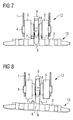
- Fig. 7 shows a view in section of the track roller assembly in accordance with the embodiment of the invention by way of example as illustrated in Fig. 3 to 6 .
- the star-shaped element 6 is mounted on the track roller portion 14 of reduced periphery and on the shaft 4 on which the star-shaped element is mounted freely rotatably.
- the track roller portions 5, 5' can each be freely rotatably mounted, but they can also be screwed or welded together. It will be appreciated however that other mutual fixings for the track roller portions 5, 5' are also possible.
- the track roller portions 5, 5' however could also be integral or made in one piece.
- Fig. 9 to 12 show a further embodiment of the invention by way of example thereof.
- Fig. 9 is a side view of a track roller assembly 12 which co-operates with the crawler chain 13 and which uses an pivotally mounted idle or idling roller 11 as a guide means.
- the idling roller 11 can rotate freely on a shaft and pivots about a shaft 4.
- a spring biases the idling roller 11 against the crawler chain such that the idling roller 11 always is in contact with the rail (inner surface) of the crawler chain 3 .
- the idling roller 11 comprises a pair of rollers 11, 11'.
- the pair of rollers 11, 11' is arranged in front of and to the right and the left of projections 7, 7' of the crawler chain 13.
- Two track roller portions 5, 5' are supported freely rotatably on the shaft 4 and normally roll on the rail (inner surface) of the crawler chain 3 beside the projections 7, 7'.
- the crawler chain 13 is disposed on flat ground so that the track roller assembly is in the correct position, that is to say the projections 7, 7' of the crawler chain 13 are enclosed at their respective outsides by the rollers 11, 11'so that they serve as guides.
- Fig. 11 and 12 show the mode of operation of the embodiment of Fig. 10 when the crawler chain 13 is in an inclined position, for example when the vehicle is used on uneven terrain.
- the idling roller 11 (comprising the rollers 11, 11') is of such a configuration and dimensions that the rollers 11, 11' run outside the projections 7, 7'.
- the track roller assembly 12 upon downward movement of the crawler carrier 1 the track roller assembly 12 will be certain to encounter the chain links 3 in the correct position on the crawler chain 13.
- This arrangement also ensures that the chain cannot be displaced laterally relative to the track roller portions 5, 5'. In that way it is possible to reliably avoid excessive wear and damage to the crawler chain.
Landscapes
- Engineering & Computer Science (AREA)
- Chemical & Material Sciences (AREA)
- Combustion & Propulsion (AREA)
- Transportation (AREA)
- Mechanical Engineering (AREA)
- Jib Cranes (AREA)
- Devices For Conveying Motion By Means Of Endless Flexible Members (AREA)
- Escalators And Moving Walkways (AREA)
Abstract
Description
- The present invention generally concerns a track roller assembly for the crawler chain of a crawler chassis and a crawler chassis for a crawler vehicle, in particular for a crane, which has said track roller assembly.
- Usually crawler chains comprising chain links are guided between two track rollers. If a crane or an excavator with a crawler chassis with a crawler chain is moved on uneven terrain, problems can arise however, particularly in the case of depressions and holes in the ground. If the crane for example is turned on the spot and in that case the crawler chain sags in the centre precisely at the location of the depression in the ground, then the situation can occur where the track roller rides up on to the projection of the crawler chain. The projections of the crawler chain usually serve for guiding the crawler chain between the track rollers.
- The same thing can occur if the crane turns on slightly inclined terrain. In this case also there is the danger of the crawler chain being positioned inclinedly relative to the track roller, whereby the track roller can ride up on to the projection of the crawler chain as the track roller, by way of the projections, entrains the ground-engaging plate of the crawler chain, but that remains on the ground.
- In the situations just discussed above therefore the crawler chain and the track rollers can suffer from damage, although various approaches are already known in this respect for reducing the loadings on the crawler chains and wear thereof.
- Thus for example
DE 100 36 367 A1 describes a crawler chassis which has a crawler carrier and at least one drive tumbler which can be fixed thereto, an idler wheel, an endless chain, a plurality of track rollers arranged at the lower run, and a direction-changing roller mounted in a mounting support. In order to alleviate stress peaks on the endless chain and thus to be able to prolong the service life of the crawler chain or reduce the wear thereof, the direction-changing roller is supported resiliently. That however only resolves the problem of avoiding high loadings on the crawler chain when rigging the crane insofar as a rigid arrangement of the drive tumbler and the idler wheel is used and the stress peaks which occur in that situation are reduced. -
DE 36 03 261 A1 describes a further crawler chassis for bulldozers, loading crawler tractors or the like, wherein the aim is to resolve the problem of maintenance of the mountings of the running gear frame of the crawler chassis. Spherical mountings are used for that purpose, which are intended to reduce shock loadings on the chassis and achieve good damping. However loadings which act directly on the crawler chain are not addressed. - In addition
DE 101 32 903 A1 discloses a crawler chassis for excavators, in particular for large hydraulic excavators, which has a crawler carrier accommodating a crawler chain, at least one chain wheel and at least one idler wheel, between which the crawler chain is guided if required by way of guide elements and over which the crawler chain can be deflected, and at least one tensioning element for the crawler chain. That arrangement is intended to reduce wear of the crawler chain. For that purpose the idler wheel is of a larger diameter than the chain wheel and the crawler chain is guided in the upper run substantially rectilinear between the idler and chain wheels. However, here too no solution is put forward, which would make it possible to avoid damage to the crawler chain and the track wheels if the crawler chassis is used on sloping or uneven terrain so that there is the danger of the track wheels running up on to the projections of the crawler chain. -
JP 09254836 A - In
US 2004/0026996A1 , on which disclosure the preamble ofclaims 1 and 5 is based, andUS 6,726,293 B2 a star carrier roller assembly is disclosed used in certain tracked mobile machines. The shown star carrier roller assembly includes a carrier roller positioned adjacent to a sprocket having a plurality of teeth. The sprocket is attached to the carrier roller to ensure rotation of the carrier roller even if undesirable substances become attached quite often inhibiting rotation of the carrier rollers. Such a stair carrier roller assembly should limit the wear of the carrier roller. - A similar star carrier roller assembly is shown in
DE 296 16 753 U1 andDE 196 40 145 A1 . Both documents merely show an assembly comprising a star carrier roller for carrying the upper part of a crawler chain. In this case, the star carrier roller is fixedly mounted on a shaft for rotating together with the same. - In
US 2,466,068 A a star carrier roller assembly is shown arranged at the upper part of the crawler chain. -
JP 05039065 A - A crawler belt slippage preventing structure is disclosed in
JP 10035549 A -
JP 10119834 A - Finally,
JP 61064588 A - Taking the above into consideration, it is an object of the present invention to provide a track roller assembly for a crawler chain in which it can be avoided that track roller portions run up on to projections on the crawler chain.
- The above object is solved, in accordance with a first aspect of the invention, by a track roller assembly for a crawler chain, the track roller assembly being adapted to be mounted in a crawler carrier. The inventive track roller assembly comprises at least two spaced track roller portions with running surfaces for running on the crawler chain, and a starshaped element for guiding the track roller assembly on the crawler chain. The star-shaped element is mounted freely rotatably between the at least two track roller portions, and provided with a plurality of teeth, wherein the teeth co-operate with the crawler chain in such a way that on rolling over chain links of the crawler chain they engage into corresponding gaps in the crawler chain. The teeth extend beyond the running surfaces of the at least two track roller portions and between projections of the crawler chain such that it is ensured that the crawler chain is not displaced laterally relative to the track roller portions and does not roll up on to the projections of the crawler chain.
- The provision of the star-shaped element provides that it is possible to avoid the track roller portions running up on to the projections on the crawler chain when the chain experiences inclined positioning on uneven terrain or sags over a depression in the ground. The star-shaped element holds the track roller assembly on the correct line in addition to guidance for the track roller portions by the projections of the crawler chain so that when the crawler carrier moves downwardly on to the chain links of the crawler chain the track roller portions remain in the guidance of the projections and cannot run up thereonto. It is possible in that way to avoid excessive wear and also damage to the crawler chain and to the track rollers which can occur as a consequence of such interim situations. The service life of the crawler chain can be prolonged in that way, whereby the operating costs of the excavator or crane which has the track roller assembly according to the invention can also be reduced. Due to the fact that the star-shaped wheel is supported freely rotatably the crawler chain drives the star-shaped element independently from the track roller portions such that even if the track roller portions do not rotate a suitable guidance is ensured.
- It is thus possible, in the case of a crawler chain, to use low projections without the track roller portions being able to run beyond the projections. Low projections afford the advantage that the radius for the transmission of the drive torque from the vehicle transmission to the chain is small, that is to say the forward drive force is high. In addition it is thus also possible for the transmissions, the track rollers and the drive wheels to be produced inexpensively.
- As already mentioned above, in accordance with the invention the star-shaped element is mounted freely rotatably on a shaft. When the crane or the excavator or another vehicle which uses the track roller assembly for a crawler chain of a crawler chassis moves, the crawler carrier with the star-shaped element and the track roller portions moves relative to the chain links of the crawler chain, which rest on the ground. As a result, the star-shaped element experiences a force component by way of one of the chain links of the crawler chain so that the star-shaped element rotates on the shaft which is common to the track roller assemblies.
- The star-shaped element may have the form of for example a star wheel. In accordance with an aspect of the invention the star-shaped element is provided with prongs or teeth which form guide means. The star-shaped element can have five teeth; it is however also possible to provide any other configuration which is suitable for co-operating with corresponding recesses or gaps in the crawler chain.
- In accordance with a further aspect of the invention, the above-mentioned object can be solved by a track roller assembly for a crawler chain, the track roller assembly being adapted to be mounted in a crawler carrier. This track roller assembly comprises at least two spaced track roller portions with running surfaces for running on the crawler chain and an idling roller for guiding the track roller assembly on the crawler chain. The idling roller is mounted in front of the at least two track roller portions and the idling roller is pivotally mounted on a shaft and remains in contact with the crawler chain such that it is ensured that the crawler chain is not displaced laterally relative to the track roller portions and does not roll up on to the projections of the crawler chain. The idling roller afford security and stability in order to guarantee tracking truth with only a slight level of chain play.
- In accordance with a further aspect of the invention the idling roller can rotate freely on the common shaft with the track roller portions. Upon displacement of the crane the crawler carrier with the idling roller and the track roller portions moves relative to the chain links which are resting on the ground. If now the crawler chain is sagging or if a chain link of the crawler chain, for example the base plate, is in an inclined position relative to the track roller portions, the idling roller ensures that the crawler chain is not displaced laterally relative to the track roller portions and does not run up on to the projections.
- In accordance with still a further aspect of the present invention the idling roller is in the form of a pair of rollers which can rotate freely on a front shaft of the track roller portions. The pair of rollers stabilises the track roller portions and gives additional security for ensuring tracking fidelity of the track roller assembly on the crawler chain. In particular, the pair of rollers can rotate freely on a front shaft and can be pivotally arranged on the shaft which extends through the track roller portions. In the situation where the chain sinks, the pair of rollers moves downwardly. In that case, guidance for the chain is still maintained by virtue of the fact that the projections of the chain are still guided between the two rollers of the pair of rollers. In that case the rollers of the first guide means are preferably so arranged that they can carry lateral forces of the chain.
- In accordance with a further aspect of the invention, there is provided a crawler chassis for for example a lattice jib crane. The crawler chassis comprises a crawler carrier, a crawler chain having two rows of projections provided on an inside of the crawler chain, and at least one track roller assembly including at least two track roller portions with running surfaces for running on the crawler chain besides the two rows of projections, and a star-shaped element mounted freely rotatably on a shaft on the crawler carrier of the crawler chassis between the at least two track roller portions. The star-shaped element of the at least one track roller assembly co-operates with the crawler chain to prevent lateral displacement of the crawler chain relative to the track roller assembly such that it is ensured that the crawler chain is not displaced laterally relative to the track roller portions and does not roll up on to the projections of the crawler chain.
- The provision of a crawler chassis which has a track roller assembly as mentioned ' above again makes it possible to ensure that the track roller portions do not roll up on to the projections on the crawler chain when the chain experiences inclined positioning on uneven terrain or sags over a dip in the ground. That accordingly avoids wear of and damage to the crawler chain and the track roller portions.
- In accordance with a further aspect of the invention a crawler chassis comprises a crawler carrier, a crawler chain having at least one row of projections provided on an inside of the crawler chain, at least one track roller assembly including at least two track roller portions with running surfaces for running on the crawler chain besides the at least one row of projections, and an idling roller for guiding the track roller assembly on the crawler chain. The idling roller is pivotally mounted with respect to the track roller portions and is arranged in front of the at least two track roller portions and is remaining in contact with the crawler chain such that it is ensured that the crawler chain is not displaced laterally relative to the track roller portions and does not roll up on to the projections of the crawler chain.
- In a further exemplary embodiment of the present invention, the track roller assembly of the crawler chassis may have at least two track roller portions with running surfaces for running on the crawler chain and at least one track roller portion which is arranged axially between the at least two track roller portions and whose periphery is reduced in relation to the at least two track roller portions.
- In accordance with a further aspect of the present invention the crawler chassis is of such a configuration that the maximal play between the star shaped element or the idling roller and the crawler chain is less than the maximal play between the track roller portions and the crawler chain.
- In a further exemplary embodiment of the present invention, the idling roller has an outer peripheral surface which is formed such that the at least one row of projections of the crawler chain is laterally guided by the idling roller.
- In a further exemplary embodiment of the present invention, two rows of projections are arranged in mutually spaced relationship on the crawler chain and the idling roller of the track roller assembly is in the form of a pair of rollers which can rotate freely on a front shaft and which are arranged with a gap between it. The two rollers are arranged such that the two rows of projections project into the gap between the two rollers.
- In a further exemplary embodiment of the present invention, the at least two track roller portions are freely rotatably mounted on a shaft and the idling roller of the track roller assembly is pivotally mounted on the shaft.
- In accordance with a still further aspect the crawler chassis is equipped with a crawler chain which is in the form of an endless chain.
- It is explicitly stated that all features disclosed in the description and/or the claims are intended to be disclosed separately and independently from each other for the purpose of original disclosure as well as for the purpose of restricting the claimed invention independent of the composition of the features in the embodiments and/or the claims. It is explicitly stated that all value ranges or indications of groups of entities disclose every possible intermediate value or intermediate entity for the purpose of original disclosure as well as for the purpose of restricting the claimed invention, in particular as limits of value ranges.
- Various embodiments of the invention are described hereinafter for further description and for improved understanding with reference to the accompanying drawings in which:
- Fig. 1
- shows a view in section through a known track roller assembly,
- Fig. 2
- shows a view in section through a known track roller assembly,
- Fig. 3
- shows a side view of the track roller assembly in accordance with an embodiment by way of example of the invention,
- Fig. 4
- shows a further side view of the track roller assembly shown in
Fig. 3 , - Fig. 5
- shows a further side view of the track roller assembly shown in
Fig. 3 , - Fig. 6
- shows a further side view of the track roller assembly shown in
Fig. 3 , - Fig. 7
- shows a view in section of the track roller assembly in accordance with an embodiment by way of example of the invention,
- Fig. 8
- shows a further view in section of the track roller assembly of
Fig. 7 , - Fig. 9
- shows a side view of a further embodiment by way of example of the invention,
- Fig. 10
- shows a view in section of the embodiment shown in
Fig. 9 , - Fig. 11
- shows a further side view of the embodiment shown in
Fig. 9 , and - Fig. 12
- shows a further view in section of the embodiment shown in
Fig. 9 . -
Fig. 1 shows a view in section of a knowntrack roller assembly 12. A double track roller or a track roller comprising twotrack roller portions 2, 2' is mounted by way of ashaft 4 on a crawler carrier 1 of the crawler chassis. Thetrack roller assembly 12 rests on acrawler chain 13 which is composed of individual chain links 3. Thecrawler chain 13 also has a pair ofprojections 7 and two rows of projections, respectively which are arranged in mutually spaced relationship on the inside of the chain links 3. The spacing of theprojections 7 is so selected that the projections can serve as a guide for thetrack roller portions 2, 2' so that thetrack roller portions 2, 2' run against the outside of theprojections 7. - In
Fig. 1 thecrawler chain 13 is shown in a condition of lying flat on the ground, with thetrack roller assembly 12 being disposed in its correct position or tracking line with respect to thecrawler chain 13 so that, upon movement of the vehicle with crawler drive such as for example a lattice jib crane (not further shown here) which uses thattrack roller assembly 12 or upon corresponding movement of thetrack roller assembly 12 on thecrawler chain 13, it is not damaged or destroyed. -
Fig. 2 shows the same knowntrack roller assembly 12, but in this case thecrawler chain 13 is in an inclined position, as can be the case for example on uneven terrain. In this situation the track roller portion 2' has rolled up on to theprojection 7 of thecrawler chain 13. In that condition, there can be both damage to thecrawler chain 13 and also to thetrack roller portions 2, 2' of thetrack roller assembly 12. -
Fig. 3 to 6 show a side view of an embodiment by way of example of the invention in a situation involving ongoing movement of thetrack roller assembly 12 relative to thecrawler chain 13. Thetrack roller assembly 12 has twotrack roller portions 5, 5' with running surfaces for running on thecrawler chain 13. A furthertrack roller portion 14 of reduced periphery is arranged axially between the twotrack roller portions 5, 5'. Arranged on thetrack roller portion 14 of reduced periphery and between thetrack roller portions 5, 5' is a star-shapedelement 6 with five teeth 6', 6'', 6''', 6'''', 6'''''. - The star-shaped
element 6 which for example can be in the form of a star wheel can rotate freely on theshaft 4. Upon displacement of a crane with a crawler chassis which has thistrack roller assembly 12, the crawler carrier 1 with the star-shapedelement 6 and thetrack roller portions 5, 5' moves relative to thechain links 3 which are resting on the ground. As a result the star-shapedelement 6 experiences a force component by way of thecentral portion 9 of thecrawler chain 13 and thus rotates on theshaft 4. - The star-shaped
element 6 is of such a configuration that, when rolling over the chain links 3, it repeatedly engages into thegaps 8 in thecrawler chain 13. If the chain now sags, the star-shapedelement 6 ensures that thecrawler chain 13 is not displaced laterally relative to thetrack roller assemblies 5, 5' and does not roll up on to the projections. -
Fig. 7 shows a view in section of the track roller assembly in accordance with the embodiment of the invention by way of example as illustrated inFig. 3 to 6 . The star-shapedelement 6 is mounted on thetrack roller portion 14 of reduced periphery and on theshaft 4 on which the star-shaped element is mounted freely rotatably. Thetrack roller portions 5, 5' can each be freely rotatably mounted, but they can also be screwed or welded together. It will be appreciated however that other mutual fixings for thetrack roller portions 5, 5' are also possible. Thetrack roller portions 5, 5' however could also be integral or made in one piece. - In the condition shown in
Fig. 7 thecrawler chain 13 is resting on a flat surface. A tooth of the star-shaped element engages into agap 8 between thechain links 3 of thecrawler chain 13 and thereby holds thetrack roller assembly 12 exactly in its correct tracking alignment. By virtue of the invention however, as shown inFig. 8 , that is also the case on uneven terrain when thecrawler chain 13 is in an inclined position. When the crawler carrier 1 moves downwardly, the teeth of the star-shaped element again engage into thenext gap 8 and thus prevent thetrack roller portions 5, 5' from running up on to theprojections 7, 7'. In addition the play between the star-shaped element and thecrawler chain 13 is less than the play between thetrack roller portions 5, 5'. -
Fig. 9 to 12 show a further embodiment of the invention by way of example thereof. In this respectFig. 9 is a side view of atrack roller assembly 12 which co-operates with thecrawler chain 13 and which uses an pivotally mounted idle or idlingroller 11 as a guide means. The idlingroller 11 can rotate freely on a shaft and pivots about ashaft 4. A spring biases the idlingroller 11 against the crawler chain such that the idlingroller 11 always is in contact with the rail (inner surface) of thecrawler chain 3 . - It can be seen from
Fig. 10 the idlingroller 11 comprises a pair ofrollers 11, 11'. The pair ofrollers 11, 11' is arranged in front of and to the right and the left ofprojections 7, 7' of thecrawler chain 13. Twotrack roller portions 5, 5' are supported freely rotatably on theshaft 4 and normally roll on the rail (inner surface) of thecrawler chain 3 beside theprojections 7, 7'. - In this case the
crawler chain 13 is disposed on flat ground so that the track roller assembly is in the correct position, that is to say theprojections 7, 7' of thecrawler chain 13 are enclosed at their respective outsides by therollers 11, 11'so that they serve as guides. -
Fig. 11 and 12 show the mode of operation of the embodiment ofFig. 10 when thecrawler chain 13 is in an inclined position, for example when the vehicle is used on uneven terrain. The idling roller 11 (comprising therollers 11, 11') is of such a configuration and dimensions that therollers 11, 11' run outside theprojections 7, 7'. Thus, upon downward movement of the crawler carrier 1 thetrack roller assembly 12 will be certain to encounter thechain links 3 in the correct position on thecrawler chain 13. This arrangement also ensures that the chain cannot be displaced laterally relative to thetrack roller portions 5, 5'. In that way it is possible to reliably avoid excessive wear and damage to the crawler chain. -
- 1
- crawler carrier
- 2, 2'
- track roller portions
- 3
- chain links
- 4
- shaft
- 5, 5'
- track roller portions
- 6
- first guide means
- 6' - 6""'
- teeth
- 7, 7'
- projection
- 8
- gap
- 9, 9'
- projection
- 10
- roller
- 11
- idling rollers
- 12
- track roller assembly
- 13
- crawler chain
- 14
- track roller portion of reduced periphery
Claims (14)
- A track roller assembly for a crawler chain (13), the track roller assembly being adapted to be mounted in a crawler carrier (1), comprising:at least two spaced track roller portions (5, 5') with running surfaces for running on the crawler chain (13)
characterized bya star-shaped element (6) for guiding the track roller assembly (12) on the crawler chain (13), wherein the star-shaped element (6) is mounted freely rotatably between the at least two track roller portions (5, 5'), and wherein the star-shaped element (6) is provided with a plurality of teeth (6', 6", 6"', 6"", 6""'), wherein the teeth (6', 6", 6"', 6"", 6""') co-operate with the crawler chain (13) in such a way that on rolling over chain links (3) of the crawler chain (13) they engage into corresponding gaps (8) in the crawler chain (13) and the teeth (6', 6", 6"', 6"", 6""') extend beyond the running surfaces of the at least two track roller portions (5, 5') and between projections (7, 7') of the crawler chain (13) such that it is ensured that the crawler chain (13) is not displaced laterally relative to the track roller portions (5, 5') and does not roll up on to the projections (7) of the crawler chain (13). - The track roller assembly according to claim 1 wherein at least two spaced track roller portions (5, 5') are mounted freely rotatably on a shaft (4) of the crawler chassis.
- The track roller assembly according to one of the preceding claims wherein the maximal play between the star-shaped element (6, 10) and the crawler chain (13) is less than the maximal play between the track roller portions (5, 5') and the crawler chain (13).
- The track roller assembly according to one of the preceding claims wherein the star-shaped element (6) has five teeth (6', 6", 6"', 6"", 6""').
- A track roller assembly for a crawler chain (13), the track roller assembly being adapted to be mounted in a crawler carrier, comprising:at least two spaced track roller portions (5, 5') with running surfaces for running on the crawler chain (13),
characterized byan idling roller (11) for guiding the track roller assembly (12) on the crawler chain (13), wherein the idling roller (11) is mounted in front of the at least two track roller portions (5, 5'), and the idling roller (11) is pivotally mounted on a shaft (4) and remains in contact with the crawler chain (13) such that it is ensured that the crawler chain (13) is not displaced laterally relative to the track roller portions (5, 5') and does not roll up on to the projections (7) of the crawler chain (13). - The track roller assembly according to claims 5 wherein the idling roller (11) includes a pair of rollers (11), the rollers (11) being mounted freely rotatably on a front shaft of the at least two track roller portions (5, 5').
- A crawler chassis comprising:a crawler carrier (1);a crawler chain (13) having two rows of projections (7, 7') provided on an inside of the crawler chain (13),
characterized byat least one track roller assembly (12) according to one of claims 1-4, wherein the running surfaces run on the crawler chain (13) besides the two rows of projections (7, 7'),wherein the star-shaped element (6) of the at least one track roller assembly (12) co-operates with the crawler chain (13) to prevent lateral displacement of the crawler chain (13) relative to the track roller assembly (12) such that it is ensured that the crawler chain (13) is not displaced laterally relative to the track roller portions (5, 5') and does not roll up on to the projections (7) of the crawler chain (13). - The crawler chassis according to claim 7 wherein the star-shaped element (6) of the track roller assembly (12) is provided with teeth (6', 6", 6"', 6"", 6""'), wherein the teeth (6', 6", 6"', 6"", 6""') of the star-shaped element (6) co-operate with the crawler chain (13) in such a way that on rolling over the chain links (3) they engage into corresponding gaps (8) in the crawler chain (13).
- The crawler chassis according to claim 7 or 8 wherein the star-shaped element (6) has five teeth (6', 6", 6"', 6"", 6"").
- A crawler chassis comprising:a crawler carrier (1);a crawler chain (13) having at least one row of projections (7, 7') provided on an inside of the crawler chain (13),
characterized byat least one track roller assembly (12) according to one of claims 5-6, wherein the running surfaces run on the crawler chain (13) besides the at least one row of projections (7, 7'), and the idling roller (11) guids the track roller assembly (12) on the crawler chain (13), wherein the idling roller (11) is pivotally mounted with respect to the track roller portions (5, 5') and is arranged in front of the at least two track roller portions (5, 5'). - The crawler chassis according to claim 10 wherein the idling roller (11) has an outer peripheral surface, the outer peripheral surface being fomed such tha the at least one row of projections (7, 7') of the crawler chain (13) is laterally guided by the idling roller (11).
- The crawler chassis according to claim 10 or 11 wherein two rows of projections (9) are arranged in mutually spced relationship on the crawler chaibn (13) and the idling roller (11) of the track roller assembly (12) is in the form of a pair of rollers (11, 11') which can rotate freely on a front shaft and which are arranged with a gap between it, wherein the two rollers (11, 11') are arranged such that the two rows of projections (7, 7') project into the gap between the two rollers (11, 11').
- The crawler chassis according to claim 10 wherein the at least two track roller portions (5, 5') are freely rotatably mounted on a shaft (4) and the idling roller (11) of the track roller assembly (12) is pivotally mounted on the shaft (4).
- The crawler chassis according to one of the claims 7 to 13 wherein the crawler chain (13) is an endless chain.
Applications Claiming Priority (2)
| Application Number | Priority Date | Filing Date | Title |
|---|---|---|---|
| US52166304P | 2004-06-15 | 2004-06-15 | |
| PCT/EP2005/006356 WO2005123490A1 (en) | 2004-06-15 | 2005-06-14 | Track roller assembly for the crawler chain of a crawler chassis |
Publications (2)
| Publication Number | Publication Date |
|---|---|
| EP1755937A1 EP1755937A1 (en) | 2007-02-28 |
| EP1755937B1 true EP1755937B1 (en) | 2008-12-10 |
Family
ID=34973014
Family Applications (1)
| Application Number | Title | Priority Date | Filing Date |
|---|---|---|---|
| EP05764220A Active EP1755937B1 (en) | 2004-06-15 | 2005-06-14 | Track roller assembly for the crawler chain of a crawler chassis |
Country Status (7)
| Country | Link |
|---|---|
| US (1) | US7594705B2 (en) |
| EP (1) | EP1755937B1 (en) |
| JP (1) | JP2008502524A (en) |
| CN (1) | CN100457531C (en) |
| AT (1) | ATE416965T1 (en) |
| DE (2) | DE602005011608D1 (en) |
| WO (1) | WO2005123490A1 (en) |
Families Citing this family (14)
| Publication number | Priority date | Publication date | Assignee | Title |
|---|---|---|---|---|
| JP5074113B2 (en) * | 2007-06-28 | 2012-11-14 | 株式会社小松製作所 | Final reduction gear, construction machine equipped with the same, and crawler belt winding method |
| DE102010022304A1 (en) | 2010-06-01 | 2011-12-01 | Veritas Ag | Quick coupling for fluid lines |
| CN102001368A (en) * | 2010-11-02 | 2011-04-06 | 上海三一科技有限公司 | Novel track plate |
| CN103204187A (en) * | 2012-01-11 | 2013-07-17 | 刘育超 | Engineering machine running device |
| USD751609S1 (en) | 2012-06-29 | 2016-03-15 | Caterpillar Inc. | Undercarriage track link for mobile earthmoving machine |
| USD719588S1 (en) | 2012-06-29 | 2014-12-16 | Caterpillar Inc. | Undercarriage track system for mobile earthmoving machine |
| USD712935S1 (en) | 2012-06-29 | 2014-09-09 | Caterpillar Inc. | Undercarriage track shoe for mobile earthmoving machine |
| USD709527S1 (en) | 2012-06-29 | 2014-07-22 | Caterpillar Inc. | Undercarriage track idler for mobile earthmoving machine |
| USD727974S1 (en) | 2012-06-29 | 2015-04-28 | Caterpillar Inc. | Undercarriage track roller for mobile earthmoving machine |
| CN105172921A (en) * | 2015-08-19 | 2015-12-23 | 常熟华威履带有限公司 | Tooth-type structure of support chain wheel of hydraulic excavator and hydraulic excavator |
| US9688325B2 (en) | 2015-08-28 | 2017-06-27 | Caterpillar Inc. | Undercarriage assembly and track links for assembly |
| US10889342B2 (en) * | 2017-05-04 | 2021-01-12 | Caterpillar Inc. | Contoured double pass roller path for a track chain |
| CN108035758B (en) * | 2017-12-07 | 2019-12-31 | 辽宁工程技术大学 | Crawler walking type hydraulic support |
| CN111005726B (en) * | 2019-11-20 | 2021-06-18 | 中国海洋大学 | Tooth-grouted device and method special for mining vehicle capable of adapting to different deep sea surface soil bodies |
Family Cites Families (20)
| Publication number | Priority date | Publication date | Assignee | Title |
|---|---|---|---|---|
| US1725817A (en) * | 1925-02-25 | 1929-08-27 | Harnischfeger Corp | Flexible-tread truck |
| US2113018A (en) * | 1933-02-27 | 1938-04-05 | James Cunningham Son & Company | Vehicle track |
| US2466068A (en) | 1945-04-17 | 1949-04-05 | Nathan G Archer | Roller driving gear |
| US3504951A (en) * | 1968-08-28 | 1970-04-07 | Us Army | Endless track |
| US3776326A (en) * | 1969-12-31 | 1973-12-04 | Blaw Knox Const Equipment | Paving machine |
| US4458955A (en) * | 1982-01-15 | 1984-07-10 | Aai Corporation | Suspension arm for upper and lower track runs |
| JPS6164588A (en) | 1984-09-03 | 1986-04-02 | Yanmar Diesel Engine Co Ltd | Track roller of crawler traveling apparatus |
| DE3603261A1 (en) | 1986-02-03 | 1988-03-10 | Liebherr Werk Telfs Gmbh | Track-laying gear for bulldozers, loading tractors or the like |
| CN2070705U (en) | 1990-04-09 | 1991-02-06 | 陈东坡 | Correcting guided wheel for chain-track tractor |
| JPH0539065A (en) | 1991-08-08 | 1993-02-19 | Bridgestone Corp | Wheel slip-off preventing mechanism for rubber crawler and rolling wheel therefor |
| IL102928A (en) * | 1991-08-26 | 1996-03-31 | Edwards Harper Mcnew & Co | Replacement endless vehicle tracks |
| JPH09254836A (en) | 1996-03-23 | 1997-09-30 | Bridgestone Corp | Rolling wheel for rubber crawler |
| JP3886566B2 (en) | 1996-07-19 | 2007-02-28 | セイレイ工業株式会社 | Crawler-type running section track slip-off prevention structure |
| DE19640145A1 (en) | 1996-09-28 | 1998-04-09 | O & K Mining Gmbh | Support roller for chain driven vehicles, e.g. excavators |
| DE29616953U1 (en) | 1996-09-28 | 1998-01-29 | O & K Mining Gmbh | Support roller for tracked vehicles |
| JPH10119834A (en) | 1996-10-14 | 1998-05-12 | Iseki & Co Ltd | Running crawler guide |
| DE10036367C2 (en) | 2000-07-18 | 2002-09-26 | Atecs Mannesmann Ag | crawler track |
| DE10132903A1 (en) | 2001-07-06 | 2003-01-23 | Terex Germany Gmbh & Co Kg | Caterpillar track for excavators has chain wheel and at least one guide wheel of larger diameter so that chain is guided in straight line between wheels on upper track side |
| US6712549B2 (en) * | 2002-07-09 | 2004-03-30 | Blaw-Knox Construction Equipment Corporation | Double-axis oscillating bogie wheels |
| US6726293B2 (en) | 2002-08-12 | 2004-04-27 | Caterpillar Inc | Tracked mobile machine with star carrier roller and method of assembly |
-
2005
- 2005-06-14 DE DE602005011608T patent/DE602005011608D1/en active Active
- 2005-06-14 WO PCT/EP2005/006356 patent/WO2005123490A1/en not_active Application Discontinuation
- 2005-06-14 EP EP05764220A patent/EP1755937B1/en active Active
- 2005-06-14 JP JP2007515857A patent/JP2008502524A/en active Pending
- 2005-06-14 AT AT05764220T patent/ATE416965T1/en active
- 2005-06-14 CN CNB200580018230XA patent/CN100457531C/en not_active Expired - Fee Related
- 2005-06-14 US US11/629,549 patent/US7594705B2/en active Active
- 2005-06-14 DE DE202005016966U patent/DE202005016966U1/en not_active Expired - Lifetime
Also Published As
| Publication number | Publication date |
|---|---|
| JP2008502524A (en) | 2008-01-31 |
| DE202005016966U1 (en) | 2006-04-20 |
| WO2005123490A1 (en) | 2005-12-29 |
| CN1964884A (en) | 2007-05-16 |
| DE602005011608D1 (en) | 2009-01-22 |
| US20080185911A1 (en) | 2008-08-07 |
| ATE416965T1 (en) | 2008-12-15 |
| CN100457531C (en) | 2009-02-04 |
| EP1755937A1 (en) | 2007-02-28 |
| US7594705B2 (en) | 2009-09-29 |
Similar Documents
| Publication | Publication Date | Title |
|---|---|---|
| EP1755937B1 (en) | Track roller assembly for the crawler chain of a crawler chassis | |
| JP5230836B1 (en) | Track link and track device | |
| US7182414B2 (en) | Undercarriage equipped with non-steel type rubber crawler using chain action | |
| AU2009335970B2 (en) | Idler and undercarriage assembly for track-type machine | |
| US6220378B1 (en) | Drive mechanism for a track type work machine having enhanced durability | |
| WO2007119719A1 (en) | Crawler belt | |
| US20060028066A1 (en) | Tracked travel device | |
| GB2317671A (en) | Cushioned roller for track laying vehicle. | |
| JP4671903B2 (en) | Track roller guard | |
| JP4179444B2 (en) | Tracked vehicle traveling device and downwheel | |
| JP2011088519A (en) | Elastic crawler vehicle | |
| CN211252826U (en) | Thrust wheel of excavator | |
| TWI614167B (en) | Vehicle with track tension adjustment | |
| US7108085B2 (en) | Equalizer bar for a track-type vehicle | |
| JPS5918952Y2 (en) | Track device for tracked vehicles | |
| JP4916359B2 (en) | Elastic crawler | |
| JP2008149899A (en) | Traveling body for track-laying vehicle | |
| JP2001334969A (en) | Crawler type traveling device | |
| KR20010074321A (en) | Exclude steel core track | |
| TWM549726U (en) | Carrier with track tightness adjustment | |
| JP2000142502A (en) | Crawler traveling device | |
| JP2006143161A (en) | Working vehicle | |
| CA2412175A1 (en) | Mid-roller wheels for endless drive track system |
Legal Events
| Date | Code | Title | Description |
|---|---|---|---|
| PUAI | Public reference made under article 153(3) epc to a published international application that has entered the european phase |
Free format text: ORIGINAL CODE: 0009012 |
|
| 17P | Request for examination filed |
Effective date: 20061002 |
|
| AK | Designated contracting states |
Kind code of ref document: A1 Designated state(s): AT BE DE NL |
|
| 17Q | First examination report despatched |
Effective date: 20070730 |
|
| DAX | Request for extension of the european patent (deleted) | ||
| RBV | Designated contracting states (corrected) |
Designated state(s): AT BE DE NL |
|
| RAP1 | Party data changed (applicant data changed or rights of an application transferred) |
Owner name: TEREX DEMAG GMBH |
|
| GRAP | Despatch of communication of intention to grant a patent |
Free format text: ORIGINAL CODE: EPIDOSNIGR1 |
|
| GRAS | Grant fee paid |
Free format text: ORIGINAL CODE: EPIDOSNIGR3 |
|
| GRAA | (expected) grant |
Free format text: ORIGINAL CODE: 0009210 |
|
| AK | Designated contracting states |
Kind code of ref document: B1 Designated state(s): AT BE DE NL |
|
| REF | Corresponds to: |
Ref document number: 602005011608 Country of ref document: DE Date of ref document: 20090122 Kind code of ref document: P |
|
| PLBE | No opposition filed within time limit |
Free format text: ORIGINAL CODE: 0009261 |
|
| STAA | Information on the status of an ep patent application or granted ep patent |
Free format text: STATUS: NO OPPOSITION FILED WITHIN TIME LIMIT |
|
| 26N | No opposition filed |
Effective date: 20090911 |
|
| REG | Reference to a national code |
Ref country code: DE Ref legal event code: R082 Ref document number: 602005011608 Country of ref document: DE Representative=s name: MOSER GOETZE & PARTNER PATENTANWAELTE MBB, DE Ref country code: DE Ref legal event code: R082 Ref document number: 602005011608 Country of ref document: DE Representative=s name: RAU, SCHNECK & HUEBNER PATENTANWAELTE RECHTSAN, DE Ref country code: DE Ref legal event code: R081 Ref document number: 602005011608 Country of ref document: DE Owner name: TEREX GLOBAL GMBH, CH Free format text: FORMER OWNER: TEREX-DEMAG GMBH, 66482 ZWEIBRUECKEN, DE |
|
| REG | Reference to a national code |
Ref country code: NL Ref legal event code: HC Owner name: TEREX CRANES GERMANY GMBH; DE Free format text: DETAILS ASSIGNMENT: CHANGE OF OWNER(S), CHANGE OF OWNER(S) NAME; FORMER OWNER NAME: TEREX DEMAG GMBH Effective date: 20170324 Ref country code: NL Ref legal event code: PD Owner name: TEREX GLOBAL GMBH; CH Free format text: DETAILS ASSIGNMENT: CHANGE OF OWNER(S), ASSIGNMENT; FORMER OWNER NAME: TEREX CRANES GERMANY GMBH Effective date: 20170324 |
|
| REG | Reference to a national code |
Ref country code: DE Ref legal event code: R082 Ref document number: 602005011608 Country of ref document: DE Representative=s name: MOSER GOETZE & PARTNER PATENTANWAELTE MBB, DE |
|
| PGFP | Annual fee paid to national office [announced via postgrant information from national office to epo] |
Ref country code: NL Payment date: 20200625 Year of fee payment: 16 Ref country code: BE Payment date: 20200625 Year of fee payment: 16 |
|
| REG | Reference to a national code |
Ref country code: NL Ref legal event code: MM Effective date: 20210701 |
|
| REG | Reference to a national code |
Ref country code: BE Ref legal event code: MM Effective date: 20210630 |
|
| PG25 | Lapsed in a contracting state [announced via postgrant information from national office to epo] |
Ref country code: NL Free format text: LAPSE BECAUSE OF NON-PAYMENT OF DUE FEES Effective date: 20210701 |
|
| PG25 | Lapsed in a contracting state [announced via postgrant information from national office to epo] |
Ref country code: BE Free format text: LAPSE BECAUSE OF NON-PAYMENT OF DUE FEES Effective date: 20210630 |
|
| P01 | Opt-out of the competence of the unified patent court (upc) registered |
Effective date: 20230530 |
|
| PGFP | Annual fee paid to national office [announced via postgrant information from national office to epo] |
Ref country code: DE Payment date: 20230620 Year of fee payment: 19 |
|
| PGFP | Annual fee paid to national office [announced via postgrant information from national office to epo] |
Ref country code: AT Payment date: 20230621 Year of fee payment: 19 |