EP1755811B1 - Tool holder - Google Patents
Tool holder Download PDFInfo
- Publication number
- EP1755811B1 EP1755811B1 EP05705907A EP05705907A EP1755811B1 EP 1755811 B1 EP1755811 B1 EP 1755811B1 EP 05705907 A EP05705907 A EP 05705907A EP 05705907 A EP05705907 A EP 05705907A EP 1755811 B1 EP1755811 B1 EP 1755811B1
- Authority
- EP
- European Patent Office
- Prior art keywords
- tool holder
- taper
- spindle
- cavity
- contact
- Prior art date
- Legal status (The legal status is an assumption and is not a legal conclusion. Google has not performed a legal analysis and makes no representation as to the accuracy of the status listed.)
- Not-in-force
Links
Images


Classifications
-
- B—PERFORMING OPERATIONS; TRANSPORTING
- B23—MACHINE TOOLS; METAL-WORKING NOT OTHERWISE PROVIDED FOR
- B23Q—DETAILS, COMPONENTS, OR ACCESSORIES FOR MACHINE TOOLS, e.g. ARRANGEMENTS FOR COPYING OR CONTROLLING; MACHINE TOOLS IN GENERAL CHARACTERISED BY THE CONSTRUCTION OF PARTICULAR DETAILS OR COMPONENTS; COMBINATIONS OR ASSOCIATIONS OF METAL-WORKING MACHINES, NOT DIRECTED TO A PARTICULAR RESULT
- B23Q3/00—Devices holding, supporting, or positioning work or tools, of a kind normally removable from the machine
- B23Q3/12—Devices holding, supporting, or positioning work or tools, of a kind normally removable from the machine for securing to a spindle in general
-
- B—PERFORMING OPERATIONS; TRANSPORTING
- B23—MACHINE TOOLS; METAL-WORKING NOT OTHERWISE PROVIDED FOR
- B23B—TURNING; BORING
- B23B31/00—Chucks; Expansion mandrels; Adaptations thereof for remote control
- B23B31/006—Conical shanks of tools
-
- B—PERFORMING OPERATIONS; TRANSPORTING
- B23—MACHINE TOOLS; METAL-WORKING NOT OTHERWISE PROVIDED FOR
- B23C—MILLING
- B23C1/00—Milling machines not designed for particular work or special operations
-
- B—PERFORMING OPERATIONS; TRANSPORTING
- B23—MACHINE TOOLS; METAL-WORKING NOT OTHERWISE PROVIDED FOR
- B23B—TURNING; BORING
- B23B2231/00—Details of chucks, toolholder shanks or tool shanks
- B23B2231/02—Features of shanks of tools not relating to the operation performed by the tool
- B23B2231/026—Grooves
- B23B2231/0272—Grooves on conical clamping surfaces
-
- B—PERFORMING OPERATIONS; TRANSPORTING
- B23—MACHINE TOOLS; METAL-WORKING NOT OTHERWISE PROVIDED FOR
- B23B—TURNING; BORING
- B23B2231/00—Details of chucks, toolholder shanks or tool shanks
- B23B2231/22—Compensating chucks, i.e. with means for the compensation of irregularities of form or position
-
- Y—GENERAL TAGGING OF NEW TECHNOLOGICAL DEVELOPMENTS; GENERAL TAGGING OF CROSS-SECTIONAL TECHNOLOGIES SPANNING OVER SEVERAL SECTIONS OF THE IPC; TECHNICAL SUBJECTS COVERED BY FORMER USPC CROSS-REFERENCE ART COLLECTIONS [XRACs] AND DIGESTS
- Y10—TECHNICAL SUBJECTS COVERED BY FORMER USPC
- Y10T—TECHNICAL SUBJECTS COVERED BY FORMER US CLASSIFICATION
- Y10T408/00—Cutting by use of rotating axially moving tool
- Y10T408/94—Tool-support
- Y10T408/95—Tool-support with tool-retaining means
- Y10T408/957—Tool adapter
-
- Y—GENERAL TAGGING OF NEW TECHNOLOGICAL DEVELOPMENTS; GENERAL TAGGING OF CROSS-SECTIONAL TECHNOLOGIES SPANNING OVER SEVERAL SECTIONS OF THE IPC; TECHNICAL SUBJECTS COVERED BY FORMER USPC CROSS-REFERENCE ART COLLECTIONS [XRACs] AND DIGESTS
- Y10—TECHNICAL SUBJECTS COVERED BY FORMER USPC
- Y10T—TECHNICAL SUBJECTS COVERED BY FORMER US CLASSIFICATION
- Y10T409/00—Gear cutting, milling, or planing
- Y10T409/30—Milling
- Y10T409/30952—Milling with cutter holder
Definitions
- the invention relates to a tool holder, and more particularly, a rotary tool holder for releasably holding rotary tool holders for precise cutting or grinding operations.
- Steep taper tool holders have a male tapered portion extending from a V-flange portion.
- the V-flange portion has a V-shaped groove to assist the machine tool changer mechanism in gripping the tool.
- CV tool holders are one of several standards for very similar tool holder designs, all of which have 7/24 tapers (7 inches of diameter change per 24 inches of length.)
- Another common 7/24 tapered tool holder standard is the "BT" tool holder.
- the tapered shank portion of the steep taper tool holder is held in a corresponding female tapered portion of a spindle.
- the tool holder is held in and rotated at high speeds by the spindle.
- the face-taper contact type tool holder can require a specially designed spindle, wherein the mating face of the spindle is machined more precisely to facilitate operating in contact with the face of the tool holder V-flange portion.
- the diametrical increase is typically not uniform along the length of the spindle taper, but is greatest at the front of the taper.
- the spindle taper angle changes, and the tapered surface can even become convex. If the spindle taper were to expand uniformly (maintain the same taper angle), then good fit between spindle and tool holder could be maintained at high speeds via the tool moving axially into the spindle. Unfortunately, because the spindle taper angle changes, the fit between tool holder and spindle degrades at high speeds. The result is two-fold for the standard tool holder.
- Another prior art type face-taper contact tool holder uses a tapered sleeve on a shank which moves axially as the rotational speed increases so that the tool holder stays in contact with the spindle.
- the moveable sleeve can ease tolerancing requirements, but as the tool holder is rotated at high speeds the sleeve moves axially to stay in contact with the spindle.
- the sleeve also increases in diameter due to the centrifugal forces. Therefore, even though the sleeve maintains contact with the spindle, the sleeve can lose contact with the tool holder shank, resulting in a radial gap, thus resulting in unbalance and loss of accuracy.
- Another prior art type face-taper contact tool holder uses a sleeve which is split such that it can flex circumferentially and therefore change diameter.
- the sleeve can thus stay in simultaneous contact with the tool holder shank and the spindle taper as the spindle taper diameter in changing.
- the sleeve still cannot adapt to the changing taper angle, such that contact is still localized at either the front or rear of the taper.
- the split sleeve can also be prone to contamination problems since any material that is present between the sleeve and the tool holder shank will reduce the design's effectiveness, and sealing can be impractical.
- the prior art face-taper contact tool holders can provide an improvement over the standard tool holder, but they can also have varying limitations at high speeds, increased in mechanical complexity, and all require face contact.
- JP 07299614 A discloses a tool holder for retaining a rotary tool in a tapered bore of a spindle.
- the tool holder comprises a shank having a tapered outer surface to match the surface of the tapered bore and a flange adjacent a front end portion of the shank.
- the shank has an opening into which a pulling lever is inserted, which has tapered surfaces.
- the tapered surfaces cooperate with locking balls which are pressed against tapered surfaces on the inner surface of the shank.
- the invention provides a rotary tool holder for detachably retaining a rotary tool in a tapered bore of a spindle, the rotary tool holder comprising: a shank having a tapered outer surface corresponding to the tapered bore, the shank having a front contact portion and a rear contact portion; a flange adjacent the front contact portion; a circular cantilever adjacent one of the front and rear contact portions, the circular cantilever having a fixed end and a free end; a cavity formed in a rear face of the shank, the cavity having an exterior surface forming at least part of the circular cantilever; a pull stud having a first end captured in the cavity and a second end external of the cavity, the second end adapted to have tension applied thereto after the rotary tool holder is positioned in the spindle; pull stud having a distal end with a shape which is complimentary to the shape of the cavity, with a taper of the interior surface of the cavity corresponding to the taper on the distal end of the pull
- a circular cantilever is created by a cavity formed in the rear face of the shank, wherein the exterior surface of the cavity forms at least part of the circular cantilever.
- a pull stud has a first end captured in the cavity and a second end external thereof, wherein the second end is that to which tension is applied in order to draw the tool holder into the bore of the spindle. Tension on the second end of the pull stud causes the first end to apply an outward radial force on the cavity, which urges the exterior surface, i.e., the circular cantilever, in a radially outward direction toward the tapered bore.
- the cavity has an interior surface which tapers from a wider bottom region to a narrower region near the opening thereof, forming a bottle neck.
- the first end of the pull stud tapers from a larger distal portion captured in the wider region of the cavity to a narrower neck which extends through the narrower region of the cavity.
- the second end of the pull stud acts to draw the larger distal portion from the cavity which urges the narrower region of the cavity radially outward.
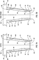
- FIGS. 1a and 1b are diagrammatic representations of a prior art taper only contact, standard steep taper tool holder.
- FIGS. 2a and 2b are diagrammatic representations of a prior art face-taper contact steep taper tool holder.
- FIGS. 3a and 3b are diagrammatic representations of a second prior art face-taper contact steep taper tool holder.
- FIGS. 4a and 4b are diagrammatic representations of a third prior art face-taper contact steep taper tool holder.
- FIG. 5 illustrates an embodiment of a steep taper tool holder not covered by the invention.
- FIGS. 6a and 6b illustrate another embodiment of a steep taper tool holder not covered by the invention.
- FIGS. 7a and 7b illustrate a further embodiment of a steep taper tool holder not covered by the invention.
- FIG. 8 illustrates a further embodiment of a steep taper tool holder not covered by the invention.
- FIGS. 9a and 9b illustrate an embodiment of a steep taper tool holder according to the invention.
- FIG. 10 provides dimensional information for a prior art standard tool holder.
- FIG. 11 is a cross section of an embodiment not covered by the invention.
- FIGS. 12a and 12b illustrate a further embodiment of a steep taper tool holder not covered by the invention.
- FIG. 13 illustrates changing taper angles of a conventional steep taper tool holder compared to those as shown in FIGS. 12a and 12b .
- FIGS. 1a through 4b prior art steep taper tool holders are illustrated in FIGS. 1a through 4b .
- the standard, taper contact only, steep taper tool holder 20 ( FIGS. 1a and 1b ) has a male tapered portion 22 extending from a V-flange portion 24.
- the tapered portion 22 is held in a corresponding female tapered portion 26 of a spindle 28.
- the tool holder 20 is held in the spindle 28 by a pull stud (see FIG. 5 ) and rotated at high speeds by a motor (not shown) which drives the spindle 28.
- the standard steep taper tool holder suffers from certain disadvantages.
- FIG. 1a wherein the tool holder is at rest, the tool holder taper contacts the spindle taper at a front contact region, commonly referred to as the "front gauge line.” This occurs because of the taper tolerances for tool holder taper and the spindle taper.
- FIG. 1b When the tool holder 20 is rotated at high speed, illustrated in FIG. 1b , this divergence of taper angles can produce 'rocking' of the tool holder 20 with resulting loss of accuracy and balance.
- both the spindle taper diameter and the tool holder taper diameter increase under the influence of centrifugal force.
- the spindle taper diameter increases faster than the tool holder taper diameter.
- the diametrical increase is typically not uniform along the length of the spindle taper, but is greatest at the front of the taper. Consequently, the spindle taper angle changes, and the tapered surface can even become convex. The result is two-fold for the standard tool holder 20.
- the tool holder 20 is drawn into to the spindle 28 (moves axially), as can be seen in the difference between dimension A in FIG. 1a and dimension B in FIG. 1b .
- the primary contact which is initially at the front of the taper, i.e., the front gauge line, shifts to the middle or rear of the taper, which results in increased rocking of the tool holder 20 in the spindle 28.
- FIGS. 2a and 2b Some specific examples of prior art face-taper contact steep taper tool holders are the Daishowa Seiki Big-PlusTM, Showa D-F-CTM, and Nikken 3LockTM.
- the Big-PlusTM tool holder 33 shown only generally in FIGS. 2a and 2b , is made to very tight dimensional tolerances such that simultaneous face and taper contact is produced- but there is only minimal interference between the tapers due to high component stiffness and the relatively low retention force.
- the taper contact is still primarily at the front gauge line, due to tolerancing of the respective tapers. Because of the face contact, 'rocking' is greatly reduced for the tool holder 33 when at rest.
- the spindle taper diameter once again increases faster than the tool holder taper diameter, as shown in FIG. 2b . Because the tool holder 33 can not be drawn into the spindle 28 due to the face contact, a radial gap is produced between the tapers. This gap allows radial motion of the tool holder 33, resulting in loss of accuracy and balance. However, axial positioning is maintained by the face contact
- the Showa D-F-CTM steep taper tool holder 36 has a spring-loaded tapered sleeve 38 on a cylindrical shank 40, combined with face contact.
- the intended purpose of the sleeve 38 is to move axially as the rotational speed increases so that the tool holder 33 stays in contact with the spindle 28.
- the use of the moveable sleeve 38 also eases the tolerancing requirements that are more critical on the Big-PlusTM tool holder. At rest, the main contact is still at the front gauge line, as shown in FIG. 3a .
- the sleeve 38 moves axially to stay in contact with the spindle 28, as shown in FIG. 3b .
- the sleeve 38 also increases in diameter due to the centrifugal forces. Therefore, even though the sleeve 38 maintains contact with the spindle 28, the sleeve 38 can lose contact with the tool holder shank 40, resulting in a radial gap.
- the situation is similar to the Big-PlusTM tool holder in that the tool holder 33 can move radially, producing unbalance and loss of accuracy.
- the Nikken 3LockTM tool holder 43 is similar to the D-F-CTM tool holder 33, except the sleeve 46 is split such that it can flex circumferentially and therefore change diameter.
- the flexible sleeve 46 overcomes one limitation of the D-F-CTM tool holder, since the sleeve 46 can now stay in simultaneous contact with the tool holder shank 48 and the spindle taper as the spindle taper diameter is changing. However, the sleeve 46 still cannot adapt to the changing taper angle, such that contact is still localized at either the front or rear of the taper, as shown in FIG. 4b .
- the presence of friction limits the ability of the sleeve 46 to always maintain solid contact between tool holder 43 and taper- some 'slop' is bound to exist, reducing tool holder stiffness.
- the split sleeve 46 can also be prone to contamination problems since any material that is present between the sleeve 46 and the tool holder shank 48 will reduce the design's effectiveness, and sealing the design can be impractical.
- a rotary, steep taper tool holder 50 for detachably retaining a rotary tool in the tapered bore 53 of a spindle 55.
- the rotary tool holder 50 comprises a shank 58 having a front contact portion 60, a rear contact portion 62 and a tapered outer surface 64 which corresponds to the tapered bore 53 of the spindle.
- the tool holder 50 also has the usual flange member 66 adjacent the front contact portion 60 thereof, and the front contact portion 60 of the tapered shank 58 is designed to provide contact with the tapered bore 53 of the spindle 55, such that no face contact is intended.
- a single circular cantilever 70 can be provided on the shank 58 adjacent to either the front 60 or rear 62 contact portions thereof.
- the circular cantilever 70 is provided adjacent the rear contact portion 62 of the shank, as shown in FIG. 5-6a .
- the circular cantilever has a fixed end 73 and a free end 76, which is designed to move radially outward under the influence of centrifugal force when the tool holder 50 is rotated in the spindle 55.
- the tool holder 50 adjusts to taper angle mismatches and changing taper angles at elevated speeds.
- the tool holder 50 does move axially, hard contact is maintained at both the front and rear of the taper under all operating conditions. This two location contact eliminates rocking and radial motion of the tool holder 50 and thus eliminates the associated accuracy and balance problems.
- the tapered outer surface 64 of the shank 58 is provided with an annular recessed region 80 intermediate the front 60 and rear 62 contact portions.
- the tapered shank 58 fits up to the tapered bore 53 such that there is contact only at the front 60 and rear 62 contact areas.
- the rear contact region 62 on the shank 58 is unsupported, in other words, it is on the free end 76 of the circular cantilever 70. Therefore, the amount of deformation and flexibility at the contact region 62 can be adjusted by controlling the length and thickness of the free end 76 of the cantilever 70.
- the annular recessed region 80 also permits the free end 76 of the circular cantilever 70 to move radially without stressing or deforming the outer surface of the tapered shank 58.
- the annular recess 80 also facilitates manufacture of the tapered outer surface of the shank 58 to the proper tolerances to achieve a good fit in the tapered bore 53 of the spindle 55.
- the tapered shank 58 of the tool holder 50 can be comprised of an inner member 83 and a sleeve member 85 disposed over the inner member 83.
- the outer surface of the sleeve member 85 comprises the tapered outer surface 64 of the shank 58.
- the sleeve member 85 also has a first end, and a first portion thereof which forms the circular cantilever 70 at the rear contact portion 62 of the shank 58.
- the circular cantilever 70 is essentially a portion of the first end of the sleeve member 85 which extends axially over the inner member 83 adjacent the rear contact portion 62, but with a narrow gap 88 provided therebetween.
- the inner member 83 is formed with an outside mating surface having a tapered portion 90 and a generally cylindrical portion 93 adjacent the free end 76 of the circular cantilever 70.
- the sleeve 85 has an inside mating surface which has a tapered portion 96 corresponding to the tapered portion 90 of the outside mating surface of the inner member 83.
- the portion of the sleeve member 85 which forms the circular cantilever 70, and more particularly, the free end 76 thereof, is spaced apart from the generally cylindrical portion 93 of the outside mating surface, thus providing the aforesaid gap 88 therebetween.
- the gap 88 between the free end 76 of the circular cantilever 70 and the inner member 83 permits the free end 76 to be partially compressed radially inward, toward the inner member 83, when the tool holder 50 is disposed and retained in the tapered bore 53 of the spindle 55.
- the tool holder 50 is drawn tight into the tapered bore 53 by applying tension to the pull stud 59 (shown in FIG. 5 ) prior to rotation of the tool holder 50.
- there is about 5000 or 6000 pounds of axial force which will pull the tool holder 50 into the spindle 55, via the pull stud 59, which will reduce the diameter of the circular cantilever 70.
- the free end 76 of the circular cantilever 70 will thus be forced radially inward, which will store elastic energy in the cantilever 70. Then, when the tool holder 50 is rotated at high speeds and the spindle bore 53 opens in diameter radially, the free end 76 will return toward the unloaded position, i.e., expand radially outward, and while doing so will stay in contact with the spindle bore 53. This improves the design of the circular cantilever 70, because it reduces the range of outward radial flex which would otherwise be required by the free end 76.
- the sleeve member 85 can be press, or shrink, fitted onto the inner member 83.
- the undercut sections, i.e., free end 76, of the circular cantilever 70 of the sleeve 85 by the inherent (but controllable) flexibility, permit taper contact at selected locations (in this case the rear contact portion 62), and do so with reasonable manufacturing tolerances. Further, because the flexibility of the free end 76 allows sizable radial deformation, the design is suitable for high speed operation without loss of radial accuracy.
- the circular cantilever 70 can compensate for differences in taper angles between the spindle 55 and the tool holder 50. It can also compensate for differences in radial expansion rates between spindle bore 53 and the shank 58 of the tool holder 50, including different expansion rates at the front and rear of the tapers.
- FIGS. 7a and 7b another tool holder 100 is illustrated.
- This tool holder 100 is similar to the tool holder 50 described above, except that a second circular cantilever 103 is provided at the front contact portion 60 of the shank 58.
- This embodiment of the tool holder 100 is also different in that face contact between the V-flange 66 and the face 56 of the spindle 55 is designed to occur. Thus, axial movement of the tool holder 100 into the bore 53 of the spindle 55 is prevented.
- the second circular cantilever 103 likewise having a free end 106 and a fixed end 109, is provided at the front contact portion 60 of the shank 58.
- the free end 106 is located adjacent the front contact portion 60 and extends toward the flange 66.
- rotation of the tool holder 100 in the spindle 55 results in the free ends 76 and 106 of each of the first 70 and second 103 circular cantilevers expanding radially under the influence of centrifugal force such that the free ends 76 and 106 maintain contact with the tapered bore 53 as the tapered bore 53 also expands under the influence of centrifugal force.
- the circular cantilever 103 at the front contact portion 60 is employed to allow the front contact portion 60 of the tool holder 100 to maintain contact with the tapered bore 53 of the spindle 55 during rotation.
- the tool holder 100 thus eliminates all of the sources of error described previously.
- the tool holder 100 will not have tool rocking, radial motion, or axial motion.
- the tool holder 100 does require face contact with the spindle 55, and therefore is not directly interchangeable with all current tools and machines. Nevertheless, it is relatively easy to modify current spindles to accept face contact, and the modified spindles would still be compatible with conventional, non-face contact tools.
- the shank 58 of the dual circular cantilever tool holder 100 is comprised of an inner member 113 and an outer sleeve member 115 disposed over the inner member 113.
- This sleeve member 115 can be like the sleeve member 85 described in connection with the single circular cantilever tool holder 50, including the tapered outer surface and the first circular cantilever 70 at the first end thereof adjacent the rear contact portion 62 of the shank 58.
- this sleeve member 115 further includes the second circular cantilever 103, which is formed by a second portion of the sleeve member, at a second end thereof which is adjacent the front contact portion 60 of the shank 58.
- the free end 106 of the second circular cantilever 103 extends adjacent the front contact portion 60 of the shank 58, toward the flange 66, with a gap 120 between the free end 106 and the inner member 113 of the shank.
- the inner member 113 has a generally cylindrical portion 93 near the rear contact portion 62 and a tapered portion 90. However, the inner member 113 further has a second generally cylindrical portion 123 adjacent the front contact portion 60, such that the tapered portion 90 is intermediate the two generally cylindrical portions 123, 93 adjacent the front 60 and rear 62 contact portions.
- the sleeve member 115 is formed with the inside mating surface 96 which has a tapered portion corresponding to the tapered portion of the outside mating surface 90 of the inner member 113.
- the first and second portions of the sleeve member 115 which form the circular cantilevers 70, 103, and more particularly the free ends 76, 106 thereof, are spaced apart from the generally cylindrical portions 93, 123 of the inner member 113 such that there are gaps 88, 120 between each free end 76, 106 and the adjacent generally cylindrical portions 93, 123.
- the gaps 88, 120 are provided for the same reasons described previously in connection with the single circular cantilever tool holder 50.
- the free end 76 of the first circular cantilever 70 expands to maintain contact with the tapered bore 53 at the rear contact region 62
- the free end 106 of the second circular cantilever 103 expands to maintain contact with the tapered bore 53 at the front contact region 60
- the face contact between the flange 66 and the spindle face 56 prevents the tool holder 100 from being drawn axially into the spindle 55.
- the tapered outer surface of the sleeve member 115 has the annular recessed region 80 which is located intermediate the two circular cantilevers 70, 103, which is provided for the same reasons described previously.
- the shank 203 is comprised of a stepped inner member 206 and a sleeve member 209 disposed thereover.
- the inner member 206 has a stepped outer surface 212, formed from a plurality of generally cylindrical portions 214, 215, 216, and 217, each of which has an increasingly larger diameter from a smaller diameter at the rear portion 210 of the shank 203 to a larger diameter at the front portion 211 thereof.
- the sleeve member 209 has a complimentarily shaped stepped bore 220, i.e., formed from a plurality of generally cylindrical regions 222, 223, and 224, each of which increases in diameter from a smaller diameter at the rear portion 210 of the shank 203 to a larger diameter at the front portion 211 thereof.
- Two of the plurality of generally cylindrical regions, namely regions 223 and 224 of the sleeve member 209 mate with two of the generally cylindrical portions, namely portions 215 and 216, of the inner member 206.
- the cylindrical regions 223 and 224 and cylindrical portions 215 and 216 may only partially overlap when the sleeve member 209 is disposed over the inner member 206, such as, for example, by press fitting.
- the inner member 203 has four generally cylindrical portions 214-217, and the sleeve member 209 has three generally cylindrical regions 222-224.
- FIGS. 9a and 9b illustrate an embodiment of a tool holder 250 according to the invention wherein the tool holder 250 has a tapered shank 253 and a single circular cantilever 256 adjacent the rear contact portion 259 of the shank 253, similarly to the single cantilever tool holder 50 shown in FIGS 5-6b .
- this embodiment of the tool holder 250 has a cavity 260 formed in a rear face 263 of the shank 253, in which the side wall of the cavity, particularly the exterior surface thereof, forms the circular cantilever 256 at the rear contact surface 259.
- the circular cantilever 256 in this embodiment of the tool holder 250 extends toward rear face 263 of the shank 253.
- the shank 253 of this tool holder 250 is not comprised of an inner member and an outer sleeve having end portions which form the one or more circular cantilevers.
- the circular cantilever 256 of this tool holder 250 is formed by creating the cavity 260 in the rear face 263 of the shank 253 such that the side wall of the cavity 260 becomes the circular cantilever 256 wherein the fixed end 267 is adjacent the bottom 261 of the cavity 260 and the free end 270 is at the opening of the cavity 262.
- the tool holder 250 employs a multi-piece wedge-locking system to produce contact of the circular cantilever 256 on the rear of the tapered shank 253 with the bore 53 of the spindle 55.
- the free end 270 of the circular cantilever 256 is forced into contact with the spindle bore 53 via the wedge locking action after the tool holder 250 is pulled into the spindle bore 53.
- the wedge lock and circular cantilever 256 combination allow the shank 253 to stay in contact with the spindle bore 53 in spite of taper angle errors and taper dimensional changes during operation.
- the pull stud 59 has a threaded shaft portion which is received in a threaded bore in the shank, for example as illustrated in FIG. 5 .
- tension on the pull stud 59 will not result in any significant outward radial force on the rear contact surface 62 of the shank 58.
- the cavity 260 formed in the rear face 263 of the shank 253 is specifically configured to capture a specially configured distal end 273 of a pull stud 275, such that tension applied to the pull stud 275 results in creating an outward radial force on the side wall of the cavity 260, and thus the free end 270 of the circular cantilever 256.
- the cavity 260 has an interior side wall surface which tapers from a wider region at the bottom 261 of the cavity 260 to a narrower region near the opening 262 of the cavity 260, forming a bottle neck.
- the distal end 273 of the pull stud 275 captured in the cavity 260 has complimentary shape, having a wider end portion which tapers to a narrower shaft 277 which extends through the opening 262 of the cavity 260.
- the taper of the interior surface of the cavity 270 corresponds to the taper on the distal end 273 pull stud 275.
- Tension applied to the pull stud 275 tries to draw the wider distal end 273 out from the cavity 260 because the front 258 and rear 259 contact surfaces of the shank 253 prevents the tool holder 250 from moving axially into the bore 53 of the spindle 55.
- the corresponding tapers of the inside of the cavity 260 and the distal end 273 of the pull stud 275 captured in the cavity 260 cooperate such that, in order for the wider distal end 273 of the pull stud 275 to be removed from the cavity 260, the side wall of the cavity 260, which is the free end 270 of the circular cantilever 256, must expand outward radially. Consequently, tension on the pull stud 275 further activates the outward radial expansion of the circular cantilever 256, urging it into contact with the tapered bore 53 of the spindle 55.
- the tool holder 250 thus provides the same type of advantages as the previously described single cantilever tool holder 100 illustrated in FIGS. 5-6b .
- the circular cantilever 256 and specifically the free end 270 thereof will expand radially outward along with the outwardly expanding tapered bore 53, such that the free end 270 maintains contact with the rear part of the tapered bore 53. Since there is also no face contact with this tool holder 250, as the tapered bore 53 enlarges radially adjacent the front contact area 258, the tool holder 250 will be drawn axially into the tapered bore 53. Thus, hard contact is also maintained adjacent the front contact region 58 of the tapered bore.
- the tool holder 250 likewise adjusts to taper angle mismatches and changing taper angles at elevated speeds. Therefore, although the tool holder 250 does move axially, hard contact is maintained at both the front 258 and rear 259 contact portions under all operating conditions. Consequently, rocking and radial motion of the tool holder 250 is eliminated, along with the attendant accuracy and balance problems.
- the circular cantilever 256 could alternatively be a split ring with multiple radial slots to add flexibility.
- the design of the pull stud can assume various configurations to complement the design of the split ring.
- the cantilever 256 can be dimensioned such that hard contact between the free end 270 and the spindle bore 53 does not occur until after the tool holder 250 is axially seated. If not, the wedge locking action could preclude further axial motion of the tool holder 250 into the spindle 55.
- One advantage of this design is lower tool holder 250 release forces because the circular cantilever 256 will not be in contact with the spindle bore 53 after the tool holder locking force, i.e., tension on the pull stud 275, is released.
- this embodiment of the tool holder 250 has an annular recessed region 280 in the tapered outer surface of the shank 253 intermediate the front 258 and rear 259 contact portions.
- the annular recessed region 280 is provided for the same reasons described previously with regard to the annular recessed region 80 of the tool holders 50 and 100. It will be appreciated that it is not necessary to include the annular recess region 280 on all embodiments of the tool.
- FIGS. 10 shows dimensional details of a prior art contact only steep taper tool holder 295.
- the standard steep taper tool holder has a 2.750 inch major taper diameter (front contact area) and a 4.00 inch taper length. With the typical 7/24 taper (16 deg 35 min 40 sec) angle, this translates to a 1.583 inch minor diameter (rear contact area).
- the taper half angle (8 deg 17 min 50 sec) is shown.
- the 16 deg 35 min 40 sec angle is the "basic" angle dimension for a 7/24 taper angle. In other words, the male tool holder taper has a "plus” tolerance from this basic angle and the female spindle has a "minus" tolerance from this basic angle.
- the amount of each tolerance is a function of the "class of fit" for the taper.
- a typical tool holder is an "AT3" tolerance which is 16 deg 35 min 40 sec / 16 deg 35 min 46 sec.
- a typical spindle is an "AT2" tolerance which is 16 deg 35 min 36 sec / 16 deg 35 min 40 sec.
- FIG. 11 is a cross section view of a sleeve member 300 for a tool holder having two circular cantilevers 302, 304, one adjacent each of the front 306 and rear 308 contact portions of the shank (not shown).
- the sleeve member 300 can be the same as the sleeve members 85 and 115 for the tool holders 50 and 100 described in connection with FIGS. 7a-7b .
- the sleeve member 300 can particularly be like the sleeve 115 of the tool holder 100, wherein the inner member 113 has a taper mating surface 90 intermediate a pair of generally cylindrical portions 93 and 123 adjacent front 60 and rear 62 contact portions of the shank 58, and specifically, the free ends 76, 106 of the two circular cantilevers 73, 103 on the ends of the sleeve member 115.
- the sleeve 300 outer surface 310 has the aforesaid 7/24 taper, shown as the half angle ⁇ (8 deg 17 min 50 sec), and an inside mating surface has a taper, also shown as a half angle ⁇ , which is 1 deg 30 min 0 sec.
- the outside mating surface of the inner member (not shown) will have the same taper as the inside mating surface 312 of the sleeve 300, i.e., 1 deg 30 min 0 sec.
- the annular recessed region 314 is provided between the circular cantilevers 302, 304, and has a depth ⁇ of about 0.020 inch.
- the outside diameter d fo of the free end 322 of the circular cantilever 302 can be about 2.750 inches
- the inside diameter (which corresponds to the diameter d bf of the sleeve 300 at the front portion of the generally cylindrical front portion of the inner member) can be about 1.650 inches
- the inside diameter d fi of the free end 322 of the circular cantilever 306 can be about 2.460 inches.
- the difference between d fi and d Bf defines a gap g f between the free end 322 and the generally cylindrical portion of the inner member of about 0.405 inch adjacent the front contact portion 306.
- the outside diameter d ro of the free end 321 of the circular cantilever 304 can be about 1.659 inches
- the inside diameter d br of the sleeve 300 at the rear portion (which corresponds to the diameter of the generally cylindrical rear portion of the inner member) can be slightly less than 1.650 inches (accounting for the taper angle B)
- the inside diameter d ri of the free end 321 of the circular cantilever 304 can be about 1.556 inches. This defines a gap between the free end and the inner member and the generally cylindrical rear portion of the inner member of slightly less than 0.0515 inch adjacent the rear contact portion 308.
- the portion of the free end 322 of the circular cantilever 302 which forms the front contact surface 306 adjacent the tapered bore of the spindle can have a length 1 fc of about 0.460 inch and the portion of the free end 321 of the circular cantilever 304 which forms the rear contact surface 308 adjacent the tapered bore of the spindle can have a length 1 rc of about 0.380 inch.
- the total length 1 f of the free end 322 at the front circular cantilever 302 can be about 0.580 inch, whereas the total length 1 r of the free end 321 at the rear circular cantilever 304 can be about 0.747 inch.
- the overall length 1 o of the sleeve member 300 can be about 3.740 inches, and the overall length of the inner member (not shown) would typically be about 4.0 inches.
- the dimensions described above for the circular cantilever 304 adjacent the rear contact portion 308 can be the same for the circular cantilevers adjacent the rear contact portions of the single cantilever tool holders 50, 100 shown in FIGS. 5-6b and 9a-9b .
- Tool holders as described herein can reduce manufacturing costs of standard taper (non-face contact) tool holders.
- a preheat treated steel can be used for the inner member of the tool holder shank, eliminating the need for heat treatment after machining of the body details.
- the sleeve member can be machined and heat treated prior to assembly. Finish grinding of the taper would occur after assembly. This approach would reduce cycle time significantly by eliminating the need for heat treating after machining of the 'front end' of the tool holder.
- An improved fit for standard (non-face contact) tools can be achieved using the single circular cantilever tool holder, e.g., having a sleeve member with circular cantilever only at the rear portion of the shank.
- the hard taper contact at the front portion would assure proper tool axial positioning while the flexible circular cantilever rear contact portion would compensate for taper tolerance mismatches, eliminating "wobble" in the system.
- This design would eliminate the current multiple classes of taper accuracy for standard tapered tool holders because the tool holder with the rear circular cantilever can accommodate the taper angle differences between the shank and the spindle.
- circular cantilever tool holders according to the invention can improve the fit-up, and therefore the balance, accuracy, and stiffness, of standard non-face contact steep taper tool holders, possibly reduce the manufacturing costs of standard non-face contact tool holders, and also provide performance improvement over the currently available face contact steep taper tool holders.
- Performance improvements over current face contact tool holders can be achieved by the two circular cantilever tool holder embodiment which provides a three point contact, i.e., face contact, front circular cantilever and rear circular cantilever.
- the three point contact is provided without moving parts or exceptionally tight tolerances, and the three point contact is maintained in spite of taper angle mismatches, and at high rotational speeds because of the high interference that is produced upon assembly.
- the circular cantilevers can be designed such that they have the configuration that best optimizes the performance of the tool holder. For example, stiff cantilevers will maximize tool holder stiffness. Flexible cantilevers will be more accommodating of taper mismatches and will also stay in contact with the spindle at high rotational speeds. The cantilevers could be slotted at two or more symmetric locations around the circumference in order to increase radial flexibility. However, such slots will reduce the tool holder lateral stiffness.
- FIGS. 12a and 12b anotherarrangement of a tool holder is shown, whichis not part of the invention.
- the shank 403 of the tool holder 400 has a special taper ⁇ 1 which is optimized to provided enhanced front and rear contact with the tapered bore 53 of the spindle 55 at a specific rotational speed, or within a predetermined range of speeds.
- FIG. 12a there can be a relatively large difference between the taper ⁇ 1 of the shank 403 and the tapered bore 53 under static conditions (at rest), resulting a relatively large gap 413 between the rear 404 of the shank 403 and the tapered bore 53 of the spindle 55.
- FIG. 12a there can be a relatively large difference between the taper ⁇ 1 of the shank 403 and the tapered bore 53 under static conditions (at rest), resulting a relatively large gap 413 between the rear 404 of the shank 403 and the tapered bore 53 of the spindle 55.
- FIG. 12a there can be a relatively large difference between the tape
- the shank taper ⁇ 1 changes slightly to an "optimized" taper ⁇ 2 which closely matches the taper of the bore 53 (which has also changed from its static taper angle), at the predetermined rotational speed or range thereof.
- the tapered bore 53 of the spindle has a taper defined by a front diameter and a rear diameter which is smaller than the front diameter.
- the front and rear diameters of the bore 53 each change at different rates under the influence of centrifugal force. Consequently, the tapered bore 53 has a different taper at different speeds of rotation.
- the tapered outer surface of the shank 403 is also defined by a first diameter D f at the front contact portion 407 of the shank 403 and a second diameter D r at the rear contact portion 410 of the shank 403 which is smaller than the first diameter D f .
- the first D f and second D r diameters each change at different rates under the influence of centrifugal force when the shank 403 is rotated at high speeds in the spindle 55.
- the tapered shank 403 also has a different taper at different speeds of rotation.
- the diameter D f of the front contact portion 407 of the shank 403 is generally equal (accounting for tolerance) to the diameter of the tapered bore 53 adjacent the front contact portion 407 when the shank 403 is at rest, and is thus in surface contact with the tapered bore 53.
- the diameter D r of the shank 403 at the rear contact portion 410 is selected to cause the tapered outer surface to have an optimized taper ⁇ 2 when the shank 403 is rotated at a predetermined speed, or range of speeds.
- the optimized taper ⁇ 2 is designed to substantially correspond to the taper of the tapered bore 53 of the spindle 55 within the desired range of speeds such that there is improved contact between both the front 407 and rear 410 contact portions of the tapered shank 403 and the tapered bore 53.
- Axial movement of the tool holder 400 into the tapered bore 53 will occur, since there is no face contact.
- hard contact is maintained at the front of the tapered bore 53 and the changing taper of the shank 403 will adjust to the taper angle mismatch with the bore 53 at the predetermined speed, or range thereof.
- the tool holder 403 does move axially, hard contact is achieved at both the front 407 and rear 410 contact portions at the optimized operating speed, or range of speeds.
- rocking and radial motion of the tool holder 400 are eliminated, as is the associated accuracy and balance problems.
- the optimized taper tool holder 400 does not include flexible cantilevers, but is instead specifically designed to operate at a predetermined optimized speed, or optimized range of speeds. In other words, it is designed to fit the taper of the bore 53 of the spindle 55 at a deformed condition which corresponds to the specific speed of rotation for which the taper of the tool holder 400 is optimized.
- the optimized taper design is identical to current prior art tool holders except for a very slight change in the taper angle, which results in an optimized taper at a desired operating speed, or range of operating speeds. Therefore, no additional manufacturing operations are required.
- the optimized taper tool holder 400 can include the annular recessed region 480 intermediate the front 407 and rear 410 contact portions. As described previously, the annular recessed region 480 can facilitate manufacture of the tapered outer surface of the shank 403 to the proper tolerances to achieve a good fit in the tapered bore 53 of the spindle 55.
- Prior art steep taper (7/24) tool holders are made to industry standard taper angles and tolerances with the objective being to produce the best possible fit. If the taper angles differ, the tool holders can 'rock' in the spindle, resulting in accuracy and balance errors.
- Typical tolerance ranges for tool holders and spindles are based on "AT" classifications. The most frequently used classifications are AT2 for spindles and AT3 for tool holders.
- the angle tolerances for these classifications for 50 taper tool holders are: Minimum Maximum Spindle AT2 16° 35' 36" 16° 35' 40" Tool AT3 16° 35' 40" 16° 35' 46"
- the initial shank taper ⁇ 1 is designed change to an optimized taper angle ⁇ 2 at a desired operating speed (or range of speeds) to provide the best possible match between the spindle and tool holder tapers at such predetermined operating speed or range thereof.
- a desired operating speed or range of speeds
- matching the tapers when the tool holder and spindle are at rest is not necessarily the best design objective.
- the design objective is to obtain the best possible match between spindle and tool holder tapers at the tool holder's operating speed. Since most tool holders can operate over a wide range of speeds, it is not possible to optimize the taper fit up for all speeds. However, it is possible to improve the fit up over the current designs in the typical operating speed ranges, and especially at a predetermined operating speed.
- the error range at 20,000 rpm would be reduced from the prior range of 0° 0' 16.7" - 0° 0' 26.7" to a range of -0° 0' 3.3" - 0° 0' 6.7", a reduction in the maximum possible taper angle error of 75 percent.
- An irony of the current spindle and tool tolerancing scheme is that the spindle/tool holder combinations that are at the far extreme of the tolerance fit up range at rest actually may have the best fit up at high speed.
- any specific tool holder tolerance range there would be an optimal operating speed, a range of speeds could be used in which the error would fall within some predetermined range. Either the tool holder or the spindle taper tolerances could be altered to effect the above change. However, it would be preferable to keep the spindle tolerance standard and only change the tool holder taper angle for tool holders designed for high speed operation. Otherwise, changing the spindle taper would result in increased errors for tool holders that are designed for low speed operation. By changing the tool holder taper tolerances, it would be possible to use different tolerances for different tool holders depending upon the intended range of operating speeds.
- FIG. 13 illustrates a comparison of a standard, prior art tool holder (left side) with tool holder having an optimized taper (right side).
- the diagram shows how the spindle taper undergoes a taper angle change at different speeds of rotation versus the standard tool holder taper angle (left) and the optimized taper tool holder taper angle (right).
- the uppermost dimensions shown i.e., 0.0000 at both sides of the illustration, are when the tool holders are at rest.
- Each vertical line outward, at the font and rear portions of each side of the tool holders, represents an increase of 10,000 revolutions per minute (rpm) of the tool holder.
- rpm revolutions per minute
- the optimized taper tool holder has been optimized for operation at 30,000 rpm, at which it can be seen that the dimension at both the front and rear contact portions of the optimized tool holder is 0.00031.
- the fit at the rear contact portion when the optimized taper tool holder is at rest is not nearly as tight as for the standard tool holder.
- the gap at the rear contact portion now generally matches the gap at the front contact portion, resulting in the taper having an improved fit against the tapered bore of the spindle.
Abstract
Description
- The invention relates to a tool holder, and more particularly, a rotary tool holder for releasably holding rotary tool holders for precise cutting or grinding operations.
- Rotary tapered tool holders, commonly referred to as "steep taper" tool holders, are well known in the art. Steep taper tool holders have a male tapered portion extending from a V-flange portion. The V-flange portion has a V-shaped groove to assist the machine tool changer mechanism in gripping the tool. In the U.S., one of the most common steep taper tool holder designs is the Caterpillar V-flange tool holder, generally referred to as a "CV" tool holder. CV tool holders are one of several standards for very similar tool holder designs, all of which have 7/24 tapers (7 inches of diameter change per 24 inches of length.) Another common 7/24 tapered tool holder standard is the "BT" tool holder.
- The tapered shank portion of the steep taper tool holder is held in a corresponding female tapered portion of a spindle. The tool holder is held in and rotated at high speeds by the spindle. There are generally two types of steep taper tool holders: (1) taper-only contact tool holders, in which only the tapered surface of the tool holder contacts the tapered inside surface of the spindle; and (2) face-taper contact tool holders, wherein the face of the tool holder flange is in contact with the face of the spindle in addition to surface contact between the tapered portion of the tool holder and the spindle. The face-taper contact type tool holder can require a specially designed spindle, wherein the mating face of the spindle is machined more precisely to facilitate operating in contact with the face of the tool holder V-flange portion.
- Conventional steep taper tool holders of both types can suffer from certain problems. For example, in a standard steep taper tool holder the taper tolerances for tool holder taper and spindle taper produce a situation wherein the adjacent tapers are in hard contact at the front, but may be out of contact at the rear. When the tool holder is rotated, this divergence of taper angles can produce 'rocking' of the tool holder with resulting loss of accuracy and balance. As the spindle is rotated at high speeds, both the spindle taper diameter and the tool holder taper diameter increase under the influence of centrifugal force. However, the spindle taper diameter increases faster than the tool holder taper diameter. Moreover, the diametrical increase is typically not uniform along the length of the spindle taper, but is greatest at the front of the taper. As a result, the spindle taper angle changes, and the tapered surface can even become convex. If the spindle taper were to expand uniformly (maintain the same taper angle), then good fit between spindle and tool holder could be maintained at high speeds via the tool moving axially into the spindle. Unfortunately, because the spindle taper angle changes, the fit between tool holder and spindle degrades at high speeds. The result is two-fold for the standard tool holder. First, since the overall spindle taper diameter increases faster than the tool holder taper diameter, and there is no face contact, the tool holder is drawn into to the spindle (moves axially). Second, because of the taper angle change, the primary contact, which is initially at the front of the taper, moves to the middle or rear of the taper, which results in increased 'rocking' of the tool holder in the spindle. The tool holder taper also increases in diameter and changes angle at high speeds, but the amount of change is very small compared to the spindle because the mean diameters of the tool holder are much smaller.
- There are also disadvantages encountered with prior art face-taper contact steep taper tool holders. For example, "rocking' can be greatly reduced. However, as the tool holder is rotated at high speeds, the spindle taper diameter still increases faster than the tool holder taper diameter, although axial positioning is maintained due to the face contact. But, since the tool holder cannot be drawn into the spindle, a radial gap is produced between the tapers, which allows radial motion of the tool holder and results in loss of accuracy and balance.
- Another prior art type face-taper contact tool holder uses a tapered sleeve on a shank which moves axially as the rotational speed increases so that the tool holder stays in contact with the spindle. The moveable sleeve can ease tolerancing requirements, but as the tool holder is rotated at high speeds the sleeve moves axially to stay in contact with the spindle. However, the sleeve also increases in diameter due to the centrifugal forces. Therefore, even though the sleeve maintains contact with the spindle, the sleeve can lose contact with the tool holder shank, resulting in a radial gap, thus resulting in unbalance and loss of accuracy.
- Another prior art type face-taper contact tool holder uses a sleeve which is split such that it can flex circumferentially and therefore change diameter. The sleeve can thus stay in simultaneous contact with the tool holder shank and the spindle taper as the spindle taper diameter in changing. However, the sleeve still cannot adapt to the changing taper angle, such that contact is still localized at either the front or rear of the taper. Also, friction limits the ability of the sleeve to always maintain solid contact between tool holder and taper, and some 'slop' is bound to exist, reducing tool holder stiffness. The split sleeve can also be prone to contamination problems since any material that is present between the sleeve and the tool holder shank will reduce the design's effectiveness, and sealing can be impractical.
- Therefore, the prior art face-taper contact tool holders can provide an improvement over the standard tool holder, but they can also have varying limitations at high speeds, increased in mechanical complexity, and all require face contact.
- Accordingly, there is a need for an improved steep taper tool holder which can overcome the limitations of the known steep taper tool holders, and reduce or eliminate taper related accuracy and balance problems.
JP 07299614 A claim 1 is based on this document.
The invention provides a rotary tool holder for detachably retaining a rotary tool in a tapered bore of a spindle, the rotary tool holder comprising: a shank having a tapered outer surface corresponding to the tapered bore, the shank having a front contact portion and a rear contact portion; a flange adjacent the front contact portion; a circular cantilever adjacent one of the front and rear contact portions, the circular cantilever having a fixed end and a free end; a cavity formed in a rear face of the shank, the cavity having an exterior surface forming at least part of the circular cantilever; a pull stud having a first end captured in the cavity and a second end external of the cavity, the second end adapted to have tension applied thereto after the rotary tool holder is positioned in the spindle; pull stud having a distal end with a shape which is complimentary to the shape of the cavity, with a taper of the interior surface of the cavity corresponding to the taper on the distal end of the pull stud, and wherein the tension on the second end of the pull stud causes the first end to apply an outward radial force on the cavity which urges the exterior surface in a radially outward direction toward the tapered bore when the shank is positioned therein; and wherein rotation of the rotary tool holder when disposed in the spindle results in the free end of the circular cantilever to expand radially under the influence of centrifugal force such that the free end maintains contact with the tapered bore which also radially expands under the influence of centrifugal force during rotation. - In one embodiment, a circular cantilever is created by a cavity formed in the rear face of the shank, wherein the exterior surface of the cavity forms at least part of the circular cantilever. A pull stud has a first end captured in the cavity and a second end external thereof, wherein the second end is that to which tension is applied in order to draw the tool holder into the bore of the spindle. Tension on the second end of the pull stud causes the first end to apply an outward radial force on the cavity, which urges the exterior surface, i.e., the circular cantilever, in a radially outward direction toward the tapered bore. More particularly, the cavity has an interior surface which tapers from a wider bottom region to a narrower region near the opening thereof, forming a bottle neck. The first end of the pull stud tapers from a larger distal portion captured in the wider region of the cavity to a narrower neck which extends through the narrower region of the cavity. Thus, as tension is applied, the second end of the pull stud acts to draw the larger distal portion from the cavity which urges the narrower region of the cavity radially outward.
- Other details, objects, and advantages of the invention will become apparent from the following detailed description and the accompanying drawings figures of certain embodiments thereof.
-
FIGS. 1a and 1b are diagrammatic representations of a prior art taper only contact, standard steep taper tool holder. -
FIGS. 2a and 2b are diagrammatic representations of a prior art face-taper contact steep taper tool holder. -
FIGS. 3a and 3b are diagrammatic representations of a second prior art face-taper contact steep taper tool holder. -
FIGS. 4a and 4b are diagrammatic representations of a third prior art face-taper contact steep taper tool holder. -
FIG. 5 illustrates an embodiment of a steep taper tool holder not covered by the invention. -
FIGS. 6a and 6b illustrate another embodiment of a steep taper tool holder not covered by the invention. -
FIGS. 7a and 7b illustrate a further embodiment of a steep taper tool holder not covered by the invention. -
FIG. 8 illustrates a further embodiment of a steep taper tool holder not covered by the invention. -
FIGS. 9a and 9b illustrate an embodiment of a steep taper tool holder according to the invention. -
FIG. 10 provides dimensional information for a prior art standard tool holder. -
FIG. 11 is a cross section of an embodiment not covered by the invention. -
FIGS. 12a and 12b illustrate a further embodiment of a steep taper tool holder not covered by the invention. -
FIG. 13 illustrates changing taper angles of a conventional steep taper tool holder compared to those as shown inFIGS. 12a and 12b . - Referring now to the drawing figures, prior art steep taper tool holders are illustrated in
FIGS. 1a through 4b . The standard, taper contact only, steep taper tool holder 20 (FIGS. 1a and 1b ) has a male taperedportion 22 extending from a V-flange portion 24. The taperedportion 22 is held in a corresponding female taperedportion 26 of aspindle 28. Thetool holder 20 is held in thespindle 28 by a pull stud (seeFIG. 5 ) and rotated at high speeds by a motor (not shown) which drives thespindle 28. - As explained previously, the standard steep taper tool holder suffers from certain disadvantages. As shown in
FIG. 1a , wherein the tool holder is at rest, the tool holder taper contacts the spindle taper at a front contact region, commonly referred to as the "front gauge line." This occurs because of the taper tolerances for tool holder taper and the spindle taper. When thetool holder 20 is rotated at high speed, illustrated inFIG. 1b , this divergence of taper angles can produce 'rocking' of thetool holder 20 with resulting loss of accuracy and balance. As thespindle 28 is rotated at high speeds, both the spindle taper diameter and the tool holder taper diameter increase under the influence of centrifugal force. However, the spindle taper diameter increases faster than the tool holder taper diameter. Moreover, the diametrical increase is typically not uniform along the length of the spindle taper, but is greatest at the front of the taper. Consequently, the spindle taper angle changes, and the tapered surface can even become convex. The result is two-fold for thestandard tool holder 20. First, since the overall spindle taper diameter increases faster than the tool holder taper diameter, and there is no face contact, thetool holder 20 is drawn into to the spindle 28 (moves axially), as can be seen in the difference between dimension A inFIG. 1a and dimension B inFIG. 1b . Second, because of the taper angle change, the primary contact, which is initially at the front of the taper, i.e., the front gauge line, shifts to the middle or rear of the taper, which results in increased rocking of thetool holder 20 in thespindle 28. - Some specific examples of prior art face-taper contact steep taper tool holders are the Daishowa Seiki Big-Plus™, Showa D-F-C™, and Nikken 3Lock™. The Big-Plus
™ tool holder 33, shown only generally inFIGS. 2a and 2b , is made to very tight dimensional tolerances such that simultaneous face and taper contact is produced- but there is only minimal interference between the tapers due to high component stiffness and the relatively low retention force. However, as shown inFIG. 2a , the taper contact is still primarily at the front gauge line, due to tolerancing of the respective tapers. Because of the face contact, 'rocking' is greatly reduced for thetool holder 33 when at rest. As thistool holder 33 is rotated at high speeds, the spindle taper diameter once again increases faster than the tool holder taper diameter, as shown inFIG. 2b . Because thetool holder 33 can not be drawn into thespindle 28 due to the face contact, a radial gap is produced between the tapers. This gap allows radial motion of thetool holder 33, resulting in loss of accuracy and balance. However, axial positioning is maintained by the face contact - Referring now to
FIGS. 3a and 3b , the Showa D-F-C™ steeptaper tool holder 36 has a spring-loadedtapered sleeve 38 on acylindrical shank 40, combined with face contact. The intended purpose of thesleeve 38 is to move axially as the rotational speed increases so that thetool holder 33 stays in contact with thespindle 28. The use of themoveable sleeve 38 also eases the tolerancing requirements that are more critical on the Big-Plus™ tool holder. At rest, the main contact is still at the front gauge line, as shown inFIG. 3a . As the D-F-C™ tool holder is rotated at high speeds, thesleeve 38 moves axially to stay in contact with thespindle 28, as shown inFIG. 3b . However, thesleeve 38 also increases in diameter due to the centrifugal forces. Therefore, even though thesleeve 38 maintains contact with thespindle 28, thesleeve 38 can lose contact with thetool holder shank 40, resulting in a radial gap. As a result, the situation is similar to the Big-Plus™ tool holder in that thetool holder 33 can move radially, producing unbalance and loss of accuracy. - Referring now to
FIGS. 4a and 4b , the Nikken 3Lock™ tool holder 43 is similar to the D-F-C™ tool holder 33, except thesleeve 46 is split such that it can flex circumferentially and therefore change diameter. Theflexible sleeve 46 overcomes one limitation of the D-F-C™ tool holder, since thesleeve 46 can now stay in simultaneous contact with thetool holder shank 48 and the spindle taper as the spindle taper diameter is changing. However, thesleeve 46 still cannot adapt to the changing taper angle, such that contact is still localized at either the front or rear of the taper, as shown inFIG. 4b . Also, the presence of friction limits the ability of thesleeve 46 to always maintain solid contact betweentool holder 43 and taper- some 'slop' is bound to exist, reducing tool holder stiffness. Thesplit sleeve 46 can also be prone to contamination problems since any material that is present between thesleeve 46 and thetool holder shank 48 will reduce the design's effectiveness, and sealing the design can be impractical. - Each of the prior art tool holder designs described above, generally in the order listed, can provide an incremental improvement over the previous designs. However, each can also have corresponding increases in mechanical complexity, and all require a face contact to operate. Moreover, although each appear to be effective when at rest, they each have varying limitations at high speeds.
- Referring now to
FIGS. 5 and6a-6b , there is shown a rotary, steeptaper tool holder 50 for detachably retaining a rotary tool in the tapered bore 53 of aspindle 55. Therotary tool holder 50 comprises ashank 58 having afront contact portion 60, arear contact portion 62 and a taperedouter surface 64 which corresponds to the tapered bore 53 of the spindle. Thetool holder 50 also has theusual flange member 66 adjacent thefront contact portion 60 thereof, and thefront contact portion 60 of the taperedshank 58 is designed to provide contact with the tapered bore 53 of thespindle 55, such that no face contact is intended. According to this embodiment of the invention, a singlecircular cantilever 70 can be provided on theshank 58 adjacent to either the front 60 or rear 62 contact portions thereof. In this particular embodiment, thecircular cantilever 70 is provided adjacent therear contact portion 62 of the shank, as shown inFIG. 5-6a . As the term "cantilever" implies, the circular cantilever has a fixedend 73 and afree end 76, which is designed to move radially outward under the influence of centrifugal force when thetool holder 50 is rotated in thespindle 55. - As explained previously, when the
spindle 55 andtool holder 50 rotate at high speeds, centrifugal force causes both the tapered bore 53 of thespindle 55 and theshank 58 of thetool holder 50 to expand radially outward. When thetool holder 50 is rotated in the tapered bore 53 of thespindle 55, thecircular cantilever 70, and specifically thefree end 76 thereof, expands radially outward along with the outwardly expandingtapered bore 53, such that thefree end 76 maintains contact with the rear of the tapered bore 53. Also, as the tapered bore 53 enlarges radially at the front thereof, thetool holder 50 is drawn axially into the tapered bore 53, thus hard contact is maintained at the front of the tapered bore 53. In this way, thetool holder 50 adjusts to taper angle mismatches and changing taper angles at elevated speeds. As a result, although thetool holder 50 does move axially, hard contact is maintained at both the front and rear of the taper under all operating conditions. This two location contact eliminates rocking and radial motion of thetool holder 50 and thus eliminates the associated accuracy and balance problems. - Additionally, the tapered
outer surface 64 of theshank 58 is provided with an annular recessedregion 80 intermediate the front 60 and rear 62 contact portions. In this way, the taperedshank 58 fits up to the tapered bore 53 such that there is contact only at the front 60 and rear 62 contact areas. Therear contact region 62 on theshank 58 is unsupported, in other words, it is on thefree end 76 of thecircular cantilever 70. Therefore, the amount of deformation and flexibility at thecontact region 62 can be adjusted by controlling the length and thickness of thefree end 76 of thecantilever 70. - The annular recessed
region 80 also permits thefree end 76 of thecircular cantilever 70 to move radially without stressing or deforming the outer surface of the taperedshank 58. Theannular recess 80 also facilitates manufacture of the tapered outer surface of theshank 58 to the proper tolerances to achieve a good fit in the tapered bore 53 of thespindle 55. - As illustrated, the tapered
shank 58 of thetool holder 50 can be comprised of aninner member 83 and asleeve member 85 disposed over theinner member 83. The outer surface of thesleeve member 85 comprises the taperedouter surface 64 of theshank 58. Thesleeve member 85 also has a first end, and a first portion thereof which forms thecircular cantilever 70 at therear contact portion 62 of theshank 58. Thecircular cantilever 70 is essentially a portion of the first end of thesleeve member 85 which extends axially over theinner member 83 adjacent therear contact portion 62, but with anarrow gap 88 provided therebetween. - More particularly, the
inner member 83 is formed with an outside mating surface having a taperedportion 90 and a generallycylindrical portion 93 adjacent thefree end 76 of thecircular cantilever 70. Thesleeve 85 has an inside mating surface which has a taperedportion 96 corresponding to the taperedportion 90 of the outside mating surface of theinner member 83. The portion of thesleeve member 85 which forms thecircular cantilever 70, and more particularly, thefree end 76 thereof, is spaced apart from the generallycylindrical portion 93 of the outside mating surface, thus providing theaforesaid gap 88 therebetween. - The
gap 88 between thefree end 76 of thecircular cantilever 70 and theinner member 83 permits thefree end 76 to be partially compressed radially inward, toward theinner member 83, when thetool holder 50 is disposed and retained in the tapered bore 53 of thespindle 55. Typically, thetool holder 50 is drawn tight into the tapered bore 53 by applying tension to the pull stud 59 (shown inFIG. 5 ) prior to rotation of thetool holder 50. In general, there is about 5000 or 6000 pounds of axial force which will pull thetool holder 50 into thespindle 55, via thepull stud 59, which will reduce the diameter of thecircular cantilever 70. Thefree end 76 of thecircular cantilever 70 will thus be forced radially inward, which will store elastic energy in thecantilever 70. Then, when thetool holder 50 is rotated at high speeds and the spindle bore 53 opens in diameter radially, thefree end 76 will return toward the unloaded position, i.e., expand radially outward, and while doing so will stay in contact with the spindle bore 53. This improves the design of thecircular cantilever 70, because it reduces the range of outward radial flex which would otherwise be required by thefree end 76. - The
sleeve member 85 can be press, or shrink, fitted onto theinner member 83. The undercut sections, i.e.,free end 76, of thecircular cantilever 70 of thesleeve 85, by the inherent (but controllable) flexibility, permit taper contact at selected locations (in this case the rear contact portion 62), and do so with reasonable manufacturing tolerances. Further, because the flexibility of thefree end 76 allows sizable radial deformation, the design is suitable for high speed operation without loss of radial accuracy. Thecircular cantilever 70 can compensate for differences in taper angles between thespindle 55 and thetool holder 50. It can also compensate for differences in radial expansion rates between spindle bore 53 and theshank 58 of thetool holder 50, including different expansion rates at the front and rear of the tapers. - . Referring now to
FIGS. 7a and 7b , anothertool holder 100 is illustrated. Thistool holder 100 is similar to thetool holder 50 described above, except that a secondcircular cantilever 103 is provided at thefront contact portion 60 of theshank 58. This embodiment of thetool holder 100 is also different in that face contact between the V-flange 66 and theface 56 of thespindle 55 is designed to occur. Thus, axial movement of thetool holder 100 into thebore 53 of thespindle 55 is prevented. However, in thistool holder 100, the secondcircular cantilever 103, likewise having afree end 106 and afixed end 109, is provided at thefront contact portion 60 of theshank 58. Thefree end 106 is located adjacent thefront contact portion 60 and extends toward theflange 66. In this embodiment, rotation of thetool holder 100 in thespindle 55 results in the free ends 76 and 106 of each of the first 70 and second 103 circular cantilevers expanding radially under the influence of centrifugal force such that the free ends 76 and 106 maintain contact with the tapered bore 53 as the tapered bore 53 also expands under the influence of centrifugal force. Because the face contact prevents thetool holder 100 from being drawn axially into the tapered bore 53 of thespindle 55, thecircular cantilever 103 at thefront contact portion 60 is employed to allow thefront contact portion 60 of thetool holder 100 to maintain contact with the tapered bore 53 of thespindle 55 during rotation. - The
tool holder 100 thus eliminates all of the sources of error described previously. Thetool holder 100 will not have tool rocking, radial motion, or axial motion. However, thetool holder 100 does require face contact with thespindle 55, and therefore is not directly interchangeable with all current tools and machines. Nevertheless, it is relatively easy to modify current spindles to accept face contact, and the modified spindles would still be compatible with conventional, non-face contact tools. - Also similarly to the single circular
cantilever tool holder 50, theshank 58 of the dual circularcantilever tool holder 100 is comprised of aninner member 113 and anouter sleeve member 115 disposed over theinner member 113. Thissleeve member 115 can be like thesleeve member 85 described in connection with the single circularcantilever tool holder 50, including the tapered outer surface and the firstcircular cantilever 70 at the first end thereof adjacent therear contact portion 62 of theshank 58. However, thissleeve member 115 further includes the secondcircular cantilever 103, which is formed by a second portion of the sleeve member, at a second end thereof which is adjacent thefront contact portion 60 of theshank 58. Thefree end 106 of the secondcircular cantilever 103 extends adjacent thefront contact portion 60 of theshank 58, toward theflange 66, with agap 120 between thefree end 106 and theinner member 113 of the shank. - Like the
inner member 83, theinner member 113 has a generallycylindrical portion 93 near therear contact portion 62 and a taperedportion 90. However, theinner member 113 further has a second generallycylindrical portion 123 adjacent thefront contact portion 60, such that the taperedportion 90 is intermediate the two generallycylindrical portions sleeve member 85, thesleeve member 115 is formed with theinside mating surface 96 which has a tapered portion corresponding to the tapered portion of theoutside mating surface 90 of theinner member 113. The first and second portions of thesleeve member 115 which form thecircular cantilevers cylindrical portions inner member 113 such that there aregaps free end cylindrical portions gaps cantilever tool holder 50. - During rotation, the
free end 76 of the firstcircular cantilever 70 expands to maintain contact with the tapered bore 53 at therear contact region 62, and thefree end 106 of the secondcircular cantilever 103 expands to maintain contact with the tapered bore 53 at thefront contact region 60, while the face contact between theflange 66 and thespindle face 56 prevents thetool holder 100 from being drawn axially into thespindle 55. In this manner, all of the aforesaid sources of error, i.e., rocking, radial motion, and axial motion, are eliminated. - Additionally, like the single
cantilever tool holder 50, the tapered outer surface of thesleeve member 115 has the annular recessedregion 80 which is located intermediate the twocircular cantilevers - Referring to
FIG. 8 , another dual circularcantilever tool holder 200 is illustrated, wherein theshank 203 is comprised of a steppedinner member 206 and asleeve member 209 disposed thereover. In this embodiment, theinner member 206 has a steppedouter surface 212, formed from a plurality of generallycylindrical portions rear portion 210 of theshank 203 to a larger diameter at thefront portion 211 thereof. Thesleeve member 209 has a complimentarily shaped steppedbore 220, i.e., formed from a plurality of generallycylindrical regions rear portion 210 of theshank 203 to a larger diameter at thefront portion 211 thereof. Two of the plurality of generally cylindrical regions, namelyregions sleeve member 209, mate with two of the generally cylindrical portions, namelyportions inner member 206. As illustrated, thecylindrical regions cylindrical portions sleeve member 209 is disposed over theinner member 206, such as, for example, by press fitting. In one presently preferred embodiment, theinner member 203 has four generally cylindrical portions 214-217, and thesleeve member 209 has three generally cylindrical regions 222-224. -
FIGS. 9a and 9b illustrate an embodiment of atool holder 250 according to the invention wherein thetool holder 250 has a taperedshank 253 and a singlecircular cantilever 256 adjacent therear contact portion 259 of theshank 253, similarly to the singlecantilever tool holder 50 shown inFIGS 5-6b . However, this embodiment of thetool holder 250 has acavity 260 formed in arear face 263 of theshank 253, in which the side wall of the cavity, particularly the exterior surface thereof, forms thecircular cantilever 256 at therear contact surface 259. Like thetool holder 50 referred to above, thecircular cantilever 256 in this embodiment of thetool holder 250 extends towardrear face 263 of theshank 253. Unlike the either of thetool holders FIGS. 5-7b , theshank 253 of thistool holder 250 is not comprised of an inner member and an outer sleeve having end portions which form the one or more circular cantilevers. Instead, thecircular cantilever 256 of thistool holder 250 is formed by creating thecavity 260 in therear face 263 of theshank 253 such that the side wall of thecavity 260 becomes thecircular cantilever 256 wherein thefixed end 267 is adjacent thebottom 261 of thecavity 260 and thefree end 270 is at the opening of thecavity 262. - The
tool holder 250 employs a multi-piece wedge-locking system to produce contact of thecircular cantilever 256 on the rear of the taperedshank 253 with thebore 53 of thespindle 55. In this design, thefree end 270 of thecircular cantilever 256 is forced into contact with the spindle bore 53 via the wedge locking action after thetool holder 250 is pulled into the spindle bore 53. The wedge lock andcircular cantilever 256 combination allow theshank 253 to stay in contact with the spindle bore 53 in spite of taper angle errors and taper dimensional changes during operation. - Typically, the
pull stud 59 has a threaded shaft portion which is received in a threaded bore in the shank, for example as illustrated inFIG. 5 . In that type of engagement, tension on thepull stud 59 will not result in any significant outward radial force on therear contact surface 62 of theshank 58. However, as shown inFIGS. 9a and 9b , thecavity 260 formed in therear face 263 of theshank 253 is specifically configured to capture a specially configureddistal end 273 of apull stud 275, such that tension applied to thepull stud 275 results in creating an outward radial force on the side wall of thecavity 260, and thus thefree end 270 of thecircular cantilever 256. Consequently, when thetool holder 250 is positioned in the spindle bore 53, and tension is applied to thepull stud 275, the tension will further encourage outward radial expansion of thefree end 270 of thecircular cantilever 256, thereby urging thefree end 270 against the tapered bore 53 of thespindle 55. - More particularly, the
cavity 260 has an interior side wall surface which tapers from a wider region at the bottom 261 of thecavity 260 to a narrower region near theopening 262 of thecavity 260, forming a bottle neck. Thedistal end 273 of thepull stud 275 captured in thecavity 260 has complimentary shape, having a wider end portion which tapers to anarrower shaft 277 which extends through theopening 262 of thecavity 260. The taper of the interior surface of thecavity 270 corresponds to the taper on thedistal end 273pull stud 275. Tension applied to thepull stud 275 tries to draw the widerdistal end 273 out from thecavity 260 because the front 258 and rear 259 contact surfaces of theshank 253 prevents thetool holder 250 from moving axially into thebore 53 of thespindle 55. The corresponding tapers of the inside of thecavity 260 and thedistal end 273 of thepull stud 275 captured in thecavity 260 cooperate such that, in order for the widerdistal end 273 of thepull stud 275 to be removed from thecavity 260, the side wall of thecavity 260, which is thefree end 270 of thecircular cantilever 256, must expand outward radially. Consequently, tension on thepull stud 275 further activates the outward radial expansion of thecircular cantilever 256, urging it into contact with the tapered bore 53 of thespindle 55. - The
tool holder 250 thus provides the same type of advantages as the previously described singlecantilever tool holder 100 illustrated inFIGS. 5-6b . When thetool holder 250 is rotated in the tapered bore 53 of thespindle 55, thecircular cantilever 256 and specifically thefree end 270 thereof, will expand radially outward along with the outwardly expandingtapered bore 53, such that thefree end 270 maintains contact with the rear part of the tapered bore 53. Since there is also no face contact with thistool holder 250, as the tapered bore 53 enlarges radially adjacent thefront contact area 258, thetool holder 250 will be drawn axially into the tapered bore 53. Thus, hard contact is also maintained adjacent thefront contact region 58 of the tapered bore. In this way, thetool holder 250 likewise adjusts to taper angle mismatches and changing taper angles at elevated speeds. Therefore, although thetool holder 250 does move axially, hard contact is maintained at both the front 258 and rear 259 contact portions under all operating conditions. Consequently, rocking and radial motion of thetool holder 250 is eliminated, along with the attendant accuracy and balance problems. - Additionally, instead of a thin solid cantilevered ring, the
circular cantilever 256 could alternatively be a split ring with multiple radial slots to add flexibility. The design of the pull stud can assume various configurations to complement the design of the split ring. However, in either case, thecantilever 256 can be dimensioned such that hard contact between thefree end 270 and the spindle bore 53 does not occur until after thetool holder 250 is axially seated. If not, the wedge locking action could preclude further axial motion of thetool holder 250 into thespindle 55. One advantage of this design islower tool holder 250 release forces because thecircular cantilever 256 will not be in contact with the spindle bore 53 after the tool holder locking force, i.e., tension on thepull stud 275, is released. - Also, similarly to the previously described
tool holders tool holder 250 has an annular recessedregion 280 in the tapered outer surface of theshank 253 intermediate the front 258 and rear 259 contact portions. The annular recessedregion 280 is provided for the same reasons described previously with regard to the annular recessedregion 80 of thetool holders annular recess region 280 on all embodiments of the tool. -
FIGS. 10 shows dimensional details of a prior art contact only steeptaper tool holder 295. As illustrated, the standard steep taper tool holder has a 2.750 inch major taper diameter (front contact area) and a 4.00 inch taper length. With the typical 7/24 taper (16 deg 35min 40 sec) angle, this translates to a 1.583 inch minor diameter (rear contact area). InFIG. 10 , the taper half angle (8 deg 17min 50 sec) is shown. The 16 deg 35min 40 sec angle is the "basic" angle dimension for a 7/24 taper angle. In other words, the male tool holder taper has a "plus" tolerance from this basic angle and the female spindle has a "minus" tolerance from this basic angle. The amount of each tolerance is a function of the "class of fit" for the taper. For example, a typical tool holder is an "AT3" tolerance which is 16 deg 35min 40 sec / 16 deg 35min 46 sec. A typical spindle is an "AT2" tolerance which is 16 deg 35min 36 sec / 16 deg 35min 40 sec. -
FIG. 11 is a cross section view of asleeve member 300 for a tool holder having twocircular cantilevers sleeve member 300 can be the same as thesleeve members tool holders FIGS. 7a-7b . Thesleeve member 300 can particularly be like thesleeve 115 of thetool holder 100, wherein theinner member 113 has ataper mating surface 90 intermediate a pair of generallycylindrical portions adjacent front 60 and rear 62 contact portions of theshank 58, and specifically, the free ends 76, 106 of the twocircular cantilevers sleeve member 115. - The
sleeve 300outer surface 310 has the aforesaid 7/24 taper, shown as the half angle α (8 deg 17min 50 sec), and an inside mating surface has a taper, also shown as a half angle β, which is 1 deg 30 min 0 sec. The outside mating surface of the inner member (not shown) will have the same taper as theinside mating surface 312 of thesleeve 300, i.e., 1 deg 30 min 0 sec. The annular recessedregion 314 is provided between thecircular cantilevers - On the
inside mating surface 312 of thesleeve member 300, adjacent each of thecircular cantilevers circular cantilevers front contact portion 306, the outside diameter dfo of thefree end 322 of thecircular cantilever 302 can be about 2.750 inches, the inside diameter (which corresponds to the diameter dbf of thesleeve 300 at the front portion of the generally cylindrical front portion of the inner member) can be about 1.650 inches, and the inside diameter dfi of thefree end 322 of thecircular cantilever 306 can be about 2.460 inches. The difference between dfi and dBf defines a gap gf between thefree end 322 and the generally cylindrical portion of the inner member of about 0.405 inch adjacent thefront contact portion 306. At therear contact portion 308, the outside diameter dro of thefree end 321 of thecircular cantilever 304 can be about 1.659 inches, the inside diameter dbr of thesleeve 300 at the rear portion (which corresponds to the diameter of the generally cylindrical rear portion of the inner member) can be slightly less than 1.650 inches (accounting for the taper angle B) and the inside diameter dri of thefree end 321 of thecircular cantilever 304 can be about 1.556 inches. This defines a gap between the free end and the inner member and the generally cylindrical rear portion of the inner member of slightly less than 0.0515 inch adjacent therear contact portion 308. - The portion of the
free end 322 of thecircular cantilever 302 which forms thefront contact surface 306 adjacent the tapered bore of the spindle can have alength 1fc of about 0.460 inch and the portion of thefree end 321 of thecircular cantilever 304 which forms therear contact surface 308 adjacent the tapered bore of the spindle can have alength 1rc of about 0.380 inch. Thetotal length 1f of thefree end 322 at the frontcircular cantilever 302 can be about 0.580 inch, whereas thetotal length 1r of thefree end 321 at the rearcircular cantilever 304 can be about 0.747 inch. Theoverall length 1o of thesleeve member 300 can be about 3.740 inches, and the overall length of the inner member (not shown) would typically be about 4.0 inches. - The dimensions described above for the
circular cantilever 304 adjacent therear contact portion 308 can be the same for the circular cantilevers adjacent the rear contact portions of the singlecantilever tool holders FIGS. 5-6b and9a-9b . - Tool holders as described herein, can reduce manufacturing costs of standard taper (non-face contact) tool holders. A preheat treated steel can be used for the inner member of the tool holder shank, eliminating the need for heat treatment after machining of the body details. The sleeve member can be machined and heat treated prior to assembly. Finish grinding of the taper would occur after assembly. This approach would reduce cycle time significantly by eliminating the need for heat treating after machining of the 'front end' of the tool holder.
- An improved fit for standard (non-face contact) tools can be achieved using the single circular cantilever tool holder, e.g., having a sleeve member with circular cantilever only at the rear portion of the shank. The hard taper contact at the front portion would assure proper tool axial positioning while the flexible circular cantilever rear contact portion would compensate for taper tolerance mismatches, eliminating "wobble" in the system. This design would eliminate the current multiple classes of taper accuracy for standard tapered tool holders because the tool holder with the rear circular cantilever can accommodate the taper angle differences between the shank and the spindle.
- Thus, circular cantilever tool holders according to the invention can improve the fit-up, and therefore the balance, accuracy, and stiffness, of standard non-face contact steep taper tool holders, possibly reduce the manufacturing costs of standard non-face contact tool holders, and also provide performance improvement over the currently available face contact steep taper tool holders.
- Performance improvements over current face contact tool holders can be achieved by the two circular cantilever tool holder embodiment which provides a three point contact, i.e., face contact, front circular cantilever and rear circular cantilever. The three point contact is provided without moving parts or exceptionally tight tolerances, and the three point contact is maintained in spite of taper angle mismatches, and at high rotational speeds because of the high interference that is produced upon assembly.
- The circular cantilevers can be designed such that they have the configuration that best optimizes the performance of the tool holder. For example, stiff cantilevers will maximize tool holder stiffness. Flexible cantilevers will be more accommodating of taper mismatches and will also stay in contact with the spindle at high rotational speeds. The cantilevers could be slotted at two or more symmetric locations around the circumference in order to increase radial flexibility. However, such slots will reduce the tool holder lateral stiffness.
- It should also be understood that other variations or modifications of the invention will become apparent to those of skill in the art in view of the preceding description.
- Referring now to
FIGS. 12a and 12b , anotherarrangement of a tool holder is shown, whichis not part of the invention. Theshank 403 of thetool holder 400 has a special taper Φ1 which is optimized to provided enhanced front and rear contact with the tapered bore 53 of thespindle 55 at a specific rotational speed, or within a predetermined range of speeds. As shown inFIG. 12a , there can be a relatively large difference between the taper Φ1 of theshank 403 and the tapered bore 53 under static conditions (at rest), resulting a relativelylarge gap 413 between the rear 404 of theshank 403 and the tapered bore 53 of thespindle 55. However, as shown inFIG. 12b , at a predetermined rotational speed the shank taper Φ1 changes slightly to an "optimized" taper Φ2 which closely matches the taper of the bore 53 (which has also changed from its static taper angle), at the predetermined rotational speed or range thereof. - As explained previously, the tapered bore 53 of the spindle has a taper defined by a front diameter and a rear diameter which is smaller than the front diameter. During rotation at high speeds, the front and rear diameters of the
bore 53 each change at different rates under the influence of centrifugal force. Consequently, the tapered bore 53 has a different taper at different speeds of rotation. - In the optimized
taper tool holder 400, the tapered outer surface of theshank 403, like the tapered bore 53 of thespindle 55, is also defined by a first diameter Df at thefront contact portion 407 of theshank 403 and a second diameter Dr at therear contact portion 410 of theshank 403 which is smaller than the first diameter Df. Also like the tapered bore 53 of thespindle 55, the first Df and second Dr diameters each change at different rates under the influence of centrifugal force when theshank 403 is rotated at high speeds in thespindle 55. Thus, like the tapered bore 53, the taperedshank 403 also has a different taper at different speeds of rotation. Taking into account tolerances, the diameter Df of thefront contact portion 407 of theshank 403 is generally equal (accounting for tolerance) to the diameter of the tapered bore 53 adjacent thefront contact portion 407 when theshank 403 is at rest, and is thus in surface contact with the tapered bore 53. However, the diameter Dr of theshank 403 at therear contact portion 410 is selected to cause the tapered outer surface to have an optimized taper Φ2 when theshank 403 is rotated at a predetermined speed, or range of speeds. The optimized taper Φ2 is designed to substantially correspond to the taper of the tapered bore 53 of thespindle 55 within the desired range of speeds such that there is improved contact between both the front 407 and rear 410 contact portions of the taperedshank 403 and the tapered bore 53. Axial movement of thetool holder 400 into the tapered bore 53 will occur, since there is no face contact. Thus, hard contact is maintained at the front of the tapered bore 53 and the changing taper of theshank 403 will adjust to the taper angle mismatch with thebore 53 at the predetermined speed, or range thereof. As a result, although thetool holder 403 does move axially, hard contact is achieved at both the front 407 and rear 410 contact portions at the optimized operating speed, or range of speeds. As a result, rocking and radial motion of thetool holder 400 are eliminated, as is the associated accuracy and balance problems. - The optimized
taper tool holder 400 does not include flexible cantilevers, but is instead specifically designed to operate at a predetermined optimized speed, or optimized range of speeds. In other words, it is designed to fit the taper of thebore 53 of thespindle 55 at a deformed condition which corresponds to the specific speed of rotation for which the taper of thetool holder 400 is optimized. The optimized taper design is identical to current prior art tool holders except for a very slight change in the taper angle, which results in an optimized taper at a desired operating speed, or range of operating speeds. Therefore, no additional manufacturing operations are required. The optimizedtaper tool holder 400 can include the annular recessedregion 480 intermediate the front 407 and rear 410 contact portions. As described previously, the annular recessedregion 480 can facilitate manufacture of the tapered outer surface of theshank 403 to the proper tolerances to achieve a good fit in the tapered bore 53 of thespindle 55. - Prior art steep taper (7/24) tool holders are made to industry standard taper angles and tolerances with the objective being to produce the best possible fit. If the taper angles differ, the tool holders can 'rock' in the spindle, resulting in accuracy and balance errors. Typical tolerance ranges for tool holders and spindles are based on "AT" classifications. The most frequently used classifications are AT2 for spindles and AT3 for tool holders. The angle tolerances for these classifications for 50 taper tool holders are:
Minimum Maximum Spindle AT2 16° 35' 36" 16° 35' 40" Tool AT3 16° 35' 40" 16° 35' 46" - Using these classifications, the best possible condition for 50 taper tool holders is a perfect match between the spindle and tool holder and the worst case is a 10" difference.
- Similar tolerances exist for other taper sizes. For instance, for 40 taper tool holders.
Minimum Maximum Spindle AT2 16° 35' 35" 16° 35' 40" Tool AT3 16° 35' 40" 16° 35' 48" - Using these classifications, the worst case for 40 taper tool holders is a 13" difference.
- As the tool holder and spindle turn at increasingly higher speeds, they deform and expand under the action of centrifugal forces. The spindle, having a greater average diameter, undergoes significantly more expansion than the tool holder. Furthermore, the front of the spindle, at the maximum taper diameter, expands more than the rear. This variable deformation changes the spindle taper angle, and therefore the fit up with the tool holder.
- Since the front of the spindle taper increases the diameter faster than the rear, the fit up between the tool holder and spindle actually improves as the rotational speed begins to increase, up to the point where the tapers exactly match. The speed is dependent upon the original mismatch between the taper angles and upon the construction details of the spindle. Further increases in speed then begin to produce increasing amounts of taper mismatch, with the mismatch now producing clearance at the front of the spindle taper rather than at the rear of the spindle taper, as was the case when the spindle and tool holder were at rest.
- The initial shank taper Φ1 is designed change to an optimized taper angle Φ2 at a desired operating speed (or range of speeds) to provide the best possible match between the spindle and tool holder tapers at such predetermined operating speed or range thereof. Thus, matching the tapers when the tool holder and spindle are at rest is not necessarily the best design objective. Rather, the design objective is to obtain the best possible match between spindle and tool holder tapers at the tool holder's operating speed. Since most tool holders can operate over a wide range of speeds, it is not possible to optimize the taper fit up for all speeds. However, it is possible to improve the fit up over the current designs in the typical operating speed ranges, and especially at a predetermined operating speed.
- As an example, approximate calculations were done for a steep taper spindle and tool holder, assuming a spindle outer diameter of 100 mm and no radial expansion of the tool holder (the tool holder radial expansion will be very small as compared to the spindle). The calculations indicate that at 20,000 rpm the spindle taper angle will change, increase, by approximately 0° 0' 26.7". Therefore, if the spindle and tool tapers perfectly match at rest, they will mismatch by 0° 0' 26.7" at 20,000 rpm. However, if both tool holder and spindle were at the far extremes of their tolerance ranges at rest, a 0° 0' 10" taper mismatch, then the mismatch at 20,000 rpm would be only 0° 0' 16.7".
- If, instead, the tool taper angle tolerance range is changed from 16° 35' 40" - 16° 35' 46" to 16° 36' 00" - 16° 36' 06", then the error range at 20,000 rpm would be reduced from the prior range of 0° 0' 16.7" - 0° 0' 26.7" to a range of -0° 0' 3.3" - 0° 0' 6.7", a reduction in the maximum possible taper angle error of 75 percent. An irony of the current spindle and tool tolerancing scheme is that the spindle/tool holder combinations that are at the far extreme of the tolerance fit up range at rest actually may have the best fit up at high speed.
- Although for any specific tool holder tolerance range there would be an optimal operating speed, a range of speeds could be used in which the error would fall within some predetermined range. Either the tool holder or the spindle taper tolerances could be altered to effect the above change. However, it would be preferable to keep the spindle tolerance standard and only change the tool holder taper angle for tool holders designed for high speed operation. Otherwise, changing the spindle taper would result in increased errors for tool holders that are designed for low speed operation. By changing the tool holder taper tolerances, it would be possible to use different tolerances for different tool holders depending upon the intended range of operating speeds.
- Note that the above examples do not use tighter tolerances, but only shift the tolerance band. Therefore, the impact on manufacturing costs should be negligible.
- The diagram in
FIG. 13 illustrates a comparison of a standard, prior art tool holder (left side) with tool holder having an optimized taper (right side). The diagram shows how the spindle taper undergoes a taper angle change at different speeds of rotation versus the standard tool holder taper angle (left) and the optimized taper tool holder taper angle (right). - The uppermost dimensions shown, i.e., 0.0000 at both sides of the illustration, are when the tool holders are at rest. Each vertical line outward, at the font and rear portions of each side of the tool holders, represents an increase of 10,000 revolutions per minute (rpm) of the tool holder. Thus, the diagram illustrates the changes in diameter at the front and rear contact portions of the shanks from 0 to 40,000 rpm.
- In the diagram, the optimized taper tool holder has been optimized for operation at 30,000 rpm, at which it can be seen that the dimension at both the front and rear contact portions of the optimized tool holder is 0.00031. As can be seen, the fit at the rear contact portion when the optimized taper tool holder is at rest is not nearly as tight as for the standard tool holder. However, at 30,000 rpm, the gap at the rear contact portion now generally matches the gap at the front contact portion, resulting in the taper having an improved fit against the tapered bore of the spindle.
Claims (4)
- A rotary tool holder for detachably retaining a rotary tool in a tapered bore (53) of a spindle (55), the rotary tool holder comprising:a shank (253) having a tapered outer surface (264) corresponding to the tapered bore (53), the shank (253) having a front contact portion (60) and a rear contact portion (62);a flange (250) adjacent the front contact portion (60);a circular cantilever (256) adjacent one of the front and rear contact portions (60, 62), the circular cantilever (256) having a fixed end (267) and a free end (270);a cavity (260) formed in a rear face of the shank (253), the cavity (260) having an exterior surface forming at least part of the circular cantilever (256);a pull stud (275) having a first end captured in the cavity (260) and a second end external of the cavity (260), the second end adapted to have tension applied thereto after the rotary tool holder is positioned in the spindle (55); characterized in that the pull stud (275) has a distal end (273) with a shape which is complimentary to the shape of the cavity (260), with a taper of the interior surface of the cavity (260) corresponding to the taper on the distal end (273) of the pull stud (275),
andwherein the tension on the second end of the pull stud (275) causes the first end to apply an outward radial force on the cavity (260) which urges the exterior surface in a radially outward direction toward the tapered bore (53) when the - shank (58) is positioned therein; andwherein rotation of the rotary tool holder when disposed in the spindle (55) results in the free end (270) of the circular cantilever (256) to expand radially under the influence of centrifugal force such that the free end (270) maintains contact with the tapered bore (53) which also radially expands under the influence of centrifugal force during rotation. - The rotary tool holder of claim 1, wherein the circular cantilever (256) is elastically deformable to maintain contact with the tapered bore (53).
- The rotary tool holder of claim 1, further comprising an annular recessed region (280) in the tapered outer surface (264), the annular recessed region (280) located intermediate the front and rear contact portions (60, 62).
- The rotary tool holder of claim 1, wherein the cavity (260) has an interior surface portion which tapers from a wider region (261) of the cavity (260) to a narrower region (262) thereof forming a bottle neck; the first end of the pull stud (275) tapering from a larger distal portion captured in the wider region of the cavity (260) to a narrower neck (277) which extends through the narrower region of the cavity (260), and wherein tension applied to the second end acts to draw the larger distal portion (273) from the cavity (260) which urges the narrower region of the cavity (260) in the radially outward direction.
Priority Applications (2)
| Application Number | Priority Date | Filing Date | Title |
|---|---|---|---|
| EP11010111A EP2446991A3 (en) | 2004-01-21 | 2005-01-14 | Tool holder |
| EP12002950A EP2484468A1 (en) | 2004-01-21 | 2005-01-14 | Tool holder with tool |
Applications Claiming Priority (2)
| Application Number | Priority Date | Filing Date | Title |
|---|---|---|---|
| US10/762,005 US7144210B2 (en) | 2004-01-21 | 2004-01-21 | Tool holder |
| PCT/US2005/001682 WO2005072210A2 (en) | 2004-01-21 | 2005-01-14 | Tool holder |
Related Child Applications (1)
| Application Number | Title | Priority Date | Filing Date |
|---|---|---|---|
| EP11010111.0 Division-Into | 2011-12-22 |
Publications (3)
| Publication Number | Publication Date |
|---|---|
| EP1755811A2 EP1755811A2 (en) | 2007-02-28 |
| EP1755811A4 EP1755811A4 (en) | 2010-03-24 |
| EP1755811B1 true EP1755811B1 (en) | 2012-04-25 |
Family
ID=34750303
Family Applications (3)
| Application Number | Title | Priority Date | Filing Date |
|---|---|---|---|
| EP05705907A Not-in-force EP1755811B1 (en) | 2004-01-21 | 2005-01-14 | Tool holder |
| EP12002950A Withdrawn EP2484468A1 (en) | 2004-01-21 | 2005-01-14 | Tool holder with tool |
| EP11010111A Withdrawn EP2446991A3 (en) | 2004-01-21 | 2005-01-14 | Tool holder |
Family Applications After (2)
| Application Number | Title | Priority Date | Filing Date |
|---|---|---|---|
| EP12002950A Withdrawn EP2484468A1 (en) | 2004-01-21 | 2005-01-14 | Tool holder with tool |
| EP11010111A Withdrawn EP2446991A3 (en) | 2004-01-21 | 2005-01-14 | Tool holder |
Country Status (9)
| Country | Link |
|---|---|
| US (1) | US7144210B2 (en) |
| EP (3) | EP1755811B1 (en) |
| JP (1) | JP4778447B2 (en) |
| KR (1) | KR20060129399A (en) |
| CN (1) | CN1910009A (en) |
| AT (1) | ATE554871T1 (en) |
| BR (1) | BRPI0507046A (en) |
| TW (1) | TWI267423B (en) |
| WO (1) | WO2005072210A2 (en) |
Families Citing this family (16)
| Publication number | Priority date | Publication date | Assignee | Title |
|---|---|---|---|---|
| US7186064B1 (en) * | 2005-12-14 | 2007-03-06 | Kennametal Inc. | Rotary tapered tool holder with adapter sleeve |
| US7690874B2 (en) * | 2007-12-12 | 2010-04-06 | Kennametal Inc. | Rotary tapered tool holder with adapter sleeve |
| JP4930450B2 (en) * | 2008-04-25 | 2012-05-16 | トヨタ自動車株式会社 | Tool holder fixing structure |
| US8998545B2 (en) * | 2009-01-16 | 2015-04-07 | John Wayne Stoneback | Retention knob for tool holder |
| US9102045B2 (en) * | 2011-09-29 | 2015-08-11 | Caterpillar Inc. | System and method for easy removal of hydraulic hammer bushing |
| CN102490055A (en) * | 2011-11-18 | 2012-06-13 | 江苏大学 | Self-adaptive high-speed tool handle |
| JP5945818B2 (en) * | 2012-04-02 | 2016-07-05 | 国立大学法人鳥取大学 | Machine Tools |
| JP5456112B2 (en) * | 2012-08-08 | 2014-03-26 | 株式会社日研工作所 | Tool holder and tool holder mounting structure |
| CN103302534B (en) * | 2013-06-30 | 2015-08-05 | 河南广瑞汽车部件股份有限公司 | The discontinuous Working piece positioning device of tapered sleeve squash type cylindrical |
| CN106624005A (en) * | 2016-12-23 | 2017-05-10 | 燕山大学 | High-speed tool holder with corrugated taper sleeve achieving self-compensation centrifugal expansion |
| CN107649920A (en) * | 2017-09-25 | 2018-02-02 | 淮海工业集团有限公司 | A kind of clamping tool for processing cone-shaped hood class part |
| JP7020887B2 (en) * | 2017-12-05 | 2022-02-16 | 株式会社Fuji | Air pressure confirmation master and work seat detection device |
| EP3566817B1 (en) * | 2018-05-11 | 2022-08-17 | Sandvik Mining and Construction Oy | Tool bushing, tool bushing arrangement, breaking hammer and mounting method |
| CN108838278A (en) * | 2018-07-23 | 2018-11-20 | 太原科技大学 | It is a kind of for forming the vertical punching mould of motor casing label |
| US11219987B2 (en) | 2019-06-06 | 2022-01-11 | George R Anex | Tool for installation and removal of retention knobs |
| CN114654264B (en) * | 2022-04-19 | 2023-05-09 | 中国航发动力股份有限公司 | Supporting and positioning device of large overhanging cutter bar and processing method using same |
Family Cites Families (26)
| Publication number | Priority date | Publication date | Assignee | Title |
|---|---|---|---|---|
| JPS5859748A (en) * | 1981-10-06 | 1983-04-08 | Yamazaki Mazak Corp | Tool holder |
| DE3504905A1 (en) | 1985-02-13 | 1986-08-14 | J. Kühn GmbH & Co Präzisionswerkzeug KG, 4270 Dorsten | TOOL HOLDER OR THE LIKE |
| JPS6244350A (en) * | 1985-08-20 | 1987-02-26 | Hitachi Ltd | Spindle cooling device for machine tool |
| FR2623430B1 (en) | 1987-11-23 | 1990-03-02 | Pfalzgraf Emile | CONICAL TAIL MOUNTING DEVICE, PARTICULARLY CONE 7/24, WITH CONE AND FACE APPLICATION FOR ATTACHMENTS, TOOL HOLDERS AND TOOLS |
| EP0340369B1 (en) | 1988-05-06 | 1992-03-04 | Emile Pfalzgraf | Device for assembling toolholders and tools having conical and facial contact surfaces particularly for machining centers with automatic or manual tool changers |
| FR2641996A2 (en) | 1988-11-15 | 1990-07-27 | Pfalzgraf Emile Epb Sa | CONICAL TAIL MOUNTING DEVICE, ESPECIALLY 7 / 24E CONE, WITH CONE AND SIDE APPLICATION FOR ATTACHMENTS, TOOL HOLDERS AND TOOLS |
| DD285478A7 (en) * | 1989-03-09 | 1990-12-19 | ��������@��������@����������@���k�� | TOOL COUPLING, ESPECIALLY FOR ROTATING COUPLING TOOLS |
| DD300152A7 (en) * | 1989-03-09 | 1992-05-27 | ��������@��������@����������@���k�� | ARRANGEMENT OF A TENDER TO A TOOL HOLDER |
| GB9002364D0 (en) | 1990-02-02 | 1990-04-04 | Renishaw Plc | Shank for a tool |
| HU903091D0 (en) * | 1990-05-18 | 1990-09-28 | Forcon Bekescsabai Forgacsolos | Connection diagram for rotary tool systems with several elements |
| JPH05301106A (en) * | 1991-07-01 | 1993-11-16 | Honda Motor Co Ltd | Spindle for machine tool and tool holder |
| DE4402483A1 (en) | 1993-12-23 | 1995-06-29 | Johne & Co Praezisionswerkzeug | Tool holder or the like |
| JPH07276168A (en) * | 1994-04-05 | 1995-10-24 | Hitachi Seiko Ltd | Tool holding device |
| JPH07299614A (en) * | 1994-05-10 | 1995-11-14 | N T Tool Kk | Tool |
| EP0730927B1 (en) | 1994-09-26 | 2001-08-16 | Nikken Kosakusho Works, Ltd. | Tool holder |
| JPH08155774A (en) * | 1994-12-01 | 1996-06-18 | Toshiba Mach Co Ltd | Tool holding device |
| JP3513679B2 (en) * | 1995-07-26 | 2004-03-31 | エヌティーツール株式会社 | Holding tool |
| JPH1110418A (en) | 1997-06-19 | 1999-01-19 | Hiromitsu Toyomoto | Retaining tool |
| US6077003A (en) | 1998-06-16 | 2000-06-20 | Hydra-Lock Corporation | Tool holder |
| JP2000158270A (en) | 1998-09-25 | 2000-06-13 | Seiwa Seiki Kk | Tool holder |
| JP4209523B2 (en) * | 1998-12-01 | 2009-01-14 | エヌティーツール株式会社 | Tool holder |
| JP2000310228A (en) * | 1999-04-23 | 2000-11-07 | Nsk Ltd | Rolling bearing unit for supporting wheel |
| JP2001300828A (en) * | 2000-04-20 | 2001-10-30 | Canon Inc | Tool holder |
| JP2001310228A (en) * | 2000-04-27 | 2001-11-06 | Nt Tool Corp | Tool holder and installing method of tool holder |
| JP4722275B2 (en) * | 2000-09-26 | 2011-07-13 | 株式会社松浦機械製作所 | Connection structure of spindle and tool holder |
| JP2002346865A (en) * | 2001-05-29 | 2002-12-04 | Nt Tool Corp | Tool holder |
-
2004
- 2004-01-21 US US10/762,005 patent/US7144210B2/en not_active Expired - Fee Related
-
2005
- 2005-01-11 TW TW094100775A patent/TWI267423B/en not_active IP Right Cessation
- 2005-01-14 KR KR1020067016776A patent/KR20060129399A/en active IP Right Grant
- 2005-01-14 AT AT05705907T patent/ATE554871T1/en active
- 2005-01-14 EP EP05705907A patent/EP1755811B1/en not_active Not-in-force
- 2005-01-14 WO PCT/US2005/001682 patent/WO2005072210A2/en active Application Filing
- 2005-01-14 CN CNA2005800029437A patent/CN1910009A/en active Pending
- 2005-01-14 BR BRPI0507046-5A patent/BRPI0507046A/en not_active IP Right Cessation
- 2005-01-14 JP JP2006551232A patent/JP4778447B2/en not_active Expired - Fee Related
- 2005-01-14 EP EP12002950A patent/EP2484468A1/en not_active Withdrawn
- 2005-01-14 EP EP11010111A patent/EP2446991A3/en not_active Withdrawn
Also Published As
| Publication number | Publication date |
|---|---|
| US20050158135A1 (en) | 2005-07-21 |
| WO2005072210A8 (en) | 2005-12-29 |
| TWI267423B (en) | 2006-12-01 |
| EP2484468A1 (en) | 2012-08-08 |
| KR20060129399A (en) | 2006-12-15 |
| ATE554871T1 (en) | 2012-05-15 |
| JP2007518585A (en) | 2007-07-12 |
| JP4778447B2 (en) | 2011-09-21 |
| EP1755811A2 (en) | 2007-02-28 |
| US7144210B2 (en) | 2006-12-05 |
| EP1755811A4 (en) | 2010-03-24 |
| EP2446991A2 (en) | 2012-05-02 |
| TW200533463A (en) | 2005-10-16 |
| EP2446991A3 (en) | 2012-08-08 |
| CN1910009A (en) | 2007-02-07 |
| WO2005072210A3 (en) | 2006-05-26 |
| WO2005072210A2 (en) | 2005-08-11 |
| BRPI0507046A (en) | 2007-06-12 |
Similar Documents
| Publication | Publication Date | Title |
|---|---|---|
| EP1755811B1 (en) | Tool holder | |
| US4817972A (en) | Collet chuck | |
| EP0988910B1 (en) | Tool holder | |
| US7186064B1 (en) | Rotary tapered tool holder with adapter sleeve | |
| KR20010006627A (en) | End mill chucking structure | |
| US7357608B2 (en) | Rotary tapered tool holder | |
| US4630980A (en) | Chuck assembly for a machine tool | |
| JP2000505005A (en) | Inflatable chuck | |
| US6886835B2 (en) | Clamp nut and collet chuck | |
| JP4330277B2 (en) | Rotating guide bush | |
| US7690874B2 (en) | Rotary tapered tool holder with adapter sleeve | |
| JP3809060B2 (en) | Roller burnishing tool | |
| JP3214842U (en) | Chucking structure for angle head holder | |
| GB2162098A (en) | Chuck assembly | |
| EP1508392B1 (en) | Apparatus for mounting a hollow work piece | |
| JPH07299614A (en) | Tool | |
| JP3080550B2 (en) | Positioning tool used for tool mounting device | |
| JP2009131930A (en) | Collet type tool holder | |
| JP2019072790A (en) | Tool holder | |
| JPH06304804A (en) | Cutting tool | |
| JP2826039B2 (en) | Cutting tools | |
| JP3105893B1 (en) | Holding tool | |
| JPH09225769A (en) | Chuck | |
| JP3089148B2 (en) | guide bush | |
| JPH07328821A (en) | Tool holder |
Legal Events
| Date | Code | Title | Description |
|---|---|---|---|
| PUAI | Public reference made under article 153(3) epc to a published international application that has entered the european phase |
Free format text: ORIGINAL CODE: 0009012 |
|
| 17P | Request for examination filed |
Effective date: 20060710 |
|
| AK | Designated contracting states |
Kind code of ref document: A2 Designated state(s): AT BE BG CH CY CZ DE DK EE ES FI FR GB GR HU IE IS IT LI LT LU MC NL PL PT RO SE SI SK TR |
|
| DAX | Request for extension of the european patent (deleted) | ||
| A4 | Supplementary search report drawn up and despatched |
Effective date: 20100218 |
|
| 17Q | First examination report despatched |
Effective date: 20100428 |
|
| REG | Reference to a national code |
Ref country code: DE Ref legal event code: R079 Ref document number: 602005033837 Country of ref document: DE Free format text: PREVIOUS MAIN CLASS: B23B Ipc: B23B0031000000 |
|
| GRAP | Despatch of communication of intention to grant a patent |
Free format text: ORIGINAL CODE: EPIDOSNIGR1 |
|
| RIC1 | Information provided on ipc code assigned before grant |
Ipc: B23B 31/00 20060101AFI20111028BHEP |
|
| GRAS | Grant fee paid |
Free format text: ORIGINAL CODE: EPIDOSNIGR3 |
|
| GRAA | (expected) grant |
Free format text: ORIGINAL CODE: 0009210 |
|
| AK | Designated contracting states |
Kind code of ref document: B1 Designated state(s): AT BE BG CH CY CZ DE DK EE ES FI FR GB GR HU IE IS IT LI LT LU MC NL PL PT RO SE SI SK TR |
|
| REG | Reference to a national code |
Ref country code: GB Ref legal event code: FG4D |
|
| REG | Reference to a national code |
Ref country code: CH Ref legal event code: EP |
|
| REG | Reference to a national code |
Ref country code: AT Ref legal event code: REF Ref document number: 554871 Country of ref document: AT Kind code of ref document: T Effective date: 20120515 |
|
| REG | Reference to a national code |
Ref country code: IE Ref legal event code: FG4D |
|
| REG | Reference to a national code |
Ref country code: DE Ref legal event code: R096 Ref document number: 602005033837 Country of ref document: DE Effective date: 20120621 |
|
| REG | Reference to a national code |
Ref country code: NL Ref legal event code: VDEP Effective date: 20120425 |
|
| REG | Reference to a national code |
Ref country code: AT Ref legal event code: MK05 Ref document number: 554871 Country of ref document: AT Kind code of ref document: T Effective date: 20120425 |
|
| LTIE | Lt: invalidation of european patent or patent extension |
Effective date: 20120425 |
|
| PG25 | Lapsed in a contracting state [announced via postgrant information from national office to epo] |
Ref country code: SE Free format text: LAPSE BECAUSE OF FAILURE TO SUBMIT A TRANSLATION OF THE DESCRIPTION OR TO PAY THE FEE WITHIN THE PRESCRIBED TIME-LIMIT Effective date: 20120425 Ref country code: PL Free format text: LAPSE BECAUSE OF FAILURE TO SUBMIT A TRANSLATION OF THE DESCRIPTION OR TO PAY THE FEE WITHIN THE PRESCRIBED TIME-LIMIT Effective date: 20120425 Ref country code: LT Free format text: LAPSE BECAUSE OF FAILURE TO SUBMIT A TRANSLATION OF THE DESCRIPTION OR TO PAY THE FEE WITHIN THE PRESCRIBED TIME-LIMIT Effective date: 20120425 Ref country code: FI Free format text: LAPSE BECAUSE OF FAILURE TO SUBMIT A TRANSLATION OF THE DESCRIPTION OR TO PAY THE FEE WITHIN THE PRESCRIBED TIME-LIMIT Effective date: 20120425 Ref country code: IS Free format text: LAPSE BECAUSE OF FAILURE TO SUBMIT A TRANSLATION OF THE DESCRIPTION OR TO PAY THE FEE WITHIN THE PRESCRIBED TIME-LIMIT Effective date: 20120825 Ref country code: CY Free format text: LAPSE BECAUSE OF FAILURE TO SUBMIT A TRANSLATION OF THE DESCRIPTION OR TO PAY THE FEE WITHIN THE PRESCRIBED TIME-LIMIT Effective date: 20120425 |
|
| PG25 | Lapsed in a contracting state [announced via postgrant information from national office to epo] |
Ref country code: SI Free format text: LAPSE BECAUSE OF FAILURE TO SUBMIT A TRANSLATION OF THE DESCRIPTION OR TO PAY THE FEE WITHIN THE PRESCRIBED TIME-LIMIT Effective date: 20120425 Ref country code: GR Free format text: LAPSE BECAUSE OF FAILURE TO SUBMIT A TRANSLATION OF THE DESCRIPTION OR TO PAY THE FEE WITHIN THE PRESCRIBED TIME-LIMIT Effective date: 20120726 Ref country code: PT Free format text: LAPSE BECAUSE OF FAILURE TO SUBMIT A TRANSLATION OF THE DESCRIPTION OR TO PAY THE FEE WITHIN THE PRESCRIBED TIME-LIMIT Effective date: 20120827 |
|
| PG25 | Lapsed in a contracting state [announced via postgrant information from national office to epo] |
Ref country code: BE Free format text: LAPSE BECAUSE OF FAILURE TO SUBMIT A TRANSLATION OF THE DESCRIPTION OR TO PAY THE FEE WITHIN THE PRESCRIBED TIME-LIMIT Effective date: 20120425 |
|
| PG25 | Lapsed in a contracting state [announced via postgrant information from national office to epo] |
Ref country code: AT Free format text: LAPSE BECAUSE OF FAILURE TO SUBMIT A TRANSLATION OF THE DESCRIPTION OR TO PAY THE FEE WITHIN THE PRESCRIBED TIME-LIMIT Effective date: 20120425 Ref country code: EE Free format text: LAPSE BECAUSE OF FAILURE TO SUBMIT A TRANSLATION OF THE DESCRIPTION OR TO PAY THE FEE WITHIN THE PRESCRIBED TIME-LIMIT Effective date: 20120425 Ref country code: DK Free format text: LAPSE BECAUSE OF FAILURE TO SUBMIT A TRANSLATION OF THE DESCRIPTION OR TO PAY THE FEE WITHIN THE PRESCRIBED TIME-LIMIT Effective date: 20120425 Ref country code: NL Free format text: LAPSE BECAUSE OF FAILURE TO SUBMIT A TRANSLATION OF THE DESCRIPTION OR TO PAY THE FEE WITHIN THE PRESCRIBED TIME-LIMIT Effective date: 20120425 Ref country code: SK Free format text: LAPSE BECAUSE OF FAILURE TO SUBMIT A TRANSLATION OF THE DESCRIPTION OR TO PAY THE FEE WITHIN THE PRESCRIBED TIME-LIMIT Effective date: 20120425 Ref country code: RO Free format text: LAPSE BECAUSE OF FAILURE TO SUBMIT A TRANSLATION OF THE DESCRIPTION OR TO PAY THE FEE WITHIN THE PRESCRIBED TIME-LIMIT Effective date: 20120425 Ref country code: CZ Free format text: LAPSE BECAUSE OF FAILURE TO SUBMIT A TRANSLATION OF THE DESCRIPTION OR TO PAY THE FEE WITHIN THE PRESCRIBED TIME-LIMIT Effective date: 20120425 |
|
| PG25 | Lapsed in a contracting state [announced via postgrant information from national office to epo] |
Ref country code: IT Free format text: LAPSE BECAUSE OF FAILURE TO SUBMIT A TRANSLATION OF THE DESCRIPTION OR TO PAY THE FEE WITHIN THE PRESCRIBED TIME-LIMIT Effective date: 20120425 |
|
| PLBE | No opposition filed within time limit |
Free format text: ORIGINAL CODE: 0009261 |
|
| STAA | Information on the status of an ep patent application or granted ep patent |
Free format text: STATUS: NO OPPOSITION FILED WITHIN TIME LIMIT |
|
| 26N | No opposition filed |
Effective date: 20130128 |
|
| PG25 | Lapsed in a contracting state [announced via postgrant information from national office to epo] |
Ref country code: ES Free format text: LAPSE BECAUSE OF FAILURE TO SUBMIT A TRANSLATION OF THE DESCRIPTION OR TO PAY THE FEE WITHIN THE PRESCRIBED TIME-LIMIT Effective date: 20120805 |
|
| REG | Reference to a national code |
Ref country code: DE Ref legal event code: R097 Ref document number: 602005033837 Country of ref document: DE Effective date: 20130128 |
|
| PG25 | Lapsed in a contracting state [announced via postgrant information from national office to epo] |
Ref country code: BG Free format text: LAPSE BECAUSE OF FAILURE TO SUBMIT A TRANSLATION OF THE DESCRIPTION OR TO PAY THE FEE WITHIN THE PRESCRIBED TIME-LIMIT Effective date: 20120725 |
|
| PG25 | Lapsed in a contracting state [announced via postgrant information from national office to epo] |
Ref country code: MC Free format text: LAPSE BECAUSE OF NON-PAYMENT OF DUE FEES Effective date: 20130131 |
|
| REG | Reference to a national code |
Ref country code: CH Ref legal event code: PL |
|
| GBPC | Gb: european patent ceased through non-payment of renewal fee |
Effective date: 20130114 |
|
| REG | Reference to a national code |
Ref country code: IE Ref legal event code: MM4A |
|
| REG | Reference to a national code |
Ref country code: FR Ref legal event code: ST Effective date: 20130930 |
|
| PG25 | Lapsed in a contracting state [announced via postgrant information from national office to epo] |
Ref country code: LI Free format text: LAPSE BECAUSE OF NON-PAYMENT OF DUE FEES Effective date: 20130131 Ref country code: CH Free format text: LAPSE BECAUSE OF NON-PAYMENT OF DUE FEES Effective date: 20130131 |
|
| PG25 | Lapsed in a contracting state [announced via postgrant information from national office to epo] |
Ref country code: FR Free format text: LAPSE BECAUSE OF NON-PAYMENT OF DUE FEES Effective date: 20130131 Ref country code: GB Free format text: LAPSE BECAUSE OF NON-PAYMENT OF DUE FEES Effective date: 20130114 |
|
| PG25 | Lapsed in a contracting state [announced via postgrant information from national office to epo] |
Ref country code: IE Free format text: LAPSE BECAUSE OF NON-PAYMENT OF DUE FEES Effective date: 20130114 |
|
| PG25 | Lapsed in a contracting state [announced via postgrant information from national office to epo] |
Ref country code: TR Free format text: LAPSE BECAUSE OF FAILURE TO SUBMIT A TRANSLATION OF THE DESCRIPTION OR TO PAY THE FEE WITHIN THE PRESCRIBED TIME-LIMIT Effective date: 20120425 |
|
| PG25 | Lapsed in a contracting state [announced via postgrant information from national office to epo] |
Ref country code: LU Free format text: LAPSE BECAUSE OF NON-PAYMENT OF DUE FEES Effective date: 20130114 Ref country code: HU Free format text: LAPSE BECAUSE OF FAILURE TO SUBMIT A TRANSLATION OF THE DESCRIPTION OR TO PAY THE FEE WITHIN THE PRESCRIBED TIME-LIMIT; INVALID AB INITIO Effective date: 20050114 |
|
| PGFP | Annual fee paid to national office [announced via postgrant information from national office to epo] |
Ref country code: DE Payment date: 20180129 Year of fee payment: 14 |
|
| REG | Reference to a national code |
Ref country code: DE Ref legal event code: R119 Ref document number: 602005033837 Country of ref document: DE |
|
| PG25 | Lapsed in a contracting state [announced via postgrant information from national office to epo] |
Ref country code: DE Free format text: LAPSE BECAUSE OF NON-PAYMENT OF DUE FEES Effective date: 20190801 |