EP1755462B1 - Automated transluminal tissue targeting and anchoring devices and methods - Google Patents
Automated transluminal tissue targeting and anchoring devices and methods Download PDFInfo
- Publication number
- EP1755462B1 EP1755462B1 EP05732207A EP05732207A EP1755462B1 EP 1755462 B1 EP1755462 B1 EP 1755462B1 EP 05732207 A EP05732207 A EP 05732207A EP 05732207 A EP05732207 A EP 05732207A EP 1755462 B1 EP1755462 B1 EP 1755462B1
- Authority
- EP
- European Patent Office
- Prior art keywords
- anchor
- tissue
- expander
- proximal
- distal
- Prior art date
- Legal status (The legal status is an assumption and is not a legal conclusion. Google has not performed a legal analysis and makes no representation as to the accuracy of the status listed.)
- Not-in-force
Links
- 238000000034 method Methods 0.000 title description 22
- 238000004873 anchoring Methods 0.000 title description 9
- 230000008685 targeting Effects 0.000 title description 2
- 239000000126 substance Substances 0.000 claims description 6
- 230000000149 penetrating effect Effects 0.000 abstract description 74
- 230000007246 mechanism Effects 0.000 abstract description 10
- 238000001839 endoscopy Methods 0.000 abstract description 6
- 210000001519 tissue Anatomy 0.000 description 77
- 230000006835 compression Effects 0.000 description 14
- 238000007906 compression Methods 0.000 description 14
- 239000000463 material Substances 0.000 description 13
- 230000035515 penetration Effects 0.000 description 8
- 238000009434 installation Methods 0.000 description 7
- 210000002784 stomach Anatomy 0.000 description 7
- 229910045601 alloy Inorganic materials 0.000 description 6
- 239000000956 alloy Substances 0.000 description 6
- 210000000056 organ Anatomy 0.000 description 6
- 229910001285 shape-memory alloy Inorganic materials 0.000 description 6
- 238000003780 insertion Methods 0.000 description 5
- 230000037431 insertion Effects 0.000 description 5
- 230000008901 benefit Effects 0.000 description 4
- 210000003932 urinary bladder Anatomy 0.000 description 4
- 230000004913 activation Effects 0.000 description 3
- 230000003872 anastomosis Effects 0.000 description 3
- 230000000694 effects Effects 0.000 description 3
- 239000004033 plastic Substances 0.000 description 3
- 229920003023 plastic Polymers 0.000 description 3
- 230000008569 process Effects 0.000 description 3
- 239000000523 sample Substances 0.000 description 3
- 230000001225 therapeutic effect Effects 0.000 description 3
- 239000000853 adhesive Substances 0.000 description 2
- 230000001070 adhesive effect Effects 0.000 description 2
- 238000005452 bending Methods 0.000 description 2
- 230000008859 change Effects 0.000 description 2
- 210000001072 colon Anatomy 0.000 description 2
- 230000000968 intestinal effect Effects 0.000 description 2
- 239000004816 latex Substances 0.000 description 2
- 229920000126 latex Polymers 0.000 description 2
- 238000004519 manufacturing process Methods 0.000 description 2
- 210000003205 muscle Anatomy 0.000 description 2
- 238000002428 photodynamic therapy Methods 0.000 description 2
- 230000001681 protective effect Effects 0.000 description 2
- 230000000452 restraining effect Effects 0.000 description 2
- 238000001356 surgical procedure Methods 0.000 description 2
- XLYOFNOQVPJJNP-UHFFFAOYSA-N water Substances O XLYOFNOQVPJJNP-UHFFFAOYSA-N 0.000 description 2
- 206010020751 Hypersensitivity Diseases 0.000 description 1
- 206010021518 Impaired gastric emptying Diseases 0.000 description 1
- 206010061218 Inflammation Diseases 0.000 description 1
- 229910000831 Steel Inorganic materials 0.000 description 1
- 210000003815 abdominal wall Anatomy 0.000 description 1
- 230000009471 action Effects 0.000 description 1
- 210000001367 artery Anatomy 0.000 description 1
- 210000000013 bile duct Anatomy 0.000 description 1
- 238000001574 biopsy Methods 0.000 description 1
- 238000002512 chemotherapy Methods 0.000 description 1
- 238000002485 combustion reaction Methods 0.000 description 1
- 150000001875 compounds Chemical class 0.000 description 1
- 210000002808 connective tissue Anatomy 0.000 description 1
- 238000007796 conventional method Methods 0.000 description 1
- 238000013461 design Methods 0.000 description 1
- 238000001514 detection method Methods 0.000 description 1
- 239000013013 elastic material Substances 0.000 description 1
- 229920001971 elastomer Polymers 0.000 description 1
- 239000000806 elastomer Substances 0.000 description 1
- 210000003238 esophagus Anatomy 0.000 description 1
- 238000004880 explosion Methods 0.000 description 1
- 239000002360 explosive Substances 0.000 description 1
- 238000010304 firing Methods 0.000 description 1
- 230000006870 function Effects 0.000 description 1
- 210000000232 gallbladder Anatomy 0.000 description 1
- 230000002496 gastric effect Effects 0.000 description 1
- 208000001288 gastroparesis Diseases 0.000 description 1
- 230000009931 harmful effect Effects 0.000 description 1
- 238000010438 heat treatment Methods 0.000 description 1
- 238000003384 imaging method Methods 0.000 description 1
- 239000007943 implant Substances 0.000 description 1
- 230000004054 inflammatory process Effects 0.000 description 1
- 210000000936 intestine Anatomy 0.000 description 1
- 210000003041 ligament Anatomy 0.000 description 1
- 239000007788 liquid Substances 0.000 description 1
- 230000013011 mating Effects 0.000 description 1
- 230000003446 memory effect Effects 0.000 description 1
- 229910052751 metal Inorganic materials 0.000 description 1
- 239000002184 metal Substances 0.000 description 1
- 229910001092 metal group alloy Inorganic materials 0.000 description 1
- 238000012986 modification Methods 0.000 description 1
- 230000004048 modification Effects 0.000 description 1
- 210000005036 nerve Anatomy 0.000 description 1
- 229910001000 nickel titanium Inorganic materials 0.000 description 1
- 230000003287 optical effect Effects 0.000 description 1
- 210000000277 pancreatic duct Anatomy 0.000 description 1
- 238000003825 pressing Methods 0.000 description 1
- 230000004044 response Effects 0.000 description 1
- 238000005070 sampling Methods 0.000 description 1
- 229920002379 silicone rubber Polymers 0.000 description 1
- 239000004945 silicone rubber Substances 0.000 description 1
- 210000000813 small intestine Anatomy 0.000 description 1
- 210000004872 soft tissue Anatomy 0.000 description 1
- 239000007787 solid Substances 0.000 description 1
- 239000010935 stainless steel Substances 0.000 description 1
- 229910001220 stainless steel Inorganic materials 0.000 description 1
- 239000010959 steel Substances 0.000 description 1
- 230000004936 stimulating effect Effects 0.000 description 1
- 238000012549 training Methods 0.000 description 1
- 238000002604 ultrasonography Methods 0.000 description 1
- 210000000626 ureter Anatomy 0.000 description 1
- 210000003708 urethra Anatomy 0.000 description 1
- 210000004291 uterus Anatomy 0.000 description 1
- 230000002792 vascular Effects 0.000 description 1
- 210000003462 vein Anatomy 0.000 description 1
- 230000000007 visual effect Effects 0.000 description 1
Images


Classifications
-
- A—HUMAN NECESSITIES
- A61—MEDICAL OR VETERINARY SCIENCE; HYGIENE
- A61B—DIAGNOSIS; SURGERY; IDENTIFICATION
- A61B1/00—Instruments for performing medical examinations of the interior of cavities or tubes of the body by visual or photographical inspection, e.g. endoscopes; Illuminating arrangements therefor
- A61B1/04—Instruments for performing medical examinations of the interior of cavities or tubes of the body by visual or photographical inspection, e.g. endoscopes; Illuminating arrangements therefor combined with photographic or television appliances
- A61B1/041—Capsule endoscopes for imaging
-
- A—HUMAN NECESSITIES
- A61—MEDICAL OR VETERINARY SCIENCE; HYGIENE
- A61B—DIAGNOSIS; SURGERY; IDENTIFICATION
- A61B1/00—Instruments for performing medical examinations of the interior of cavities or tubes of the body by visual or photographical inspection, e.g. endoscopes; Illuminating arrangements therefor
- A61B1/00147—Holding or positioning arrangements
- A61B1/00148—Holding or positioning arrangements using anchoring means
-
- A—HUMAN NECESSITIES
- A61—MEDICAL OR VETERINARY SCIENCE; HYGIENE
- A61B—DIAGNOSIS; SURGERY; IDENTIFICATION
- A61B17/00—Surgical instruments, devices or methods, e.g. tourniquets
- A61B17/04—Surgical instruments, devices or methods, e.g. tourniquets for suturing wounds; Holders or packages for needles or suture materials
- A61B17/0401—Suture anchors, buttons or pledgets, i.e. means for attaching sutures to bone, cartilage or soft tissue; Instruments for applying or removing suture anchors
-
- A—HUMAN NECESSITIES
- A61—MEDICAL OR VETERINARY SCIENCE; HYGIENE
- A61B—DIAGNOSIS; SURGERY; IDENTIFICATION
- A61B17/00—Surgical instruments, devices or methods, e.g. tourniquets
- A61B17/04—Surgical instruments, devices or methods, e.g. tourniquets for suturing wounds; Holders or packages for needles or suture materials
- A61B17/0469—Suturing instruments for use in minimally invasive surgery, e.g. endoscopic surgery
-
- A—HUMAN NECESSITIES
- A61—MEDICAL OR VETERINARY SCIENCE; HYGIENE
- A61B—DIAGNOSIS; SURGERY; IDENTIFICATION
- A61B17/00—Surgical instruments, devices or methods, e.g. tourniquets
- A61B17/064—Surgical staples, i.e. penetrating the tissue
-
- A—HUMAN NECESSITIES
- A61—MEDICAL OR VETERINARY SCIENCE; HYGIENE
- A61B—DIAGNOSIS; SURGERY; IDENTIFICATION
- A61B17/00—Surgical instruments, devices or methods, e.g. tourniquets
- A61B17/064—Surgical staples, i.e. penetrating the tissue
- A61B17/0644—Surgical staples, i.e. penetrating the tissue penetrating the tissue, deformable to closed position
-
- A—HUMAN NECESSITIES
- A61—MEDICAL OR VETERINARY SCIENCE; HYGIENE
- A61B—DIAGNOSIS; SURGERY; IDENTIFICATION
- A61B17/00—Surgical instruments, devices or methods, e.g. tourniquets
- A61B17/068—Surgical staplers, e.g. containing multiple staples or clamps
-
- A—HUMAN NECESSITIES
- A61—MEDICAL OR VETERINARY SCIENCE; HYGIENE
- A61B—DIAGNOSIS; SURGERY; IDENTIFICATION
- A61B5/00—Measuring for diagnostic purposes; Identification of persons
- A61B5/07—Endoradiosondes
- A61B5/076—Permanent implantations
-
- A—HUMAN NECESSITIES
- A61—MEDICAL OR VETERINARY SCIENCE; HYGIENE
- A61B—DIAGNOSIS; SURGERY; IDENTIFICATION
- A61B5/00—Measuring for diagnostic purposes; Identification of persons
- A61B5/41—Detecting, measuring or recording for evaluating the immune or lymphatic systems
- A61B5/411—Detecting or monitoring allergy or intolerance reactions to an allergenic agent or substance
-
- A—HUMAN NECESSITIES
- A61—MEDICAL OR VETERINARY SCIENCE; HYGIENE
- A61B—DIAGNOSIS; SURGERY; IDENTIFICATION
- A61B5/00—Measuring for diagnostic purposes; Identification of persons
- A61B5/68—Arrangements of detecting, measuring or recording means, e.g. sensors, in relation to patient
- A61B5/6846—Arrangements of detecting, measuring or recording means, e.g. sensors, in relation to patient specially adapted to be brought in contact with an internal body part, i.e. invasive
- A61B5/6879—Means for maintaining contact with the body
- A61B5/6882—Anchoring means
-
- A—HUMAN NECESSITIES
- A61—MEDICAL OR VETERINARY SCIENCE; HYGIENE
- A61B—DIAGNOSIS; SURGERY; IDENTIFICATION
- A61B17/00—Surgical instruments, devices or methods, e.g. tourniquets
- A61B17/11—Surgical instruments, devices or methods, e.g. tourniquets for performing anastomosis; Buttons for anastomosis
- A61B17/1114—Surgical instruments, devices or methods, e.g. tourniquets for performing anastomosis; Buttons for anastomosis of the digestive tract, e.g. bowels or oesophagus
-
- A—HUMAN NECESSITIES
- A61—MEDICAL OR VETERINARY SCIENCE; HYGIENE
- A61B—DIAGNOSIS; SURGERY; IDENTIFICATION
- A61B17/00—Surgical instruments, devices or methods, e.g. tourniquets
- A61B2017/00831—Material properties
- A61B2017/00867—Material properties shape memory effect
-
- A—HUMAN NECESSITIES
- A61—MEDICAL OR VETERINARY SCIENCE; HYGIENE
- A61B—DIAGNOSIS; SURGERY; IDENTIFICATION
- A61B17/00—Surgical instruments, devices or methods, e.g. tourniquets
- A61B17/04—Surgical instruments, devices or methods, e.g. tourniquets for suturing wounds; Holders or packages for needles or suture materials
- A61B17/0401—Suture anchors, buttons or pledgets, i.e. means for attaching sutures to bone, cartilage or soft tissue; Instruments for applying or removing suture anchors
- A61B2017/0408—Rivets
-
- A—HUMAN NECESSITIES
- A61—MEDICAL OR VETERINARY SCIENCE; HYGIENE
- A61B—DIAGNOSIS; SURGERY; IDENTIFICATION
- A61B17/00—Surgical instruments, devices or methods, e.g. tourniquets
- A61B17/04—Surgical instruments, devices or methods, e.g. tourniquets for suturing wounds; Holders or packages for needles or suture materials
- A61B17/0401—Suture anchors, buttons or pledgets, i.e. means for attaching sutures to bone, cartilage or soft tissue; Instruments for applying or removing suture anchors
- A61B2017/0409—Instruments for applying suture anchors
-
- A—HUMAN NECESSITIES
- A61—MEDICAL OR VETERINARY SCIENCE; HYGIENE
- A61B—DIAGNOSIS; SURGERY; IDENTIFICATION
- A61B17/00—Surgical instruments, devices or methods, e.g. tourniquets
- A61B17/04—Surgical instruments, devices or methods, e.g. tourniquets for suturing wounds; Holders or packages for needles or suture materials
- A61B17/0401—Suture anchors, buttons or pledgets, i.e. means for attaching sutures to bone, cartilage or soft tissue; Instruments for applying or removing suture anchors
- A61B2017/0414—Suture anchors, buttons or pledgets, i.e. means for attaching sutures to bone, cartilage or soft tissue; Instruments for applying or removing suture anchors having a suture-receiving opening, e.g. lateral opening
-
- A—HUMAN NECESSITIES
- A61—MEDICAL OR VETERINARY SCIENCE; HYGIENE
- A61B—DIAGNOSIS; SURGERY; IDENTIFICATION
- A61B17/00—Surgical instruments, devices or methods, e.g. tourniquets
- A61B17/04—Surgical instruments, devices or methods, e.g. tourniquets for suturing wounds; Holders or packages for needles or suture materials
- A61B17/0401—Suture anchors, buttons or pledgets, i.e. means for attaching sutures to bone, cartilage or soft tissue; Instruments for applying or removing suture anchors
- A61B2017/0419—H-fasteners
-
- A—HUMAN NECESSITIES
- A61—MEDICAL OR VETERINARY SCIENCE; HYGIENE
- A61B—DIAGNOSIS; SURGERY; IDENTIFICATION
- A61B17/00—Surgical instruments, devices or methods, e.g. tourniquets
- A61B17/04—Surgical instruments, devices or methods, e.g. tourniquets for suturing wounds; Holders or packages for needles or suture materials
- A61B17/0401—Suture anchors, buttons or pledgets, i.e. means for attaching sutures to bone, cartilage or soft tissue; Instruments for applying or removing suture anchors
- A61B2017/0446—Means for attaching and blocking the suture in the suture anchor
- A61B2017/0454—Means for attaching and blocking the suture in the suture anchor the anchor being crimped or clamped on the suture
-
- A—HUMAN NECESSITIES
- A61—MEDICAL OR VETERINARY SCIENCE; HYGIENE
- A61B—DIAGNOSIS; SURGERY; IDENTIFICATION
- A61B17/00—Surgical instruments, devices or methods, e.g. tourniquets
- A61B17/04—Surgical instruments, devices or methods, e.g. tourniquets for suturing wounds; Holders or packages for needles or suture materials
- A61B17/0401—Suture anchors, buttons or pledgets, i.e. means for attaching sutures to bone, cartilage or soft tissue; Instruments for applying or removing suture anchors
- A61B2017/0464—Suture anchors, buttons or pledgets, i.e. means for attaching sutures to bone, cartilage or soft tissue; Instruments for applying or removing suture anchors for soft tissue
-
- A—HUMAN NECESSITIES
- A61—MEDICAL OR VETERINARY SCIENCE; HYGIENE
- A61B—DIAGNOSIS; SURGERY; IDENTIFICATION
- A61B17/00—Surgical instruments, devices or methods, e.g. tourniquets
- A61B17/064—Surgical staples, i.e. penetrating the tissue
- A61B2017/0645—Surgical staples, i.e. penetrating the tissue being elastically deformed for insertion
-
- A—HUMAN NECESSITIES
- A61—MEDICAL OR VETERINARY SCIENCE; HYGIENE
- A61B—DIAGNOSIS; SURGERY; IDENTIFICATION
- A61B17/00—Surgical instruments, devices or methods, e.g. tourniquets
- A61B17/064—Surgical staples, i.e. penetrating the tissue
- A61B2017/0647—Surgical staples, i.e. penetrating the tissue having one single leg, e.g. tacks
-
- A—HUMAN NECESSITIES
- A61—MEDICAL OR VETERINARY SCIENCE; HYGIENE
- A61N—ELECTROTHERAPY; MAGNETOTHERAPY; RADIATION THERAPY; ULTRASOUND THERAPY
- A61N1/00—Electrotherapy; Circuits therefor
- A61N1/02—Details
- A61N1/04—Electrodes
- A61N1/05—Electrodes for implantation or insertion into the body, e.g. heart electrode
-
- A—HUMAN NECESSITIES
- A61—MEDICAL OR VETERINARY SCIENCE; HYGIENE
- A61N—ELECTROTHERAPY; MAGNETOTHERAPY; RADIATION THERAPY; ULTRASOUND THERAPY
- A61N1/00—Electrotherapy; Circuits therefor
- A61N1/18—Applying electric currents by contact electrodes
- A61N1/32—Applying electric currents by contact electrodes alternating or intermittent currents
- A61N1/36—Applying electric currents by contact electrodes alternating or intermittent currents for stimulation
- A61N1/36007—Applying electric currents by contact electrodes alternating or intermittent currents for stimulation of urogenital or gastrointestinal organs, e.g. for incontinence control
Definitions
- the invention relates to a tissue penetrating device for endoscopy or endosonography- guided transluminal interventions using an automated, for example, spring-loaded mechanism with various modifications and uses, including uses in surgical procedures and, in particular, tissue anchoring.
- Endoscopy and endosonography-guided interventions have certain advantages over alternative surgical and percutaneous-guided procedures. Interventions that employ endoscopy or endosonography may avoid some of the harmful effects of alternative procedures.
- a surgeon may have limited ability to manipulate a needle, anchor, or other penetrating device to perform procedures such as those listed above, and in particular to position tissue or to create an artificial lumen.
- the present invention may solve the needs in the art stated above and may provide certain advantages over the prior art.
- the present invention solves the need for the ability to perform additional techniques by providing an apparatus capable of use in such techniques, as defined in the independent claim 1.
- One embodiment of the present invention may be an apparatus including a roughly hollow cylindrical central member having a proximal end and a distal end; a leg member, attached to a distal end of the central member, wherein at least a portion of the leg member is adapted to permit production of an expanded distal radius in the apparatus; a tether attached to a proximal portion of the central member; an expander member, a distal portion of which is aligned co-axially through the central member; and a pusher member aligned co-axially around a proximal portion of the expander member and adapted to prevent the movement in a proximal direction of the central member.
- leg members there may be a number of leg members.
- These leg members may, for example, be segments of the cylinder.
- the leg members are shown curled back, but it may be apparent from that figure that the four legs are each roughly a quarter of the circumference of the cylinder.
- a cylindrical member may be used.
- Such a cylindrical member may be adapted to transform from an approximately cylindrical shape to an approximately conical or pyramidal shape.
- Some examples include a "leg" deployed like the canopy of an umbrella. to .
- a multiplicity of legs such as 2, 3, 4, or more legs may be used.
- Such legs may be malleable or elastic.
- An example material for use as an elastic material is a shape memory alloy such as Nitanol.
- Other structures that may be used as a leg include, for example, tines, fingers, or hooks. The deployment of legs may be described as an expanding process, or by other terms, such as an unfurling process.
- the distal end may refer to the end most outwardly radial. In general, the distal end refers to the end closest to the first layer of tissue prior to normal use.
- the apparatus described above further includes a pre-biasing device adapted to selectively force at least a portion of the apparatus in a distal direction, and an outer sleeve surrounding the apparatus, wherein the outer sleeve is adapted to be fitted to an endoscope.
- the outer sleeve may be attached to the described apparatus directly or mediately, or may be slidably positioned relative to the apparatus. The outer sleeve may aid the operator in directing the application of the apparatus to target tissue.
- the pre-biasing device includes a member such as compressed gas compartment, a coil spring, or a torsion spring.
- a member such as compressed gas compartment, a coil spring, or a torsion spring.
- other pre-biasing devices such as electromagnetic devices (e.g., motors, stepper motors, rail guns, and the like), hydraulic devices, and chemical devices (e.g., a chemical explosive similar to that used in bullet cases or airbags) may be used.
- the pre-biasing device may be located near the proximal or the distal end of the device, and may be activated directly or indirectly by, for example, an electronic switch or relay.
- Methods of use including anchoring a second tissue to a first luminal structure, wherein the second tissue is anchored by use of an expandable anchor that is adapted to perform the steps of penetrating through a first luminal structure, penetrating at least into a second tissue, and holding the second tissue in approximately constant position relative to at least a region of the first luminal structure.
- the step of holding the second tissue in approximately constant position relative to at least a region of the first luminal structure may be performed by an embodiment of the present invention including an anchor, without regard to the speed or precise manner by which the anchor is inserted.
- the second tissue may be a luminal structure.
- the first luminal structure may be a hollow organ such as a segment of the bowel (for example, esophagus, stomach, small intestine, and colon), bladder, gallbladder, uterus, or bronchotracheal tree.
- the first luminal structure may also be a ductal structure such as the bile duct, pancreatic duct, urethra, or ureter.
- the first luminal structure may also be a vascular structure such as an artery or a vein.
- the cylindrical central members described above may serve to create a conduit or anastomosis between two luminal structures.
- One embodiment of the present invention may be an apparatus including a substantially hollow central member adapted to permit the passage of a penetrating member adapted to penetrate tissue and a first leg member connected to a distal portion of the central member, wherein the first leg member may be adapted to produce an increase in a distal radius of the apparatus and wherein the increase may be adapted to restrain motion of the apparatus in a proximal direction.
- the first leg member is adapted to expand in radius in response to the proximal motion of the penetrating member.
- An embodiment may, for example, be fashioned with the first leg member including a shape memory alloy. Other parts of the embodiment may also include shape memory alloy, such as, for example, the hollow central member.
- the first leg member may include a first end connected to a distal portion, and a second end that extends approximately proximally prior to increasing the radius of the apparatus.
- the first leg member may, for example, include a first end connected to a distal portion, and may also include a second end that extends approximately distally prior to increasing the radius of the apparatus.
- the apparatus may also include a second leg member connected to a proximal portion of the central member, wherein the second leg member is adapted to produce an increase in the proximal radius of the apparatus and wherein the increase is adapted to restrain motion of the apparatus in a distal direction.
- the central member may be adapted to be a stent.
- the central member may be adapted to be expandable.
- the central member may include a shape memory alloy mesh.
- Such a mesh may be an expandable mesh that is trained to an expanded diameter but restrained to a narrower diameter by a removable encompassing sheath.
- a further embodiment of the present invention may also include a tab connected to the central member and directed radially inward.
- the tab may be adapted to translate force in an axial proximal direction into force in a radially outward direction.
- the materials that may be used in conjunction with the present invention may include conventional materials such as stainless steel, other surgical alloys of steel, various biocompatible plastics and elastomers, and other conventional materials. In general it may be valuable to avoid using materials that are likely to cause allergic reactions or inflammation, unless such a result is desired.
- endoscope refers not only to conventional endoscopes, but also to any rigid, semi-rigid, or flexible optical instrument for use in visual examinations of the interior of the human body. Such examinations may include, for example, examinations of bodily canals or hollow organs such as stomachs, intestines, colons, or bladders.
- endoscope also includes echo-endoscopes, which may include an ultrasound transducer at, for example, the tip of the device.
- the present invention is an embodiment that permits the automation of a tissue penetrating device by means of a pre-biasing device, which includes a member such as compressed gas compartment, a coil spring, or a torsion spring.
- a pre-biasing device which includes a member such as compressed gas compartment, a coil spring, or a torsion spring.
- an integrated spring coil component such as a compression spring component, may be used.
- a compression spring coil may be one component that may be used to forward-bias a portion of the device, other components may be used as well.
- other types of elastically deformed mechanical spring elements, compressed air, chemical combustion, or magnetic repulsion (or attraction) may also be used a pre-biasing device.
- the compression spring or other pre-biasing device, may be loaded.
- a tissue-penetrating component may shoot forward at high velocity.
- the velocity that may be desirable may depend on the tissue whose penetration is desired.
- a high velocity operation avoids striction effect and hence is more repeatable and accurate.
- the device may be able to penetrate in a more predictable and precisely calculable fashion. Further, the device may penetrate more than one tissue in a single forward movement or in more than one forward movement.
- the device may be used to penetrate through the wall of a luminal structure into and through a wall of an adjacent luminal structure. Thereafter, the adjacent tissue may be engaged by an anchoring or connecting member.
- the device may be able to create an anastomotic connection between two lumens.
- a device according to the present invention may be a tissue penetrating device that is inserted though the instrumentation channel of an endoscope, echo-endoscope, or the like.
- the handle of the device may be attached to the inlet port of the endoscope or echo-endoscope. Examples of such endoscopes are found, for example, in U.S. Pat. Nos. 6,638,213 ; 6,614,595 ; and 6,520,908 .
- the tissue penetrating device may be manually advanced or retracted.
- the forward-biasing device for example, a compression spring
- This may enable the tissue penetrating device to shoot forward with high velocity on the release of the device, which may occur via the release (or depression) of a trigger.
- the tissue penetrating device may, for example, take the form of a barbed needle.
- the needle may be housed in a protective outer sheath.
- the outer sheath may serve to protect the instrumentation channel in the endoscope from the needle, as well as to protect the needle.
- the outer sheath may be adapted to be separate from the tissue penetrating device. Thus, the outer sheath may be moved independently of the tissue penetrating device.
- the outer sheath may further serve as a guide for the tissue penetrating device.
- the outer sheath may also serve to dilate or enlarge a tissue penetration tract.
- the handle of the device may be screwed and thereby securely anchored into the inlet port of the instrumentation channel of the endoscope using a Luer lock mechanism. This may be useful to prevent the handle from back-firing after the forward-biasing device is activated.
- the distance of forward (or as it will be referred to herein, distal) movement of the tissue penetrating device may be controlled at the handle.
- the degree to which the spring is compressed or the degree to which the spring is permitted to travel may precisely control the distal movement of the tissue penetrating device.
- the method of insertion is not essential to the operation of the anchor, although controlled, rapid insertion may accrue the benefits described.
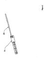
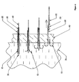
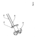
- Figure 1 depicts an installation device for the anchors and other hardware of the present invention, and may be an embodiment of the present invention.
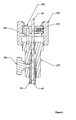
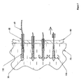
- Figure 2 is a detailed depiction of a portion 2 of Figure 1 :
- This installation device may, for example, be attached to an endoscope or echoendoscope. An example of such an attachment may be found in U.S. Patent No. 6,228,039 .
- the embodiment depicted in Figures 1 and 2 may be assembled as follows.
- the activation cable assembly (including outer sheath 40, pusher 50, tether 60, and suture 20) may be threaded.
- the locknut 330 may be installed prior to threading.
- the locknut 330 may be used to assemble this embodiment together with an endoscope.
- the suture 20 may be pushed through an opening that may be provided in main cylinder 200 and outer sleeve 210.
- outer sleeve 210 may be attached to an endoscope via locknut 330 or via other appropriate attachment device.
- the outer sheath 40 may be attached onto the main cylinder 200 using an appropriate connection, such as a screw (not shown).
- Main cylinder 200 may be fastened to outer sleeve 210 by stop screw 220.
- the stop screw 220 may permit setting the relative position of main cylinder 200 and outer sleeve 210.
- One position that may be useful is one in which outer sheath 40 is consequently adjusted to an appropriate place within a patient.
- Sliding piston 230 may be tensioned and locked using pre-bias latch/release (not shown) as described in U.S. Patent No. 6,228,039 . It may be valuable to identify whether pusher 50 is in correct axial position along outer sheath 40. If not, it may be valuable to adjust the position of pusher 50 accordingly. Stop screw 260 may be used to lock pusher 50 in an appropriate position once adjusted. Calibration cap 250 may be turned on mating threads on main cylinder 200 to adjust the amount of travel upon the release of the compression spring 240.
- End cap 270 may be installed into the end of pusher 50.
- the end cap 270 may be pushed down until the end of its axial travel has been reached.
- the end cap 270 may then be fastened in place with a locking screw 280. This step of installation may be performed without clamp nut 290 or expansion nut 300 in place.
- Clamp nut 290 together with anti-rotation pin 320 and expansion nut 300 may be installed over the tether 60.
- expansion nut 300 may snap over clamp nut 290 to form a subassembly.
- Expansion nut 300 may be screwed down the threads of end cap 270 until the shoulders contact. It may be valuable to confirm that tether 60 is appropriately placed. The locking screw 310 may then be tightened.
- the device as described to this point may be used to deploy the anchor (not shown). After deploying the anchor, the expansion nut 300 may be rotated backwards until the proper expansion of the anchor (not shown) has been obtained. Expansion nut 300 may be connected to tether 60. Tether 60 may be connected to an expander. Turning expansion nut 300 creates relative motion between tether 60 and pusher 50.
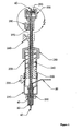
- Figure 3 depicts an embodiment of the present invention in a sectional view.
- This embodiment of the present invention may be inserted into tissue.
- This embodiment includes an expander 30 at a distal end of the apparatus, three anchors 10, a pusher 50, an outer sheath 40, sutures 20, and a tether 60.
- the expander 30, may be forced through a surface in a distal direction.
- the other elements depicted, except for the outer sheath, may also at least partially penetrate the surface.
- one of the anchors 10 may partially penetrate the surface.
- a mechanism (not shown) may be used to retract the expander 30 in a proximal direction.
- the pusher 50 may prevent the anchor 10 from retracting in the proximal direction.
- the expander 30 may force the anchor 10 to expand. This expansion may result in anchor 10 having a greater diameter at its distal end. Thus the anchor 10 may be prevented from moving back through the surface in a proximal direction. However, a tether 60 may provide a tensile force in the proximal direction that may keep the anchor in contact with the penetrated surface. In certain circumstances, it may be advisable to apply an anchor 10 that has a suture 20 attached. Additionally, although this method may use motion of the expander, it may also use motion of the anchor relative to the expander.
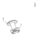
- Figure 4 depicts an embodiment of the present invention that may be an anchor.
- This embodiment includes an expanded-form anchor 10 at a distal end and a suture 20 at a proximal end.
- an anchor 10 may be expanded (shown already expanded), creating a distal region with an effective diameter larger than the hole occupied by the more proximal region.
- a suture 20 may be attached to the expanded anchor 10.
- the suture 20 may, in some embodiments be more easily attached prior to expansion of the anchor 10. In particular, it may be desirable to attach the suture before penetrating a surface with the anchor.
- Figure 5 depicts another embodiment of the present invention that may be an anchor.
- This embodiment includes an anchor 10 at a distal end and a suture 20 at a proximal end.
- the anchor 10 may be in a pre-expansion form. Such a form may be useful, for example, in aiding in the insertion of an anchor through a surface.
- a suture 20 may be attached to the anchor 10 prior to expansion.
- Figure 6 depicts the use of an embodiment of the present invention in four steps.
- the apparatus in the first step (at top), the apparatus as a whole is shown as having been partially inserted through a first layer of tissue 80 (which may, for example be the bowel wall), and into a second layer of tissue 70 (which may, for example, be connective tissue outside the bowel wall).
- the expander 30 may be gradually retracted. This gradual retraction may force anchor 10 in its unexpanded state to partially expand.
- the legs of anchor 10 may be fully expanded.
- the anchor 10 may be retracted until it engages an outer surface of the first layer of tissue 80.
- a suture 20 may remain attached and extend through the first layer of tissue 80.
- the expander 30 and pusher 50 may be eventually completely withdrawn. In this instance the tether 60 may remain attached to the expander 30.
- the anchor 10 may be constructed with legs made from a shape metal alloy, such as a nickel-titanium alloy.
- the legs may be pre-biased to assume an expanded state.
- the legs of the anchors may be maintained in an unexpanded state by means of a restraining sheath. Gradual retraction of the sheath may allow the legs to expand to their pre-biased expanded state. This mechanism may thus make use of the super-elastic properties of the shape-memory alloy.
- a temperature change memory effect of an alloy may also be used, by (for example) training the alloy into an expanded state, bending the legs into an unexpanded state, and then raising the temperature of the alloy above the necessary threshold to return it to the memorized expanded state.
- the temperature change may be accomplished by a variety of means such as the use of a heating element.
- Figure 7 depicts another mean of expanding the anchor, which is not part of the present invention .
- the apparatus in the first step (at top), the apparatus as a whole is shown as having been partially inserted through a first layer of tissue 80 (which may be, for example, the bowel wall), and into a second layer of tissue 70 (which may be, for example, a structure made of muscle tissue such as the diaphragm, and may, as shown here, be adjacent to the first layer of tissue 80).
- the pusher 50 may advance anchor 110 against expander 30. This advancement may force anchor 110 in its unexpanded state to partially expand. Eventually, the anchor 110 may be fully expanded. As shown, the anchor 110 may be left completely within the second layer of tissue 70.
- the tether 60 and the expander 30 may remain partially within the second layer of tissue 70.
- the expander 3 may lie completely with the second layer of tissue 70, and the tether 60 may remain attached and extend from the second layer of tissue 70, through the first layer of tissue 80.
- the pusher 50 may be withdrawn in a proximal direction.
- the expansion may take place by any relative opposing motion of the expander and anchor.
- an anchor may be deployed by prebiasing a leg to an expanded radius, constraining or constricting the leg to a narrower radius, and then removing the restraint.
- Such a technique may include the use of a superelastic leg constrained by a sheath. As the sheath is removed in, for example, a proximal direction, the leg may expand the distal radius of the anchor.
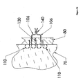
- Figure 8 depicts an embodiment of the present invention including a sensor or treatment delivery device 120.
- the anchor 110 may lie within a second layer of tissue 70.
- a tether 100 may pass through a first layer of tissue 80, and connect the anchor 110 with a sensor or treatment delivery device 120.
- sensors 120 include cameras, electromagnetic sensors, manometry sensors, pH probes, and probes for lumen content sampling.
- Example of treatment delivery devices 120 include pharmaceutical delivery devices; chemotherapy delivery devices; treatment activation devices (e.g,. photodynamic therapy devices); radioisotope containment or delivery devices; thermal or radiofrequency delivery devices; radioisotope containers; thermal, photochemical, and radio frequency delivery devices; and stimulating electrode devices, including pacemakers and nerve stimulators.
- Attachment of the sensor or treatment delivery device 120 to tether 100 may be accomplished by, for example, a nail, screw, bolt, clip, knot, loop, friction mount, or adhesive mechanism.
- a tether may be a suture, but it may also be a more rigid material, and may be an inflexible material.
- Example of materials that may serve as a tether include a wire.
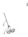
- Figure 9 depicts an embodiment of the present invention including two anchors 110 connected by two tethers 100.
- the anchors and tethers may be inserted as previously described.
- the tethers 100 may further be connected by a lock ring 140. Drawing the tethers together may allow the margins of the first layer of tissue 80 and the second layer of tissue 70 to approximate and close a tear or gap in tissue continuity 130.
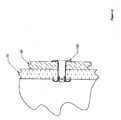
- Figure 10 depicts an anchor 10 with a shoulder 150.
- an anchor 10 shown expanded
- This shoulder 150 may be adapted to prevent over penetration by providing significant resistance to further penetration.
- Figure 11 depicts an anchor 10 with a shoulder 150 passing through a first layer of tissue 80 and a second layer of tissue 70.
- the anchor 10 may be provided with a hollow center.
- the anchor 10 may serve as a stent.
- the stent may, for example, be self expanding or mechanically expandable.
- a balloon may be used to expand the stent, and this may permit the stent to acquire an increased diameter.
- Tabs may be provided directed radially inwardly to convert some of the force of an expander moving in an axial direction into a radially expansive force on the stent.
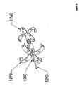
- Figure 12 depicts an anchor 160 with a separate shoulder 170.
- the anchor 160 and the shoulder 170 are in two pieces. These pieces may be adapted to engage one another. This may be accomplished, for example, by providing the pieces with corresponding threadings, by arranging for a light frictional fit, or by tensioning tethers 180 while advancing rod 190.
- One advantage of this design may be the ease of removal.
- the shoulder 170 may be restrained from moving in a proximal direction, and tension may be applied in a proximal direction to the anchor 160. This may force the anchor 160 through the shoulder 170 in a proximal direction, collapsing the anchor 160 in the process.
- Figure 13 depicts an anchor 160 with a separate shoulder 170 as installed. This anchor 160 is otherwise the same as Figure 10 .
- the present invention may be a puncturing or penetrating member that includes or is provided with a tissue anchoring or engaging member.
- the puncturing member may be integral with the tissue anchoring member.
- a barbed needle would integrate both a tissue penetrating and tissue anchoring member.
- the members be separate.
- an anchor may be provided that may be fitted around a tissue penetrating member.
- the tissue penetrating member may also be adapted to be withdrawn in such a manner that it expands the distal radius of the anchor member.
- the anchoring member may involve such devices as crossbars, flanges, hooks, barbs, adhesive, or clips.
- the anchoring member may also be an gas or liquid inflatable element, such as a balloon.
- the puncturing member may be detachable by means of an elongate link such as a thread, wire, strand, or cord.
- such an embodiment of the present invention may include a tissue penetrating device, an outer sleeve 210, and a handle 1410.
- the handle 1410 may include a main cylinder 200 that houses a sliding piston 230, and a compression spring 240.
- the upper (proximal) end of the outer piston may have a shoulder above which the compression spring 240 may be loaded.
- the compression spring 240 when the outer piston is maximally advanced in the main cylinder 200, the compression spring 240 may be relaxed (as opposed to tightly compressed) and handgrip may be in contact with the calibrating sleeve. The outer piston may be retracted by pulling back on the handgrip, thereby loading the compression spring 240 by compressing it.
- the main cylinder may be provided with a trigger that has a spring. Retraction of the outer piston may engage this spring in the groove, thereby locking the outer piston in the locked position. Pressing a button may release this lock, allowing the compression spring to uncoil (relax) and advance the outer piston distally at high velocity.
- the handgrip may be provided with a screw that secures the position of the inner piston 230 that contains the tissue penetrating device.
- the calibrating sleeve may be adjusted proximally to shorten the distance that the outer piston will progress after the spring is released. Thus, the distance of the tissue penetrating device may be precisely calibrated.
- An outer sleeve 210 may be connected and secured to the main cylinder 200 with a screw.
- the outer sleeve 210 may be screwed into the instrumentation channel inlet port of the endoscope or echo-endoscope by screw attachment.
- the outer sheath 40 may screw into the main cylinder. By loosening the screws, the position of the outer sleeve 210 may be adjusted relative to the main cylinder 200. Such an adjustment may adjust the exposed length of the outer sheath 40.
- Figure 15 depicts an embodiment of the invention similar to that shown in Figure 8 .
- the expander has been removed from the anchor 110.
- the suture 105 may be attached to the anchor 110 in a non-coaxial position.
- the suture may have a loop or other member at the proximal end which may be used to attach a sensor or treatment delivery device. It may be advantageous to remove the expander from the anchor 110 because the expander may be used to expand anchors at other locations.
- Attachable devices may include, for example, treatment activation devices (e.g. photodynamic therapy devices), radioisotope containment devices, radioisotope delivery devices, thermal delivery devices, or radio frequency delivery devices.
- the expander may also be used for non-expansion purposes (such as to aid in penetrating tissue) and may (in some instance) not be used for any expansion purpose.
- the deployment mechanism may be the withdrawal or rupture of an encompassing sheath.
- Figure 16 depicts an embodiment of the invention similar to that shown in Figure 9 .
- the expanders have been removed from the anchors 110.
- the suture 106 may be attached to the anchor 110 in a non-coaxial position. It may be advantageous to remove the expander from the anchor 110 because the expander may be used to expand anchors at other locations.
- Sutures 106 may be connected by a lock ring 140.
- FIGS 17A and 17B depict an anchor 1030 with a collapsible shoulder 1040 which is not part of the present invention.
- Anchor assembly 1010 shows the distal legs of an anchor deployed with a collapsible shoulder mechanism at the proximal end of the anchor in its pre-deployed position.
- Shoulder tabs 1040 pivot on the anchor 1030 and may be connected to the anchor 1030 with elastic tension members 1050 such as silicone rubber bands.
- An encompassing sheath may prevent the shoulder tabs 1040 from deploying until it the encompassing sheath 1065 retracted.
- the shoulder tabs 1040 on anchor assembly 1020 may be forced by the elastic tension members 1050 to deploy and form a shoulder that may prevent the distal motion of the anchor 1030.
- the distal legs (if more than one leg is used) may be implemented by a superelastic alloy. In such a configuration, the distal legs may be trained to produce an expanded distal radius, and may be constrained by the encompassing sheath 1065 to a narrower radius. Such an arrangement may require fewer discrete components.
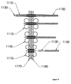
- Figure 18 depicts the use of the collapsible shoulder mechanism in two steps.
- the anchor 1030 is shown penetrating a first layer of tissue 1070 and a second layer of tissue 1080 with its legs already deployed.
- An encompassing sheath 1065 is shown in position restraining the opening of shoulder tabs 1040 against the applied force from the elastic tension member 1050.
- the next step depicts the retraction of the expander 1055 and its associated tether 1060 and the encompassing sheath 1065. These components may be retracted simultaneously or sequentially.
- the encompassing sheath 1065 may be removed first so that the expander 1055 and tether 1060 may stabilize the anchor 1030 prior to deployment of the collapsible shoulder.
- the encompassing sheath 1065 may be removed and the shoulder tabs 1040 may be forced into place against the second layer of tissue 1080 by the force supplied by elastic tension members 1050. As described elsewhere, the encompassing sheath 1065 may also deploy legs by releasing a constraint on the legs. Additionally, the encompassing sheath 1065 may be releasably attached to a distal portion of the legs. The distal portion of the leg may be slightly spooned inward, so that its distal portion extends slightly radially outwardly. As the sheath is retracted, the ends of the legs may be pulled in a proximal direction. This may cause the legs to form an approximately U-shaped configuration which may have the effect of expanding a distal radius of the device. At a suitable time, the encompassing sheath may release the legs after they have formed such a shape. For such a deployment, as with deployment by an expander, it may be advantageous to use a leg formed of a malleable material.
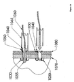
- Figure 19 depicts the use of an expandable stent in combination with an anchor.
- the figure shows a series of four steps of installing an anchor with an expandable stent.
- the combination anchor with expandable stent 1110 may be inserted through two layers of tissue 1170 and 1180.
- An expander 1130 may be located coaxially within the anchor 1110.
- the expander 1130 may be retracted proximally by, for example, a tether (not shown).
- a pusher 1150 may be slipped over the expander 1130 and positioned coaxially with the expander 1130.
- the pusher 1150 may be used to counteract loads applied by the expander 1130 to the anchor 1110.
- the expander 1130 may cause the distal legs of the anchor to deploy.
- the pusher 1150 may cause the proximal legs of the anchor to expand.
- the expander 1130 and pusher 1150 may then make contact with tabs in the anchor. This contact may prevent their further axial motion.
- Application of increased tensile force on the tether (not shown) connected to the expander 1130 and increased compression force on the pusher 1150 may load the anchor 1110 in compression.
- the compression loading of the anchor 1110 may yield the material and cause plastic deformation.
- the anchor body may be formed of an open mesh-like structure that expands in diameter as it yields and is forced into a shorter axial configuration.
- the third step in the figure illustrates an intermediate point of expansion of the diameter.
- the fourth step depicts the anchor fully expanded and the expander 1130 and pusher 1150 retracted from the anchor 1110. It would also be possible to expand the stent portion of the anchor with an inflatable balloon.
- the expandable stent depicted in Figure 19 could be configured with a collapsible shoulder mechanism as illustrated in Figures 17 and 18 if that proved useful.
- Such a stent may be made of a malleable material.
- a stent may be made of a superelastic alloy.
- Such a stent may be constrained to a first diameter by an encompassing sheath (not shown) and may resume a larger diameter after the sheath is removed.
- Figure 20 depicts an anchor 1260 with a separate expandable shoulder 1270.
- the anchor 1260 and the shoulder 1270 are two separate pieces. The pieces may be adapted to engage each other. This may be accomplished as described above for the configuration shown in Figure 12 .
- Tethers 1280 and 1290 may be provided for applying tension to the anchor 1260 and compression to the expandable shoulder 1270.
- the expandable shoulder 1270 may have its legs deployed in the same fashion as described earlier for deploying the legs of an anchor.
- An expander (not shown) may be forced between the legs of the expandable shoulder 1270 in a distal direction, and this forced movement may expand the legs.
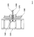
- Figure 21 depicts the embodiment of the invention shown in Figure 20 installed between the stomach 1380 and section of bowel 1370 to create an anastomosis.
- Automatic operation of the penetrating device and pre-biasing the penetrating device may occur via use of, for example, a mechanical spring.
- Other pre-biasing devices may include, for example, compressed air or chemical explosion.
- the penetrating device may thrusts forward into a layer of tissue.
- the penetrating device may experience all (or almost all) of the relative motion and may pass through even hardened tissue.
- the high velocity of the penetrating device may lessen the bending of the penetrating device and may help to overcome the striction effects.
- the penetrating device pre-biased may rush forward after a release (or launch) device provided with the pre-biasing device is operated.
- the use of the penetrating device of the invention may result in avoiding the potentially undesirable (in certain circumstances) repeated reciprocating motion that may be required by conventional techniques and devices.
- the penetrating device that may be located in the passage formed in the endoscope may be surrounded by a protecting sleeve.
- the sleeve may be made of an impenetrable material that may be moved independently of the penetrating device.
- the movable sleeve may protect and may reinforce the penetrating device and may position the penetrating device appropriately, even after the penetrating device has moved out of the passage provided in the endoscope.
- the housing of the pre-biasing device may be set into screw engagement with the opening of the passage provided in the endoscope.
- Adjusting means such as, for example, screws or slides
- the penetrating device may include an operating and pre-biasing device.
- the device may have a main cylinder 200 in which a sliding piston 230 may be provided.
- the sliding piston 230 may have a projection 1420 on its top end.
- a release device 1430 having a spring 1440 may be provided on the main cylinder 200.
- the spring 1440 may be set into a groove 1450 made in the slide piston, when the penetrating device or the slide piston 230 is biased.
- a grip 300 may be provided to move the piston 230, thereby performing automatic penetration.
- a stop pin 280 may be provided, by which the penetrating device may be secured. As long as the spring 240 is released, the grip 300 may remain in contact with a calibration cap 250. The position of the calibration cap 250 may be changed to adjust the end position of the piston 230 and hence the penetration depth of the penetrating device.
- An outer sleeve 210 may be provided on the end of the main cylinder 200, which may be near the penetrating device. This end of the cylinder 200 may hold the pre-biasing and control device in the penetrating device passage provided in the endoscope.
- the main cylinder 200 may be fastened to the outer sleeve 210 by means of a stop pin or screw 220.
- the outer sleeve 210 may be fixed in the open end (inlet port) of the penetrating device passage of the echo-endoscope by means of a screw attachment 1460.
- Standard endoscopes and "interventional" echo-endoscopes can be used.
- the angle of departure of the penetrating device may be adjusted at the echo-endoscope.
- the transducer at the end of the echo-endoscope may be surrounded by a latex balloon.
- the latex balloon can be filled with water during the use of the echo-endoscope.
- the water can serve as a medium between the detection probe and, for example, the intestinal wall.
- the penetrating device may extend through an outer sheath that may be made, for example, of a flexible metal weave or impenetrable plastic.
- the penetrating device may be inserted into the endoscope by the operating- and pre-biasing device until it projects, along with the sleeve, from the lower end of the endoscope.
- a dull stylette may be located in a hollow penetrating device (in some situations in which a hollow penetrating device is desired) and may be flush with or may project by approximately 2 mm from the open end of the penetrating device.
- the proximal end of the penetrating device which may be ready for insertion into the operating and pre-biasing device may be set in screw engagement with the proximal end part of the operating and pre-biasing device.
- the penetrating device can be manually moved back and forth by loosening the stop pin provided on the grip. The position of the penetrating device can therefore be manually adjusted.
- the slide piston 230 may be drawn back greatly. If so, the groove 1450 may move toward the spring 1440, compressing the coil spring 240. When the spring 1440 comes into engagement with the groove 1450, the penetrating device may be pre-biased and can be quickly moved forward by the release device 1430.
- the calibrating sleeve 250 may adjust the depth of penetration of the penetrating device. A coarse adjustment may be possible in accordance with the depth of insertion of the main cylinder 200.
- the main cylinder 200 may be fixed in place by stop pin or screw 220.
- a quick and accurate adjustment of the penetrating device may be performed by manipulation of the outer sleeve 210 provided at the end of the main cylinder 200.
- the stop pin or screw 220 is loosened, while the stop pin 280 at the grip remains tightened, the protective sheath attached to the main cylinder 200 and the penetrating device secured to the slide piston may be inserted together into the outer sleeve 210 until they become visible by the endoscope. Thereafter, the stop pin or screw 220 may be tightened, whereby the calibrating sleeve 250 may adjust the depth of penetration with precision.
- the stylette (if one is used, a stylette is not required for the present invention) may be drawn a little from the hollow penetrating device, releasing the sharp end of the hollow penetrating device.
- the sharp end of the penetrating device first penetrates a first layer of tissue, such as the intestinal wall, and then comes close to a second layer of tissue that is to be punctured.
- the stylette may be removed and may be replaced by any device or substance that may be set into contact with the other end of the hollow penetrating device.
- the stop pin 280 provided on the grip 300 may be loosened to insert the penetrating device into the tissue to be punctured.
- the stop pin 280 may be loosened and the penetrating device may be moved back and forth with respect to the main cylinder 200.
- the release device 1430 may release the elastic spring 240.
- the penetrating device may project forward into the hardened tissue.
- the automation of the installation of anchors one skilled in the art should recognize that it is possible to further automate the installation of anchors. As shown in Figure 3 , for example, it is possible to have multiple anchors staged near the distal end of the apparatus.
- the installation device may, thus, be readily modified to provide a cocking action that compresses the spring, retracts the pusher member through the next anchor and advances a next anchor and pusher member toward the expander.
Landscapes
- Health & Medical Sciences (AREA)
- Life Sciences & Earth Sciences (AREA)
- Surgery (AREA)
- General Health & Medical Sciences (AREA)
- Public Health (AREA)
- Molecular Biology (AREA)
- Animal Behavior & Ethology (AREA)
- Veterinary Medicine (AREA)
- Engineering & Computer Science (AREA)
- Biomedical Technology (AREA)
- Heart & Thoracic Surgery (AREA)
- Medical Informatics (AREA)
- Nuclear Medicine, Radiotherapy & Molecular Imaging (AREA)
- Pathology (AREA)
- Physics & Mathematics (AREA)
- Biophysics (AREA)
- Radiology & Medical Imaging (AREA)
- Optics & Photonics (AREA)
- Rheumatology (AREA)
- Immunology (AREA)
- Vascular Medicine (AREA)
- Surgical Instruments (AREA)
- Prostheses (AREA)
- Materials For Medical Uses (AREA)
Abstract
Description
- The invention relates to a tissue penetrating device for endoscopy or endosonography- guided transluminal interventions using an automated, for example, spring-loaded mechanism with various modifications and uses, including uses in surgical procedures and, in particular, tissue anchoring.
- Endoscopy and endosonography-guided interventions have certain advantages over alternative surgical and percutaneous-guided procedures. Interventions that employ endoscopy or endosonography may avoid some of the harmful effects of alternative procedures.
- One technique that has been explained is a technique for endoscope and endosonography-guided biopsy. Such a technique and associated devices are described, for example, in
U. S. Patent No. 6,228,039 Another technique that exists for deploying a patch over a tissue opening and securing the same with tissue anchors is described in patent applicationWO 01/21247 - A need exists, however, for other diagnostic and therapeutic interventional applications and related devices that may be performed in an endoscopy or endosonography-guided environment.
- In particular, a need exists for such devices and techniques that can traverse a first layer of tissue, such as the wall of the bowel, bladder, or other organ or structure that can be accessed endoscopically, and penetrate into or through another layer of tissue such as the wall of a hollow or solid organ, duct, vessel, or soft tissue structure, such as a muscle or ligament.
- In certain surgical operations, for example, a need exists to be able to connect and create an artificial lumen (anastomosis) between two neighboring luminal structures, such as, for example, two segments of bowel.
- Further, a need exists in certain surgical procedures to attach or affix two neighboring structures, such as the stomach to the diaphragm (gastropexy) or the bladder to the abdom inal wall (cystopexy). Additionally, a need exists to be able to connect a first portion of the stomach with a second portion of the stomach (stomach stapling). A need also exists to be able to affix diagnostic and therapeutic devices to an organ or tissue. For example, a need exists to be able to implant a gastric pacemaker to treat gastroparesis. Furthermore, a need exists to perform the functions described above in a manner that is automated. For example, in circumstances in which it is desired that an operation take place from within a luminal structure, a surgeon may have limited ability to manipulate a needle, anchor, or other penetrating device to perform procedures such as those listed above, and in particular to position tissue or to create an artificial lumen. Thus, a need exists for an appropriate automatic tissue targeting device.
- The present invention may solve the needs in the art stated above and may provide certain advantages over the prior art. The present invention solves the need for the ability to perform additional techniques by providing an apparatus capable of use in such techniques, as defined in the independent claim 1.
- One embodiment of the present invention may be an apparatus including a roughly hollow cylindrical central member having a proximal end and a distal end; a leg member, attached to a distal end of the central member, wherein at least a portion of the leg member is adapted to permit production of an expanded distal radius in the apparatus; a tether attached to a proximal portion of the central member; an expander member, a distal portion of which is aligned co-axially through the central member; and a pusher member aligned co-axially around a proximal portion of the expander member and adapted to prevent the movement in a proximal direction of the central member.
- In an embodiment employing a cylindrical central member, there may be a number of leg members. These leg members may, for example, be segments of the cylinder. In an embodiment shown in
Figure 4 , for example, the leg members are shown curled back, but it may be apparent from that figure that the four legs are each roughly a quarter of the circumference of the cylinder. Of course, there is no requirement that the legs be implemented in such a manner or comprise such a circumference of the cylinder. For example, a cylindrical member may be used. Such a cylindrical member may be adapted to transform from an approximately cylindrical shape to an approximately conical or pyramidal shape. Some examples include a "leg" deployed like the canopy of an umbrella. to . Additionally, a multiplicity of legs, such as 2, 3, 4, or more legs may be used. Such legs may be malleable or elastic. An example material for use as an elastic material is a shape memory alloy such as Nitanol. Other structures that may be used as a leg include, for example, tines, fingers, or hooks. The deployment of legs may be described as an expanding process, or by other terms, such as an unfurling process. - In an embodiment that may be employed in the lumen of a tissue or organ, the distal end may refer to the end most outwardly radial. In general, the distal end refers to the end closest to the first layer of tissue prior to normal use.
- The apparatus described above further includes a pre-biasing device adapted to selectively force at least a portion of the apparatus in a distal direction, and an outer sleeve surrounding the apparatus, wherein the outer sleeve is adapted to be fitted to an endoscope. The outer sleeve may be attached to the described apparatus directly or mediately, or may be slidably positioned relative to the apparatus. The outer sleeve may aid the operator in directing the application of the apparatus to target tissue.
- Another embodiment of the present invention may be the apparatus previously discussed in which the pre-biasing device includes a member such as compressed gas compartment, a coil spring, or a torsion spring. Of course, other pre-biasing devices such as electromagnetic devices (e.g., motors, stepper motors, rail guns, and the like), hydraulic devices, and chemical devices (e.g., a chemical explosive similar to that used in bullet cases or airbags) may be used. Additionally, the pre-biasing device may be located near the proximal or the distal end of the device, and may be activated directly or indirectly by, for example, an electronic switch or relay.
- Methods of use are disclosed, including anchoring a second tissue to a first luminal structure, wherein the second tissue is anchored by use of an expandable anchor that is adapted to perform the steps of penetrating through a first luminal structure, penetrating at least into a second tissue, and holding the second tissue in approximately constant position relative to at least a region of the first luminal structure. The step of holding the second tissue in approximately constant position relative to at least a region of the first luminal structure may be performed by an embodiment of the present invention including an anchor, without regard to the speed or precise manner by which the anchor is inserted.
- In such a method of use, the second tissue may be a luminal structure. Moreover, the first luminal structure may be a hollow organ such as a segment of the bowel (for example, esophagus, stomach, small intestine, and colon), bladder, gallbladder, uterus, or bronchotracheal tree. The first luminal structure may also be a ductal structure such as the bile duct, pancreatic duct, urethra, or ureter. The first luminal structure may also be a vascular structure such as an artery or a vein. The cylindrical central members described above may serve to create a conduit or anastomosis between two luminal structures.
- One embodiment of the present invention may be an apparatus including a substantially hollow central member adapted to permit the passage of a penetrating member adapted to penetrate tissue and a first leg member connected to a distal portion of the central member, wherein the first leg member may be adapted to produce an increase in a distal radius of the apparatus and wherein the increase may be adapted to restrain motion of the apparatus in a proximal direction.
- The first leg member is adapted to expand in radius in response to the proximal motion of the penetrating member.
- An embodiment may, for example, be fashioned with the first leg member including a shape memory alloy. Other parts of the embodiment may also include shape memory alloy, such as, for example, the hollow central member.
- In a particular embodiment, the first leg member may include a first end connected to a distal portion, and a second end that extends approximately proximally prior to increasing the radius of the apparatus. The first leg member may, for example, include a first end connected to a distal portion, and may also include a second end that extends approximately distally prior to increasing the radius of the apparatus.
- In a further embodiment of the present invention, the apparatus may also include a second leg member connected to a proximal portion of the central member, wherein the second leg member is adapted to produce an increase in the proximal radius of the apparatus and wherein the increase is adapted to restrain motion of the apparatus in a distal direction.
- In a particular embodiment, the central member may be adapted to be a stent.
- Furthermore, the central member may be adapted to be expandable. Additionally, the central member may include a shape memory alloy mesh. Such a mesh may be an expandable mesh that is trained to an expanded diameter but restrained to a narrower diameter by a removable encompassing sheath.
- A further embodiment of the present invention may also include a tab connected to the central member and directed radially inward. The tab may be adapted to translate force in an axial proximal direction into force in a radially outward direction.
- The accompanying drawings illustrating an embodiment of the invention and together with the description serve to explain the principles of the invention.
-
-
Figure 1 is a drawing of an installation device for the anchors and other hardware of the present invention. -
Figure 2 is a detail drawing of a relevant portion ofFigure 1 . -
Figure 3 is a sectional view of an embodiment of the present invention. -
Figure 4 is a perspective view drawing of an embodiment of the present invention that may be an anchor and may be, as shown, in an expanded state with leg members deployed. -
Figure 5 is another perspective view drawing of an embodiment of the present invention that may be an anchor and may be, as shown, in an unexpanded state. -
Figure 6 is a four step side view partial cutaway drawing of an embodiment of the present invention in use. -
Figure 7 is another four step side view partial cutaway drawing of an example of expanding the anchor. -
Figure 8 is a drawing of an embodiment of the present invention including an anchor with an expander and a sensor or treatment delivery device attached to a tether. -
Figure 9 is a drawing of an embodiment of the present invention including two anchors (with expanders) connected by two tethers. -
Figure 10 is a drawing of an anchor with a shoulder. -
Figure 11 is a cross-section drawing of an anchor with a shoulder that may serve as a stent. -
Figure 12 is a drawing of an anchor with a separate shoulder. -
Figure 13 is a drawing of an anchor with a separate shoulder installed on the anchor. -
Figure 14 is a drawing of an alternative embodiment of the present invention including a release device. -
Figure 15 is a drawing of an embodiment of the present invention including an anchor without an expander and further including a suture with a loop at the proximal end, with the loop optionally attached to a sensor or treatment delivery device. -
Figure 16 is a drawing of an embodiment of the present invention including two anchors (without expanders) connected by two sutures. - Figures 17A and 17B is a drawing of an anchor with a collapsible shoulder, which is not part of the present invention.
-
Figure 18 is a two-step sectional view drawing of the collapsible shoulder anchor in use, not part of the present invention. -
Figure 19 is a four-step sectional view of an embodiment of the invention with an anchor that may serve as an expandable stent. -
Figure 20 is a perspective view drawing of an embodiment of the present invention with an anchor with a separate expandable shoulder. -
Figure 21 is a sectional view drawing of an anchor (with an expandable shoulder) situated in a portion of bowel and securing another luminal tissue structure to the bowel. - It is to be understood that the present invention is not limited to the particular methodology, compounds, materials, manufacturing techniques, uses, and applications, described herein, as these may vary. It is also to be understood that the terminology used herein is used for the purpose of describing particular embodiments only, and is not intended to limit the scope of the present invention. It must be noted that as used herein and in the appended claims, the singular forms "a, " "an, "and "the" include the plural reference unless the context clearly dictates otherwise. Thus, for example, a reference to "a suture" is a reference to one or more sutures and includes equivalents thereof known to those skilled in the art. The materials that may be used in conjunction with the present invention may include conventional materials such as stainless steel, other surgical alloys of steel, various biocompatible plastics and elastomers, and other conventional materials. In general it may be valuable to avoid using materials that are likely to cause allergic reactions or inflammation, unless such a result is desired.
- Reference herein to the term "endoscope" refers not only to conventional endoscopes, but also to any rigid, semi-rigid, or flexible optical instrument for use in visual examinations of the interior of the human body. Such examinations may include, for example, examinations of bodily canals or hollow organs such as stomachs, intestines, colons, or bladders. The term "endoscope" also includes echo-endoscopes, which may include an ultrasound transducer at, for example, the tip of the device.
- The present invention is an embodiment that permits the automation of a tissue penetrating device by means of a pre-biasing device, which includes a member such as compressed gas compartment, a coil spring, or a torsion spring. In a specific embodiment, an integrated spring coil component, such as a compression spring component, may be used. Although a compression spring coil may be one component that may be used to forward-bias a portion of the device, other components may be used as well. For example, other types of elastically deformed mechanical spring elements, compressed air, chemical combustion, or magnetic repulsion (or attraction) may also be used a pre-biasing device.
- The compression spring, or other pre-biasing device, may be loaded. On release of the component, a tissue-penetrating component may shoot forward at high velocity. The velocity that may be desirable may depend on the tissue whose penetration is desired. A high velocity operation avoids striction effect and hence is more repeatable and accurate. Thus, the device may be able to penetrate in a more predictable and precisely calculable fashion. Further, the device may penetrate more than one tissue in a single forward movement or in more than one forward movement.
- Thus, the device may be used to penetrate through the wall of a luminal structure into and through a wall of an adjacent luminal structure. Thereafter, the adjacent tissue may be engaged by an anchoring or connecting member. Thus, the device may be able to create an anastomotic connection between two lumens.
- In certain embodiments, a device according to the present invention may be a tissue penetrating device that is inserted though the instrumentation channel of an endoscope, echo-endoscope, or the like. The handle of the device may be attached to the inlet port of the endoscope or echo-endoscope. Examples of such endoscopes are found, for example, in
U.S. Pat. Nos. 6,638,213 ;6,614,595 ; and6,520,908 . The tissue penetrating device may be manually advanced or retracted. Additionally, the forward-biasing device (for example, a compression spring) may be loaded and released. This may enable the tissue penetrating device to shoot forward with high velocity on the release of the device, which may occur via the release (or depression) of a trigger. - The tissue penetrating device may, for example, take the form of a barbed needle. The needle may be housed in a protective outer sheath. The outer sheath may serve to protect the instrumentation channel in the endoscope from the needle, as well as to protect the needle. The outer sheath may be adapted to be separate from the tissue penetrating device. Thus, the outer sheath may be moved independently of the tissue penetrating device. The outer sheath may further serve as a guide for the tissue penetrating device. Finally, the outer sheath may also serve to dilate or enlarge a tissue penetration tract.
- The handle of the device may be screwed and thereby securely anchored into the inlet port of the instrumentation channel of the endoscope using a Luer lock mechanism. This may be useful to prevent the handle from back-firing after the forward-biasing device is activated.
- In the example of a spring-loaded embodiment, the distance of forward (or as it will be referred to herein, distal) movement of the tissue penetrating device may be controlled at the handle. For example, in one embodiment, the degree to which the spring is compressed or the degree to which the spring is permitted to travel may precisely control the distal movement of the tissue penetrating device. In an embodiment in which an anchor is to be inserted, the method of insertion is not essential to the operation of the anchor, although controlled, rapid insertion may accrue the benefits described.
-
Figure 1 depicts an installation device for the anchors and other hardware of the present invention, and may be an embodiment of the present invention.Figure 2 is a detailed depiction of a portion 2 ofFigure 1 : This installation device may, for example, be attached to an endoscope or echoendoscope. An example of such an attachment may be found inU.S. Patent No. 6,228,039 . - The embodiment depicted in
Figures 1 and2 may be assembled as follows. The activation cable assembly (includingouter sheath 40,pusher 50,tether 60, and suture 20) may be threaded. Thelocknut 330 may be installed prior to threading. Thelocknut 330 may be used to assemble this embodiment together with an endoscope. - Next the
suture 20 may be pushed through an opening that may be provided inmain cylinder 200 andouter sleeve 210. Next,outer sleeve 210 may be attached to an endoscope vialocknut 330 or via other appropriate attachment device. Theouter sheath 40 may be attached onto themain cylinder 200 using an appropriate connection, such as a screw (not shown).Main cylinder 200 may be fastened toouter sleeve 210 bystop screw 220. Thestop screw 220 may permit setting the relative position ofmain cylinder 200 andouter sleeve 210. One position that may be useful is one in whichouter sheath 40 is consequently adjusted to an appropriate place within a patient. - Sliding
piston 230 may be tensioned and locked using pre-bias latch/release (not shown) as described inU.S. Patent No. 6,228,039 . It may be valuable to identify whetherpusher 50 is in correct axial position alongouter sheath 40. If not, it may be valuable to adjust the position ofpusher 50 accordingly. Stopscrew 260 may be used to lockpusher 50 in an appropriate position once adjusted.Calibration cap 250 may be turned on mating threads onmain cylinder 200 to adjust the amount of travel upon the release of thecompression spring 240. -
End cap 270 may be installed into the end ofpusher 50. Theend cap 270 may be pushed down until the end of its axial travel has been reached. Theend cap 270 may then be fastened in place with a lockingscrew 280. This step of installation may be performed withoutclamp nut 290 orexpansion nut 300 in place. -
Clamp nut 290 together withanti-rotation pin 320 andexpansion nut 300 may be installed over thetether 60. In this embodiment,expansion nut 300 may snap overclamp nut 290 to form a subassembly. -
Expansion nut 300 may be screwed down the threads ofend cap 270 until the shoulders contact. It may be valuable to confirm thattether 60 is appropriately placed. The lockingscrew 310 may then be tightened. - The device as described to this point may be used to deploy the anchor (not shown). After deploying the anchor, the
expansion nut 300 may be rotated backwards until the proper expansion of the anchor (not shown) has been obtained.Expansion nut 300 may be connected to tether 60.Tether 60 may be connected to an expander. Turningexpansion nut 300 creates relative motion betweentether 60 andpusher 50. -
Figure 3 depicts an embodiment of the present invention in a sectional view. This embodiment of the present invention may be inserted into tissue. This embodiment includes anexpander 30 at a distal end of the apparatus, threeanchors 10, apusher 50, anouter sheath 40, sutures 20, and atether 60. In this example, theexpander 30, may be forced through a surface in a distal direction. The other elements depicted, except for the outer sheath, may also at least partially penetrate the surface. Thus, for example, one of theanchors 10 may partially penetrate the surface. A mechanism (not shown) may be used to retract theexpander 30 in a proximal direction. Thepusher 50 may prevent theanchor 10 from retracting in the proximal direction. As theexpander 30 retracts, it may force theanchor 10 to expand. This expansion may result inanchor 10 having a greater diameter at its distal end. Thus theanchor 10 may be prevented from moving back through the surface in a proximal direction. However, atether 60 may provide a tensile force in the proximal direction that may keep the anchor in contact with the penetrated surface. In certain circumstances, it may be advisable to apply ananchor 10 that has asuture 20 attached. Additionally, although this method may use motion of the expander, it may also use motion of the anchor relative to the expander. -
Figure 4 depicts an embodiment of the present invention that may be an anchor. This embodiment includes an expanded-form anchor 10 at a distal end and asuture 20 at a proximal end. As shown here, ananchor 10 may be expanded (shown already expanded), creating a distal region with an effective diameter larger than the hole occupied by the more proximal region. Asuture 20 may be attached to the expandedanchor 10. Thesuture 20 may, in some embodiments be more easily attached prior to expansion of theanchor 10. In particular, it may be desirable to attach the suture before penetrating a surface with the anchor. -
Figure 5 depicts another embodiment of the present invention that may be an anchor. This embodiment includes ananchor 10 at a distal end and asuture 20 at a proximal end. As shown, theanchor 10 may be in a pre-expansion form. Such a form may be useful, for example, in aiding in the insertion of an anchor through a surface. As shown here, asuture 20 may be attached to theanchor 10 prior to expansion. -
Figure 6 depicts the use of an embodiment of the present invention in four steps. In the first step (at top), the apparatus as a whole is shown as having been partially inserted through a first layer of tissue 80 (which may, for example be the bowel wall), and into a second layer of tissue 70 (which may, for example, be connective tissue outside the bowel wall). In the next three steps (proceeding downward), theexpander 30 may be gradually retracted. This gradual retraction may forceanchor 10 in its unexpanded state to partially expand. Eventually, the legs ofanchor 10 may be fully expanded. In this instance, theanchor 10 may be retracted until it engages an outer surface of the first layer oftissue 80. Asuture 20 may remain attached and extend through the first layer oftissue 80. Theexpander 30 andpusher 50 may be eventually completely withdrawn. In this instance thetether 60 may remain attached to theexpander 30. - An alternative means of expanding the
anchor 10 which is not part of the present invention, may be accomplished as follows. Theanchor 10 may be constructed with legs made from a shape metal alloy, such as a nickel-titanium alloy. The legs may be pre-biased to assume an expanded state. However, the legs of the anchors may be maintained in an unexpanded state by means of a restraining sheath. Gradual retraction of the sheath may allow the legs to expand to their pre-biased expanded state. This mechanism may thus make use of the super-elastic properties of the shape-memory alloy. Alternatively, a temperature change memory effect of an alloy may also be used, by (for example) training the alloy into an expanded state, bending the legs into an unexpanded state, and then raising the temperature of the alloy above the necessary threshold to return it to the memorized expanded state. The temperature change may be accomplished by a variety of means such as the use of a heating element. -
Figure 7 depicts another mean of expanding the anchor, which is not part of the present invention . In the first step (at top), the apparatus as a whole is shown as having been partially inserted through a first layer of tissue 80 (which may be, for example, the bowel wall), and into a second layer of tissue 70 (which may be, for example, a structure made of muscle tissue such as the diaphragm, and may, as shown here, be adjacent to the first layer of tissue 80). In the next three steps (proceeding downward), thepusher 50 may advanceanchor 110 againstexpander 30. This advancement may forceanchor 110 in its unexpanded state to partially expand. Eventually, theanchor 110 may be fully expanded. As shown, theanchor 110 may be left completely within the second layer oftissue 70. In this embodiment, thetether 60 and theexpander 30 may remain partially within the second layer oftissue 70. For example, the expander 3 may lie completely with the second layer oftissue 70, and thetether 60 may remain attached and extend from the second layer oftissue 70, through the first layer oftissue 80. Thepusher 50 may be withdrawn in a proximal direction. As previously discussed, the expansion may take place by any relative opposing motion of the expander and anchor. Additionally, an anchor may be deployed by prebiasing a leg to an expanded radius, constraining or constricting the leg to a narrower radius, and then removing the restraint. Such a technique may include the use of a superelastic leg constrained by a sheath. As the sheath is removed in, for example, a proximal direction, the leg may expand the distal radius of the anchor. -
Figure 8 depicts an embodiment of the present invention including a sensor ortreatment delivery device 120. In this embodiment, theanchor 110 may lie within a second layer oftissue 70. Atether 100, may pass through a first layer oftissue 80, and connect theanchor 110 with a sensor ortreatment delivery device 120. Example ofsensors 120 include cameras, electromagnetic sensors, manometry sensors, pH probes, and probes for lumen content sampling. Example oftreatment delivery devices 120 include pharmaceutical delivery devices; chemotherapy delivery devices; treatment activation devices (e.g,. photodynamic therapy devices); radioisotope containment or delivery devices; thermal or radiofrequency delivery devices; radioisotope containers; thermal, photochemical, and radio frequency delivery devices; and stimulating electrode devices, including pacemakers and nerve stimulators. Attachment of the sensor ortreatment delivery device 120 to tether 100 may be accomplished by, for example, a nail, screw, bolt, clip, knot, loop, friction mount, or adhesive mechanism. A tether may be a suture, but it may also be a more rigid material, and may be an inflexible material. Example of materials that may serve as a tether include a wire. -
Figure 9 depicts an embodiment of the present invention including twoanchors 110 connected by twotethers 100. In this example, the anchors and tethers may be inserted as previously described. However, thetethers 100 may further be connected by alock ring 140. Drawing the tethers together may allow the margins of the first layer oftissue 80 and the second layer oftissue 70 to approximate and close a tear or gap intissue continuity 130. -
Figure 10 depicts ananchor 10 with ashoulder 150. In this embodiment of the present invention, an anchor 10 (shown expanded) may be provided with ashoulder 150. Thisshoulder 150 may be adapted to prevent over penetration by providing significant resistance to further penetration. -
Figure 11 depicts ananchor 10 with ashoulder 150 passing through a first layer oftissue 80 and a second layer oftissue 70. In this example, theanchor 10 may be provided with a hollow center. Thus, when in place, as shown, theanchor 10 may serve as a stent. The stent may, for example, be self expanding or mechanically expandable. A balloon may be used to expand the stent, and this may permit the stent to acquire an increased diameter. Tabs may be provided directed radially inwardly to convert some of the force of an expander moving in an axial direction into a radially expansive force on the stent. -
Figure 12 depicts ananchor 160 with aseparate shoulder 170. In this embodiment, theanchor 160 and theshoulder 170 are in two pieces. These pieces may be adapted to engage one another. This may be accomplished, for example, by providing the pieces with corresponding threadings, by arranging for a light frictional fit, or by tensioningtethers 180 while advancingrod 190. One advantage of this design may be the ease of removal. In particular, theshoulder 170, may be restrained from moving in a proximal direction, and tension may be applied in a proximal direction to theanchor 160. This may force theanchor 160 through theshoulder 170 in a proximal direction, collapsing theanchor 160 in the process. -
Figure 13 depicts ananchor 160 with aseparate shoulder 170 as installed. Thisanchor 160 is otherwise the same asFigure 10 . - It is an object of the invention to provide a device that efficiently and effectively penetrates tissue in a precisely targeted manner for a diagnostic or therapeutic endoscopy or endonography-guided transluminal procedures.
- The present invention may be a puncturing or penetrating member that includes or is provided with a tissue anchoring or engaging member. The puncturing member may be integral with the tissue anchoring member. For example, a barbed needle would integrate both a tissue penetrating and tissue anchoring member. In another embodiment the members be separate. For example, an anchor may be provided that may be fitted around a tissue penetrating member. The tissue penetrating member may also be adapted to be withdrawn in such a manner that it expands the distal radius of the anchor member. The anchoring member may involve such devices as crossbars, flanges, hooks, barbs, adhesive, or clips. The anchoring member may also be an gas or liquid inflatable element, such as a balloon. The puncturing member may be detachable by means of an elongate link such as a thread, wire, strand, or cord.
- Referring to
Figure 14 , such an embodiment of the present invention may include a tissue penetrating device, anouter sleeve 210, and ahandle 1410. Thehandle 1410 may include amain cylinder 200 that houses a slidingpiston 230, and acompression spring 240. The upper (proximal) end of the outer piston may have a shoulder above which thecompression spring 240 may be loaded. - In a particular embodiment, when the outer piston is maximally advanced in the
main cylinder 200, thecompression spring 240 may be relaxed (as opposed to tightly compressed) and handgrip may be in contact with the calibrating sleeve. The outer piston may be retracted by pulling back on the handgrip, thereby loading thecompression spring 240 by compressing it. - The main cylinder may be provided with a trigger that has a spring. Retraction of the outer piston may engage this spring in the groove, thereby locking the outer piston in the locked position. Pressing a button may release this lock, allowing the compression spring to uncoil (relax) and advance the outer piston distally at high velocity.
- The handgrip may be provided with a screw that secures the position of the
inner piston 230 that contains the tissue penetrating device. The calibrating sleeve may be adjusted proximally to shorten the distance that the outer piston will progress after the spring is released. Thus, the distance of the tissue penetrating device may be precisely calibrated. - An
outer sleeve 210 may be connected and secured to themain cylinder 200 with a screw. Theouter sleeve 210 may be screwed into the instrumentation channel inlet port of the endoscope or echo-endoscope by screw attachment. Theouter sheath 40 may screw into the main cylinder. By loosening the screws, the position of theouter sleeve 210 may be adjusted relative to themain cylinder 200. Such an adjustment may adjust the exposed length of theouter sheath 40. -
Figure 15 depicts an embodiment of the invention similar to that shown inFigure 8 . In this embodiment, the expander has been removed from theanchor 110. Thesuture 105 may be attached to theanchor 110 in a non-coaxial position. The suture may have a loop or other member at the proximal end which may be used to attach a sensor or treatment delivery device. It may be advantageous to remove the expander from theanchor 110 because the expander may be used to expand anchors at other locations. Attachable devices may include, for example, treatment activation devices (e.g. photodynamic therapy devices), radioisotope containment devices, radioisotope delivery devices, thermal delivery devices, or radio frequency delivery devices. Although the invention is described in terms of an expander, the expander may also be used for non-expansion purposes (such as to aid in penetrating tissue) and may (in some instance) not be used for any expansion purpose. For example, if a leg (or a plurality of legs) of shape memory alloy is used, the deployment mechanism may be the withdrawal or rupture of an encompassing sheath. -
Figure 16 depicts an embodiment of the invention similar to that shown inFigure 9 . In this embodiment, the expanders have been removed from theanchors 110. Thesuture 106 may be attached to theanchor 110 in a non-coaxial position. It may be advantageous to remove the expander from theanchor 110 because the expander may be used to expand anchors at other locations.Sutures 106 may be connected by alock ring 140. - Figures 17A and 17B depict an
anchor 1030 with acollapsible shoulder 1040 which is not part of the present invention.Anchor assembly 1010 shows the distal legs of an anchor deployed with a collapsible shoulder mechanism at the proximal end of the anchor in its pre-deployed position.Shoulder tabs 1040 pivot on theanchor 1030 and may be connected to theanchor 1030 withelastic tension members 1050 such as silicone rubber bands. An encompassing sheath (not shown) may prevent theshoulder tabs 1040 from deploying until it the encompassingsheath 1065 retracted. Once thesheath 1065 is retracted, theshoulder tabs 1040 onanchor assembly 1020 may be forced by theelastic tension members 1050 to deploy and form a shoulder that may prevent the distal motion of theanchor 1030. The distal legs (if more than one leg is used) may be implemented by a superelastic alloy. In such a configuration, the distal legs may be trained to produce an expanded distal radius, and may be constrained by the encompassingsheath 1065 to a narrower radius. Such an arrangement may require fewer discrete components. -
Figure 18 depicts the use of the collapsible shoulder mechanism in two steps. In the first step (at top), theanchor 1030 is shown penetrating a first layer oftissue 1070 and a second layer oftissue 1080 with its legs already deployed. An encompassingsheath 1065 is shown in position restraining the opening ofshoulder tabs 1040 against the applied force from theelastic tension member 1050. The next step depicts the retraction of theexpander 1055 and its associatedtether 1060 and the encompassingsheath 1065. These components may be retracted simultaneously or sequentially. The encompassingsheath 1065 may be removed first so that theexpander 1055 andtether 1060 may stabilize theanchor 1030 prior to deployment of the collapsible shoulder. The encompassingsheath 1065 may be removed and theshoulder tabs 1040 may be forced into place against the second layer oftissue 1080 by the force supplied byelastic tension members 1050. As described elsewhere, the encompassingsheath 1065 may also deploy legs by releasing a constraint on the legs. Additionally, the encompassingsheath 1065 may be releasably attached to a distal portion of the legs. The distal portion of the leg may be slightly spooned inward, so that its distal portion extends slightly radially outwardly. As the sheath is retracted, the ends of the legs may be pulled in a proximal direction. This may cause the legs to form an approximately U-shaped configuration which may have the effect of expanding a distal radius of the device. At a suitable time, the encompassing sheath may release the legs after they have formed such a shape. For such a deployment, as with deployment by an expander, it may be advantageous to use a leg formed of a malleable material. -
Figure 19 depicts the use of an expandable stent in combination with an anchor. The figure shows a series of four steps of installing an anchor with an expandable stent. In the first step (at top), the combination anchor withexpandable stent 1110 may be inserted through two layers oftissue expander 1130 may be located coaxially within theanchor 1110. Theexpander 1130 may be retracted proximally by, for example, a tether (not shown). Apusher 1150 may be slipped over theexpander 1130 and positioned coaxially with theexpander 1130. Thepusher 1150 may be used to counteract loads applied by theexpander 1130 to theanchor 1110. In the second step, theexpander 1130 may cause the distal legs of the anchor to deploy. Simultaneously, thepusher 1150 may cause the proximal legs of the anchor to expand. Theexpander 1130 andpusher 1150 may then make contact with tabs in the anchor. This contact may prevent their further axial motion. Application of increased tensile force on the tether (not shown) connected to theexpander 1130 and increased compression force on thepusher 1150 may load theanchor 1110 in compression. - The compression loading of the
anchor 1110 may yield the material and cause plastic deformation. The anchor body may be formed of an open mesh-like structure that expands in diameter as it yields and is forced into a shorter axial configuration. The third step in the figure illustrates an intermediate point of expansion of the diameter. Finally, the fourth step depicts the anchor fully expanded and theexpander 1130 andpusher 1150 retracted from theanchor 1110. It would also be possible to expand the stent portion of the anchor with an inflatable balloon. The expandable stent depicted inFigure 19 could be configured with a collapsible shoulder mechanism as illustrated inFigures 17 and18 if that proved useful. - Such a stent may be made of a malleable material. Similarly, a stent may be made of a superelastic alloy. Such a stent may be constrained to a first diameter by an encompassing sheath (not shown) and may resume a larger diameter after the sheath is removed.
-
Figure 20 depicts ananchor 1260 with a separateexpandable shoulder 1270. In this embodiment, theanchor 1260 and theshoulder 1270 are two separate pieces. The pieces may be adapted to engage each other. This may be accomplished as described above for the configuration shown inFigure 12 .Tethers anchor 1260 and compression to theexpandable shoulder 1270. Theexpandable shoulder 1270 may have its legs deployed in the same fashion as described earlier for deploying the legs of an anchor. An expander (not shown) may be forced between the legs of theexpandable shoulder 1270 in a distal direction, and this forced movement may expand the legs.Figure 21 depicts the embodiment of the invention shown inFigure 20 installed between thestomach 1380 and section ofbowel 1370 to create an anastomosis. - Automatic operation of the penetrating device and pre-biasing the penetrating device may occur via use of, for example, a mechanical spring. Other pre-biasing devices may include, for example, compressed air or chemical explosion. In the example of a spring biasing device, as soon as the spring is released, the penetrating device may thrusts forward into a layer of tissue. By virtue of the greater inertia of the mass of the endoscope (if one is used in conjunction with the present invention), the penetrating device may experience all (or almost all) of the relative motion and may pass through even hardened tissue. The high velocity of the penetrating device may lessen the bending of the penetrating device and may help to overcome the striction effects.
- More specifically, according to the device of the present invention, the penetrating device pre-biased may rush forward after a release (or launch) device provided with the pre-biasing device is operated.
- Further, the use of the penetrating device of the invention may result in avoiding the potentially undesirable (in certain circumstances) repeated reciprocating motion that may be required by conventional techniques and devices.
- In this case, the penetrating device that may be located in the passage formed in the endoscope may be surrounded by a protecting sleeve. The sleeve may be made of an impenetrable material that may be moved independently of the penetrating device. The movable sleeve may protect and may reinforce the penetrating device and may position the penetrating device appropriately, even after the penetrating device has moved out of the passage provided in the endoscope.
- In order to reliably move the penetrating device forward and to prevent the pre-biasing device from projecting, the housing of the pre-biasing device may be set into screw engagement with the opening of the passage provided in the endoscope. Adjusting means (such as, for example, screws or slides) may precisely adjust the position of the penetrating device and the forward movement of the pre-biasing device.
- Referring to
Figure 14 , the penetrating device may include an operating and pre-biasing device. The device may have amain cylinder 200 in which a slidingpiston 230 may be provided. The slidingpiston 230 may have aprojection 1420 on its top end. To theprojection 1420 there may be attached aspring 240 for pre-biasing the penetrating device. Arelease device 1430 having aspring 1440 may be provided on themain cylinder 200. Thespring 1440 may be set into agroove 1450 made in the slide piston, when the penetrating device or theslide piston 230 is biased. At the end of theslide piston 230, which may be distant from the penetrating device, agrip 300 may be provided to move thepiston 230, thereby performing automatic penetration. On the grip 300 astop pin 280 may be provided, by which the penetrating device may be secured. As long as thespring 240 is released, thegrip 300 may remain in contact with acalibration cap 250. The position of thecalibration cap 250 may be changed to adjust the end position of thepiston 230 and hence the penetration depth of the penetrating device. - An
outer sleeve 210 may be provided on the end of themain cylinder 200, which may be near the penetrating device. This end of thecylinder 200 may hold the pre-biasing and control device in the penetrating device passage provided in the endoscope. Themain cylinder 200 may be fastened to theouter sleeve 210 by means of a stop pin orscrew 220. Theouter sleeve 210 may be fixed in the open end (inlet port) of the penetrating device passage of the echo-endoscope by means of ascrew attachment 1460. - Standard endoscopes and "interventional" echo-endoscopes can be used. Using an interventional echo-endoscope, the angle of departure of the penetrating device may be adjusted at the echo-endoscope. The transducer at the end of the echo-endoscope may be surrounded by a latex balloon. The latex balloon can be filled with water during the use of the echo-endoscope. The water can serve as a medium between the detection probe and, for example, the intestinal wall.
- The penetrating device may extend through an outer sheath that may be made, for example, of a flexible metal weave or impenetrable plastic. The penetrating device may be inserted into the endoscope by the operating- and pre-biasing device until it projects, along with the sleeve, from the lower end of the endoscope. In certain cases, it may be desired that the penetrating device tip be beveled and that the distal end of the penetrating device be sandblasted, pitted, or otherwise altered to improve the resolution of ultrasonic imaging.
- A dull stylette may be located in a hollow penetrating device (in some situations in which a hollow penetrating device is desired) and may be flush with or may project by approximately 2 mm from the open end of the penetrating device. The proximal end of the penetrating device, which may be ready for insertion into the operating and pre-biasing device may be set in screw engagement with the proximal end part of the operating and pre-biasing device.
- In the device according to the invention, the penetrating device can be manually moved back and forth by loosening the stop pin provided on the grip. The position of the penetrating device can therefore be manually adjusted.
- Referring to
Figure 14 , theslide piston 230 may be drawn back greatly. If so, thegroove 1450 may move toward thespring 1440, compressing thecoil spring 240. When thespring 1440 comes into engagement with thegroove 1450, the penetrating device may be pre-biased and can be quickly moved forward by therelease device 1430. The calibratingsleeve 250 may adjust the depth of penetration of the penetrating device. A coarse adjustment may be possible in accordance with the depth of insertion of themain cylinder 200. At this stage in the use of the device, themain cylinder 200 may be fixed in place by stop pin orscrew 220. - A quick and accurate adjustment of the penetrating device may be performed by manipulation of the
outer sleeve 210 provided at the end of themain cylinder 200. Once the stop pin or screw 220 is loosened, while thestop pin 280 at the grip remains tightened, the protective sheath attached to themain cylinder 200 and the penetrating device secured to the slide piston may be inserted together into theouter sleeve 210 until they become visible by the endoscope. Thereafter, the stop pin or screw 220 may be tightened, whereby the calibratingsleeve 250 may adjust the depth of penetration with precision. The stylette (if one is used, a stylette is not required for the present invention) may be drawn a little from the hollow penetrating device, releasing the sharp end of the hollow penetrating device. The sharp end of the penetrating device first penetrates a first layer of tissue, such as the intestinal wall, and then comes close to a second layer of tissue that is to be punctured. - As soon as the penetrating device reaches the tissue to be punctured, the stylette may be removed and may be replaced by any device or substance that may be set into contact with the other end of the hollow penetrating device.
- The
stop pin 280 provided on thegrip 300 may be loosened to insert the penetrating device into the tissue to be punctured. To accomplish manual puncture, thestop pin 280 may be loosened and the penetrating device may be moved back and forth with respect to themain cylinder 200. When the manual puncture is difficult to achieve or when the tissue is hard to penetrate, therelease device 1430 may release theelastic spring 240. Thus, the penetrating device may project forward into the hardened tissue. - Regarding one goal of this invention, the automation of the installation of anchors, one skilled in the art should recognize that it is possible to further automate the installation of anchors. As shown in
Figure 3 , for example, it is possible to have multiple anchors staged near the distal end of the apparatus. The installation device may, thus, be readily modified to provide a cocking action that compresses the spring, retracts the pusher member through the next anchor and advances a next anchor and pusher member toward the expander. - Other embodiments of the invention will be apparent to those skilled in the art from consideration of the specification and the practice of the invention disclosed herein.
Claims (3)
- An apparatus comprising:a tissue anchor (10) including a substantially hollow cylindrical central member having a proximal end and a distal end, and a leg member, attached to the distal end of said central member;a suture (20) attached to a proximal portion of said central member;an expander member (30) having a proximal portion and a distal portion, said proximal portion connected to a tether (60), and said distal portion is aligned co-axially through said central member;a pusher member (50) aligned co-axially around a proximal portion of said expander member and positioned to prevent the movement in a proximal direction of said central member when the expander member is moved in a proximal direction ; anda pre-biasing device for selectively forcing at least a portion of said apparatus in a distal direction;characterised in that the distal portion of the expander member extends distally from the leg member such that proximal movement of the expander member causes expansion of at least a portion of said leg member.
- The apparatus of claim 1,
wherein said apparatus has an outer sleeve surrounding said apparatus, wherein said outer sleeve is adapted to be fitted to an endoscope. - The apparatus of claim 1, wherein said pre-biasing device includes a member selected from the group consisting of a compressed gas compartment, a coil spring, a torsion spring, an electromagnetic device, a hydraulic device and a chemical device.
Priority Applications (1)
| Application Number | Priority Date | Filing Date | Title |
|---|---|---|---|
| EP10003201A EP2389877A3 (en) | 2004-04-12 | 2005-04-08 | Automated transluminal tissue targeting and anchoring devices |
Applications Claiming Priority (2)
| Application Number | Priority Date | Filing Date | Title |
|---|---|---|---|
| US10/822,138 US20050228413A1 (en) | 2004-04-12 | 2004-04-12 | Automated transluminal tissue targeting and anchoring devices and methods |
| PCT/US2005/011921 WO2005099591A2 (en) | 2004-04-12 | 2005-04-08 | Automated transluminal tissue targeting and anchoring devices and methods |
Related Child Applications (1)
| Application Number | Title | Priority Date | Filing Date |
|---|---|---|---|
| EP10003201.0 Division-Into | 2010-03-25 |
Publications (3)
| Publication Number | Publication Date |
|---|---|
| EP1755462A2 EP1755462A2 (en) | 2007-02-28 |
| EP1755462A4 EP1755462A4 (en) | 2009-07-01 |
| EP1755462B1 true EP1755462B1 (en) | 2011-03-16 |
Family
ID=35061568
Family Applications (2)
| Application Number | Title | Priority Date | Filing Date |
|---|---|---|---|
| EP05732207A Not-in-force EP1755462B1 (en) | 2004-04-12 | 2005-04-08 | Automated transluminal tissue targeting and anchoring devices and methods |
| EP10003201A Withdrawn EP2389877A3 (en) | 2004-04-12 | 2005-04-08 | Automated transluminal tissue targeting and anchoring devices |
Family Applications After (1)
| Application Number | Title | Priority Date | Filing Date |
|---|---|---|---|
| EP10003201A Withdrawn EP2389877A3 (en) | 2004-04-12 | 2005-04-08 | Automated transluminal tissue targeting and anchoring devices |
Country Status (6)
| Country | Link |
|---|---|
| US (1) | US20050228413A1 (en) |
| EP (2) | EP1755462B1 (en) |
| JP (2) | JP2007532200A (en) |
| AT (1) | ATE501675T1 (en) |
| DE (1) | DE602005026934D1 (en) |
| WO (1) | WO2005099591A2 (en) |
Cited By (2)
| Publication number | Priority date | Publication date | Assignee | Title |
|---|---|---|---|---|
| US10888444B2 (en) | 2017-11-01 | 2021-01-12 | Boston Scientific Scimed, Inc. | Esophageal stent including a valve member |
| US11304795B2 (en) | 2017-10-25 | 2022-04-19 | Boston Scientific Scimed, Inc. | Stent with atraumatic spacer |
Families Citing this family (96)
| Publication number | Priority date | Publication date | Assignee | Title |
|---|---|---|---|---|
| US9173658B2 (en) * | 2000-03-06 | 2015-11-03 | Covidien Lp | Apparatus and method for performing a bypass procedure in a digestive system |
| US9060844B2 (en) | 2002-11-01 | 2015-06-23 | Valentx, Inc. | Apparatus and methods for treatment of morbid obesity |
| US7837669B2 (en) | 2002-11-01 | 2010-11-23 | Valentx, Inc. | Devices and methods for endolumenal gastrointestinal bypass |
| US7632287B2 (en) | 2004-02-20 | 2009-12-15 | Endogastric Solutions, Inc. | Tissue fixation devices and assemblies for deploying the same |
| US20050187565A1 (en) | 2004-02-20 | 2005-08-25 | Baker Steve G. | Tissue fixation devices and a transoral endoscopic gastroesophageal flap valve restoration device and assembly using same |
| US8425539B2 (en) | 2004-04-12 | 2013-04-23 | Xlumena, Inc. | Luminal structure anchoring devices and methods |
| EP1750595A4 (en) | 2004-05-07 | 2008-10-22 | Valentx Inc | Devices and methods for attaching an endolumenal gastrointestinal implant |
| US8257394B2 (en) | 2004-05-07 | 2012-09-04 | Usgi Medical, Inc. | Apparatus and methods for positioning and securing anchors |
| DE102004022590A1 (en) * | 2004-05-07 | 2005-12-01 | Feussner, Hubertus, Prof.Dr.med. | Blind rivet for adaptation of biological tissue and device for setting the same, in particular through the instrument channel of an endoscope |
| US20050251167A1 (en) * | 2004-05-07 | 2005-11-10 | Ethicon Endo-Surgery, Inc. | Instrument for effecting anastomosis of respective tissues defining two body lumens |
| US9463012B2 (en) * | 2004-10-26 | 2016-10-11 | P Tech, Llc | Apparatus for guiding and positioning an implant |
| US20060116697A1 (en) | 2004-11-30 | 2006-06-01 | Esophyx, Inc. | Flexible transoral endoscopic gastroesophageal flap valve restoration device and method |
| EP1858396B1 (en) | 2004-12-08 | 2019-02-06 | Boston Scientific Scimed, Inc. | Apparatus for performing needle guided interventions |
| US20060167481A1 (en) | 2005-01-25 | 2006-07-27 | Esophyx, Inc. | Slitted tissue fixation devices and assemblies for deploying the same |
| DE602006013946D1 (en) | 2005-02-08 | 2010-06-10 | Koninkl Philips Electronics Nv | SYSTEM FOR PERCUTANEOUS GLOSSOPLASTICS |
| US7789890B2 (en) * | 2005-03-30 | 2010-09-07 | Ethicon Endo-Surgery, Inc. | Harness and balloon catheter assembly and method for use in anastomosis procedures |
| US8777967B2 (en) | 2005-06-09 | 2014-07-15 | Xlumena, Inc. | Methods and devices for anchoring to tissue |
| US8784437B2 (en) | 2005-06-09 | 2014-07-22 | Xlumena, Inc. | Methods and devices for endosonography-guided fundoplexy |
| US20070005082A1 (en) | 2005-06-29 | 2007-01-04 | Esophyx, Inc. | Apparatus and method for manipulating stomach tissue and treating gastroesophageal reflux disease |
| US20070038232A1 (en) | 2005-08-12 | 2007-02-15 | Kraemer Stefan J M | Apparatus and method for securing the stomach to the diaphragm for use, for example, in treating hiatal hernias and gastroesophageal reflux disease |
| US20070088373A1 (en) | 2005-10-18 | 2007-04-19 | Endogastric Solutions, Inc. | Invaginator for gastroesophageal flap valve restoration device |
| WO2007059199A2 (en) | 2005-11-14 | 2007-05-24 | C.R. Bard, Inc. | Sling anchor system |
| US7850712B2 (en) | 2005-11-15 | 2010-12-14 | Ethicon Endo-Surgery, Inc. | Self-shielding suture anchor |
| US9161754B2 (en) | 2012-12-14 | 2015-10-20 | Endogastric Solutions, Inc. | Apparatus and method for concurrently forming a gastroesophageal valve and tightening the lower esophageal sphincter |
| EP1959830A4 (en) * | 2005-12-02 | 2010-01-06 | Given Imaging Ltd | System and device for in vivo procedures |
| US7881797B2 (en) | 2006-04-25 | 2011-02-01 | Valentx, Inc. | Methods and devices for gastrointestinal stimulation |
| US8870916B2 (en) | 2006-07-07 | 2014-10-28 | USGI Medical, Inc | Low profile tissue anchors, tissue anchor systems, and methods for their delivery and use |
| US8403196B2 (en) | 2006-09-08 | 2013-03-26 | Covidien Lp | Dissection tip and introducer for surgical instrument |
| US8136711B2 (en) | 2006-09-08 | 2012-03-20 | Tyco Healthcare Group Lp | Dissection tip and introducer for surgical instrument |
| WO2008033950A2 (en) | 2006-09-13 | 2008-03-20 | C. R. Bard, Inc. | Urethral support system |
| EP2104458A4 (en) | 2007-01-08 | 2014-12-31 | Endogastric Solutions | Connected fasteners, delivery device and method |
| US20080228202A1 (en) * | 2007-03-16 | 2008-09-18 | Ethicon Endo-Surgery, Inc. | Endoscopic tissue approximation system |
| US20080228199A1 (en) * | 2007-03-16 | 2008-09-18 | Ethicon Endo-Surgery, Inc. | Endoscopic tissue approximation method |
| EP2164558A4 (en) | 2007-06-08 | 2010-08-04 | Valentx Inc | Methods and devices for intragastric support of functional or prosthetic gastrointestinal devices |
| MX2009013568A (en) * | 2007-06-11 | 2010-04-21 | Valentx Inc | Endoscopic delivery devices and methods. |
| AU2008276122A1 (en) * | 2007-07-17 | 2009-01-22 | Cook Medical Technologies Llc | Rivet introduction system |
| US9597080B2 (en) * | 2007-09-24 | 2017-03-21 | Covidien Lp | Insertion shroud for surgical instrument |
| US8206280B2 (en) | 2007-11-13 | 2012-06-26 | C. R. Bard, Inc. | Adjustable tissue support member |
| US20090143760A1 (en) * | 2007-11-30 | 2009-06-04 | Jacques Van Dam | Methods, Devices, Kits and Systems for Defunctionalizing the Gallbladder |
| US8795343B2 (en) * | 2008-02-07 | 2014-08-05 | DePuy Synthes Products, LLC | Pelvic Cable Solution |
| US8454632B2 (en) | 2008-05-12 | 2013-06-04 | Xlumena, Inc. | Tissue anchor for securing tissue layers |
| US20090281379A1 (en) | 2008-05-12 | 2009-11-12 | Xlumena, Inc. | System and method for transluminal access |
| EP2345373B1 (en) * | 2008-07-30 | 2020-04-29 | Neotract, Inc. | Anchor delivery system with replaceable cartridge |
| US9186128B2 (en) | 2008-10-01 | 2015-11-17 | Covidien Lp | Needle biopsy device |
| US9782565B2 (en) | 2008-10-01 | 2017-10-10 | Covidien Lp | Endoscopic ultrasound-guided biliary access system |
| US8968210B2 (en) | 2008-10-01 | 2015-03-03 | Covidien LLP | Device for needle biopsy with integrated needle protection |
| US9332973B2 (en) | 2008-10-01 | 2016-05-10 | Covidien Lp | Needle biopsy device with exchangeable needle and integrated needle protection |
| US11298113B2 (en) | 2008-10-01 | 2022-04-12 | Covidien Lp | Device for needle biopsy with integrated needle protection |
| US20190167302A9 (en) * | 2008-10-10 | 2019-06-06 | Surgiquest, Inc. | Low-profile surgical access devices with anchoring |
| US8388349B2 (en) * | 2009-01-14 | 2013-03-05 | Ams Research Corporation | Anastomosis deployment force training tool |
| US8906037B2 (en) | 2009-03-18 | 2014-12-09 | Endogastric Solutions, Inc. | Methods and devices for forming a tissue fold |
| JP2012522595A (en) | 2009-04-03 | 2012-09-27 | メタモディクス インコーポレイテッド | Modular gastrointestinal prosthesis |
| US9173760B2 (en) | 2009-04-03 | 2015-11-03 | Metamodix, Inc. | Delivery devices and methods for gastrointestinal implants |
| US8702641B2 (en) | 2009-04-03 | 2014-04-22 | Metamodix, Inc. | Gastrointestinal prostheses having partial bypass configurations |
| US9278019B2 (en) | 2009-04-03 | 2016-03-08 | Metamodix, Inc | Anchors and methods for intestinal bypass sleeves |
| US9364259B2 (en) | 2009-04-21 | 2016-06-14 | Xlumena, Inc. | System and method for delivering expanding trocar through a sheath |
| US9901347B2 (en) | 2009-05-29 | 2018-02-27 | Terus Medical, Inc. | Biliary shunts, delivery systems, and methods of using the same |
| JP5535313B2 (en) | 2009-05-29 | 2014-07-02 | エックスルミナ, インコーポレイテッド | Device and method for deploying a stent across adjacent tissue layers |
| IN2012DN00316A (en) | 2009-07-10 | 2015-05-08 | Metamodix Inc | |
| US8613756B2 (en) | 2009-10-30 | 2013-12-24 | Depuy Mitek, Llc | Knotless suture anchor |
| US10959840B2 (en) | 2010-01-20 | 2021-03-30 | Micro Interventional Devices, Inc. | Systems and methods for affixing a prosthesis to tissue |
| US10058314B2 (en) | 2010-01-20 | 2018-08-28 | Micro Interventional Devices, Inc. | Tissue closure device and method |
| US10743854B2 (en) | 2010-01-20 | 2020-08-18 | Micro Interventional Devices, Inc. | Tissue closure device and method |
| WO2011091185A1 (en) | 2010-01-20 | 2011-07-28 | New Hope Ventures, Lp | Tissue closure device and method |
| US9980708B2 (en) * | 2010-01-20 | 2018-05-29 | Micro Interventional Devices, Inc. | Tissue closure device and method |
| CN103501735B (en) | 2011-03-08 | 2016-04-06 | W.L.戈尔及同仁股份有限公司 | For ostomy medical treatment device |
| US20130066338A1 (en) | 2011-09-09 | 2013-03-14 | Richard Romley | Methods and devices for manipulating and fastening tissue |
| US9955957B2 (en) | 2011-09-09 | 2018-05-01 | Endogastric Solutions, Inc. | Methods and devices for manipulating and fastening tissue |
| US9572571B2 (en) | 2011-09-09 | 2017-02-21 | Endogastric Solutions, Inc. | Methods and devices for manipulating and fastening tissue |
| US9010608B2 (en) | 2011-12-14 | 2015-04-21 | Covidien Lp | Releasable buttress retention on a surgical stapler |
| US9113868B2 (en) | 2011-12-15 | 2015-08-25 | Ethicon Endo-Surgery, Inc. | Devices and methods for endoluminal plication |
| US9173657B2 (en) | 2011-12-15 | 2015-11-03 | Ethicon Endo-Surgery, Inc. | Devices and methods for endoluminal plication |
| US8992547B2 (en) | 2012-03-21 | 2015-03-31 | Ethicon Endo-Surgery, Inc. | Methods and devices for creating tissue plications |
| EP2854654B1 (en) | 2012-05-17 | 2019-11-06 | Boston Scientific Scimed, Inc. | Devices for access across adjacent tissue layers |
| US9681975B2 (en) | 2012-05-31 | 2017-06-20 | Valentx, Inc. | Devices and methods for gastrointestinal bypass |
| US20130324906A1 (en) | 2012-05-31 | 2013-12-05 | Valen Tx, Inc. | Devices and methods for gastrointestinal bypass |
| US9050168B2 (en) | 2012-05-31 | 2015-06-09 | Valentx, Inc. | Devices and methods for gastrointestinal bypass |
| US20140046347A1 (en) * | 2012-08-10 | 2014-02-13 | W. L. Gore & Associates, Inc. | Devices, systems and methods for engaging tissue |
| EP2945566A4 (en) | 2013-01-15 | 2016-10-26 | Metamodix Inc | System and method for affecting intestinal microbial flora |
| AU2014218701A1 (en) | 2013-02-21 | 2015-09-10 | Xlumena, Inc. | Devices and methods for forming an anastomosis |
| US9936951B2 (en) | 2013-03-12 | 2018-04-10 | Covidien Lp | Interchangeable tip reload |
| US9757264B2 (en) | 2013-03-13 | 2017-09-12 | Valentx, Inc. | Devices and methods for gastrointestinal bypass |
| JP2016524946A (en) * | 2013-06-20 | 2016-08-22 | クラシール インコーポレイティド | Intestinal open acupuncture treatment device |
| US9700312B2 (en) | 2014-01-28 | 2017-07-11 | Covidien Lp | Surgical apparatus |
| US11712230B2 (en) | 2014-05-02 | 2023-08-01 | W. L. Gore & Associates, Inc. | Occluder and anastomosis devices |
| US11439396B2 (en) | 2014-05-02 | 2022-09-13 | W. L. Gore & Associates, Inc. | Occluder and anastomosis devices |
| US10004509B2 (en) | 2014-05-02 | 2018-06-26 | W. L. Gore & Associates, Inc. | Anastomosis devices |
| JP6596071B2 (en) * | 2014-08-21 | 2019-10-23 | コーニンクレッカ フィリップス エヌ ヴェ | Tongue advancer implant or removal tool for tongue manipulation system |
| GB2530487B (en) * | 2014-09-17 | 2016-12-28 | Cardiomech As | Device for heart repair |
| US9622897B1 (en) | 2016-03-03 | 2017-04-18 | Metamodix, Inc. | Pyloric anchors and methods for intestinal bypass sleeves |
| JP7044374B2 (en) | 2016-05-19 | 2022-03-30 | メタモディクス インコーポレイテッド | Extraction device |
| US10966754B2 (en) | 2017-01-17 | 2021-04-06 | Avation Medical, Inc. | Devices, systems, and methods for delivery of electrical microstimulators |
| US10220214B2 (en) * | 2017-01-17 | 2019-03-05 | Veressa Medical, Inc. | Devices, systems, and methods for improving pelvic floor dysfunction |
| US11724075B2 (en) | 2017-04-18 | 2023-08-15 | W. L. Gore & Associates, Inc. | Deployment constraining sheath that enables staged deployment by device section |
| AU2019251188B2 (en) * | 2018-04-11 | 2021-06-03 | Boston Scientific Scimed, Inc. | Devices with an adjustable effective working shaft length |
| AU2020219093A1 (en) | 2019-02-07 | 2021-08-26 | Nxt Biomedical, Llc | Rivet shunt and method of deployment |
Family Cites Families (109)
| Publication number | Priority date | Publication date | Assignee | Title |
|---|---|---|---|---|
| US2127903A (en) * | 1936-05-05 | 1938-08-23 | Davis & Geck Inc | Tube for surgical purposes and method of preparing and using the same |
| US3039468A (en) * | 1959-01-07 | 1962-06-19 | Joseph L Price | Trocar and method of treating bloat |
| US3717151A (en) * | 1971-03-11 | 1973-02-20 | R Collett | Flesh penetrating apparatus |
| US3874388A (en) * | 1973-02-12 | 1975-04-01 | Ochsner Med Found Alton | Shunt defect closure system |
| US3970090A (en) * | 1975-02-03 | 1976-07-20 | Physio Medics, Inc. | Catheter |
| US4990139A (en) * | 1986-09-10 | 1991-02-05 | Jang G David | Tandem independently inflatable/deflatable multiple diameter balloon angioplasty catheter systems |
| JPH0755222B2 (en) * | 1986-12-12 | 1995-06-14 | オリンパス光学工業株式会社 | Treatment tool |
| DE69020075T2 (en) * | 1989-08-09 | 1995-11-16 | Bard Inc C R | Catheter guide and guidewire for rapid catheter replacement. |
| US5211651A (en) * | 1989-08-18 | 1993-05-18 | Evi Corporation | Catheter atherotome |
| US5024655A (en) * | 1989-09-05 | 1991-06-18 | Freeman Andrew B | Epidural catheter apparatus and associated method |
| US5330497A (en) * | 1989-11-22 | 1994-07-19 | Dexide, Inc. | Locking trocar sleeve |
| US4950285A (en) * | 1989-11-27 | 1990-08-21 | Wilk Peter J | Suture device |
| US5207229A (en) * | 1989-12-21 | 1993-05-04 | Advanced Biomedical Devices, Inc. | Flexibility steerable guidewire with inflatable balloon |
| US5197971A (en) * | 1990-03-02 | 1993-03-30 | Bonutti Peter M | Arthroscopic retractor and method of using the same |
| US5345927A (en) * | 1990-03-02 | 1994-09-13 | Bonutti Peter M | Arthroscopic retractors |
| US5234447A (en) * | 1990-08-28 | 1993-08-10 | Robert L. Kaster | Side-to-end vascular anastomotic staple apparatus |
| CA2052310A1 (en) * | 1990-10-09 | 1992-04-10 | Thomas L. Foster | Surgical access sheath |
| WO1992008513A1 (en) * | 1990-11-20 | 1992-05-29 | Interventional Thermodynamics, Inc. | Tension guide and dilator |
| US5275610A (en) * | 1991-05-13 | 1994-01-04 | Cook Incorporated | Surgical retractors and method of use |
| US5183464A (en) * | 1991-05-17 | 1993-02-02 | Interventional Thermodynamics, Inc. | Radially expandable dilator |
| US5713870A (en) * | 1991-11-27 | 1998-02-03 | Yoon; Inbae | Retractable safety penetrating instrument with laterally extendable spring strip |
| US5395349A (en) * | 1991-12-13 | 1995-03-07 | Endovascular Technologies, Inc. | Dual valve reinforced sheath and method |
| US5224945A (en) * | 1992-01-13 | 1993-07-06 | Interventional Technologies, Inc. | Compressible/expandable atherectomy cutter |
| US5209727A (en) * | 1992-01-29 | 1993-05-11 | Interventional Technologies, Inc. | Guide wire with integral angioplasty balloon |
| US5707362A (en) * | 1992-04-15 | 1998-01-13 | Yoon; Inbae | Penetrating instrument having an expandable anchoring portion for triggering protrusion of a safety member and/or retraction of a penetrating member |
| US5536248A (en) * | 1992-05-11 | 1996-07-16 | Arrow Precision Products, Inc. | Method and apparatus for electrosurgically obtaining access to the biliary tree and placing a stent therein |
| US5443484A (en) * | 1992-06-16 | 1995-08-22 | Loma Linda University Medical Center | Trocar and method for endoscopic surgery |
| EP0596162B1 (en) * | 1992-11-06 | 2002-08-21 | Texas Instruments Incorporated | hypodermic needle with a protrusion |
| US5304198A (en) * | 1992-11-13 | 1994-04-19 | Target Therapeutics | Single-lumen balloon catheter having a directional valve |
| US5972000A (en) * | 1992-11-13 | 1999-10-26 | Influence Medical Technologies, Ltd. | Non-linear anchor inserter device and bone anchors |
| US5431676A (en) * | 1993-03-05 | 1995-07-11 | Innerdyne Medical, Inc. | Trocar system having expandable port |
| US5462561A (en) * | 1993-08-05 | 1995-10-31 | Voda; Jan K. | Suture device |
| US5449355A (en) * | 1993-11-24 | 1995-09-12 | Valleylab Inc. | Retrograde tissue splitter and method |
| US5415664A (en) * | 1994-03-30 | 1995-05-16 | Corvita Corporation | Method and apparatus for introducing a stent or a stent-graft |
| US5843127A (en) * | 1994-08-22 | 1998-12-01 | Le Medical Technologies, Inc. | Fixation device and method for installing same |
| US5620457A (en) * | 1994-11-23 | 1997-04-15 | Medinol Ltd. | Catheter balloon |
| US5904697A (en) * | 1995-02-24 | 1999-05-18 | Heartport, Inc. | Devices and methods for performing a vascular anastomosis |
| US5495851A (en) * | 1995-03-23 | 1996-03-05 | Roanoke Gastroenterology, P.C. | Use of endoscopic ultrasound and stimulated bilary drainage in the diagnosis of cholecystitis and microlithiasis |
| US6575967B1 (en) * | 1995-03-24 | 2003-06-10 | The Board Of Regents Of The University Of Nebraska | Method and systems for volumetric tissue ablation |
| US5868740A (en) * | 1995-03-24 | 1999-02-09 | Board Of Regents-Univ Of Nebraska | Method for volumetric tissue ablation |
| US5857999A (en) * | 1995-05-05 | 1999-01-12 | Imagyn Medical Technologies, Inc. | Small diameter introducer for laparoscopic instruments |
| CA2234389A1 (en) * | 1995-10-13 | 1997-04-17 | Transvascular, Inc. | A device, system and method for interstitial transvascular intervention |
| US6190353B1 (en) * | 1995-10-13 | 2001-02-20 | Transvascular, Inc. | Methods and apparatus for bypassing arterial obstructions and/or performing other transvascular procedures |
| US5709671A (en) * | 1995-10-16 | 1998-01-20 | Ethicon Endo-Surgery, Inc. | Trocar having an improved tip configuration |
| US5620456A (en) * | 1995-10-20 | 1997-04-15 | Lasersurge, Inc. | Trocar assembly |
| WO1997016119A1 (en) * | 1995-10-30 | 1997-05-09 | Children's Medical Center Corporation | Self-centering umbrella-type septal closure device |
| EP0932426A4 (en) * | 1996-02-02 | 2003-07-30 | Transvascular Inc | Methods and apparatus for connecting openings formed in adjacent blood vessels or other anatomical structures |
| US5951588A (en) * | 1996-02-29 | 1999-09-14 | Moenning; Stephen P. | Apparatus and method for protecting a port site opening in the wall of a body cavity |
| US5893856A (en) * | 1996-06-12 | 1999-04-13 | Mitek Surgical Products, Inc. | Apparatus and method for binding a first layer of material to a second layer of material |
| US6358264B2 (en) * | 1996-07-24 | 2002-03-19 | Surgical Design Corporation | Surgical instruments with movable member |
| US5935107A (en) * | 1996-10-07 | 1999-08-10 | Applied Medical Resources Corporation | Apparatus and method for surgically accessing a body cavity |
| US6682536B2 (en) * | 2000-03-22 | 2004-01-27 | Advanced Stent Technologies, Inc. | Guidewire introducer sheath |
| AU721415B2 (en) * | 1996-11-08 | 2000-07-06 | Converge Medical, Inc. | Percutaneous bypass graft and securing system |
| DE29708149U1 (en) * | 1997-05-07 | 1997-09-25 | Binmöller, Kenneth F., Dr., 20251 Hamburg | Biopsy device |
| US6074416A (en) * | 1997-10-09 | 2000-06-13 | St. Jude Medical Cardiovascular Group, Inc. | Wire connector structures for tubular grafts |
| AU1923999A (en) * | 1998-01-30 | 1999-08-16 | Vascular Science Inc. | Medical graft connector or plug structures, and methods of making and installingsame |
| US5944738A (en) * | 1998-02-06 | 1999-08-31 | Aga Medical Corporation | Percutaneous catheter directed constricting occlusion device |
| US7027398B2 (en) * | 2001-04-12 | 2006-04-11 | General Instrument Corporation | Method and apparatus for monitoring voice conversations from customer premises equipment |
| EP1079740B1 (en) * | 1998-05-21 | 2007-08-29 | Christopher J. Walshe | A tissue anchor system |
| US6402770B1 (en) * | 1998-06-01 | 2002-06-11 | Avatar Design & Development, Inc. | Method and apparatus for placing and maintaining a percutaneous tube into a body cavity |
| US6746489B2 (en) * | 1998-08-31 | 2004-06-08 | Wilson-Cook Medical Incorporated | Prosthesis having a sleeve valve |
| US20030032975A1 (en) * | 1999-01-06 | 2003-02-13 | Bonutti Peter M. | Arthroscopic retractors |
| US6022359A (en) * | 1999-01-13 | 2000-02-08 | Frantzen; John J. | Stent delivery system featuring a flexible balloon |
| US6428550B1 (en) * | 1999-05-18 | 2002-08-06 | Cardica, Inc. | Sutureless closure and deployment system for connecting blood vessels |
| US6241758B1 (en) * | 1999-05-28 | 2001-06-05 | Advanced Cardiovascular Systems, Inc. | Self-expanding stent delivery system and method of use |
| EP1210014A1 (en) * | 1999-09-07 | 2002-06-05 | Microvena Corporation | Retrievable septal defect closure device |
| WO2001021247A1 (en) | 1999-09-20 | 2001-03-29 | Appriva Medical, Inc. | Method and apparatus for closing a body lumen |
| US6231561B1 (en) * | 1999-09-20 | 2001-05-15 | Appriva Medical, Inc. | Method and apparatus for closing a body lumen |
| US6964674B1 (en) * | 1999-09-20 | 2005-11-15 | Nuvasive, Inc. | Annulotomy closure device |
| US6436119B1 (en) * | 1999-09-30 | 2002-08-20 | Raymedica, Inc. | Adjustable surgical dilator |
| JP2001095747A (en) * | 1999-09-30 | 2001-04-10 | Olympus Optical Co Ltd | Electronic endoscope |
| US6592596B1 (en) * | 2000-05-10 | 2003-07-15 | Scimed Life Systems, Inc. | Devices and related methods for securing a tissue fold |
| US8105351B2 (en) * | 2001-05-18 | 2012-01-31 | C.R. Bard, Inc. | Method of promoting tissue adhesion |
| US6921361B2 (en) * | 2000-07-24 | 2005-07-26 | Olympus Corporation | Endoscopic instrument for forming an artificial valve |
| US6322580B1 (en) * | 2000-09-01 | 2001-11-27 | Angiolink Corporation | Wound site management and wound closure device |
| US7037324B2 (en) * | 2000-09-15 | 2006-05-02 | United States Surgical Corporation | Knotless tissue anchor |
| US6736828B1 (en) * | 2000-09-29 | 2004-05-18 | Scimed Life Systems, Inc. | Method for performing endoluminal fundoplication and apparatus for use in the method |
| JP2002177201A (en) | 2000-10-02 | 2002-06-25 | Olympus Optical Co Ltd | Endoscope |
| US6695867B2 (en) * | 2002-02-21 | 2004-02-24 | Integrated Vascular Systems, Inc. | Plunger apparatus and methods for delivering a closure device |
| US6614595B2 (en) | 2001-02-16 | 2003-09-02 | Olympus Optical Co., Ltd. | Stereo endoscope |
| US6535764B2 (en) * | 2001-05-01 | 2003-03-18 | Intrapace, Inc. | Gastric treatment and diagnosis device and method |
| US6916332B2 (en) * | 2001-05-23 | 2005-07-12 | Scimed Life Systems, Inc. | Endoluminal fundoplication device and related method for installing tissue fastener |
| US20020188301A1 (en) * | 2001-06-11 | 2002-12-12 | Dallara Mark Douglas | Tissue anchor insertion system |
| US7115136B2 (en) * | 2001-06-20 | 2006-10-03 | Park Medical Llc | Anastomotic device |
| US6629988B2 (en) * | 2001-08-28 | 2003-10-07 | Ethicon, Inc. | Composite staple for completing an anastomosis |
| US6702835B2 (en) * | 2001-09-07 | 2004-03-09 | Core Medical, Inc. | Needle apparatus for closing septal defects and methods for using such apparatus |
| US6776784B2 (en) * | 2001-09-06 | 2004-08-17 | Core Medical, Inc. | Clip apparatus for closing septal defects and methods of use |
| US7736336B2 (en) * | 2001-09-13 | 2010-06-15 | Allegiance Corporation | Paracentesis device having multiple detachable components |
| US7892247B2 (en) * | 2001-10-03 | 2011-02-22 | Bioconnect Systems, Inc. | Devices and methods for interconnecting vessels |
| JP2003116982A (en) * | 2001-10-10 | 2003-04-22 | Medicos Hirata:Kk | System for drainage of gallbladder through duodenum under endoscope |
| US6893431B2 (en) * | 2001-10-15 | 2005-05-17 | Scimed Life Systems, Inc. | Medical device for delivering patches |
| US7169161B2 (en) * | 2001-11-06 | 2007-01-30 | Possis Medical, Inc. | Guidewire having occlusive device and repeatably crimpable proximal end |
| US7182771B1 (en) * | 2001-12-20 | 2007-02-27 | Russell A. Houser | Vascular couplers, techniques, methods, and accessories |
| WO2003071962A2 (en) * | 2002-02-25 | 2003-09-04 | Yeung Jeffrey E | Expandable fastener with compressive grips |
| US7077850B2 (en) * | 2002-05-01 | 2006-07-18 | Scimed Life Systems, Inc. | Tissue fastening devices and related insertion tools and methods |
| US7377897B1 (en) * | 2002-05-02 | 2008-05-27 | Kunkel Sanford S | Portal device |
| AU2003245344A1 (en) * | 2002-05-28 | 2003-12-12 | Endobionics, Inc. | Methods and apparatus for aspiration and priming of inflatable structures in catheters |
| US7309334B2 (en) * | 2002-07-23 | 2007-12-18 | Von Hoffmann Gerard | Intracranial aspiration catheter |
| US6902535B2 (en) * | 2002-08-26 | 2005-06-07 | Kansey Nash Corporation | Guide-wire mounted balloon modulation device and methods of use |
| JP2004113398A (en) * | 2002-09-25 | 2004-04-15 | Osamu Sasagawa | Articulator, method for fabricating denture and method for adjusting occlusal vertical dimension in fabrication of denture |
| GB0307826D0 (en) * | 2003-04-04 | 2003-05-07 | Univ London | A device for transfixing and joining tissue |
| US20050075654A1 (en) * | 2003-10-06 | 2005-04-07 | Brian Kelleher | Methods and devices for soft tissue securement |
| WO2005055834A1 (en) * | 2003-11-20 | 2005-06-23 | Nmt Medical, Inc. | Device, with electrospun fabric, for a percutaneous transluminal procedure, and methods thereof |
| US20060142790A1 (en) * | 2004-03-23 | 2006-06-29 | Michael Gertner | Methods and devices to facilitate connections between body lumens |
| EP1858396B1 (en) * | 2004-12-08 | 2019-02-06 | Boston Scientific Scimed, Inc. | Apparatus for performing needle guided interventions |
| US8777967B2 (en) * | 2005-06-09 | 2014-07-15 | Xlumena, Inc. | Methods and devices for anchoring to tissue |
| US20090143760A1 (en) * | 2007-11-30 | 2009-06-04 | Jacques Van Dam | Methods, Devices, Kits and Systems for Defunctionalizing the Gallbladder |
| US20110137394A1 (en) * | 2009-05-29 | 2011-06-09 | Xlumena, Inc. | Methods and systems for penetrating adjacent tissue layers |
| JP5535313B2 (en) * | 2009-05-29 | 2014-07-02 | エックスルミナ, インコーポレイテッド | Device and method for deploying a stent across adjacent tissue layers |
-
2004
- 2004-04-12 US US10/822,138 patent/US20050228413A1/en not_active Abandoned
-
2005
- 2005-04-08 EP EP05732207A patent/EP1755462B1/en not_active Not-in-force
- 2005-04-08 DE DE602005026934T patent/DE602005026934D1/en active Active
- 2005-04-08 JP JP2007507526A patent/JP2007532200A/en active Pending
- 2005-04-08 AT AT05732207T patent/ATE501675T1/en not_active IP Right Cessation
- 2005-04-08 WO PCT/US2005/011921 patent/WO2005099591A2/en active Application Filing
- 2005-04-08 EP EP10003201A patent/EP2389877A3/en not_active Withdrawn
-
2010
- 2010-12-06 JP JP2010272069A patent/JP2012000443A/en active Pending
Cited By (3)
| Publication number | Priority date | Publication date | Assignee | Title |
|---|---|---|---|---|
| US11304795B2 (en) | 2017-10-25 | 2022-04-19 | Boston Scientific Scimed, Inc. | Stent with atraumatic spacer |
| US12064333B2 (en) | 2017-10-25 | 2024-08-20 | Boston Scientific Scimed, Inc. | Stent with atraumatic spacer |
| US10888444B2 (en) | 2017-11-01 | 2021-01-12 | Boston Scientific Scimed, Inc. | Esophageal stent including a valve member |
Also Published As
| Publication number | Publication date |
|---|---|
| EP2389877A3 (en) | 2012-01-25 |
| EP1755462A4 (en) | 2009-07-01 |
| JP2007532200A (en) | 2007-11-15 |
| WO2005099591A3 (en) | 2007-01-25 |
| DE602005026934D1 (en) | 2011-04-28 |
| ATE501675T1 (en) | 2011-04-15 |
| EP1755462A2 (en) | 2007-02-28 |
| US20050228413A1 (en) | 2005-10-13 |
| EP2389877A2 (en) | 2011-11-30 |
| WO2005099591A2 (en) | 2005-10-27 |
| JP2012000443A (en) | 2012-01-05 |
Similar Documents
| Publication | Publication Date | Title |
|---|---|---|
| US11857160B2 (en) | Luminal structure anchoring devices and methods | |
| EP1755462B1 (en) | Automated transluminal tissue targeting and anchoring devices and methods | |
| JP2007532200A5 (en) | ||
| US7115136B2 (en) | Anastomotic device | |
| US8337388B2 (en) | System and method to restrict stomach size | |
| CA2556228C (en) | Methods for reducing hollow organ volume | |
| US7815659B2 (en) | Suture anchor applicator | |
| EP2163208A2 (en) | Tissue fastener | |
| US8961539B2 (en) | Endoscopic implant system and method | |
| US20130102876A1 (en) | Port System and Methods | |
| US20140275756A1 (en) | Devices, Systems and Methods for Treating Benign Prostatic Hyperplasia and Other Conditions | |
| US20240090749A1 (en) | Luminal Structure Anchoring Devices and Methods | |
| EP3661428A1 (en) | Tissue anchors with hemostasis features |
Legal Events
| Date | Code | Title | Description |
|---|---|---|---|
| PUAI | Public reference made under article 153(3) epc to a published international application that has entered the european phase |
Free format text: ORIGINAL CODE: 0009012 |
|
| PUAK | Availability of information related to the publication of the international search report |
Free format text: ORIGINAL CODE: 0009015 |
|
| 17P | Request for examination filed |
Effective date: 20061113 |
|
| AK | Designated contracting states |
Kind code of ref document: A2 Designated state(s): AT BE BG CH CY CZ DE DK EE ES FI FR GB GR HU IE IS IT LI LT LU MC NL PL PT RO SE SI SK TR |
|
| AX | Request for extension of the european patent |
Extension state: AL BA HR LV MK YU |
|
| DAX | Request for extension of the european patent (deleted) | ||
| RAP1 | Party data changed (applicant data changed or rights of an application transferred) |
Owner name: XLUMENA, INC. |
|
| RIN1 | Information on inventor provided before grant (corrected) |
Inventor name: STONE, CORBETT Inventor name: BINMOELLER, KENNETH |
|
| A4 | Supplementary search report drawn up and despatched |
Effective date: 20090603 |
|
| 17Q | First examination report despatched |
Effective date: 20090827 |
|
| GRAP | Despatch of communication of intention to grant a patent |
Free format text: ORIGINAL CODE: EPIDOSNIGR1 |
|
| GRAS | Grant fee paid |
Free format text: ORIGINAL CODE: EPIDOSNIGR3 |
|
| GRAA | (expected) grant |
Free format text: ORIGINAL CODE: 0009210 |
|
| REG | Reference to a national code |
Ref country code: DE Ref legal event code: R081 Ref document number: 602005026934 Country of ref document: DE Owner name: BOSTON SCIENTIFIC SCIMED, INC., MAPLE GROVE, US Free format text: FORMER OWNERS: BINMOELLER, KENNETH, RANCHO SANTA FE, CALIF., US; STONE, CORBETT, POWAY, CALIF., US |
|
| AK | Designated contracting states |
Kind code of ref document: B1 Designated state(s): AT BE BG CH CY CZ DE DK EE ES FI FR GB GR HU IE IS IT LI LT LU MC NL PL PT RO SE SI SK TR |
|
| REG | Reference to a national code |
Ref country code: GB Ref legal event code: FG4D |
|
| REG | Reference to a national code |
Ref country code: CH Ref legal event code: EP |
|
| REG | Reference to a national code |
Ref country code: IE Ref legal event code: FG4D |
|
| REF | Corresponds to: |
Ref document number: 602005026934 Country of ref document: DE Date of ref document: 20110428 Kind code of ref document: P |
|
| REG | Reference to a national code |
Ref country code: DE Ref legal event code: R096 Ref document number: 602005026934 Country of ref document: DE Effective date: 20110428 |
|
| REG | Reference to a national code |
Ref country code: NL Ref legal event code: VDEP Effective date: 20110316 |
|
| PG25 | Lapsed in a contracting state [announced via postgrant information from national office to epo] |
Ref country code: GR Free format text: LAPSE BECAUSE OF FAILURE TO SUBMIT A TRANSLATION OF THE DESCRIPTION OR TO PAY THE FEE WITHIN THE PRESCRIBED TIME-LIMIT Effective date: 20110617 Ref country code: LT Free format text: LAPSE BECAUSE OF FAILURE TO SUBMIT A TRANSLATION OF THE DESCRIPTION OR TO PAY THE FEE WITHIN THE PRESCRIBED TIME-LIMIT Effective date: 20110316 Ref country code: SE Free format text: LAPSE BECAUSE OF FAILURE TO SUBMIT A TRANSLATION OF THE DESCRIPTION OR TO PAY THE FEE WITHIN THE PRESCRIBED TIME-LIMIT Effective date: 20110316 Ref country code: ES Free format text: LAPSE BECAUSE OF FAILURE TO SUBMIT A TRANSLATION OF THE DESCRIPTION OR TO PAY THE FEE WITHIN THE PRESCRIBED TIME-LIMIT Effective date: 20110627 |
|
| LTIE | Lt: invalidation of european patent or patent extension |
Effective date: 20110316 |
|
| PG25 | Lapsed in a contracting state [announced via postgrant information from national office to epo] |
Ref country code: AT Free format text: LAPSE BECAUSE OF FAILURE TO SUBMIT A TRANSLATION OF THE DESCRIPTION OR TO PAY THE FEE WITHIN THE PRESCRIBED TIME-LIMIT Effective date: 20110316 Ref country code: CY Free format text: LAPSE BECAUSE OF FAILURE TO SUBMIT A TRANSLATION OF THE DESCRIPTION OR TO PAY THE FEE WITHIN THE PRESCRIBED TIME-LIMIT Effective date: 20110316 Ref country code: BG Free format text: LAPSE BECAUSE OF FAILURE TO SUBMIT A TRANSLATION OF THE DESCRIPTION OR TO PAY THE FEE WITHIN THE PRESCRIBED TIME-LIMIT Effective date: 20110616 Ref country code: FI Free format text: LAPSE BECAUSE OF FAILURE TO SUBMIT A TRANSLATION OF THE DESCRIPTION OR TO PAY THE FEE WITHIN THE PRESCRIBED TIME-LIMIT Effective date: 20110316 Ref country code: SI Free format text: LAPSE BECAUSE OF FAILURE TO SUBMIT A TRANSLATION OF THE DESCRIPTION OR TO PAY THE FEE WITHIN THE PRESCRIBED TIME-LIMIT Effective date: 20110316 |
|
| PG25 | Lapsed in a contracting state [announced via postgrant information from national office to epo] |
Ref country code: BE Free format text: LAPSE BECAUSE OF FAILURE TO SUBMIT A TRANSLATION OF THE DESCRIPTION OR TO PAY THE FEE WITHIN THE PRESCRIBED TIME-LIMIT Effective date: 20110316 |
|
| PG25 | Lapsed in a contracting state [announced via postgrant information from national office to epo] |
Ref country code: EE Free format text: LAPSE BECAUSE OF FAILURE TO SUBMIT A TRANSLATION OF THE DESCRIPTION OR TO PAY THE FEE WITHIN THE PRESCRIBED TIME-LIMIT Effective date: 20110316 Ref country code: PT Free format text: LAPSE BECAUSE OF FAILURE TO SUBMIT A TRANSLATION OF THE DESCRIPTION OR TO PAY THE FEE WITHIN THE PRESCRIBED TIME-LIMIT Effective date: 20110718 |
|
| PG25 | Lapsed in a contracting state [announced via postgrant information from national office to epo] |
Ref country code: MC Free format text: LAPSE BECAUSE OF NON-PAYMENT OF DUE FEES Effective date: 20110430 Ref country code: IS Free format text: LAPSE BECAUSE OF FAILURE TO SUBMIT A TRANSLATION OF THE DESCRIPTION OR TO PAY THE FEE WITHIN THE PRESCRIBED TIME-LIMIT Effective date: 20110716 Ref country code: RO Free format text: LAPSE BECAUSE OF FAILURE TO SUBMIT A TRANSLATION OF THE DESCRIPTION OR TO PAY THE FEE WITHIN THE PRESCRIBED TIME-LIMIT Effective date: 20110316 Ref country code: SK Free format text: LAPSE BECAUSE OF FAILURE TO SUBMIT A TRANSLATION OF THE DESCRIPTION OR TO PAY THE FEE WITHIN THE PRESCRIBED TIME-LIMIT Effective date: 20110316 Ref country code: CZ Free format text: LAPSE BECAUSE OF FAILURE TO SUBMIT A TRANSLATION OF THE DESCRIPTION OR TO PAY THE FEE WITHIN THE PRESCRIBED TIME-LIMIT Effective date: 20110316 |
|
| REG | Reference to a national code |
Ref country code: CH Ref legal event code: PL |
|
| PG25 | Lapsed in a contracting state [announced via postgrant information from national office to epo] |
Ref country code: NL Free format text: LAPSE BECAUSE OF FAILURE TO SUBMIT A TRANSLATION OF THE DESCRIPTION OR TO PAY THE FEE WITHIN THE PRESCRIBED TIME-LIMIT Effective date: 20110316 |
|
| PLBE | No opposition filed within time limit |
Free format text: ORIGINAL CODE: 0009261 |
|
| STAA | Information on the status of an ep patent application or granted ep patent |
Free format text: STATUS: NO OPPOSITION FILED WITHIN TIME LIMIT |
|
| PG25 | Lapsed in a contracting state [announced via postgrant information from national office to epo] |
Ref country code: LI Free format text: LAPSE BECAUSE OF NON-PAYMENT OF DUE FEES Effective date: 20110430 Ref country code: CH Free format text: LAPSE BECAUSE OF NON-PAYMENT OF DUE FEES Effective date: 20110430 |
|
| REG | Reference to a national code |
Ref country code: IE Ref legal event code: MM4A |
|
| 26N | No opposition filed |
Effective date: 20111219 |
|
| PG25 | Lapsed in a contracting state [announced via postgrant information from national office to epo] |
Ref country code: PL Free format text: LAPSE BECAUSE OF FAILURE TO SUBMIT A TRANSLATION OF THE DESCRIPTION OR TO PAY THE FEE WITHIN THE PRESCRIBED TIME-LIMIT Effective date: 20110316 Ref country code: DK Free format text: LAPSE BECAUSE OF FAILURE TO SUBMIT A TRANSLATION OF THE DESCRIPTION OR TO PAY THE FEE WITHIN THE PRESCRIBED TIME-LIMIT Effective date: 20110316 |
|
| REG | Reference to a national code |
Ref country code: DE Ref legal event code: R097 Ref document number: 602005026934 Country of ref document: DE Effective date: 20111219 |
|
| PG25 | Lapsed in a contracting state [announced via postgrant information from national office to epo] |
Ref country code: IE Free format text: LAPSE BECAUSE OF NON-PAYMENT OF DUE FEES Effective date: 20110408 |
|
| PG25 | Lapsed in a contracting state [announced via postgrant information from national office to epo] |
Ref country code: LU Free format text: LAPSE BECAUSE OF NON-PAYMENT OF DUE FEES Effective date: 20110408 |
|
| PG25 | Lapsed in a contracting state [announced via postgrant information from national office to epo] |
Ref country code: TR Free format text: LAPSE BECAUSE OF FAILURE TO SUBMIT A TRANSLATION OF THE DESCRIPTION OR TO PAY THE FEE WITHIN THE PRESCRIBED TIME-LIMIT Effective date: 20110316 |
|
| PG25 | Lapsed in a contracting state [announced via postgrant information from national office to epo] |
Ref country code: HU Free format text: LAPSE BECAUSE OF FAILURE TO SUBMIT A TRANSLATION OF THE DESCRIPTION OR TO PAY THE FEE WITHIN THE PRESCRIBED TIME-LIMIT Effective date: 20110316 |
|
| REG | Reference to a national code |
Ref country code: FR Ref legal event code: PLFP Year of fee payment: 12 |
|
| REG | Reference to a national code |
Ref country code: DE Ref legal event code: R082 Ref document number: 602005026934 Country of ref document: DE Representative=s name: VOSSIUS & PARTNER PATENTANWAELTE RECHTSANWAELT, DE |
|
| REG | Reference to a national code |
Ref country code: FR Ref legal event code: PLFP Year of fee payment: 13 |
|
| PGFP | Annual fee paid to national office [announced via postgrant information from national office to epo] |
Ref country code: IT Payment date: 20170420 Year of fee payment: 13 |
|
| REG | Reference to a national code |
Ref country code: DE Ref legal event code: R082 Ref document number: 602005026934 Country of ref document: DE Representative=s name: VOSSIUS & PARTNER PATENTANWAELTE RECHTSANWAELT, DE Ref country code: DE Ref legal event code: R081 Ref document number: 602005026934 Country of ref document: DE Owner name: BOSTON SCIENTIFIC SCIMED, INC., MAPLE GROVE, US Free format text: FORMER OWNER: XLUMENA, INC., MOUNTAIN VIEW, CA |
|
| REG | Reference to a national code |
Ref country code: GB Ref legal event code: 732E Free format text: REGISTERED BETWEEN 20180208 AND 20180214 |
|
| REG | Reference to a national code |
Ref country code: FR Ref legal event code: PLFP Year of fee payment: 14 |
|
| REG | Reference to a national code |
Ref country code: FR Ref legal event code: TP Owner name: BOSTON SCIENTIFIC SCIMED, INC., US Effective date: 20180409 |
|
| PG25 | Lapsed in a contracting state [announced via postgrant information from national office to epo] |
Ref country code: IT Free format text: LAPSE BECAUSE OF NON-PAYMENT OF DUE FEES Effective date: 20180408 |
|
| PGFP | Annual fee paid to national office [announced via postgrant information from national office to epo] |
Ref country code: FR Payment date: 20190313 Year of fee payment: 15 |
|
| PGFP | Annual fee paid to national office [announced via postgrant information from national office to epo] |
Ref country code: DE Payment date: 20190326 Year of fee payment: 15 |
|
| PGFP | Annual fee paid to national office [announced via postgrant information from national office to epo] |
Ref country code: GB Payment date: 20190403 Year of fee payment: 15 |
|
| REG | Reference to a national code |
Ref country code: DE Ref legal event code: R119 Ref document number: 602005026934 Country of ref document: DE |
|
| PG25 | Lapsed in a contracting state [announced via postgrant information from national office to epo] |
Ref country code: FR Free format text: LAPSE BECAUSE OF NON-PAYMENT OF DUE FEES Effective date: 20200430 Ref country code: DE Free format text: LAPSE BECAUSE OF NON-PAYMENT OF DUE FEES Effective date: 20201103 |
|
| GBPC | Gb: european patent ceased through non-payment of renewal fee |
Effective date: 20200408 |
|
| PG25 | Lapsed in a contracting state [announced via postgrant information from national office to epo] |
Ref country code: GB Free format text: LAPSE BECAUSE OF NON-PAYMENT OF DUE FEES Effective date: 20200408 |