EP1755458B1 - Gerät für die selektive behandlung von gewebe - Google Patents
Gerät für die selektive behandlung von gewebe Download PDFInfo
- Publication number
- EP1755458B1 EP1755458B1 EP05746359.8A EP05746359A EP1755458B1 EP 1755458 B1 EP1755458 B1 EP 1755458B1 EP 05746359 A EP05746359 A EP 05746359A EP 1755458 B1 EP1755458 B1 EP 1755458B1
- Authority
- EP
- European Patent Office
- Prior art keywords
- tissue
- treatment
- transducer
- treatment area
- proposed
- Prior art date
- Legal status (The legal status is an assumption and is not a legal conclusion. Google has not performed a legal analysis and makes no representation as to the accuracy of the status listed.)
- Not-in-force
Links
Images


Classifications
-
- A—HUMAN NECESSITIES
- A61—MEDICAL OR VETERINARY SCIENCE; HYGIENE
- A61B—DIAGNOSIS; SURGERY; IDENTIFICATION
- A61B8/00—Diagnosis using ultrasonic, sonic or infrasonic waves
- A61B8/06—Measuring blood flow
-
- A—HUMAN NECESSITIES
- A61—MEDICAL OR VETERINARY SCIENCE; HYGIENE
- A61B—DIAGNOSIS; SURGERY; IDENTIFICATION
- A61B8/00—Diagnosis using ultrasonic, sonic or infrasonic waves
- A61B8/12—Diagnosis using ultrasonic, sonic or infrasonic waves in body cavities or body tracts, e.g. by using catheters
-
- A—HUMAN NECESSITIES
- A61—MEDICAL OR VETERINARY SCIENCE; HYGIENE
- A61N—ELECTROTHERAPY; MAGNETOTHERAPY; RADIATION THERAPY; ULTRASOUND THERAPY
- A61N7/00—Ultrasound therapy
- A61N7/02—Localised ultrasound hyperthermia
-
- A—HUMAN NECESSITIES
- A61—MEDICAL OR VETERINARY SCIENCE; HYGIENE
- A61N—ELECTROTHERAPY; MAGNETOTHERAPY; RADIATION THERAPY; ULTRASOUND THERAPY
- A61N7/00—Ultrasound therapy
- A61N7/02—Localised ultrasound hyperthermia
- A61N7/022—Localised ultrasound hyperthermia intracavitary
-
- A—HUMAN NECESSITIES
- A61—MEDICAL OR VETERINARY SCIENCE; HYGIENE
- A61B—DIAGNOSIS; SURGERY; IDENTIFICATION
- A61B17/00—Surgical instruments, devices or methods, e.g. tourniquets
- A61B17/00234—Surgical instruments, devices or methods, e.g. tourniquets for minimally invasive surgery
- A61B2017/00238—Type of minimally invasive operation
- A61B2017/00274—Prostate operation, e.g. prostatectomy, turp, bhp treatment
-
- A—HUMAN NECESSITIES
- A61—MEDICAL OR VETERINARY SCIENCE; HYGIENE
- A61B—DIAGNOSIS; SURGERY; IDENTIFICATION
- A61B18/00—Surgical instruments, devices or methods for transferring non-mechanical forms of energy to or from the body
- A61B2018/00315—Surgical instruments, devices or methods for transferring non-mechanical forms of energy to or from the body for treatment of particular body parts
- A61B2018/00547—Prostate
-
- A—HUMAN NECESSITIES
- A61—MEDICAL OR VETERINARY SCIENCE; HYGIENE
- A61B—DIAGNOSIS; SURGERY; IDENTIFICATION
- A61B90/00—Instruments, implements or accessories specially adapted for surgery or diagnosis and not covered by any of the groups A61B1/00 - A61B50/00, e.g. for luxation treatment or for protecting wound edges
- A61B90/36—Image-producing devices or illumination devices not otherwise provided for
- A61B90/37—Surgical systems with images on a monitor during operation
- A61B2090/378—Surgical systems with images on a monitor during operation using ultrasound
-
- A—HUMAN NECESSITIES
- A61—MEDICAL OR VETERINARY SCIENCE; HYGIENE
- A61B—DIAGNOSIS; SURGERY; IDENTIFICATION
- A61B34/00—Computer-aided surgery; Manipulators or robots specially adapted for use in surgery
- A61B34/10—Computer-aided planning, simulation or modelling of surgical operations
-
- A—HUMAN NECESSITIES
- A61—MEDICAL OR VETERINARY SCIENCE; HYGIENE
- A61B—DIAGNOSIS; SURGERY; IDENTIFICATION
- A61B8/00—Diagnosis using ultrasonic, sonic or infrasonic waves
- A61B8/48—Diagnostic techniques
- A61B8/483—Diagnostic techniques involving the acquisition of a 3D volume of data
Definitions
- the present invention relates ultrasound systems and in particular to high intensity focused ultrasound (“HIFU”) systems and the treatment of tissue with HIFU Systems.
- HIFU high intensity focused ultrasound
- the treatment of tissue with high intensity focused ultrasound (“HIFU”) energy is known in the art.
- HIFU may be used in the treatment of benign prostatic hyperplasia (BPH) and prostate cancer (PC).
- BPH benign prostatic hyperplasia
- PC prostate cancer
- Doppler imaging to locate portions of tissue to be treated with HIFU energy.
- HIFU Systems are known for the treatment of diseased tissue.
- An exemplary HIFU system is the Sonablate®-500 HIFU system available from Focus Surgery located at 3940 Pendleton Way, Indianapolis, Indiana 46226.
- the Sonablate® 500 HIFU system uses a dual-element, confocal ultrasound transducer which is moved by mechanical methods, such as motors, under the control of a controller. Typically one element of the transducer is used for imaging and the other element of the transducer is used for providing HIFU Therapy.
- a typical treatment procedure for treating the prostate with the Sonablate® 500 HIFU system includes using the imaging element of the transducer to create both two dimensional sector (or transverse) and two dimensional linear (or sagittal) ultrasound scans of the prostate capsule, manually defining treatment zones in multiple sector images (treatment sites placed in defined treatment zone by system), and using the therapy element of the transducer to provide HIFU Therapy to the patient. The treated site is then imaged to determine the effects of the HIFU Therapy. The positioning of the transducer, provision of HIFU Therapy, and post-imaging steps are repeated for each particular portion of tissue which is to be treated. All of these steps take place while the patient is immobilized on a treatment table.
- the Sonablate ® 500 HIFU system is particularly designed to provide HIFU Therapy to the prostate.
- the Sonablate ® 500 HIFU system and/or its predecessors may be configured to treat additional types of tissue.
- WO 01/57777 discloses a lesion library in which benign and malign lesions are stored for the use of a radiologist in identifying a lesion.
- US 6618620 discloses a thermal treatment system including a heat applying element for generating thermal doses for ablating a target mass in a patient, a controller for controlling thermal dose properties of the heat applying element, an imager for providing preliminary images of the target mass and thermal images during the treatment, and a planner for automatically constructing a treatment plan, comprising a series of treatment sites that are each represented by a set of thermal dose properties.
- the planner automatically constructs the treatment plan based on input information including one or more of a volume of the target mass, a distance from a skin surface of the patient to the target mass, a set of default thermal dose prediction properties, a set of user specified thermal dose prediction properties, physical properties of the heat applying elements, and images provided by the imager.
- HIFU Therapy is defined as the provision of high intensity focused ultrasound to a portion of tissue at or proximate to a focus of a transducer. It should be understood that the transducer may have multiple foci and that HIFU Therapy is not limited to a single focus transducer, a single transducer type, or a single ultrasound frequency.
- HIFU System is defined as a system that is at least capable of providing a HIFU Therapy.
- a method of providing treatment to a tissue treatment area including a plurality of tissue components comprising the steps of: generating ultrasound data related to the tissue treatment area; and automatically generating a proposed treatment plan of the tissue treatment area.
- the proposed treatment plan including a plurality of treatment sites selected to receive HIFU Therapy.
- the plurality of treatment sites being selected based on a three-dimensional model of a first tissue component located in the tissue treatment area.
- the three-dimensional model of the first tissue component being based on the generated ultrasound data
- the method further comprises the steps of: detecting blood flow in the tissue treatment area; and excluding a first portion of tissue from the proposed treatment plan, the exclusion of the first portion of tissue being based on the detection of blood flow at a location generally corresponding to the first portion of tissue.
- the exclusion of the first portion of tissue is further based on the location of the first portion relative to the three-dimensional model of the first tissue component.
- the tissue treatment area generally corresponds to a prostate of a patient
- the first tissue component corresponds to a prostatic capsule
- the first portion generally corresponds to a neuro-vascular bundles
- the step of generating the ultrasound data includes the steps of positioning an ultrasound transducer proximate to the tissue treatment area by the transrectal insertion of the ultrasound transducer and obtaining multiple two-dimensional images of the tissue treatment area including a plurality of sector images and a plurality of linear images.
- the three-dimensional model is generated by the steps of: locating a first boundary trace of the first tissue component in a first set of ultrasound data generally corresponding to a first plane; locating a second boundary trace of the first tissue component in a second set of ultrasound data generally corresponding to a second plane, the second plane being generally orthogonal to the first plane; and computing a boundary surface of the first tissue component based on the first boundary trace and the second boundary trace.
- the method further comprises the steps of: presenting the proposed treatment plan on a display device along with a three dimensional representation of the tissue treatment area for review by a user; determining a first location within the tissue treatment area having blood flow associated therewith; further presenting on the display for review by a user an indicia to indicate the presence of blood flow at the first location, the indicia being positioned to correspond to the first location; receiving a modification to the proposed treatment plan from the user thereby generating a modified proposed treatment plan; and commencing the modified proposed treatment.
- a method of providing treatment to a tissue treatment area including a plurality of tissue components comprising the steps of: generating ultrasound data related to the tissue treatment area; generating blood flow data related to the tissue treatment area; determining the location of a first tissue component based on the ultrasound data; determining the location of a second tissue component based on the blood flow data; and automatically generating a proposed treatment plan of the tissue treatment area, the proposed treatment plan including a plurality of treatment sites, the plurality of treatment sites being selected such that HIFU Therapy is provided to the first tissue component and such that the second tissue component is excluded from HIFU Therapy.
- the blood flow data is generated by Doppler ultrasound imaging and wherein the location of the first tissue component is determined based on a three-dimensional model of the first tissue component, the three-dimensional model of the first tissue component being based on the ultrasound data.
- the location of the second tissue component is determined based on an indication of the presence of blood flow at the location of the second tissue component and the relative position of the of the location of the second tissue component and the three-dimensional model of the first tissue component.
- the method further comprises the steps of: presenting on a display device for review by a user; a three dimensional representation of the tissue treatment area; a plurality of treatment indicia, each of the treatment indicia corresponding to a respective treatment site, a representation of a boundary of the first tissue component, the boundary being determined from the three-dimensional model of the first tissue component; and a blood flow indicia indicating the location of the second tissue component, the blood flow indicia providing an indication of the amount of blood flow; receiving a modification to the proposed treatment plan from the user thereby generating a modified proposed treatment plan; and commencing the modified proposed treatment plan.
- the tissue treatment area generally corresponds to a prostate of a patient
- the first tissue component generally corresponds to a prostatic capsule
- the second tissue component generally corresponds to a neuro-vascular bundles
- the step of generating the ultrasound data includes the steps of positioning an ultrasound transducer proximate to the tissue treatment area by the transrectal insertion of the transducer and obtaining multiple two-dimensional images of the tissue treatment area including a plurality of sector images and a plurality of linear images.
- the plurality of treatment sites of the proposed treatment plan are selected to provide HIFU Therapy to a first tissue component, while excluding a second tissue component from HIFU Therapy, the location of the second tissue component being determined based on blood flow information obtained during the imaging mode of operation.
- the tissue treatment area generally corresponds to a prostate of a patient and wherein the transducer is contained within a probe, the probe being configured for transrectal insertion to position the transducer proximate to the tissue treatment area.
- the first tissue component generally corresponds to a prostatic capsule
- the second tissue component generally corresponds to a neuro-vascular bundles.
- the location of the first tissue component is determined based on a three-dimensional model of the first tissue component.
- the three-dimensional model being generated by the steps of: locating a first boundary trace of the first tissue component in a first image obtained during the imaging mode of operation, the first image generally corresponding to a first plane; locating a second boundary trace of the first tissue component in a second image obtained during the imaging mode of operation, the second image generally corresponding to a second plane, the second plane being generally orthogonal to the first plane; and computing a boundary surface of the first tissue component based on the first boundary trace and the second boundary trace.
- the apparatus further comprises a display device and the controller being configured to present with the display device for review by a user a three dimensional representation of the tissue treatment area, a plurality of treatment indicia, each of the treatment indicia corresponding to a respective treatment site in the proposed treatment plan, a representation of a boundary of the first tissue component, the boundary being determined from a three-dimensional model of the first tissue component; and a blood flow indicia indicating the location of the second tissue component.
- the apparatus further comprises an user input device and the controller being configured to generate a modified proposed treatment plan based on a requested modification received with the user input device.
- the tissue treatment area generally corresponds to a prostate of a patient and wherein the transducer is contained within a probe, the probe being configured for transrectal insertion to position the transducer proximate to the tissue treatment area.
- the three-dimensional model of a first tissue component is generated by the steps of: locating a first boundary trace of the first tissue component in a first image obtained during the imaging mode of operation, the first image generally corresponding to a first plane; locating a second boundary trace of the first tissue component in a second image obtained during the imaging mode of operation, the second image generally corresponding to a second plane, the second plane being generally orthogonal to the first plane; and computing a boundary surface of the first tissue component based on the first boundary trace and the second boundary trace.
- the apparatus further comprises a display device and the controller being configured to detect the presence of blood flow in the tissue treatment area of tissue and present with the display device for review by a user a three dimensional representation of the tissue treatment area including the three-dimensional model of the first tissue component, a plurality of treatment indicia, each of the treatment indicia corresponding to a respective treatment site in the proposed treatment plan, and a blood flow indicia indicating the location of blood flow in the tissue treatment area.
- the apparatus further comprises an user input device and the controller being configured generate a modified proposed treatment plan based on a requested modification received with the user input device.
- a method for treating tissue in a tissue treatment area including tissue components comprising the steps of: providing a HIFU system having software configured to provide therapy to diseased tissue by focusing ultrasound proximate to the diseased tissue and further configured to provide location information of blood flow in the tissue and location information on at least one of the tissue components; identifying potential treatment areas based on the location information of the tissue components; excluding potential treatment areas based on the location information of blood flow in the tissue treatment area; and providing therapy to all of the identified non-excluded treatment areas with the HIFU system
- the location information of the tissue components is presented to the a user by the following steps: identifying the location of blood flow with Doppler imaging; identifying the location of at least some of the tissue components with at least one of ultrasound 2-D imaging and ultrasound 3-D imaging; generating a three-dimensional model representation of the location of tissue components based on the location of blood flow and the ultrasound imaging information; and displaying the three-dimensional model on a display.
- a method of providing treatment to a tissue treatment area including a prostatic capsule and a neuro-vascular bundles comprising the steps of: imaging the tissue treatment area; and automatically generating a proposed treatment plan of the tissue treatment area, the proposed treatment plan including a plurality of treatment sites selected to receive HIFU Therapy, the plurality of treatment sites being selected to provide HIFU Therapy to the prostatic capsule and to exclude the neuro-vascular bundles from the provision of HIFU Therapy.
- the location of the neuro-vascular bundles is determined based on blood flow information obtained during the imaging of the tissue treatment area.
- the method further comprises the steps of: presenting the proposed treatment plan to a user for review; receiving a modification to the proposed treatment plan from the user; and generating a modified proposed treatment plan based on the received modification.
- the present application is directed to the treatment of diseases of the prostate with a HIFU system.
- the HIFU system may be implemented to treat other diseased tissues located at other regions in the body.
- the apparatus of the present application generate an automatic treatment plan for treatment of a tissue treatment area containing the diseased tissue.
- the automatic treatment plan is tailored to treat the diseased tissue and to selectively exclude the treatment of portions of the tissue treatment area.
- the portions of the tissue treatment area selected for exclusion in the treatment plan are selected based on the location of one or more tissue components, the detection of blood flow, and/or physician input. In the case of treating the prostate, the portions of the tissue treatment area selected for exclusion are selected to minimize side effects of the treatment such as impotency, erectile dysfunction and/or incontinence.
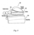
- tissue treatment area 10 is shown.
- Tissue treatment area 10 is illustratively shown to include the following tissue components: a prostate 11 having a prostatic capsule 12, urethra 14, seminal vesicles 16, and a rectum 17 having a rectal wall 18.
- NVB neuro-vascular bundles
- the NVB's are critical in the ability of the patient to achieve erections. As such, damage to NVB 20 may result in the patient experiencing impotence, erectile dysfunction and incontinence.
- the location of the NVB 20 can be determined based on the locations of the vascular component of the NVB 20.
- the vascular component of the NVB 20, if healthy, includes blood flowing through respective blood vessels. Such blood flow may be detected with Doppler ultrasound imaging. Doppler ultrasound imaging techniques are well known in the art. Doppler ultrasound imaging may also be used to detect early stage prostate cancer in the patient due to the fact that early stage prostate cancer forms neo-vascularization.
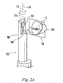
- HIFU system 100 includes a probe 102 having a transducer member 104, a positioning member 106, a controller 108 operably coupled to probe 102 and the positioning member 106, a user input device 110 (such as keyboard, trackball, mouse, and/or touch screen), and a display 112.
- Probe 102 is operably connected to controller 108 through positioning member 106.
- Positioning member 106 is configured to linearly position transducer member 104 along line 114 and to angularly position transducer member 104 in directions 115, 116.
- controller 108 includes software 109 located in memory 111.
- Software 109 controls the operation of HIFU System 100 including the imaging of the tissue treatment area 10, the automatic planning of a proposed HIFU treatment, and the provision of HIFU Therapy during treatment.
- Transducer member 104 is positioned generally proximate to a region of tissue treatment area 10. In the case of the prostate, transducer 104 is positioned generally proximate to the prostate by the transrectal insertion of probe 102. Transducer member 104 is moved by positioning member 106 and controlled by controller 108 to provide imaging of at least a portion of the tissue in tissue treatment area 10 and to provide HIFU therapy to portions of the tissue within tissue treatment area 10.
- prostatic capsule 12, urethra 14, seminal vesicles 16, rectal wall 18, are NVB 20 are included in the portions of tissue imaged.
- HIFU system 100 may operate in an imaging mode wherein at least a portion of the tissue within tissue treatment area 10 may be imaged and in a therapy mode wherein HIFU therapy is provided to portions of the tissue within tissue treatment area 10.
- transducer member 104 is a single crystal two element transducer. A central element is used for imaging and a surrounding element is used for HIFU Therapy. In one embodiment, both elements work at 4 MHz. In another embodiment, the HIFU Therapy element operates at 4 MHz and the imaging element operates at 5-7 MHz.
- An exemplary transducer is disclosed in U.S. Patent No. 5,117,832 . However, one skilled in the art will appreciate that various transducer configurations may be implemented. In a one embodiment, transducer 104 is capable of providing imaging of at least a portion of the tissue within tissue treatment area 10 and of providing HIFU therapy to at least a portion of the tissue within tissue treatment area 10.
- transducer geometries having a single focus or multiple foci and associated controls may be used including transducers which are phased arrays, such as the transducers disclosed in pending U.S. Patent Application Serial No. 11/070,371, filed on March 2,2005 ("'371 Application").
- '371 Application As explained in the '371 Application, at least one transducer disclosed therein has a scanning aperture. As such, the disclosed transducer does not require positioning member 106 to translate the disclosed transducer in direction 114 during imaging and treatment.
- transducer 104 is capable of providing imaging information about the tissue in tissue treatment area 10 (such as a plurality of two-dimensional images), to provide HIFU therapy to at least a portion of the tissue in the tissue treatment area 10, and to provide Doppler imaging of at least a portion of the tissue in the tissue treatment area 10.
- transducer 104 is a single transducer having at least two transducer elements.
- transducer 104 is comprised of multiple transducers, each having one or more elements.
- Probe 102 is configured to be positioned next to the rectal wall 18 of a patient and to be fixably secured relative to the patient during a treatment procedure as described below. By fixing the location of probe 102 relative to the patient it is possible to repeatably locate transducer member 104 relative to the patient with positioning member 106. Such repeatability is important due to requirements of the treatment procedure to first determine the location of various tissue components within the tissue treatment area 10 with ultrasound imaging, the determination of potential treatment zones or treatment sites based on the identified location information, and the subsequent placement of transducer member 104 to provide HIFU Therapy to locations in the tissue treatment area 10 corresponding to the treatment zones or treatment sites. Additional details of suitable ultrasound systems and methods of using high intensity focused ultrasound to treat tissue are disclosed in US Patent No. 5,762,066 ; U.S.
- HIFU system 120 includes a console 122 which houses or supports a controller (not shown), such as a processor and associated software; a printer 124 which provides hard copy images of tissue 10 and/or reports; a user input device 126 such as a keyboard, trackball, and/or mouse; and a display 128 for displaying images of tissue 10 and software options to a user, such as a color display. Further shown is a probe 130 which includes a transducer member (not shown), and a positioning member (not shown).
- the Sonablate® 500 HIFU System further includes an articulated probe arm (not shown) which is attached to the operating room bed or surgical table (not shown).
- the articulated probe arm orients and supports probe 130.
- the Sonablate® 500 HIFU System further includes a chiller (not shown) which provides a water bath for the transducer member of probe 130 to remove heat from the transducer member during the provision of HIFU Therapy.
- the software and/or hardware of the Sonablate® 500 HIFU System is modified to incorporate the functioning of the present invention.
- Ultrasound system 100 is configured to use Doppler imaging techniques to identify the location of rapidly moving bodies in the tissue treatment area 10, such as blood flow associated with NVB 20. As explained below, such location information related to the location of blood flow is used in determining the location of various tissue components, such as NVB 20 so that these zones may be excluded from the treatment plan.
- the treatment plan is based on an automatically generated proposed treatment plan which takes into account the location of the NVB to exclude the NVB from the treatment plan.
- Controller 108 includes an imaging module 150 which controls the imaging of the tissue treatment area 10, a system control module 156 which controls various aspects of the system such as transducer positioning 158 and the provision of HIFU Therapy 160, and a treatment planning module 162 which develops a proposed treatment plan for treating the tissue in the tissue treatment area 10.
- Imaging module 150 includes the imaging of the tissue treatment area by a plurality of two-dimensional images such as sector and linear images, as represented by 2-D imaging 152. Imaging module 150, as discussed herein, further includes the use of Doppler Imaging to determine the location(s) of blood flow in the tissue treatment area, as represented by Doppler Imaging 154.
- Treatment planning module 162 generates a proposed treatment plan for treating the tissue in the tissue treatment area 10.
- Treatment planning module 162 includes a modeling component 164 which models tissue components in the tissue treatment area 10, a detection of exclusion zones component 166 which determines the location of exclusion zone as discussed herein, a transducer/treatment parameters component 168 which provides input on the system characteristics, and a user interaction component 170 which provides information about a proposed treatment plan to a user and receives modifications from a user.
- the Doppler System 154 of controller 108 is discussed below in connection with Figs. 4A-C .
- the Doppler system may be implemented as software and as a combination of software and hardware. Further, a Pulsed-Wave (PW) Doppler system and a Color Flow Imaging (CFI) Doppler system are disclosed.
- PW Pulsed-Wave
- CFI Color Flow Imaging
- System 200 includes a digital micro-controller 202 which provides a signal to an analog transmitter 204 instructing the transmitter to transmit an ultrasound signal with transducer 104.
- transducer 104 uses a single element for Doppler imaging.
- the transmitted signal is about 4 microseconds ( ⁇ sec) in duration and at a frequency of about 4 MHz.
- Echo signals (reflected from the tissue treatment area) are received by transducer 104 subsequent to the transmitted signal and are provided to an analog receiver 206.
- Receiver 206 passes the received echo signals onto a mixer 208 which mixes the analog echo signal with a reference signal (indicated by line 210) from micro-controller 202.
- the reference signal has the same frequency as the transmitted signal and is used to remove this high frequency carrier signal, from the received echo signal; thereby leaving the low frequency Doppler signal.
- the low frequency Doppler signal is between about 400 Hz to about 2 kHz.
- the resultant Doppler signal is then provided to a series of gates 212a, 212b, 212c, 212d.
- the particular gate 212 that receives the resultant Doppler signal is controlled by micro-controller 202 as represented by lines 214a, 214b, 214c, 214d.
- the Doppler signal is sampled and held, as illustrated by block 216a, 216b, 216c, 216d.
- the resultant sampled Doppler signal is filtered with a bandpass filter 218a, 218b, 218c, 218d.
- the bandpass filter is configured to pass frequencies in the range of about 400 Hz to about 2 kHz.
- Each gate 212 is activated by microcontroller 202 for a specified period of time. For example, for an echo signal whose useful duration (the useful duration in one embodiment being the time frame generally equal to expected depth of the tissue being imaged) is n ⁇ sec, gate 212a is activated from 0 to n/4 ⁇ sec, gate 212b is activated from n/4 ⁇ sec to n/2 ⁇ sec, gate 212c is activated from n/2 ⁇ sec to 3n/4 ⁇ sec, and gate 212d is active from 3n/4 ⁇ sec to n ⁇ sec. If only a single gate 212 was used, then four separate transmitted and received echo pairs would need to be used to cover the same depth of tissue as the four gate system 200 illustrated.
- more of the echo signal received by transducer 104 may be processed for the presence of Doppler information as a function of depth at the same time and hence more depth of the tissue treatment area 10 may be reviewed with a given transmitted signal and received echo pair. This reduces the amount of time needed to obtain Doppler information about the tissue treatment area 10.
- microcontroller 202, transmitter 204, receiver 206, mixer 208, sampling/hold 216 and filter 218 are all included on a circuit board such as an audio board.
- Each gate 212 contained on the circuit board having an output 220.
- This output 220 provides the filtered signal to one of a speaker (not shown) for auditory detection of the presence of blood flow and controller 108 for further processing.
- controller 108 processes the output signal by root mean square (RMS) techniques, as represented by block 222, for the presence of blood flow (as indicated by the shift in frequency due to the Doppler effect).
- RMS processing 222 for the presence of blood flow is well known in the art and may be carried out by hardware processing and/or software processing.
- FFT Fast Fourier Transform
- spectrum integration or power spectrum
- FFT typically has a higher Signal to Noise Ratio (SNR) than RMS processing.
- the microcontroller 202 manipulates the frequency and repetition rate of the Doppler transmit pulse, controls the width and depth of the multiple receiving gates 212 for analog receiving processing, and generates the reference signal 210 for demodulating the Doppler echo in analog transmit/receive circuit section.
- the multiple gates 212 of system 200 shown in Fig. 4A are replaced by software processing wherein the received echo signal is digitized and stored in memory 111 associated with controller 108.
- Software 109 then processes the data to separate the time signal by different gate locations. This approach requires a 16 bit or higher resolution analog to digital converter and more memory and processing capability than the above illustrated system 200.
- System 200 described in connection with Fig. 4A is able to detect the presence of blood flow. However, system 200 is not able to distinguish the direction of blood flow. As illustrated in Fig. 4B , system 200 may be modified to produce system 260 which is capable of determining the direction of blood flow. System 260 unlike system 200 has two gates 242a and 242b, each having two channels 244a, 244b and 244c, 244d. However, more gates 242 may be added to system 260 such that it has an equal number of gates 242 as system 200.
- System 260 has two reference signals 250a and 250b that are provided to mixer 208.
- Reference signals 250a, 250b are similar to reference signal 210 in that they are at the carrier frequency (in one example about 4 MHz), but reference signal 250b is 90° out of phase from reference signal 250a.
- Each gate 242 of system 240 samples the mixed received echo signal and 0° reference signal on a first channel (I channel) 244a and 244c, respectively, and the mixed received echo signal and 90° reference signal on a second channel (Q channel) 244b and 244d, respectively. The combination of these two channels are then processed by well known color flow imaging techniques indicated by color flow imaging routine (CFI) 262.
- CFI requires two channels 244 for each gate 242, both the I and Q channels.
- the multiple gate system 260 may be carried out in software, system 280, wherein the CFI Processing 262 further includes a cross-correlation function to detect the time shift of gated echoes in successive RF signal.
- the hardware does not require mixer 208, sample/hold circuit 216, and filters 218. All data processing is in the digital domain. However, a low signal-to-noise ration processed in the digital domain with digitization errors may affect the results of flow velocity estimation.
- the location information obtained by HIFU System 100, sector and linear images and Doppler information, is used to provide on display 112 a representation of the tissue treatment area 10.
- the representation of the tissue treatment area 10 includes one or more two-dimensional views of the tissue treatment area, such as one or more sector views and one or more linear views.
- traditional 2-D ultrasound imaging is used to generate sectors views, such as a sector view in sector plane 190 in Fig. 2A and linear views, such as a linear view in linear plane 192 in Fig. 2A .
- the displayed view preferably a sector view, provides a representation or icon to indicate the location of blood flow as determined by using Doppler imaging techniques.
- multiple sector views 200 are arranged on display 112 so that the physician can see multiple sectors of the tissue treatment area 10.
- both sector views and linear views are arranged on display 112 so that the physician may see multiple sectors of the tissue treatment area 10.
- an automatically generated proposed treatment plan, or at least a portion of the proposed treatment plan may be displayed as well.
- the icon or representation of the location of blood flow is shown as an abstracted representation, such as box 602 in Fig. 10A .
- This provides a general indication of the location of blood flow.
- the icon or representation 602 may be colored to offset itself from the background.
- the icon or representation of the location of blood flow is one or more color pixels.
- the color pixels are typically colored to offset themselves from the background, such as red or blue.
- only the pixels either a two-dimensional pixel for a sector view or a three-dimensional pixel for a volume view
- the brightness, color, or other indicia of the representation is an indication of the amount or velocity of blood flow or the direction of the blood flow.
- the representation or icon may be brighter to indicate higher volumes or velocities of blood flow.
- HIFU System 100 is configured to provide three-dimensional imaging of the tissue treatment area 10.
- HIFU System 100 displays a volume image of the tissue treatment area 10, the volume image being generated from multiple 2-D images (see Fig. 12 for example).
- HIFU System 100 generates a three-dimensional model representation of the location of the tissue components of tissue treatment area 10. Details of a preferred method to generate three-dimensional model of tissue components in the tissue treatment area 10 is provided herein.
- tissue components expected to be located in the tissue treatment area 10 corresponds to the area surrounding prostate 11
- expected tissue components include rectal wall 18, urethra 14, prostatic capsule 12, seminal vesicles 16, and/or neuro-vascular bundles ("NVB") 20.
- the three-dimensional representation of one or more tissue components may be manipulated through input from user input device 110 to change the orientation of the respective three-dimensional representation. In this way a physician may virtually review all sides of the representations of the tissue components of the tissue treatment area 10.
- the location information determined by the Doppler imaging, 2-D imaging and/or the 3-D imaging with HIFU System 100 in a preferred embodiment is utilized to determine an appropriate treatment procedure for treating at least a portion of the tissue in the tissue treatment area 10 with HIFU Therapy.
- imaging and treatment method 300 is carried by controller 108 of HIFU System 100.
- imaging and treatment method 300 is embodied in software 109 that is loaded onto memory 111 accessible by controller 108.
- HIFU System 100 based on ultrasound imaging data collected by transducer member 104 determines the location of tissue components located within the tissue treatment area 10.
- HIFU System 100 uses the 3-D modeling techniques discussed herein to determine and model the location of the tissue components, such as rectal wall 18, urethra 14, and prostatic capsule 12.
- HIFU System 100 based on Doppler imaging data collected by transducer member 104 determines the location, if any, of blood flow in the tissue treatment area 10.
- HIFU System 100 uses the 3-D modeling techniques discussed herein to determine and model the location of the tissue components including blood flow.
- the location of tissue components is determined using both 2-D and/or 3-D imaging and Doppler imaging.
- HIFU System 100 generates a three-dimensional model of the tissue components in the tissue treatment area including the vascular components which include blood flow.
- the three-dimensional model is displayed on display 112.
- HIFU System 100 displays representations or indicia of proposed treatment sites based on the identified location information of the tissue components and/or the location of blood flow in tissue treatment area 10.
- HIFU System 100 is configured to identify various treatment zones corresponding to the location of prostatic capsule 12.
- the HIFU System 100 automatically excludes locations which overlap with other tissue components from being suggested or proposed treatment zones, such as locations corresponding to NVB 20 (including blood flow).
- the HIFU System 100 includes locations which overlap with other tissue components as being suggested treatment zones, such as locations corresponding to the neuro-vascular bundles 20.
- the representations or treatment indicia which correspond to these overlapping locations include an indicia or icon differing from the other suggested treatment zones to alert the physician to the location of overlapping tissue (such as a differing color).
- HIFU System 100 receives input from user input device 110 related to the suggested or proposed treatment zones to add or to exclude.
- the physician may decide to proceed with treatment in the area of the NVB 20 to more fully treat the potential diseased tissue and/or because of the patient's wishes. It is important to highlight that the addition of Doppler imaging permits identifying the location of NVB 20, a tissue typically not resolvable by traditional 2-D imaging techniques. As such, the Doppler imaging permits the physician to have location information on the location of the NVB 20 and hence to permit the selective treatment of tissue areas based on the potential damage to the NVB 20.
- HIFU System 100 focuses high intensity ultrasound energy at the locations in the tissue treatment area corresponding to the treatment zones.
- the high intensity focused ultrasound is an effective tool for selectively destroying diseased tissue surrounded by otherwise healthy tissue in a minimally invasive manner.
- HIFU Therapy requires the emission of a continuous wave ("CW") for a sustained period of time with sufficient intensities to ablate the target tissue at the desired location, the focus of transducer 104.
- CW continuous wave
- the Sonablate ® 500 HIFU system typically is set to provide a CW from its associated transducer for about three seconds resulting in ablation of the target tissue at the focus of the transducer. This time period can be increased or decreased depending on the desired lesion size or the desired thermal dose.
- the transducer member 104 of ultrasound system 100 must be capable of being repeatably positioned relative to tissue treatment area in order for the above described method to be effectively carried out. This is because registration is needed between the actual locations of the tissue components and the locations of the suggested treatment zones which are based on the location information derived from the information gathered by transducer member 104. If the transducer member 104 is not capable of being repeatably positioned than there can be no assurance that the location of a treatment zone truly corresponds to the correct location in the tissue treatment area 10.
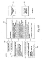
- FIG. 6A another exemplary method 400 of treating tissue treatment area 10 containing a plurality of tissue components is provided.
- the exemplary method 400 is tailored to a tissue treatment area including prostate 11 and related tissue components.
- the exemplary method 400 may be used with other tissue treatment areas having other tissue components.
- the patient and system 100 are setup for the treatment of tissue treatment area 10.
- the patient and the prostate gland are immobilized.
- Transducer 104 is positioned proximate to prostate 11 by the transrectal insertion of probe 102 containing transducer 1.04.
- the patient is treated under general anesthesia.
- Probe 102 is held in place by coupling the articulated arm (not shown) to the surgical table (not shown) on which the patient is situated.
- images of the tissue treatment area are taken with transducer 104 prior to coupling the arm to the surgical table to verify that the tissue treatment area 10 being imaged with transducer 104 includes the tissue components desired.
- tissue treatment area 10 and hence the patient should remain in the same position relative to probe 102 during the procedure.
- tissue treatment area 10 is imaged and these images are subsequently used to determine the portions of the tissue treatment area 10 which are to receive HIFU Therapy.
- transducer 104 may be reliably positioned to provide HIFU Therapy to the correct portions of tissue treatment area 10.
- it is not possible to accurately position transducer 104 relative to tissue treatment area 10 and the patient or probe will have to be repositioried or re-aligned prior to treatment planning and HIFU Therapy.
- patient movement is detected by measuring the distance from transducer 104 to rectal wall 18 and to provide an indication of patient movement if that distance changes above a threshold amount.
- a plurality of sector images and linear images are taken of the tissue treatment area prior to the commencement of treatment with HIFU therapy.
- a set of one linear and one sector image are generated (post-lesion images) and displayed with display device 112 along with the associated reference images (stored pre-treatment images) for the same site.
- the distance from transducer 102 to rectal wall 18 in the pre-treatment images and post-lesion images are compared to provide one method of detecting patient movement.
- three dimensional ultrasound images or volume images of the tissue treatment area are obtained.
- the volume images are generated based on two-dimensional images of the tissue treatment area.
- a plurality of sector images and a plurality of linear images are obtained.
- an exemplary sector image plane 190 is shown and an exemplary linear image plane 192 is shown.
- an origin 194 of a common probe space 196 is also shown. The origin is defined by the center of transducer 104 when it is at its lowest position of translation in direction 114 (or the lower most aperture of a scanning aperture transducer) and when transducer 104 is pointing straight out the probe-tip.
- a plurality of sector images and linear images are obtained. These sector and/or linear images are used to calculate a volume ultrasound image of the tissue treatment area.
- the volume image is created by stacking scan-converted two-dimensional sector images. In one example, about 160 sector images, are acquired. Each sector image has 250x357 pixels. The pixel size both in the sector plane and between planes is 0.25 mm, forming cubic voxels (three-dimensional pixels) for distortion-free reconstruction and display. This forms the fundamental 3D prostate imaging dataset. This dataset spans a volume of 40 mm (long (160 pixels)) x 61 mm (height (250 pixels)) x 110° (width (357 pixels)).
- Each sector image is inserted into a 3D array in memory 111 for transfer to a rendering board which is incorporated into controller 108.
- the sector images are equally spaced between the proximal and distal ends of the prostatic capsule, one sector image passing approximately through the middle of the capsule; similarly, the linear images are equally spaced between the lateral limits of the capsule, one linear image passing approximately through the middle of the prostatic capsule.
- Controller 108 reconstructs and displays a 3D or volume rendered view of the ultrasound data and treatment zones on display device 112.
- An exemplary rendering board is VolumePro TM 500 or VolumePro TM 1000 available from TeraRecon located at 2955 Campus Drive, Suite 325, San Mateo, CA 94403.
- different density tissue in the volume image may be displayed in different colors with the VolumePro TM 1000.
- An exemplary volume rendering is shown in Fig. 12 . Referring to Fig. 12 , the prostate, rectal wall, and fat layer are visible. Further, shown in Fig. 12 , are proposed treatment zones for HIFU Therapy. The formation of these proposed treatment zones is discussed herein.
- the rendered image via input from user input device 110 may be rotated, may be scaled, and may have different image attributes, such as transparency.
- the physician or user is able to view the entire prostate 11 on the screen at one time for pre-treatment and/or post-treatment diagnosis purposes. Further, the volume imaging allows for verification of the planned treatment.
- the user may select to view the tissue treatment area as the volume ultrasound data shown in Fig. 12 or in multiple two-dimensional images, such as a plurality of sector images which have traditionally been used for treatment planning with the Sonablate® 500 HIFU system, such as in Fig. 11 and Fig. 11A .
- the volume image includes interpolated points between the various sector images and/or linear images to enhance the rendered view of the tissue treatment area and/or to reduce the number of sector and/or linear images required.
- bilinear interpolation which ignores data from adjacent planes, is used.
- trilinear interpolation is used.
- a tri-cubic spline is used.
- the volume image data in one embodiment, is further refined before it is presented to the physician or user for review.
- One exemplary refinement is adjustments to the histogram of the data to manipulate the contrast and/or brightness of the volume ultrasound data.
- the histogram data is set to an "S-shaped" map.
- Another exemplary refinement is an enhancement of boundaries in the volume data. This enhancement provides assistance to the user in tracing the prostatic capsule 12 and other tissue components in the tracing step, as represented by block 406, below. Further, this enhancement aids controller 108 in identifying the locations of various tissue components, such as rectal wall 18.
- tissue components are identified based on the volume image data of the tissue treatment area. At least some of the tissue components, such as rectal wall 18 are identified automatically by controller 108. The rectal wall boundary is automatically detected by simple edge-detection algorithms. In one embodiment, some of the tissue components are identified and located through interaction between a user and the image data, either presented as volume data or as one or more 2-D images. One exemplary tissue component located through user interaction is prostatic capsule 12.
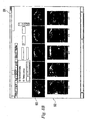
- the user is presented multiple sector images 500 and linear images 502 on display 112.
- the user then traces or otherwise marks the requested components in one or more of the sector images and/or one or more of the linear images.
- the user manually traces the contour of capsule 12 in at least one sector image (illustratively image 500A in Fig. 8A ) and manually traces the contour of the capsule 12 at least one linear image.
- the user is given up to five sector images and five linear images in which to trace the capsule (see Fig. 8B ).
- the user traces at least five sector images and at least three linear images.
- the user marks the center of urethra 14 in each sector image that the user traces capsule 12. In one embodiment, the user traces one or more of urethra 14, seminal vesicles 16, and rectal wall 18, in addition to the prostatic capsule 12.
- the user defines the tracing of a boundary by clicking on points to define a rubber-banding B-spline fit on slices in any or all of the multiple orthographic views.
- the user will trace the views near mid-gland and at equally spaced intervals to encourage more uniformly spaced data for unbiased geometric model fits.
- the user is to mark the center of urethra 14 in each sector image 500.
- a sonolucent catheter is inserted into urethra 14 during the imaging process to make urethra 16 easier to identify in sector images 500.
- the catheter is removed prior to HIFU Therapy being administered to the tissue treatment area.
- the trace data for capsule 12 and urethra 16 are recorded as xyz-Cartesian coordinate data in the probe reference space 196 and written to memory 111 for use in modeling.
- FIG. 8A and 8B An exemplary user interface for tracing or otherwise marking tissue components is shown in Figs. 8A and 8B .
- the interface 506 of Fig. 8B provides a plurality of sector views 500 and linear views 502 which the user may select to trace boundaries thereto.
- the interface 508 of Fig. 8A is a trace mode screen wherein the user is presented with an image, illustratively image 500A, on which the user traces or marks appropriate portions of the images 500A.
- the user is able to select a tissue component to be marked from the plurality of tissue components listed at the bottom of the screen by selecting the corresponding textual button (capsule 510A, rectal wall 510B, seminal vesicles 510C, 510D, urethra 510C, and NVB 510F) or by selecting the corresponding iconic button (capsule 510G, urethra 510H, and seminal vesicles 510I). Further, as shown in Fig. 8A , the user is able to mark components in a point mode 512 and a trace mode 514.
- the user places points to define the outline of the component (illustratively points 516a-n to define the outline of capsule 12) or the center of the component (in the case of the urethra). Controller 108 then uses the points to generate traces, such as b-spline traces.
- traces such as b-spline traces.
- the user outlines the region by tracing a closed line (i.e. by holding down a mouse button during the trace). The controller 108 then takes this information to generate a smoother trace.
- the user may desire to exclude certain regions of the tissue from treatment. Some of these regions are automatically identified by the system, such as NVB 20 as explained herein. Other regions are identified by the user. One method of identifying these region is to trace or otherwise mark these regions similar to the tracing of tissue components. For instance, the user may select an exclude button 518 and provide trace data for regions that the system should exclude from treatment.
- One example may be ejaculatory ducts which are typically not detected by ultrasound, but their location may be inferred by the user from other structures.
- the trace data, other marking data (urethra centers), and automatically located boundaries (such as the rectal wall 18) are used to develop three dimensional models of at least some of the tissue components in the tissue treatment area 10, as represented by block 408.
- Fig. 9 the following exemplary models are shown: prostatic capsule 530, urethra 532, rectal wall 534, and seminal vesicle 536.
- prostatic capsule 530 prostatic capsule 530
- urethra 532 the following exemplary models are shown: prostatic capsule 530, urethra 532, rectal wall 534, and seminal vesicle 536.
- These three-dimensional models are used by system 100 in the automatic generation of a proposed treatment plan, as discussed herein, to assist in the location of other tissue components (such as NVB), to remove clutter from the volume ultrasound data, and/or to provide a visual representation of tissue treatment area 10.
- Many different techniques may be used to model the tissue components in the tissue treatment area. Exemplary methods of modeling the pro
- R constant radius
- R 2.5 mm
- This radius size should envelope almost all real urethras.
- the path h(t) is found by performing a least squares fit to the centers of the urethra identified or marked by the user in the various sector images 500.
- the radius function R(t) is determined by performing a least squares fit to the radii of the circles that best fit rectal wall 18 in each sector image 500.
- the left- and right-seminal vesicles are modeled as unions of overlapping spheres of varying radii fit to user-defined boundaries. In order to mark these components the user traces their boundaries, similar to the tracing for the prostatic capsule.
- Prostatic capsule 12 may be modeled by various techniques. In one embodiment, prostatic capsule may be modeled as approximating a sphere. In a further embodiment, prostatic capsule 12 may be modeled as an ellipsoid. In another embodiment, prostatic capsule model 530 is generated by modeling prostatic capsule 12 with Fourier ellipsoids. A Fourier ellipsoid is obtained by replacing the (elliptical) cross-sections normal to the major axis of a standard ellipsoid by curves that have a more general Fourier description. This permits the resultant surfaces to have more complex spatially-varying geometric features than standard ellipsoids. This is particularly advantageous when dealing with diseased and/or clipped prostatic capsules whose shape may be irregular.
- the shape of prostatic capsule 12 may be determined along with other parameters such as the volume of prostatic capsule 12, the surface area of prostatic capsule 12, and the relative location of points within the treatment area as being either inside or outside of prostatic capsule 12 or on the surface of prostatic capsule 12.
- the surfaces for the prostatic capsule model 530 are used to generate a solid volume model of the prostate. Additional details concerning the modeling of the prostatic capsule are provided in the APPENDIX.
- Doppler imaging is used to determine and/or assist in determining the location of various tissue components within the tissue treatment area 10.
- Doppler imaging is used to locate NVB 20 so that these nerves may be excluded from treatment.
- NVB 20 resides close to the surface of prostatic capsule 12 and are densely vascularized.
- Treatment of NVB 20 with HIFU Therapy may result in impotency, erectile dysfunction, and/or incontinence.
- the user may still decide to treat these regions if the user feels that cancer is in close proximity to NVB 20.
- Doppler imaging data is generated with transducer 104 separate from the generation of the two-dimensional sector and linear images (discussed in relation to block 404).
- the two-dimensional sector and linear images are obtained prior to the Doppler information.
- the system uses the location of the shape models to determine portion of the tissue treatment area 10 to scan during the Doppler imaging. This is because NVB 20 are typically in a given spatial relationship to other tissue components such as prostatic capsule 12.
- either the two-dimensional or the volume ultrasound data may provide the location of various tissue components and hence be used to determine the portions of the tissue treatment area to scan during Doppler imaging. As stated herein it is well known in the art to use Doppler imaging techniques to determine the location of blood flow.
- Portions of tissue treatment area 10 exhibiting blood flow may be displayed with display device 112 with a special representation or icon.
- the blood flow may be shown on two-dimensional sector images 600A as icons 602. Further, the blood flow may be shown as an overlay on top of the volume ultrasound image and/or tissue component models via a color-map (see Fig. 13 , blood flow icons 702).
- the color map in one embodiment color codes the displayed representation or icon to provide an indication of the amount of blood flow present.
- the display of the blood flow enables the physician or user to visualize the position of the blood flow and its relative position to other tissue components, such as the prostatic capsule (prostatic capsule model 530 in Fig. 13 ). Further, the physician or user, based on the amount of blood flow present, may be provided an indication of the health of NVB and whether NVB 20 is healthily enough to warrant exclusion from HIFU treatment.
- Doppler imaging is used to detect very small prostate cancer sites. In the early stages of cancer growth the cells form neo-vascularization. Therefore, Doppler imaging may be used to determine the location of these sites. Unlike the case of NVB, these sites are targeted for treatment with HIFU Therapy. In one embodiment, an ultrasound contrast agent is used to enhance the detection of these sites and/or NVB 20.
- the Doppler imaging not only provides a visual cue to the user, but it also is one of a plurality of input to an automatic treatment planning module 416 which develops a proposed HIFU treatment plan for review by a user.
- the Sonablate® 500 HIFU system requires a physician or user to define treatment zones on up to 15 different ultrasound images that span the entire prostate.
- HIFU System 100 is configured to generate a proposed HIFU treatment plan consisting of a plurality of treatment zones without the need of input from the user except for desired modifications to the proposed HIFU treatment plan made by the user and the marking of tissue components as discussed herein in connection with block 408.
- an automatic proposed treatment plan is developed to treat portions of tissue treatment area 10.
- the automatic treatment module 416 uses the following five categories of inputs in developing the automatic proposed treatment plan: shape models 450 generated during step 408, location information about the NVB 452 generated during step 410, transducer parameters 454, Inclusion/Exclusion information 456, and treatment parameters 458. Shape models and NVB location information has been discussed above.
- Transducer parameters 454 play an important role in the development of an automatic proposed treatment plan.
- Exemplary transducer parameters 454 include focal length of the transducer, the size of the transducer, and the degree of rotation by the transducer (in one example the transducer may be rotated 110° and still transmit and receive ultrasound energy through a window in the probe housing).
- the size and shape of a single thermal lesion produced as a result of HIFU Therapy to a given treatment site is governed by the geometry of the transducer 104 within transrectal probe 102, the duty cycle and repetition rate of the applied acoustic signal, the acoustic properties of intervening tissue types, and the acoustic power delivered at the focus. As explained herein, the present application is not limited to a particular type of transducer 104.
- transducer 104 is a spherically focused, truncated spherical shell transducer with a 30 mm diameter aperture and having two transducer faces, one face having a 30 mm focal length operating at 4 MHz and about 30 W of total acoustic power and the other face having a 40 mm focal length operating at 4 MHz and about 37 W of total acoustic power.
- This is similar to the transducers traditionally used with the Sonablate® 500 HIFU System.
- Ultrasound exposures for a given HIFU Therapy are assumed to be about 3 sec. HIFU "ON” followed by about 6 sec. HIFU "OFF" duty cycle.
- the dimensions of a single thermal lesion are generally ellipsoidal, approximately 3 mm in width, and approximately 10 mm in length. Further, the thermal lesion is located near the geometric focus of transducer 104. In addition, these elliptical thermal lesions when spaced about 2-3 mm apart tend to merge via thermal diffusion to form a larger necrotic volume. In one embodiment, about 1000 thermal lesions are needed to treat an average human prostate.
- the acoustic properties of the intervening tissues are patient specific and temperature dependent. However, the variation in these properties do not substantially change the initial deposition of an isolated thermal lesion from that predicted by an elementary lesion.
- the size and shape of a thermal lesion is mainly controlled by the electrical power applied to transducer 104 and the geometry of the transducer, and its subsequent conversion of electrical power to acoustical power.
- transducer 104 By varying the focal length of transducer 104, such as with a phased-array transducer, and/or varying the electrical power applied to transducer 104 the size and location of a resultant thermal lesion may be controlled.
- a larger number of low power thermal lesions may be planned compared to other portions of the tissue treatment area 10 such as in the main portion of the prostatic capsule 12. Therefore, detailed treatment plans having pre-defined control of the HIFU dosage (i.e. intensity times exposure time) make it possible to shape thermal lesion patterns (like sculpturing) to increase efficacy and reduce side effects, especially when treating close to rectal wall 18.
- these detailed proposed treatment plans may be initially automatically developed and provided to physicians or users for review without requiring the physician to designate treatment sites or zones.
- a lesion library 113 is created wherein lesion size is categorized based on one or more parameters, such as focal length of transducer 104, excitation energy of transducer 104 , HIFU on-time of transducer 104. As such, if the automatic treatment plan module 416 requires a small size lesion, one or more ways of generating such a lesion may be determined based on lesion library 113.
- lesion library 113 is based on in-vivo observations of the size of lesions produced with known parameters, is based on simulated lesions, and/or a combination thereof.
- simulation software based on solving the transient bio-heat transfer equation (BHTE), as is well known in the art, is used to simulate various thermal lesions and hence to populate the respective lesion library 113.
- BHTE transient bio-heat transfer equation
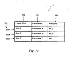
- Lesion library 113 includes a plurality of exemplary lesions 800, illustratively three 800A-C, which may be used by the automatic treatment module 416 to develop a proposed treatment plan as explained herein.
- a lesion size 802 is provided for each lesion 800.
- Lesion size 802 provides an indication of the expected size of a lesion produced during HIFU Therapy and is based on either in-vivo observations or simulations.
- associated parameters 804 are provided for each lesion 800.
- Parameters 804 are the parameters required to produce the respective lesion 800 and may include transducer, focal length, center frequency of CW, HIFU ON-time, HIFU OFF-time, transducer aperture, power levels, and water standoff distance (the distance between the transducer face and the rectal wall. This distance influences the ultimate size of a lesion as the ultrasound wave is not appreciably attenuated while traveling through water. Thus, for a large water standoff (required to treat close to the rectal wall), larger lesions are generated compared to a small water standoff (required to treat deep in the prostate) using the same power settings).
- a status 806 is provided. Status 806 provides an indication whether the respective lesion is available for selection by the automatic treatment module 416.
- lesion 800C examples wherein a particular lesion, illustratively lesion 800C, would not be available include situations wherein the transducer used to generate lesion 800C is not currently either coupled to the HIFU System or is otherwise unavailable.
- lesion 800C may be generated with a 35 mm focal length transducer and only a 30 mm focal length transducer and a 40 mm focal length transducer are available.
- Fig. 15 representative lesions 800D-S from lesion library 113 are shown.
- Each of lesions 800D-S are generated with a 40 mm focal length transducer with a 15 mm water standoff. Further, the differences between lesions 800D-S are generated by varying the power level provided at the proposed treatment site.
- the power level for each lesion 800D-S is provided in Fig. 15 along with a reference box 810 which is the same for each lesion 800D-S and has dimensions of 4X4X12 mm.
- a wide variety of lesion sizes may be generated.
- lesions 800D-S provide a wide variety of sizes that automatic treatment planning module 416 may select to develop the treatment plan for the tissue treatment region 10.
- various treatment parameters 458 may be defined as an input to the automatic treatment module 416. These treatment parameters are provided by the physician. In one embodiment, the physician is prompted to enter these parameters.
- One exemplary treatment parameter is margin. Margin is a percentage of a thermal lesion that may cross the boundary of the prostatic capsule into neighboring tissue.
- Another exemplary treatment parameter is Whole vs. Partial Ablation which relates to whether or not it is desired to treat the entire capsule or only a pre-determined zone, for example. In one embodiment, the predetermined zone may be traced by the physician similar to the capsule.
- Yet another treatment parameter is Lesion Overlap which relates to the percentage, if at all, the physician desires adjacent treatment sites to overlap each other. Other treatment parameters will be known to those skilled in the art.
- the automatically generated treatment plan significantly reduces the overall time required to develop a treatment plan to treat the diseased tissue in the tissue treatment area 10 and provides a valuable decision aid for the physician or user near critical structures, such as rectal wall 18 or NVB 20.
- an automatic treatment plan is generated with the automatic treatment planning module 416.
- the following discussion assumes that prostatic capsule 12 is to be treated for prostate cancer.
- the techniques discussed herein may be used to treat various types of diseased tissues in various tissue treatment areas 10, whether the tissue treatment area includes prostate 11 or not.
- the disclosed systems 100 and methods should not be limited to only the treatment of prostate 11 and diseases of the prostate.
- an exemplary algorithm 480 for automatic treatment planning module 416 is illustrated.
- proposed treatment sites proposed locations for thermal lesions
- the placement of the proposed treatment sites are restricted to portions of the tissue treatment area which were previously imaged during the acquisition of the two-dimensional images as discussed in connection with step 404.
- the center of each lesion is proposed to be located at a point in the tissue treatment area 10 which is imaged in at least one sector image and at least one linear image.
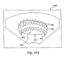
- Figs. 10A and 10B show exemplary indicia of proposed treatment sites 624 indicating the exemplary proposed treatment sites for a respective given sector image 600a and 600b.
- the size and shape of these exemplary indicia of the proposed treatment sites 624 are defined in the lesion library 113.
- the position of each indicia of proposed treatment sites 624 and hence the position of the resultant actual lesion is determined by the automatic treatment planning module 416.
- Fig. 10A illustrates generally two radial rows 620 and 622 of treatment sites (for a transducer having two focal lengths) and generally constant size thermal lesions or treatment sites within a given row of treatment sites 620, 622.
- 10B illustrates treatment sites 624 at at least three focal lengths and having varying sized lesions.
- smaller lesions are used to fill in portions near the edge of the prostatic capsule model 530, such as lesion 624a, and proximate to rectal wall 18, such as lesions 624b and 624c.
- the shown treatment sites do not illustrate the cumulative effect of heating the surrounding tissue.
- the spacing of the proposed lesions is chosen such that the individual lesions merge to form a larger lesion.
- larger lesion sizes are proposed where appropriate such as away from the rectal wall 18.
- the overall number of lesions may be reduced and hence the overall procedure time is reduced.
- the automatic treatment module 416 develops the proposed treatment sites as follows. First, the parameters provided by the physician are used to determine the area of the prostatic capsule and potentially areas proximate to the prostatic capsule to treat, such as the Margin parameter, and the desired spacing of the lesions, such as the Lesion Overlap parameter.
- the automatic treatment module 416 selects proposed lesions 800 from lesion library 113.
- the process is similar to filling ajar with rocks or blocks. First, a gross filling of the jar is completed by placing large rocks or blocks in the jar. Subsequently, a fine filling of the jar is completed by placing smaller rocks or blocks, even sand, in the jar. The smaller rocks or blocks fill in the spaces left open by the large rocks or blocks. In a similar way, the automatic treatment module 416 performs a gross filling of the area to be treated by filling the region with large size lesions 800 from lesion library 113.
- the automatic treatment module 416 performs a fine filling of the area to be treated by filling the open regions of the area with smaller lesions 800 from the lesion library 113.
- the automatic treatment module 416 also limits the portions of the area which are filled in the gross filling based on the tissue components in that region, such as near the rectal wall.
- lesion library 113 provides a plurality of different size blocks or "brushes" for the automatic treatment module 416 to use in planning a proposed HIFU treatment.
- the size of the blocks or brushes is dependent upon the system parameters including the transducer parameters.
- lesion library includes two brushes or blocks, one for a 40 mm transducer at a total acoustic power of 37 watts (W) and one for a 30 mm transducer at a total acoustic power of 20 W.
- lesion library has approximately 60 brushes which are generated by varying the total acoustic power (see Fig. 15 for example) for either the 40 mm transducer or the 30 mm transducer or both.
- the number of blocks or brushes may be increased.
- system 100 stores the required transducer parameters 454 and/or treatment parameters 458 for each proposed treatment site as represented by block 484. In one embodiment, these parameters are stored in the lesion library 113 along with the size of each lesion 800. Therefore, system 100 determines the required focal length of the transducer 104, the acoustic signal properties, and so forth. These parameters are used during the actual treatment of the tissue treatment area with HIFU Therapy.
- the automatic treatment module 416 also notifies the user of any additional setup requirements, such as repositioning probe 102 to treat various portions of prostate 11.
- the automatic treatment plan also automatically removes or deactivates proposed treatment sites based on their proximity to various tissue components such as rectal wall 18 and/or NVB 20. In one embodiment, these treatment sites are not even originally proposed to the physician. In another embodiment, these treatment sites are originally proposed and subsequently deactivated.
- the physician selects with user input device 110 the treatment indicia 624 corresponding to the treatment sites the physician desires to remove or deactivate. Further, the physician may select with user input device 110 treatment sites to add to the proposed treatment plan.
- the automatic treatment plan determines the order of treatment for the proposed treatment sites.
- this proposed order of treatment is determined prior to the proposed treatment plan being submitted to a physician or user for review.
- the order of treatment for the proposed treatment sites is determined after the physician or user has approved the proposed treatment plan, but prior to commencement of HIFU Therapy to any of the treatment sites.
- treatment sites in a given sector plane are treated prior to the treatment of treatment sites in another sector plane.
- treatment sites further from the transducer are treated prior to treatment sites proximal to the transducer (in the case of the prostate anterior to posterior treatment) due to the fact that HIFU therapy changes the properties of tissue in such a way that it prevents tissue ablation behind already ablated tissue.
- the proposed treatment plan is presented to the physician or user for review, as represented by block 422.
- One example of the presentation of the proposed treatment plane is shown in Fig. 11 .
- Fig. 11 a plurality of sector images 600a-i are shown with display device 112, each sector image 600 containing a portion of the proposed treatment sites, are displayed with the display device 112.
- a representation of one of the sector images is shown in Fig. 10A wherein an outline 531 of the shape model 530 for the prostatic capsule is shown, along with the proposed treatment sites shown as a plurality of treatment indicia 624 in rows 620, 622.
- icons or blood flow representations or indicia 602 representing regions of blood flow detected with the Doppler imaging, these regions being associated with NVB 20.
- the appearance of representation or indicia 602 indicating the regions of blood flow also include a color indication of the amount of blood flow so that the physician or user may make a determination as to the health of NVB 20.
- Ultrasound imaging data (not shown) for the given sector is also shown in Fig. 10A .
- the display shown in Fig. 11 in one embodiment includes buttons, slider controls, or other inputs which permit the selection of the number of sector images to be shown with display.
- Exemplary arrangements of sector images include 2x2, 3x3 (as shown), and 4x5 matrix display formats.
- Further controls may be included to select sector slice spacing (0.5, 1, 2, 3, and 3.8 mm), select size and define treatment zones at two different treatment depths, step through a sub-set of sector slices in higher resolution, and measurement functions (to provide measurements such as from a treatment site to a tissue component such as the urethra).
- Indicators showing the treatment zones, transducer focal limits, and rectal wall location may be enabled as graphic overlays on each slice (similar to the overlay for the prostatic capsule shown in Fig. 10A ).
- the physician may also select to view the indicia of the proposed treatment sites 624 as an overlay to the volume ultrasound data.
- An exemplary representation of such a display is shown in Fig. 12 .
- the physician also may select to view the proposed treatment sites 624 as an overlay to one or more of the shape models (such as prostatic capsule 530) and/or the volume ultrasound data.
- the surfaces of the shape models are rendered as thin, almost transparent, shells so the prostate anatomy (volume ultrasound data) and volume treatment zones can be clearly visualized for verification of the treatment plan.
- the user is able to interactively select which shape models are to be viewed.
- the system 100 limits the amount of volume ultrasound data to be displayed to portions of the tissue treatment area which are inside the prostatic capsule shape model and generally proximate to the outer surface of the prostatic capsule. An exemplary representation of such a display is shown in Fig. 13 .
- the physician may rotate images on display 112, zoom images on display 112, and slice the images on display 112 through a touch screen input device.
- the physician is further able with user input device 110 to select further regions of the treatment zone for inclusion in the proposed treatment or for exclusion from the proposed treatment.
- all of the physician's selections discussed herein are made through a touch screen interface of display 112 and additional input devices 110, such as a keyboard, as needed.
- the proposed treatment plan is approved, by input from the user (such as selecting a button to approve treatment).
- the proposed treatment plan is executed by the system once the order of treatment of the treatment sites has been determined, as represented by block 424.
- automatic treatment planning module 416 is not used or available.
- the physician develops a manual treatment plan, as represented by block 423.
- the manual treatment plan may be laid out by the physician on a plurality of two-dimensional images, such as sector images and/or linear images.
- the display and review function 422 may still be used to display the manually generated treatment plan and to review the treatment plan. All of the same viewing options are still available with the display of the manual treatment plan, as indicated by line 425 for the shape models and line 427 for the blood flow information.
- the physician may use the blood flow information and the shape models in the review of the manual treatment plan to determine if modifications are required.
Claims (15)
- Vorrichtung zum Behandeln eines Gewebebehandlungsbereichs mit mehreren Gewebekomponenten, wobei die Vorrichtung Folgendes umfasst: einen Wandler (104), der in Bezug auf den Gewebebehandlungsbereich (10) positioniert werden kann, wobei der Wandler (104) zum Emittieren von Ultraschallenergie konfiguriert ist, eine Steuerung (108), die mit dem Wandler (104) operativ gekoppelt ist, wobei die Steuerung (108) zum Betreiben des Wandlers (104) in einem Abbildungsmodus, in dem Bilder des Gewebes, Blutflussinformationen sowie dreidimensionale volumetrische Daten erhalten werden, und in einem Therapiemodus konfiguriert ist, in dem Teile des Gewebes in dem Gewebebehandlungsbereich (10) von dem Wandler (104) mit einer HIFU-(hochintensiver fokussierter Ultraschall)-Therapie behandelt werden, wobei die Steuerung (108) ferner zum automatischen Erzeugen eines vorgeschlagenen Behandlungsplans zum Durchführen von HIFU-Therapie für den Gewebebehandlungsbereich (10) konfiguriert ist, wobei der vorgeschlagene Behandlungsplan das Auswählen von mehreren Behandlungsstellen zum Durchführen von HIFU-Therapie beinhaltet, wobei die mehreren Behandlungsstellen des vorgeschlagenen Behandlungsplans zum Durchführen von HIFU-Therapie an einer ersten Gewebekomponente ausgewählt werden, während eine zweite Gewebekomponente von der HIFU-Therapie ausgeschlossen wird, dadurch gekennzeichnet, dass der Wandler (104) zum Erfassen von Ultraschallenergie konfiguriert ist, wobei die Bilder im Abbildungsmodus durch vom Wandler erfasste Ultraschallenergie erhalten werden; dadurch, dass die Steuerung (108) ferner konfiguriert ist zum Erzeugen des vorgeschlagenen Behandlungsplans durch Erzeugen eines dreidimensionalen Modells des Gewebebehandlungsbereichs auf der Basis der vom Wandler im Abbildungsmodus erhaltenen Ultraschalldaten, wobei die Behandlungsstellen im Gewebebehandlungsbereich (10) ausgewählt werden, und der Auswahl von mehreren Läsionen aus einer Läsionsbibliothek (113), wobei die Parameter einer Läsion in der Läsionsbibliothek die Läsionsgröße und die Ultraschallwandlerkonfiguration beinhalten, wobei die Auswahl von mehreren Läsionen eine erste Grobfüllung des Gewebebehandlungsbereichs (10) mit vorgeschlagenen Läsionen und eine zweite Feinfüllung des Gewebebehandlungsbereichs (10) beinhaltet, und wobei offene Regionen des Bereichs (10) mit kleineren vorgeschlagenen Läsionen aus der Läsionsbibliothek (113) gefüllt werden.
- Vorrichtung nach Anspruch 1, wobei der Gewebebehandlungsbereich (10) einer Prostata (11) eines Patienten entspricht und wobei der Wandler in einer Sonde (102) enthalten ist, wobei die Sonde (102) für eine transrektale Einführung zu der Position des Wandlers in der Nähe des Gewebebehandlungsbereichs (10) konfiguriert ist.
- Vorrichtung nach Anspruch 1, wobei die erste Gewebekomponente einer Prostatakapsel (12) entspricht und die zweite Gewebekomponente Nervengefäßbündeln (20) entspricht.
- Vorrichtung nach einem vorherigen Anspruch, wobei der Ort der ersten Gewebekomponente auf der Basis eines dreidimensionalen Modells der ersten Gewebekomponente ermittelt wird, wobei das dreidimensionale Modell mit den folgenden Schritten erzeugt wird:Finden einer ersten Begrenzungsspur der ersten Gewebekomponente in einem ersten Bild, das im Abbildungsbetriebsmodus erhalten wurde, wobei das erste Bild einer ersten Ebene entspricht;Finden einer zweiten Begrenzungsspur der ersten Gewebekomponente in einem zweiten Bild, das im Abbildungsbetriebsmodus erhalten wurde, wobei das zweite Bild einer zweiten Ebene entspricht, wobei die zweite Ebene orthogonal zur ersten Ebene ist;Berechnen einer Begrenzungsfläche der Gewebekomponente auf der Basis der ersten Begrenzungsspur und der zweiten Begrenzungsspur.
- Vorrichtung nach einem vorherigen Anspruch, die ferner eine Anzeigevorrichtung (112) umfasst, wobei die Steuerung (108) so konfiguriert ist, dass sie einem Benutzer über die Anzeigevorrichtung (112) Folgendes zur Ansicht präsentiert: eine dreidimensionale Darstellung des Gewebebehandlungsbereichs (10), mehrere Behandlungsindizien, wobei jedes der Behandlungsindizien einer jeweiligen Behandlungsstelle in dem vorgeschlagenen Behandlungsplan entspricht, eine Darstellung einer Begrenzung der ersten Gewebekomponente, wobei die Begrenzung anhand eines dreidimensionalen Modells der ersten Gewebekomponente bestimmt wird; und ein Blutflussindizium, das den Ort der zweiten Gewebekomponente anzeigt.
- Vorrichtung nach Anspruch 5, wobei das Blutstromindizium eine Anzeige für die Blutflussmenge gibt.
- Vorrichtung nach Anspruch 5 oder Anspruch 6, die ferner eine Benutzereingabevorrichtung (110) umfasst, wobei die Steuerung (108) zum Erzeugen eines modifizierten vorgeschlagenen Behandlungsplans auf der Basis einer mit der Benutzereingabevorrichtung (110) empfangenen angeforderten Modifikation konfiguriert ist.
- Vorrichtung nach einem vorherigen Anspruch, wobei die Steuerung (108) ein Mehrgattersystem zum Abtasten von Doppler-Informationen beinhaltet, die die Blutflussinformationen geben, wobei jedes Gatter (212, 242) des Mehrgattersystems zum Abtasten einer gegebenen Zeitperiode von Doppler-Informationen konfiguriert ist.
- Vorrichtung nach einem vorherigen Anspruch, wobei der Ausschluss der Gewebekomponente auf der Erkennung von Blutfluss an einem Ort basiert, der der Gewebekomponente entspricht.
- Vorrichtung nach Anspruch 9, wobei der Ausschluss ferner auf dem Ort der Gewebekomponente relativ zu dem dreidimensionalen Modell der ersten Gewebekomponente basiert.
- Vorrichtung nach einem der Ansprüche 1 bis 8, wobei die Steuerung (108) eine Gewebekomponente von dem vorgeschlagenen Behandlungsplan auf der Basis des Ortes der Gewebekomponente ausschließt.
- Vorrichtung nach Anspruch 11, wobei der Ort der ausgeschlossenen Gewebekomponente auf einem dreidimensionalen Modell der Gewebekomponente basiert, wobei das dreidimensionale Modell der Gewebekomponente auf den erzeugten Ultraschalldaten basiert.
- Vorrichtung nach einem vorherigen Anspruch, wobei die Steuerung zum Beginnen des Behandlungsplans konfiguriert ist, so dass im Wesentlichen das gesamte Innere einer gewählten Gewebekomponente in dem Gewebebehandlungsplan (10) mit HIFU-Therapie in dem vorgeschlagenen Behandlungsplan behandelt wird.
- Vorrichtung nach einem vorherigen Anspruch, wobei die Abbildung durch den Wandler (104) mehrere zweidimensionale Bilder des Gewebebehandlungsbereichs beinhaltet, wobei die Abbildung eine Mehrzahl von Sektorbildern und eine Mehrzahl von linearen Bildern ist.
- Vorrichtung nach einem der Ansprüche 1 bis 14, wobei die dreidimensionalen volumetrischen Daten dreidimensionale Abbildungsdaten beinhalten.
Applications Claiming Priority (2)
| Application Number | Priority Date | Filing Date | Title |
|---|---|---|---|
| US56855604P | 2004-05-06 | 2004-05-06 | |
| PCT/US2005/015648 WO2005107601A2 (en) | 2004-05-06 | 2005-05-05 | Method and apparatus for the selective treatment of tissue |
Publications (3)
| Publication Number | Publication Date |
|---|---|
| EP1755458A2 EP1755458A2 (de) | 2007-02-28 |
| EP1755458A4 EP1755458A4 (de) | 2009-07-22 |
| EP1755458B1 true EP1755458B1 (de) | 2015-02-25 |
Family
ID=35320699
Family Applications (1)
| Application Number | Title | Priority Date | Filing Date |
|---|---|---|---|
| EP05746359.8A Not-in-force EP1755458B1 (de) | 2004-05-06 | 2005-05-05 | Gerät für die selektive behandlung von gewebe |
Country Status (3)
| Country | Link |
|---|---|
| US (2) | US20070219448A1 (de) |
| EP (1) | EP1755458B1 (de) |
| WO (1) | WO2005107601A2 (de) |
Cited By (3)
| Publication number | Priority date | Publication date | Assignee | Title |
|---|---|---|---|---|
| US9974983B2 (en) | 2015-11-12 | 2018-05-22 | SonaCare Medical, LLC | Tissue stabilization for therapeutic ultrasound |
| US10300308B2 (en) | 2016-09-23 | 2019-05-28 | SonaCare Medical, LLC | System, apparatus and method for high-intensity focused ultrasound (HIFU) and/or ultrasound delivery while protecting critical structures |
| US11260249B2 (en) | 2018-07-19 | 2022-03-01 | Sonablate Corp. | System, apparatus and method for high intensity focused ultrasound and tissue healing activation |
Families Citing this family (72)
| Publication number | Priority date | Publication date | Assignee | Title |
|---|---|---|---|---|
| US10864385B2 (en) | 2004-09-24 | 2020-12-15 | Guided Therapy Systems, Llc | Rejuvenating skin by heating tissue for cosmetic treatment of the face and body |
| US8535228B2 (en) | 2004-10-06 | 2013-09-17 | Guided Therapy Systems, Llc | Method and system for noninvasive face lifts and deep tissue tightening |
| US8444562B2 (en) | 2004-10-06 | 2013-05-21 | Guided Therapy Systems, Llc | System and method for treating muscle, tendon, ligament and cartilage tissue |
| US11235179B2 (en) | 2004-10-06 | 2022-02-01 | Guided Therapy Systems, Llc | Energy based skin gland treatment |
| US8663112B2 (en) | 2004-10-06 | 2014-03-04 | Guided Therapy Systems, Llc | Methods and systems for fat reduction and/or cellulite treatment |
| US8690779B2 (en) | 2004-10-06 | 2014-04-08 | Guided Therapy Systems, Llc | Noninvasive aesthetic treatment for tightening tissue |
| US9694212B2 (en) | 2004-10-06 | 2017-07-04 | Guided Therapy Systems, Llc | Method and system for ultrasound treatment of skin |
| US9827449B2 (en) | 2004-10-06 | 2017-11-28 | Guided Therapy Systems, L.L.C. | Systems for treating skin laxity |
| US8133180B2 (en) | 2004-10-06 | 2012-03-13 | Guided Therapy Systems, L.L.C. | Method and system for treating cellulite |
| US11883688B2 (en) | 2004-10-06 | 2024-01-30 | Guided Therapy Systems, Llc | Energy based fat reduction |
| US11207548B2 (en) | 2004-10-07 | 2021-12-28 | Guided Therapy Systems, L.L.C. | Ultrasound probe for treating skin laxity |
| US11724133B2 (en) | 2004-10-07 | 2023-08-15 | Guided Therapy Systems, Llc | Ultrasound probe for treatment of skin |
| US8038631B1 (en) | 2005-06-01 | 2011-10-18 | Sanghvi Narendra T | Laparoscopic HIFU probe |
| US20070010805A1 (en) | 2005-07-08 | 2007-01-11 | Fedewa Russell J | Method and apparatus for the treatment of tissue |
| US10219815B2 (en) | 2005-09-22 | 2019-03-05 | The Regents Of The University Of Michigan | Histotripsy for thrombolysis |
| US8057408B2 (en) | 2005-09-22 | 2011-11-15 | The Regents Of The University Of Michigan | Pulsed cavitational ultrasound therapy |
| KR100875208B1 (ko) * | 2005-12-09 | 2008-12-19 | 주식회사 메디슨 | 고강도 초점 초음파 시스템 |
| JP4981336B2 (ja) | 2006-03-08 | 2012-07-18 | オリンパスメディカルシステムズ株式会社 | 医療用画像処理装置及び医療用画像処理方法 |
| US7804989B2 (en) * | 2006-10-30 | 2010-09-28 | Eigen, Inc. | Object recognition system for medical imaging |
| US8235902B2 (en) | 2007-09-11 | 2012-08-07 | Focus Surgery, Inc. | System and method for tissue change monitoring during HIFU treatment |
| US8571277B2 (en) * | 2007-10-18 | 2013-10-29 | Eigen, Llc | Image interpolation for medical imaging |
| EP2207483B1 (de) * | 2007-10-19 | 2016-06-01 | Metritrack, Inc. | Dreidimensionales mapping-display-system für diagnostische ultraschallgeräte und verfahren |
| US20100092424A1 (en) | 2007-11-21 | 2010-04-15 | Sanghvi Narendra T | Method of diagnosis and treatment of tumors using high intensity focused ultrasound |
| CA3206234A1 (en) | 2008-06-06 | 2009-12-10 | Ulthera, Inc. | A system and method for cosmetic treatment and imaging |
| US8200466B2 (en) | 2008-07-21 | 2012-06-12 | The Board Of Trustees Of The Leland Stanford Junior University | Method for tuning patient-specific cardiovascular simulations |
| US9113816B2 (en) * | 2008-11-11 | 2015-08-25 | Eigen, Inc. | System and method for prostate biopsy |
| EP2358278B1 (de) * | 2008-12-08 | 2021-05-12 | Acist Medical Systems, Inc. | System und katheter zur bildführung und verfahren dafür |
| KR20110121701A (ko) * | 2009-03-04 | 2011-11-08 | 메디시스 테크놀로지스 코포레이션 | 복수의 깊이에서의 지방 조직의 초음파 치료 |
| US9405886B2 (en) | 2009-03-17 | 2016-08-02 | The Board Of Trustees Of The Leland Stanford Junior University | Method for determining cardiovascular information |
| US9061131B2 (en) | 2009-08-17 | 2015-06-23 | Histosonics, Inc. | Disposable acoustic coupling medium container |
| US9901753B2 (en) | 2009-08-26 | 2018-02-27 | The Regents Of The University Of Michigan | Ultrasound lithotripsy and histotripsy for using controlled bubble cloud cavitation in fractionating urinary stones |
| WO2011028603A2 (en) * | 2009-08-26 | 2011-03-10 | The Regents Of The University Of Michigan | Micromanipulator control arm for therapeutic and imaging ultrasound transducers |
| US8539813B2 (en) * | 2009-09-22 | 2013-09-24 | The Regents Of The University Of Michigan | Gel phantoms for testing cavitational ultrasound (histotripsy) transducers |
| US20110172526A1 (en) * | 2010-01-12 | 2011-07-14 | Martin Lachaine | Feature Tracking Using Ultrasound |
| US8315812B2 (en) | 2010-08-12 | 2012-11-20 | Heartflow, Inc. | Method and system for patient-specific modeling of blood flow |
| US8157742B2 (en) | 2010-08-12 | 2012-04-17 | Heartflow, Inc. | Method and system for patient-specific modeling of blood flow |
| US20120078141A1 (en) * | 2010-09-03 | 2012-03-29 | Knowlton Edward W | Systems and methods for using reverse thermal gradient to non-invasively heat a subjacent soft tissue structure |
| BR112013018044A2 (pt) * | 2011-01-18 | 2019-09-03 | Koninl Philips Electronics Nv | aparelho terapêutico, produto de programa de computador e método de renderização de uma região alvo atingível |
| KR20130009138A (ko) * | 2011-07-14 | 2013-01-23 | 삼성전자주식회사 | 집속 초음파 치료 장치 및 이의 초점 제어 방법 |
| US9144694B2 (en) | 2011-08-10 | 2015-09-29 | The Regents Of The University Of Michigan | Lesion generation through bone using histotripsy therapy without aberration correction |
| EP2768396A2 (de) | 2011-10-17 | 2014-08-27 | Butterfly Network Inc. | Durchlässige bildgebung sowie zugehörige vorrichtung und verfahren |
| US9049783B2 (en) | 2012-04-13 | 2015-06-02 | Histosonics, Inc. | Systems and methods for obtaining large creepage isolation on printed circuit boards |
| WO2013166019A1 (en) | 2012-04-30 | 2013-11-07 | The Regents Of The University Of Michigan | Ultrasound transducer manufacturing using rapid-prototyping method |
| US8548778B1 (en) | 2012-05-14 | 2013-10-01 | Heartflow, Inc. | Method and system for providing information from a patient-specific model of blood flow |
| KR20140008103A (ko) * | 2012-07-10 | 2014-01-21 | 삼성전자주식회사 | 집속 초음파 치료 장치에 제공되는 치료 계획을 생성하는 방법 및 장치. |
| EP2903688A4 (de) | 2012-10-05 | 2016-06-15 | Univ Michigan | Blaseninduziertes farbdoppler-feedback während einer histotripsie |
| EP2749318A1 (de) * | 2012-12-28 | 2014-07-02 | Theraclion SA | Bildgeführte Therapievorrichtung und Verfahren zur Herstellung einer bildgeführten Therapievorrichtung zur Behandlung von Geweben |
| CN204017181U (zh) | 2013-03-08 | 2014-12-17 | 奥赛拉公司 | 美学成像与处理系统、多焦点处理系统和执行美容过程的系统 |
| US9667889B2 (en) | 2013-04-03 | 2017-05-30 | Butterfly Network, Inc. | Portable electronic devices with integrated imaging capabilities |
| US11432900B2 (en) | 2013-07-03 | 2022-09-06 | Histosonics, Inc. | Articulating arm limiter for cavitational ultrasound therapy system |
| ES2941665T3 (es) | 2013-07-03 | 2023-05-24 | Histosonics Inc | Secuencias de excitación de histotricia optimizadas para la formación de nubes de burbujas usando dispersión de choque |
| WO2015027164A1 (en) | 2013-08-22 | 2015-02-26 | The Regents Of The University Of Michigan | Histotripsy using very short ultrasound pulses |
| US9713456B2 (en) | 2013-12-30 | 2017-07-25 | Acist Medical Systems, Inc. | Position sensing in intravascular imaging |
| EP3110338B1 (de) * | 2014-02-26 | 2019-08-14 | Koninklijke Philips N.V. | System zur durchführung von intraluminaler histotripsie und verfahren zum betrieb davon |
| CA2943030A1 (en) * | 2014-03-22 | 2015-10-01 | Endocare, Inc. | System and methods for ablation treatment planning and intraoperative position updates of ablation devices |
| WO2015160708A1 (en) | 2014-04-18 | 2015-10-22 | Ulthera, Inc. | Band transducer ultrasound therapy |
| US10643371B2 (en) * | 2014-08-11 | 2020-05-05 | Covidien Lp | Treatment procedure planning system and method |
| ES2948135T3 (es) | 2015-06-24 | 2023-08-31 | Univ Michigan Regents | Sistemas de terapia de histotripsia para el tratamiento del tejido cerebral |
| US10898728B2 (en) | 2015-10-30 | 2021-01-26 | Koninklijke Philips N.V. | Adaptive treatment planning for hyperthermia-enhanced radiation therapy |
| PL3405294T3 (pl) | 2016-01-18 | 2023-05-08 | Ulthera, Inc. | Kompaktowe urządzenie ultradźwiękowe posiadające pierścieniowy zestaw ultradźwiękowy obwodowo połączony elektrycznie z elastyczną płytką drukowaną |
| JP6963567B2 (ja) | 2016-05-19 | 2021-11-10 | アシスト・メディカル・システムズ,インコーポレイテッド | 血管内プロセスにおける位置検知 |
| CN109561879B (zh) | 2016-05-19 | 2022-03-29 | 阿西斯特医疗系统有限公司 | 血管内过程中的位置感测 |
| IL293809B2 (en) * | 2016-08-16 | 2023-09-01 | Ulthera Inc | Systems and methods for cosmetic treatment of the skin using ultrasound |
| WO2018112270A1 (en) * | 2016-12-14 | 2018-06-21 | SonaCare Medical, LLC | Bolus assembly and ultrasound probe assembly for use with and/or including same |
| CN110114001B (zh) * | 2017-01-18 | 2022-06-14 | 古野电气株式会社 | 超声波拍摄系统、超声波拍摄装置、超声波拍摄方法以及图像合成程序 |
| JP2020512166A (ja) * | 2017-03-20 | 2020-04-23 | エグザクト イメージング インコーポレイテッド | 超音波システムの操作者を視覚的に支援するための方法およびシステム |
| WO2018208823A1 (en) * | 2017-05-09 | 2018-11-15 | Boston Scientific Scimed, Inc. | Operating room devices, methods, and systems |
| WO2019164836A1 (en) | 2018-02-20 | 2019-08-29 | Ulthera, Inc. | Systems and methods for combined cosmetic treatment of cellulite with ultrasound |
| EP3556296A1 (de) * | 2018-04-20 | 2019-10-23 | Theraclion SA | Verfahren und vorrichtung zur lokalisierung einer vene in einem gliedmass |
| US11813484B2 (en) | 2018-11-28 | 2023-11-14 | Histosonics, Inc. | Histotripsy systems and methods |
| US11813485B2 (en) | 2020-01-28 | 2023-11-14 | The Regents Of The University Of Michigan | Systems and methods for histotripsy immunosensitization |
| US11524183B1 (en) | 2022-03-11 | 2022-12-13 | Sonablate Corp. | System, apparatus, and method for delivering ultrasound |
Citations (1)
| Publication number | Priority date | Publication date | Assignee | Title |
|---|---|---|---|---|
| WO2001057777A2 (en) * | 2000-02-04 | 2001-08-09 | The University Of Chicago | Method, system and computer readable medium for an intelligent search workstation for computer assisted interpretation of medical images |
Family Cites Families (98)
| Publication number | Priority date | Publication date | Assignee | Title |
|---|---|---|---|---|
| CA1050654A (en) * | 1974-04-25 | 1979-03-13 | Varian Associates | Reconstruction system and method for ultrasonic imaging |
| US4183249A (en) * | 1975-03-07 | 1980-01-15 | Varian Associates, Inc. | Lens system for acoustical imaging |
| US4005382A (en) * | 1975-08-07 | 1977-01-25 | Varian Associates | Signal processor for ultrasonic imaging |
| US4084582A (en) * | 1976-03-11 | 1978-04-18 | New York Institute Of Technology | Ultrasonic imaging system |
| US4207901A (en) * | 1976-03-11 | 1980-06-17 | New York Institute Of Technology | Ultrasound reflector |
| IL49825A0 (en) * | 1976-04-05 | 1976-08-31 | Varian Associates | Display and recording system for ultrasonic diagnosis |
| DE2713087A1 (de) * | 1976-04-05 | 1977-10-13 | Varian Associates | Verfahren zur verbesserung der aufloesung von ultraschallbildern und vorrichtung zur durchfuehrung des verfahrens |
| US4209706A (en) * | 1976-11-26 | 1980-06-24 | Varian Associates, Inc. | Fluoroscopic apparatus mounting fixture |
| US4317370A (en) * | 1977-06-13 | 1982-03-02 | New York Institute Of Technology | Ultrasound imaging system |
| US4248090A (en) * | 1978-03-27 | 1981-02-03 | New York Institute Of Technology | Apparatus for ultrasonically imaging a body |
| US4223560A (en) * | 1979-01-02 | 1980-09-23 | New York Institute Of Technology | Variable delay system |
| US4257271A (en) * | 1979-01-02 | 1981-03-24 | New York Institute Of Technology | Selectable delay system |
| US4290310A (en) * | 1979-07-09 | 1981-09-22 | Varian Associates, Inc. | Ultrasonic imaging system using digital control |
| US4327738A (en) * | 1979-10-19 | 1982-05-04 | Green Philip S | Endoscopic method & apparatus including ultrasonic B-scan imaging |
| US4341120A (en) * | 1979-11-09 | 1982-07-27 | Diasonics Cardio/Imaging, Inc. | Ultrasonic volume measuring system |
| US4325381A (en) * | 1979-11-21 | 1982-04-20 | New York Institute Of Technology | Ultrasonic scanning head with reduced geometrical distortion |
| US4324258A (en) * | 1980-06-24 | 1982-04-13 | Werner Huebscher | Ultrasonic doppler flowmeters |
| US4378596A (en) * | 1980-07-25 | 1983-03-29 | Diasonics Cardio/Imaging, Inc. | Multi-channel sonic receiver with combined time-gain control and heterodyne inputs |
| US4449199A (en) * | 1980-11-12 | 1984-05-15 | Diasonics Cardio/Imaging, Inc. | Ultrasound scan conversion and memory system |
| EP0068961A3 (de) * | 1981-06-26 | 1983-02-02 | Thomson-Csf | Vorrichtung zur lokalen Erwärmung von biologischen Gewebe |
| DE3210919C2 (de) * | 1982-03-25 | 1986-07-10 | Dornier System Gmbh, 7990 Friedrichshafen | Vorrichtung zum zerkleinern von Konkrementen in Körpern von Lebewesen |
| US5143073A (en) * | 1983-12-14 | 1992-09-01 | Edap International, S.A. | Wave apparatus system |
| FR2563725B1 (fr) * | 1984-05-03 | 1988-07-15 | Dory Jacques | Appareil d'examen et de localisation de tumeurs par ultrasons muni d'un dispositif de traitement localise par hyperthermie |
| US4664121A (en) * | 1984-04-13 | 1987-05-12 | Indianapolis Center For Advanced Research | Intraoperative scanner |
| US4638436A (en) * | 1984-09-24 | 1987-01-20 | Labthermics Technologies, Inc. | Temperature control and analysis system for hyperthermia treatment |
| US4807633A (en) * | 1986-05-21 | 1989-02-28 | Indianapolis Center For Advanced Research | Non-invasive tissue thermometry system and method |
| US4945989A (en) * | 1987-06-03 | 1990-08-07 | Chevron Research Company | Polymer containing pendant tertiary alkyl amine groups useful in enhanced oil recovery using CO2 flooding |
| US4917096A (en) * | 1987-11-25 | 1990-04-17 | Laboratory Equipment, Corp. | Portable ultrasonic probe |
| US4858613A (en) * | 1988-03-02 | 1989-08-22 | Laboratory Equipment, Corp. | Localization and therapy system for treatment of spatially oriented focal disease |
| US5036855A (en) * | 1988-03-02 | 1991-08-06 | Laboratory Equipment, Corp. | Localization and therapy system for treatment of spatially oriented focal disease |
| US4955365A (en) * | 1988-03-02 | 1990-09-11 | Laboratory Equipment, Corp. | Localization and therapy system for treatment of spatially oriented focal disease |
| US4951653A (en) * | 1988-03-02 | 1990-08-28 | Laboratory Equipment, Corp. | Ultrasound brain lesioning system |
| FR2643252B1 (fr) * | 1989-02-21 | 1991-06-07 | Technomed Int Sa | Appareil de destruction selective de cellules incluant les tissus mous et les os a l'interieur du corps d'un etre vivant par implosion de bulles de gaz |
| US5065761A (en) * | 1989-07-12 | 1991-11-19 | Diasonics, Inc. | Lithotripsy system |
| US5134988A (en) * | 1989-07-12 | 1992-08-04 | Diasonics, Inc. | Lens assembly for focusing energy |
| US5033456A (en) * | 1989-07-12 | 1991-07-23 | Diasonic Inc. | Acoustical lens assembly for focusing ultrasonic energy |
| DE4005228A1 (de) * | 1990-02-20 | 1991-08-22 | Wolf Gmbh Richard | Lithotripsie-einrichtung mit einer anlage zur aufbereitung des akustischen koppelmediums |
| US5215680A (en) * | 1990-07-10 | 1993-06-01 | Cavitation-Control Technology, Inc. | Method for the production of medical-grade lipid-coated microbubbles, paramagnetic labeling of such microbubbles and therapeutic uses of microbubbles |
| US5117832A (en) * | 1990-09-21 | 1992-06-02 | Diasonics, Inc. | Curved rectangular/elliptical transducer |
| US5316000A (en) * | 1991-03-05 | 1994-05-31 | Technomed International (Societe Anonyme) | Use of at least one composite piezoelectric transducer in the manufacture of an ultrasonic therapy apparatus for applying therapy, in a body zone, in particular to concretions, to tissue, or to bones, of a living being and method of ultrasonic therapy |
| ATE144124T1 (de) * | 1991-12-20 | 1996-11-15 | Technomed Medical Systems | Schallwellen aussendende,thermische effekte und kavitationseffekte erzeugende vorrichtung fur die ultraschalltherapie |
| WO1993016641A1 (en) * | 1992-02-21 | 1993-09-02 | Diasonics, Inc. | Ultrasound intracavity system for imaging therapy planning and treatment of focal disease |
| US5993389A (en) * | 1995-05-22 | 1999-11-30 | Ths International, Inc. | Devices for providing acoustic hemostasis |
| US5295484A (en) * | 1992-05-19 | 1994-03-22 | Arizona Board Of Regents For And On Behalf Of The University Of Arizona | Apparatus and method for intra-cardiac ablation of arrhythmias |
| US5391197A (en) * | 1992-11-13 | 1995-02-21 | Dornier Medical Systems, Inc. | Ultrasound thermotherapy probe |
| US5620479A (en) * | 1992-11-13 | 1997-04-15 | The Regents Of The University Of California | Method and apparatus for thermal therapy of tumors |
| DE4238645C1 (de) * | 1992-11-16 | 1994-05-05 | Siemens Ag | Therapeutischer Ultraschall-Applikator für den Urogenitalbereich |
| DE4240722C2 (de) * | 1992-12-03 | 1996-08-29 | Siemens Ag | Gerät für die Behandlung von pathologischem Gewebe |
| US5553618A (en) * | 1993-03-12 | 1996-09-10 | Kabushiki Kaisha Toshiba | Method and apparatus for ultrasound medical treatment |
| US5630837A (en) * | 1993-07-01 | 1997-05-20 | Boston Scientific Corporation | Acoustic ablation |
| ES2126131T3 (es) * | 1993-07-26 | 1999-03-16 | Technomed Medical Systems | Sonda endocavitaria de terapia y de formacion de imagen y aparato de tratamiento terapeutico para su aplicacion. |
| JPH07184907A (ja) * | 1993-12-28 | 1995-07-25 | Toshiba Corp | 超音波治療装置 |
| US5492126A (en) * | 1994-05-02 | 1996-02-20 | Focal Surgery | Probe for medical imaging and therapy using ultrasound |
| US5520188A (en) * | 1994-11-02 | 1996-05-28 | Focus Surgery Inc. | Annular array transducer |
| US5471990A (en) * | 1994-11-23 | 1995-12-05 | Advanced Technology Laboratories, Inc. | Ultrasonic doppler power measurement and display system |
| US6334846B1 (en) * | 1995-03-31 | 2002-01-01 | Kabushiki Kaisha Toshiba | Ultrasound therapeutic apparatus |
| US5873902A (en) * | 1995-03-31 | 1999-02-23 | Focus Surgery, Inc. | Ultrasound intensity determining method and apparatus |
| US5725482A (en) * | 1996-02-09 | 1998-03-10 | Bishop; Richard P. | Method for applying high-intensity ultrasonic waves to a target volume within a human or animal body |
| IT1282689B1 (it) * | 1996-02-26 | 1998-03-31 | Circuit Line Spa | Dispositivo di conversione della griglia di punti di test di una macchina per il test elettrico di circuiti stampati non montati |
| US6016452A (en) * | 1996-03-19 | 2000-01-18 | Kasevich; Raymond S. | Dynamic heating method and radio frequency thermal treatment |
| US5769790A (en) * | 1996-10-25 | 1998-06-23 | General Electric Company | Focused ultrasound surgery system guided by ultrasound imaging |
| US5906580A (en) * | 1997-05-05 | 1999-05-25 | Creare Inc. | Ultrasound system and method of administering ultrasound including a plurality of multi-layer transducer elements |
| US5879314A (en) * | 1997-06-30 | 1999-03-09 | Cybersonics, Inc. | Transducer assembly and method for coupling ultrasonic energy to a body for thrombolysis of vascular thrombi |
| US6093883A (en) * | 1997-07-15 | 2000-07-25 | Focus Surgery, Inc. | Ultrasound intensity determining method and apparatus |
| US6375634B1 (en) * | 1997-11-19 | 2002-04-23 | Oncology Innovations, Inc. | Apparatus and method to encapsulate, kill and remove malignancies, including selectively increasing absorption of x-rays and increasing free-radical damage to residual tumors targeted by ionizing and non-ionizing radiation therapy |
| US6575956B1 (en) * | 1997-12-31 | 2003-06-10 | Pharmasonics, Inc. | Methods and apparatus for uniform transcutaneous therapeutic ultrasound |
| CN1058905C (zh) * | 1998-01-25 | 2000-11-29 | 重庆海扶(Hifu)技术有限公司 | 高强度聚焦超声肿瘤扫描治疗系统 |
| ATE217989T1 (de) * | 1998-02-09 | 2002-06-15 | Univ Southampton | Behandlungsplanungsverfahren und gerät für bestrahlungstherapie |
| US6685640B1 (en) * | 1998-03-30 | 2004-02-03 | Focus Surgery, Inc. | Ablation system |
| EP1102610B1 (de) * | 1998-08-06 | 2007-01-17 | Wisconsin Alumni Research Foundation | Vorrichtung zur erstellung eines strahlungsbehandlungsplanes |
| US7686763B2 (en) * | 1998-09-18 | 2010-03-30 | University Of Washington | Use of contrast agents to increase the effectiveness of high intensity focused ultrasound therapy |
| US6425867B1 (en) * | 1998-09-18 | 2002-07-30 | University Of Washington | Noise-free real time ultrasonic imaging of a treatment site undergoing high intensity focused ultrasound therapy |
| US20030060736A1 (en) * | 1999-05-14 | 2003-03-27 | Martin Roy W. | Lens-focused ultrasonic applicator for medical applications |
| US6217530B1 (en) * | 1999-05-14 | 2001-04-17 | University Of Washington | Ultrasonic applicator for medical applications |
| FR2794018B1 (fr) * | 1999-05-26 | 2002-05-24 | Technomed Medical Systems | Appareil de localisation et de traitement par ultrasons |
| US6626899B2 (en) * | 1999-06-25 | 2003-09-30 | Nidus Medical, Llc | Apparatus and methods for treating tissue |
| DE60026313D1 (de) * | 1999-07-23 | 2006-04-27 | Uutech Ltd | Sensibilisierung von roten blutkörperchen gegenüber ultraschall durch einwirkung eines elektrischen feldes |
| US20040071664A1 (en) * | 1999-07-23 | 2004-04-15 | Gendel Limited | Delivery of an agent |
| US6307302B1 (en) * | 1999-07-23 | 2001-10-23 | Measurement Specialities, Inc. | Ultrasonic transducer having impedance matching layer |
| AU2619301A (en) * | 1999-10-25 | 2001-06-06 | Therus Corporation | Use of focused ultrasound for vascular sealing |
| US6626855B1 (en) * | 1999-11-26 | 2003-09-30 | Therus Corpoation | Controlled high efficiency lesion formation using high intensity ultrasound |
| US7374538B2 (en) * | 2000-04-05 | 2008-05-20 | Duke University | Methods, systems, and computer program products for ultrasound measurements using receive mode parallel processing |
| US6618620B1 (en) * | 2000-11-28 | 2003-09-09 | Txsonics Ltd. | Apparatus for controlling thermal dosing in an thermal treatment system |
| EP1345527A4 (de) * | 2000-11-28 | 2007-09-19 | Allez Physionix Ltd | Systeme und methoden zur durchführung nichtinvasiver physiologischer untersuchungen |
| US7022077B2 (en) * | 2000-11-28 | 2006-04-04 | Allez Physionix Ltd. | Systems and methods for making noninvasive assessments of cardiac tissue and parameters |
| US7547283B2 (en) * | 2000-11-28 | 2009-06-16 | Physiosonics, Inc. | Methods for determining intracranial pressure non-invasively |
| US7179449B2 (en) * | 2001-01-30 | 2007-02-20 | Barnes-Jewish Hospital | Enhanced ultrasound detection with temperature-dependent contrast agents |
| US7846096B2 (en) * | 2001-05-29 | 2010-12-07 | Ethicon Endo-Surgery, Inc. | Method for monitoring of medical treatment using pulse-echo ultrasound |
| US7135029B2 (en) * | 2001-06-29 | 2006-11-14 | Makin Inder Raj S | Ultrasonic surgical instrument for intracorporeal sonodynamic therapy |
| EP1460938A4 (de) * | 2001-11-05 | 2006-07-26 | Computerized Med Syst Inc | Vorrichtung und verfahren zum anzeigen, führen und abzielen einer externen strahlentherapie |
| JP4551090B2 (ja) * | 2002-02-20 | 2010-09-22 | メディシス テクノロジーズ コーポレイション | 脂肪組織の超音波処理および画像化 |
| US6846290B2 (en) * | 2002-05-14 | 2005-01-25 | Riverside Research Institute | Ultrasound method and system |
| EP1551303A4 (de) * | 2002-05-16 | 2009-03-18 | Karmanos B A Cancer Inst | Verfahren und system für ein kombiniertes diagnostisches und therapeutisches ultraschallsystem mit nichtinvasiver thermometrie, ablationskontrolle und automatisierung |
| US20050025797A1 (en) * | 2003-04-08 | 2005-02-03 | Xingwu Wang | Medical device with low magnetic susceptibility |
| US20050074407A1 (en) * | 2003-10-01 | 2005-04-07 | Sonotech, Inc. | PVP and PVA as in vivo biocompatible acoustic coupling medium |
| US20050154308A1 (en) * | 2003-12-30 | 2005-07-14 | Liposonix, Inc. | Disposable transducer seal |
| US20050154309A1 (en) * | 2003-12-30 | 2005-07-14 | Liposonix, Inc. | Medical device inline degasser |
| CA2546265A1 (en) * | 2003-12-30 | 2005-07-21 | Liposonix, Inc. | Systems and methods for the destruction of adipose tissue |
-
2005
- 2005-05-05 US US11/568,599 patent/US20070219448A1/en not_active Abandoned
- 2005-05-05 EP EP05746359.8A patent/EP1755458B1/de not_active Not-in-force
- 2005-05-05 WO PCT/US2005/015648 patent/WO2005107601A2/en active Application Filing
-
2012
- 2012-02-15 US US13/397,283 patent/US20120150035A1/en not_active Abandoned
Patent Citations (1)
| Publication number | Priority date | Publication date | Assignee | Title |
|---|---|---|---|---|
| WO2001057777A2 (en) * | 2000-02-04 | 2001-08-09 | The University Of Chicago | Method, system and computer readable medium for an intelligent search workstation for computer assisted interpretation of medical images |
Non-Patent Citations (2)
| Title |
|---|
| FEDEWA R J ET AL: "Automated treatment planning for prostate cancer HIFU therapy", ULTRASONICS SYMPOSIUM, 2005 IEEE ROTTERDAM, THE NETHERLANDS 18-21 SEPT. 2005, PISCATAWAY, NJ, USA,IEEE, vol. 2, 18 September 2005 (2005-09-18), pages 1135 - 1138, XP010899024, ISBN: 978-0-7803-9382-0, DOI: 10.1109/ULTSYM.2005.1603050 * |
| SEIP R ET AL: "Automated HIFU treatment planning and execution based on 3D modeling of the prostate, urethra, and rectal wall", ULTRASONICS SYMPOSIUM, 2004 IEEE MONTREAL, CANADA 23-27 AUG. 2004, PISCATAWAY, NJ, USA,IEEE, vol. 3, 23 August 2004 (2004-08-23), pages 1781 - 1784, XP010784332, ISBN: 978-0-7803-8412-5, DOI: 10.1109/ULTSYM.2004.1418172 * |
Cited By (3)
| Publication number | Priority date | Publication date | Assignee | Title |
|---|---|---|---|---|
| US9974983B2 (en) | 2015-11-12 | 2018-05-22 | SonaCare Medical, LLC | Tissue stabilization for therapeutic ultrasound |
| US10300308B2 (en) | 2016-09-23 | 2019-05-28 | SonaCare Medical, LLC | System, apparatus and method for high-intensity focused ultrasound (HIFU) and/or ultrasound delivery while protecting critical structures |
| US11260249B2 (en) | 2018-07-19 | 2022-03-01 | Sonablate Corp. | System, apparatus and method for high intensity focused ultrasound and tissue healing activation |
Also Published As
| Publication number | Publication date |
|---|---|
| WO2005107601A3 (en) | 2006-09-21 |
| WO2005107601A2 (en) | 2005-11-17 |
| EP1755458A2 (de) | 2007-02-28 |
| US20120150035A1 (en) | 2012-06-14 |
| US20070219448A1 (en) | 2007-09-20 |
| EP1755458A4 (de) | 2009-07-22 |
Similar Documents
| Publication | Publication Date | Title |
|---|---|---|
| EP1755458B1 (de) | Gerät für die selektive behandlung von gewebe | |
| JP6462164B2 (ja) | 画像内の物体の向上された撮像のためのシステムおよび方法 | |
| US10293188B2 (en) | Method and apparatus for the treatment of tissue | |
| Suri | Advances in diagnostic and therapeutic ultrasound imaging | |
| CN108697403A (zh) | 针状物跟踪换能器阵列方法和装置 | |
| Melodelima et al. | 64‐element intraluminal ultrasound cylindrical phased array for transesophageal thermal ablation under fast MR temperature mapping: An ex vivo study | |
| Dera et al. | Experimental evaluation of targeting accuracy of ultrasound imaging-guided robotic HIFU ablative system for the treatment of solid tumors in pre-clinical studies | |
| RU2651875C2 (ru) | Ультразвуковое измерение объемного потока для планирования абляции | |
| Daunizeau et al. | Robot-assisted ultrasound navigation platform for 3D HIFU treatment planning: Initial evaluation for conformal interstitial ablation | |
| Seip et al. | Automated HIFU treatment planning and execution based on 3D modeling of the prostate, urethra, and rectal wall | |
| Seip et al. | Real-time detection of multiple lesions during high intensity focused ultrasound (HIFU) treatments | |
| Wu et al. | An interactive HIFU therapy planning using simulation & visualization | |
| Penna et al. | Modeling prostate anatomy from multiple view TRUS images for image-guided HIFU therapy | |
| Orlando et al. | A power Doppler ultrasound method for improving intraoperative tip localization for visually obstructed needles in interstitial prostate brachytherapy | |
| US20240122653A1 (en) | Parametric contour map visualization for needle guide system | |
| Amin et al. | HIFU therapy planning using pre‐treatment imaging and simulation | |
| Cachard et al. | P3a-3 comparison of methods for tool localization in biological tissue from 3d ultrasound data | |
| Wei et al. | Three-dimensional ultrasound guidance and robot assistance for prostate brachytherapy | |
| Wei et al. | Recent advance in TRUS-guided prostate brachytherapy | |
| Fedewa et al. | Automated treatment planning for prostate cancer HIFU therapy | |
| Sandhu | Harmonic and Doppler ultrasound imaging of the prostate | |
| Zeng | Visualization and Evaluation of Prostate Needle Biopsy Jianchao Zeng, Charles Kaplan', John Bauer², Isabell Sesterhenn³, Judd Moul'and Seong K. Mun Imaging Science and Information Systems Center Department of Radiology, Georgetown University Medical Center 2115 Wisconsin Avenue, NW, Suite 603, Washington, DC 20007 |
Legal Events
| Date | Code | Title | Description |
|---|---|---|---|
| PUAI | Public reference made under article 153(3) epc to a published international application that has entered the european phase |
Free format text: ORIGINAL CODE: 0009012 |
|
| 17P | Request for examination filed |
Effective date: 20061103 |
|
| AK | Designated contracting states |
Kind code of ref document: A2 Designated state(s): AT BE BG CH CY CZ DE DK EE ES FI FR GB GR HU IE IS IT LI LT LU MC NL PL PT RO SE SI SK TR |
|
| AX | Request for extension of the european patent |
Extension state: AL BA HR LV MK YU |
|
| DAX | Request for extension of the european patent (deleted) | ||
| A4 | Supplementary search report drawn up and despatched |
Effective date: 20090619 |
|
| 17Q | First examination report despatched |
Effective date: 20091007 |
|
| GRAP | Despatch of communication of intention to grant a patent |
Free format text: ORIGINAL CODE: EPIDOSNIGR1 |
|
| INTG | Intention to grant announced |
Effective date: 20140904 |
|
| GRAS | Grant fee paid |
Free format text: ORIGINAL CODE: EPIDOSNIGR3 |
|
| GRAA | (expected) grant |
Free format text: ORIGINAL CODE: 0009210 |
|
| AK | Designated contracting states |
Kind code of ref document: B1 Designated state(s): AT BE BG CH CY CZ DE DK EE ES FI FR GB GR HU IE IS IT LI LT LU MC NL PL PT RO SE SI SK TR |
|
| REG | Reference to a national code |
Ref country code: GB Ref legal event code: FG4D |
|
| REG | Reference to a national code |
Ref country code: CH Ref legal event code: EP |
|
| REG | Reference to a national code |
Ref country code: IE Ref legal event code: FG4D |
|
| REG | Reference to a national code |
Ref country code: DE Ref legal event code: R096 Ref document number: 602005045894 Country of ref document: DE Effective date: 20150409 |
|
| REG | Reference to a national code |
Ref country code: AT Ref legal event code: REF Ref document number: 711219 Country of ref document: AT Kind code of ref document: T Effective date: 20150415 |
|
| REG | Reference to a national code |
Ref country code: FR Ref legal event code: PLFP Year of fee payment: 11 |
|
| REG | Reference to a national code |
Ref country code: CH Ref legal event code: PUE Owner name: SONACARE MEDICAL, LLC, US Free format text: FORMER OWNER: FOCUS SURGERY, INC., US Ref country code: CH Ref legal event code: NV Representative=s name: ING. MARCO ZARDI C/O M. ZARDI AND CO. S.A., CH |
|
| REG | Reference to a national code |
Ref country code: NL Ref legal event code: VDEP Effective date: 20150225 |
|
| REG | Reference to a national code |
Ref country code: DE Ref legal event code: R082 Ref document number: 602005045894 Country of ref document: DE Representative=s name: 2K PATENTANWAELTE BLASBERG KEWITZ & REICHEL PA, DE Ref country code: DE Ref legal event code: R081 Ref document number: 602005045894 Country of ref document: DE Owner name: SONACARE MEDICAL, LLC, CHARLOTTE, US Free format text: FORMER OWNER: FOCUS SURGERY, INC., INDIANAPOLIS, IND., US |
|
| RAP2 | Party data changed (patent owner data changed or rights of a patent transferred) |
Owner name: SONACARE MEDICAL, LLC |
|
| REG | Reference to a national code |
Ref country code: AT Ref legal event code: MK05 Ref document number: 711219 Country of ref document: AT Kind code of ref document: T Effective date: 20150225 |
|
| REG | Reference to a national code |
Ref country code: LT Ref legal event code: MG4D |
|
| PG25 | Lapsed in a contracting state [announced via postgrant information from national office to epo] |
Ref country code: FI Free format text: LAPSE BECAUSE OF FAILURE TO SUBMIT A TRANSLATION OF THE DESCRIPTION OR TO PAY THE FEE WITHIN THE PRESCRIBED TIME-LIMIT Effective date: 20150225 Ref country code: ES Free format text: LAPSE BECAUSE OF FAILURE TO SUBMIT A TRANSLATION OF THE DESCRIPTION OR TO PAY THE FEE WITHIN THE PRESCRIBED TIME-LIMIT Effective date: 20150225 Ref country code: LT Free format text: LAPSE BECAUSE OF FAILURE TO SUBMIT A TRANSLATION OF THE DESCRIPTION OR TO PAY THE FEE WITHIN THE PRESCRIBED TIME-LIMIT Effective date: 20150225 Ref country code: SE Free format text: LAPSE BECAUSE OF FAILURE TO SUBMIT A TRANSLATION OF THE DESCRIPTION OR TO PAY THE FEE WITHIN THE PRESCRIBED TIME-LIMIT Effective date: 20150225 |
|
| PG25 | Lapsed in a contracting state [announced via postgrant information from national office to epo] |
Ref country code: IS Free format text: LAPSE BECAUSE OF FAILURE TO SUBMIT A TRANSLATION OF THE DESCRIPTION OR TO PAY THE FEE WITHIN THE PRESCRIBED TIME-LIMIT Effective date: 20150625 Ref country code: AT Free format text: LAPSE BECAUSE OF FAILURE TO SUBMIT A TRANSLATION OF THE DESCRIPTION OR TO PAY THE FEE WITHIN THE PRESCRIBED TIME-LIMIT Effective date: 20150225 Ref country code: GR Free format text: LAPSE BECAUSE OF FAILURE TO SUBMIT A TRANSLATION OF THE DESCRIPTION OR TO PAY THE FEE WITHIN THE PRESCRIBED TIME-LIMIT Effective date: 20150526 |
|
| PG25 | Lapsed in a contracting state [announced via postgrant information from national office to epo] |
Ref country code: NL Free format text: LAPSE BECAUSE OF FAILURE TO SUBMIT A TRANSLATION OF THE DESCRIPTION OR TO PAY THE FEE WITHIN THE PRESCRIBED TIME-LIMIT Effective date: 20150225 |
|
| PG25 | Lapsed in a contracting state [announced via postgrant information from national office to epo] |
Ref country code: EE Free format text: LAPSE BECAUSE OF FAILURE TO SUBMIT A TRANSLATION OF THE DESCRIPTION OR TO PAY THE FEE WITHIN THE PRESCRIBED TIME-LIMIT Effective date: 20150225 Ref country code: CZ Free format text: LAPSE BECAUSE OF FAILURE TO SUBMIT A TRANSLATION OF THE DESCRIPTION OR TO PAY THE FEE WITHIN THE PRESCRIBED TIME-LIMIT Effective date: 20150225 Ref country code: DK Free format text: LAPSE BECAUSE OF FAILURE TO SUBMIT A TRANSLATION OF THE DESCRIPTION OR TO PAY THE FEE WITHIN THE PRESCRIBED TIME-LIMIT Effective date: 20150225 Ref country code: SK Free format text: LAPSE BECAUSE OF FAILURE TO SUBMIT A TRANSLATION OF THE DESCRIPTION OR TO PAY THE FEE WITHIN THE PRESCRIBED TIME-LIMIT Effective date: 20150225 Ref country code: RO Free format text: LAPSE BECAUSE OF FAILURE TO SUBMIT A TRANSLATION OF THE DESCRIPTION OR TO PAY THE FEE WITHIN THE PRESCRIBED TIME-LIMIT Effective date: 20150225 |
|
| PGFP | Annual fee paid to national office [announced via postgrant information from national office to epo] |
Ref country code: IE Payment date: 20150911 Year of fee payment: 11 |
|
| REG | Reference to a national code |
Ref country code: DE Ref legal event code: R097 Ref document number: 602005045894 Country of ref document: DE |
|
| PG25 | Lapsed in a contracting state [announced via postgrant information from national office to epo] |
Ref country code: PL Free format text: LAPSE BECAUSE OF FAILURE TO SUBMIT A TRANSLATION OF THE DESCRIPTION OR TO PAY THE FEE WITHIN THE PRESCRIBED TIME-LIMIT Effective date: 20150225 |
|
| PG25 | Lapsed in a contracting state [announced via postgrant information from national office to epo] |
Ref country code: IT Free format text: LAPSE BECAUSE OF FAILURE TO SUBMIT A TRANSLATION OF THE DESCRIPTION OR TO PAY THE FEE WITHIN THE PRESCRIBED TIME-LIMIT Effective date: 20150225 |
|
| PLBE | No opposition filed within time limit |
Free format text: ORIGINAL CODE: 0009261 |
|
| STAA | Information on the status of an ep patent application or granted ep patent |
Free format text: STATUS: NO OPPOSITION FILED WITHIN TIME LIMIT |
|
| PG25 | Lapsed in a contracting state [announced via postgrant information from national office to epo] |
Ref country code: MC Free format text: LAPSE BECAUSE OF FAILURE TO SUBMIT A TRANSLATION OF THE DESCRIPTION OR TO PAY THE FEE WITHIN THE PRESCRIBED TIME-LIMIT Effective date: 20150225 Ref country code: LU Free format text: LAPSE BECAUSE OF FAILURE TO SUBMIT A TRANSLATION OF THE DESCRIPTION OR TO PAY THE FEE WITHIN THE PRESCRIBED TIME-LIMIT Effective date: 20150505 |
|
| 26N | No opposition filed |
Effective date: 20151126 |
|
| PG25 | Lapsed in a contracting state [announced via postgrant information from national office to epo] |
Ref country code: SI Free format text: LAPSE BECAUSE OF FAILURE TO SUBMIT A TRANSLATION OF THE DESCRIPTION OR TO PAY THE FEE WITHIN THE PRESCRIBED TIME-LIMIT Effective date: 20150225 |
|
| PG25 | Lapsed in a contracting state [announced via postgrant information from national office to epo] |
Ref country code: BE Free format text: LAPSE BECAUSE OF FAILURE TO SUBMIT A TRANSLATION OF THE DESCRIPTION OR TO PAY THE FEE WITHIN THE PRESCRIBED TIME-LIMIT Effective date: 20150225 |
|
| REG | Reference to a national code |
Ref country code: FR Ref legal event code: PLFP Year of fee payment: 12 |
|
| REG | Reference to a national code |
Ref country code: IE Ref legal event code: MM4A |
|
| REG | Reference to a national code |
Ref country code: FR Ref legal event code: PLFP Year of fee payment: 13 |
|
| PG25 | Lapsed in a contracting state [announced via postgrant information from national office to epo] |
Ref country code: BG Free format text: LAPSE BECAUSE OF FAILURE TO SUBMIT A TRANSLATION OF THE DESCRIPTION OR TO PAY THE FEE WITHIN THE PRESCRIBED TIME-LIMIT Effective date: 20150225 Ref country code: IE Free format text: LAPSE BECAUSE OF NON-PAYMENT OF DUE FEES Effective date: 20160505 Ref country code: HU Free format text: LAPSE BECAUSE OF FAILURE TO SUBMIT A TRANSLATION OF THE DESCRIPTION OR TO PAY THE FEE WITHIN THE PRESCRIBED TIME-LIMIT; INVALID AB INITIO Effective date: 20050505 |
|
| PG25 | Lapsed in a contracting state [announced via postgrant information from national office to epo] |
Ref country code: CY Free format text: LAPSE BECAUSE OF FAILURE TO SUBMIT A TRANSLATION OF THE DESCRIPTION OR TO PAY THE FEE WITHIN THE PRESCRIBED TIME-LIMIT Effective date: 20150225 |
|
| PG25 | Lapsed in a contracting state [announced via postgrant information from national office to epo] |
Ref country code: PT Free format text: LAPSE BECAUSE OF FAILURE TO SUBMIT A TRANSLATION OF THE DESCRIPTION OR TO PAY THE FEE WITHIN THE PRESCRIBED TIME-LIMIT Effective date: 20150625 |
|
| PG25 | Lapsed in a contracting state [announced via postgrant information from national office to epo] |
Ref country code: TR Free format text: LAPSE BECAUSE OF FAILURE TO SUBMIT A TRANSLATION OF THE DESCRIPTION OR TO PAY THE FEE WITHIN THE PRESCRIBED TIME-LIMIT Effective date: 20150225 |
|
| REG | Reference to a national code |
Ref country code: FR Ref legal event code: PLFP Year of fee payment: 14 |
|
| PGFP | Annual fee paid to national office [announced via postgrant information from national office to epo] |
Ref country code: FR Payment date: 20180529 Year of fee payment: 14 |
|
| PGFP | Annual fee paid to national office [announced via postgrant information from national office to epo] |
Ref country code: DE Payment date: 20180728 Year of fee payment: 14 |
|
| PGFP | Annual fee paid to national office [announced via postgrant information from national office to epo] |
Ref country code: CH Payment date: 20180828 Year of fee payment: 14 Ref country code: GB Payment date: 20180725 Year of fee payment: 14 |
|
| REG | Reference to a national code |
Ref country code: DE Ref legal event code: R119 Ref document number: 602005045894 Country of ref document: DE |
|
| REG | Reference to a national code |
Ref country code: CH Ref legal event code: PL |
|
| GBPC | Gb: european patent ceased through non-payment of renewal fee |
Effective date: 20190505 |
|
| PG25 | Lapsed in a contracting state [announced via postgrant information from national office to epo] |
Ref country code: CH Free format text: LAPSE BECAUSE OF NON-PAYMENT OF DUE FEES Effective date: 20190531 Ref country code: LI Free format text: LAPSE BECAUSE OF NON-PAYMENT OF DUE FEES Effective date: 20190531 |
|
| PG25 | Lapsed in a contracting state [announced via postgrant information from national office to epo] |
Ref country code: DE Free format text: LAPSE BECAUSE OF NON-PAYMENT OF DUE FEES Effective date: 20191203 Ref country code: GB Free format text: LAPSE BECAUSE OF NON-PAYMENT OF DUE FEES Effective date: 20190505 |
|
| PG25 | Lapsed in a contracting state [announced via postgrant information from national office to epo] |
Ref country code: FR Free format text: LAPSE BECAUSE OF NON-PAYMENT OF DUE FEES Effective date: 20190531 |