EP1754934A1 - Mechanism for connecting a head light with a bracket - Google Patents
Mechanism for connecting a head light with a bracket Download PDFInfo
- Publication number
- EP1754934A1 EP1754934A1 EP06017226A EP06017226A EP1754934A1 EP 1754934 A1 EP1754934 A1 EP 1754934A1 EP 06017226 A EP06017226 A EP 06017226A EP 06017226 A EP06017226 A EP 06017226A EP 1754934 A1 EP1754934 A1 EP 1754934A1
- Authority
- EP
- European Patent Office
- Prior art keywords
- housing
- headlight
- bracket
- bearing
- rail
- Prior art date
- Legal status (The legal status is an assumption and is not a legal conclusion. Google has not performed a legal analysis and makes no representation as to the accuracy of the status listed.)
- Granted
Links
Images


Classifications
-
- F—MECHANICAL ENGINEERING; LIGHTING; HEATING; WEAPONS; BLASTING
- F21—LIGHTING
- F21V—FUNCTIONAL FEATURES OR DETAILS OF LIGHTING DEVICES OR SYSTEMS THEREOF; STRUCTURAL COMBINATIONS OF LIGHTING DEVICES WITH OTHER ARTICLES, NOT OTHERWISE PROVIDED FOR
- F21V21/00—Supporting, suspending, or attaching arrangements for lighting devices; Hand grips
- F21V21/14—Adjustable mountings
- F21V21/30—Pivoted housings or frames
-
- F—MECHANICAL ENGINEERING; LIGHTING; HEATING; WEAPONS; BLASTING
- F21—LIGHTING
- F21W—INDEXING SCHEME ASSOCIATED WITH SUBCLASSES F21K, F21L, F21S and F21V, RELATING TO USES OR APPLICATIONS OF LIGHTING DEVICES OR SYSTEMS
- F21W2131/00—Use or application of lighting devices or systems not provided for in codes F21W2102/00-F21W2121/00
- F21W2131/40—Lighting for industrial, commercial, recreational or military use
- F21W2131/406—Lighting for industrial, commercial, recreational or military use for theatres, stages or film studios
Definitions
- the invention relates to a device for connecting a headlamp with a bracket according to the preamble of claim 1.
- Stage, studio, film, television or event lighting fixtures can be used standing in conjunction with a tripod or suspended in conjunction with a studio suspension called a rig via a bar control with or without a motorized remote control.
- the connection of the headlight with a tripod or rig takes place with a for the standing or hanging mounting of the headlight about the headlight housing pivotable bracket whose arms are connected via diametrically arranged Bügelanlenkept with the headlight housing.
- the pivotable about a transverse axis of the headlight housing bracket can be fixed by means of a clamping device in any angular position relative to the horizontal, so that the inclination of the headlight with respect to a tripod or a rig is variable.
- the Bügelanlenk Institute consist in a first embodiment of diametrically arranged on the spotlight housing shots and connectable to the bracket shots of the headlight housing hinges at the ends of the hanger arms.
- this type of Bügelanlenkung only a tilt adjustment of the headlamp, but no shift of focus of the headlamp in relation to the headband bracket is possible to compensate for different weights due to the number and type of attachment parts and accessories on the front part of the headlamp.
- a frictional connection between the bail arms and the headlight housing by claws clamped against each other at the ends of the bail arms, which are supported in positive locking elements on the headlight housing or with the headlight housing and aligned in the longitudinal direction of the headlight housing rods.
- Object of the present invention is to provide a simple design and easy to handle, secure Bügelanlenkung that allows a center of gravity displacement and a Patz-saving transport position of the bracket without additional mechanical stress on the headlight housing.
- the solution according to the invention provides a simply constructed and easy to handle, secure ironing linkage with the possibility of shifting the center of gravity and a Patz-saving transport position of the bracket without additional mechanical stress on the headlight housing.
- the solution according to the invention is based on the idea of being able to carry out a simple shift of center of gravity by a variable in the direction of the optical axis of the headlamp, positive and non-rigid Bügelanlenkung, without this leading to increased material stresses as in a bracing of the hanger arms with the headlamp housing ,
- variable Bügelanlenkung consists of at least one extending in the direction of the optical axis of the headlight housing rail and a form-fitting connected to the housing rail and along this adjustable bracket bearings, the position with respect to the housing rail is positively and / or non-positively detected, so that the Adjustment of the bow linkage easier Handling by moving the bracket bearing made on the extending in the direction of the optical axis of the headlight housing rail and the fixation of the Bügelanlenkung can be done by a positive and / or non-positive locking of the bracket bearing in the selected position on the housing rail.
- the determination of the strap bearing on the housing rail can be made continuously with a non-positive attachment of the strap bearing on the housing rail or positive or force and form-fitting in predetermined positions on the housing rail.
- At least positive Bügelanlenkung multiple discrete positions can be provided, for example, at least two operating positions for shifting the center of gravity of the headlamp and a transport position of the Bügelanlenkung in which the mounting bracket is adjustable to a position with minimal space requirements.
- a stepless or finely adjustable bar linkage can be provided, which includes a plurality of operating positions and alternative transport positions, so that center of gravity displacements can be optimized taking into account the number and weight of headlight attachment elements.
- An advantageous embodiment of the solution according to the invention is characterized in that the housing rails spaced from each other, parallel to the optical axis of the headlamp longitudinal grooves, engage in the projecting from a parallel to the spotlight housing bracket mounting plate bracket webs, and have a substantially perpendicular protruding from the headlight housing sword, the with a locking element of the bracket bearing to determine the position of the headlamp in relation to the headlight bracket force and / or positively cooperates.
- a non-positive locking of the bracket bearing to the headlight housing can be provided by a mutual tensioning of the bracket support webs by the load without significant additional burden of the headlight housing or the bracket bearing a relief of the positive connection between the locking pin and the sword is created.
- this embodiment of the solution according to the invention also enables the taking of intermediate positions between the connection stages provided on the sword, when the headlamp is operated in particular not or only slightly inclined. Particularly in the case of a finely graduated center of gravity adjustment, maximum safety is also provided in these intermediate positions, since when the non-positive connection is released, the stirrup link engages in the next positive engagement step and thus prevents further, unintentional longitudinal adjustment.
- the bow bearing webs and the longitudinal grooves are positively connected to each other, for example in such a way that the ends of the bow bearing webs are formed crowned and the longitudinal grooves have a hollow cylindrical portion into which the crowned ends of the bow bearing webs of one of the end faces of the headlight housing can be used.
- the positive, variable in steps Bügelanlenkung carried out by means disposed in the longitudinal slot of the sword discrete articulation points, in which engages the biased in the locking position locking pin.
- the longitudinal slot of the sword has a plurality of conical recesses into which engages a cone of the spring-loaded locking pin for non-positive and / or positive fixing of the position of the headlamp with respect to the headlight bracket
- variable Bügelanlenkung formed of housing rails and form-fitting connected to the housing rails bracket bearings makes it possible to integrally form the housing rails as a preferably integral part of the headlight housing or provide a connection between the housing rail and headlight housing, so that a subsequent equipment of a headlamp with a variable Bügelanlenkung is possible.
- a plug and / or screw connection between the housing rail and the headlight housing is preferably arranged in the region of the end faces of the headlight housing and covered by panels or a front and rear side part of the headlight housing.
- the housing rail can be inserted into a positive receptacle on the headlight housing or on the front or rear side part and on each opposite end to be fixed with the front or rear side by frontally introduced screws.
- a double-sided screw with the front and back of the headlight housing or a two-sided connector with the front and rear side of the headlight housing is used when the front and rear side are screwed to a lamp housing.
- the tensioning device may comprise a tensioning lever, a tensioning axis passing through the strap bearing and a tensioning element connected to the strap bearing, in particular in the form of a nut inserted into a slotted box profile of the strap bearing, or a disc brake device having a disc connected to the strap bearing and one with a tensioning lever connected brake element exist.
- An advantageous embodiment of the invention is characterized by a transport position of the Bügelanlenkung in which the bracket is adjustable to a position with minimal space requirements, and at least two operating positions for shifting the center of gravity of the headlamp.
- the transport position of Bügelanlenkung preferably located at the front or rear end of the adjustment of the Bügelanlenkung in which the mounting arms of the bracket parallel to the optical axis the headlamps are aligned and the operating positions at least one with respect to the emission direction of the headlamp front position for connection of the light exit opening of the headlamp and / or heavy optical cover elements or accessories such as shutter, color changer, swing gates or the like and a rear position, in which the Light emission opening of the headlamp has no cover elements or cover elements or additional devices with low weight.
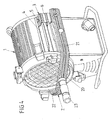
- Fig. 1 shows a perspective view of a headlight with a headlight housing 1, which is composed of a lamp housing 10 and a functional housing 13 with a front cover 11 and a rear cover 12.
- the front cover 11 is connected to a lens frame 14, which contains claws for receiving attachment elements such as diffusers, filter disks, protective disks, swing gate, color changer, shutter and the like, and is connected to the lamp housing 10 via a hinge and a tensioning device 15.
- a bracket 2 To connect the headlamp with a tripod to the stationary arrangement of the headlamp or a rig for suspension of the headlamp a bracket 2 is provided, the two of Fig. 4 two arms 21, 22, a connecting arms 20, 22 connecting arm 20 and a centrally on Connecting arm 20 arranged connecting pin 23 has.
- the ends of the hanger arms 21, 22 are connected to Bügelanlenk Institute 3 arranged diametrically opposite one another on the headlight housing 1 or lamp housing 10.
- the Bügelanschitch 3 consist of a connected to the headlight housing 1 housing rail 4 and connected to the ends of the hanger arms 21, 22 bracket bearing 6, which is positively connected to the housing rail 4 and in the longitudinal direction, that is in the direction of the optical axis of the headlamp on the Housing rail 4 adjustable and in selected positions form and / or non-positively connected to the housing rail 4 is connected.
- the housing rail 4 includes two extending longitudinally of the headlight housing 1 longitudinal grooves 41, 42, which are arranged spaced from each other in the circumferential direction of the headlight housing 1. Between the longitudinal grooves 41, 42 is a sword 40 perpendicular from the housing rail 4 and the headlight housing 1 or lamp housing 10 and has a longitudinal slot 43 which extends over a substantial part of the length of the headlight housing 1 and through the one with the bracket bearing 6 connected locking pin 5 for additional guidance and for positive and / or non-positive determination of the bracket bearing 6 engages.
- the connection between the housing rail 4 and the bow bearing 6 can be solved and the bow bearing 6 can be changed to change the position of the Bügelanlenkung 3 with respect to the longitudinal direction of the headlight housing 1.
- an adjustment of the bracket bearing 6 on the housing rail 4 is again a positive and / or non-positive locking of the bracket bearing 6 with the housing rail 4.
- various center of gravity displacements of the bow linkage 3 can be made to achieve an optimal weight distribution of the headlight with respect to a tripod or a suspension depending on the attached to the attachment part 14 attachment elements.
- the housing rail 4 can either be formed as a profiled part of the headlight housing 1 or the lamp housing 10 or connected as an additional part to the headlight housing 1. If the housing rail 4 is formed as an additional part, it is preferable to provide a screw or plug connection between the front cover 11 and the rear cover 12, which is covered by the lens frame 14 in the region of the front cover 11.
- the back cover 12 may have positive locking elements into which a front side of the housing rail 4 is inserted, while in the front cover 11 holes are provided which are aligned with threaded holes on the front end side of the housing rail 4, so that the housing rail 4 are screwed to the front cover 11 can.
- a double-sided screw the housing rail 4 with the front cover 11 and the back cover 12 by means of screws 16, 17 as shown in FIG. 5 is possible.
- the sword 40 can be inserted into a longitudinal groove of the headlight housing 1 and, for example, by two front side Screws are connected to the front cover 11 and thus fixed to the headlight housing 1.
- FIG. 2 shows an enlarged detail view of the bow linkage 3 according to FIG. 1 with the bow bearing 6 which can be adjusted in the longitudinal direction of the optical axis of the headlight in accordance with the double arrow A on the housing rail 4.
- the bow bearing 6 consists of a bow bearing plate 60, from which two bow bearing arms 64, 65 protrude in the direction of the housing rail 4 or the headlight housing 1 and at their ends with bow bearing webs 61, 62 into the longitudinal grooves 41, 42 engage the housing rail 4, wherein the bracket support webs 61, 62 are angled towards the bottom of the headlamp.
- a bore for receiving the locking pin 5 is arranged, which engages through the longitudinal slot 43 of the vertically projecting from the housing rail 4 sword 40.
- the tensioning device 8 has a tensioning lever 81, a clamping axis 80 engaging through the bow bearing 6 and a disk 83.
- Fig. 3 shows in a longitudinal section through the Bügelanlenkung 3, the connection between the bow bearing 6 and the housing rail 4 and the arrangement and design of the locking pin 5 and its connection to the sword 40 of the housing rail.
- the protruding from the bracket bearing plate 60 of the strap bearing 6 in the direction of the housing rail 4 upper and lower bracket bearing arms 64, 65 have in the longitudinal grooves 41, 42 of the housing rail engaging bracket support webs 61, 62, whose ends are crowned and in hollow cylindrical sections of the longitudinal grooves 41st , 42 intervene.
- This positive connection between the convex bracket bearing webs 61, 62 and the hollow cylindrical longitudinal grooves 41, 42 is a captive connection between the bow bearing 6 and the housing rail 4 and the corresponding part of the headlight housing 1 made.
- the bow bearing 6 is inserted from one of the end faces of the headlight housing in the housing rail 4 and connected by attaching the front cover 11 and the back cover 12 captive with the headlight housing 1.
- the locking pin 5 is inserted through a bore 66 in the upper bow bearing arm 64, engages through the longitudinal slot 43 of the sword 40 and through a bore 67 in the lower bow bearing arm 65.
- a cone 52 In its through the longitudinal slot 43 of the sword 40 cross-section center portion of the locking pin 5 is a cone 52, the shape of which coincides with a plurality of cone openings 44 distributed in the longitudinal direction of the longitudinal slot 43 of the sword 40.
- a compression spring 7 is arranged, which presses the cone 52 against the sword 40 or in one of the cone openings 44.
- the locking pin 5 is pressed against the bias of the compression spring 70 and thus the cone 52 is brought out of engagement with the respective cone opening 44 in the sword 40.
- the bracket bearing 6 By subsequent displacement of the bracket bearing 6 on the housing rail 4 is a shift of emphasis of the headlamp housing 1 shown in FIG. 1 until the cone 52 of the locking pin 5 engages in a cone opening 44 in the sword 40 under the action of spring preload.
- the locking pin 5 has a screw head 51 or is connected to a clamping lever 54 shown in dashed lines, which protrudes from the upper bracket bearing arm 64 for easy accessibility. At its projecting through the lower bracket support arm 65 end of the locking pin 5 is provided with a thread on which a clamping nut 53 is screwed. By screwing the locking pin 5 with the clamping nut 53 of the upper and lower bracket bearing arm 64, 65 are braced against each other and Thus, a frictional connection between the bracket bearing 6 and the Bügelanlenkung 3 and the housing rail 4 and the headlight housing 1 ago.
- the provided for tilt adjustment of the headlight housing 1 relative to the bracket 2 clamping device 8 is composed of a clamping lever 81 shown in FIG. 2 or in Fig. 3 81 ', a cross through the bow bearing 6 clamping axis 80 and a longitudinally slotted box section 63rd the clamping ring 6 used clamping element in the form of a clamping nut 82 together, which is screwed onto a threaded portion of the clamping axis 80.
- the clamping device 8 on a disc brake device in which, for example, the bow bearing 6 is connected to a brake disc, while the tensioning device 8 preferably on the periphery of the brake disc engaging brake pads, the brake disc frictional and because of the Lock the lever arm with high clamping force in any position.
- a quasi-continuous adjustment of the Bügelanlenkung 3 can be made by adjacent cone openings 44 in the longitudinal slot 43 of the sword 40 and thus allow arbitrary fine-stage longitudinal adjustment of the Bügelanlenkung 3 depending on the number and weight of the attachment elements.
- At least one transport position for the bracket 2 in which he claimed a minimum space.
- Such a transport position is shown in perspective in Fig. 4 and shows the displaced to the rear end of the headlight housing 1 Bügelanlenkung 3 with the displaced to the end of the housing rail 4 bracket bearing 6 and engaging in a positive recess of the sword 40 of the housing rail 4 locking pin. 5
- FIG. 5 shows in a perspective view of a headlight housing 1 with a bracket 2 one of the possible connection variants between the housing rail 4 and the headlight housing 1.
- the housing rail 4 is inserted into a positive rail receptacle in the front cover 11 of the headlight housing 1 and after placing the back cover 12 secured by screw 16, 17.
- the screw connections 16, 17 can simultaneously establish a connection between the rear cover 12 and the lamp housing 10.
- the sword 40 is inserted into a longitudinal groove of the lamp housing 10, for example, from the back of the headlight housing 1, and inserted into a positive reception of the front cover 11. After placing the back cover 12 on the lamp housing 10, a connection between the sword 40 and the back cover 12 or the headlight housing 1 is produced by means of the screw 16, 17.
- a screw connection can also be provided there analogous to the screw connections 16, 17 in the rear cover, which is covered by the lens frame 14.
Abstract
Description
Die Erfindung bezieht sich auf eine Vorrichtung zum Verbinden eines Scheinwerfers mit einem Bügel gemäß dem Oberbegriff des Anspruchs 1.The invention relates to a device for connecting a headlamp with a bracket according to the preamble of
Scheinwerfer für Bühnen-, Studio-, Film-, Fernseh- oder Eventeinsatz können sowohl stehend in Verbindung mit einem Stativ als auch hängend in Verbindung mit einer als Rig bezeichneten Studioaufhängung über eine Stangenbedienung mit oder ohne motorischer Fernbedienung eingesetzt werden. Die Verbindung des Scheinwerfers mit einem Stativ oder Rig erfolgt mit einem für die stehende oder hängende Anbringung des Scheinwerfers um das Scheinwerfergehäuse verschwenkbaren Bügel, dessen Bügelarme über diametral zueinander angeordnete Bügelanlenkungen mit dem Scheinwerfergehäuse verbundenen sind. Der um eine Querachse des Scheinwerfergehäuses schwenkbare Bügel kann mittels einer Spannvorrichtung in einer beliebigen Winkelstellung gegenüber der Horizontalen fixiert werden, so dass die Neigung des Scheinwerfers in Bezug auf ein Stativ oder ein Rig veränderbar ist.Stage, studio, film, television or event lighting fixtures can be used standing in conjunction with a tripod or suspended in conjunction with a studio suspension called a rig via a bar control with or without a motorized remote control. The connection of the headlight with a tripod or rig takes place with a for the standing or hanging mounting of the headlight about the headlight housing pivotable bracket whose arms are connected via diametrically arranged Bügelanlenkungen with the headlight housing. The pivotable about a transverse axis of the headlight housing bracket can be fixed by means of a clamping device in any angular position relative to the horizontal, so that the inclination of the headlight with respect to a tripod or a rig is variable.
Die Bügelanlenkungen bestehen in einer ersten Ausführungsform aus diametral am Scheinwerfergehäuse angeordneten Bügelaufnahmen und mit den Bügelaufnahmen des Scheinwerfergehäuses verbindbaren Anlenkungen an den Enden der Bügelarme. Bei dieser Art der Bügelanlenkung ist nur eine Neigungsverstellung des Scheinwerfers, aber keine Schwerpunktverlagerung des Scheinwerfers in Bezug auf den Scheinwerferbügel möglich, um unterschiedliche Gewichte infolge der Anzahl und Art von Vorsatzteilen und Zusatzeinrichtungen am Frontteil des Scheinwerfers auszugleichen.The Bügelanlenkungen consist in a first embodiment of diametrically arranged on the spotlight housing shots and connectable to the bracket shots of the headlight housing hinges at the ends of the hanger arms. In this type of Bügelanlenkung only a tilt adjustment of the headlamp, but no shift of focus of the headlamp in relation to the headband bracket is possible to compensate for different weights due to the number and type of attachment parts and accessories on the front part of the headlamp.
In einer zweiten Ausführungsform wird eine Friktionsverbindung zwischen den Bügelarmen und dem Scheinwerfergehäuse durch gegeneinander verspannte Klauen an den Enden der Bügelarme, die in Formschlusselementen am Scheinwerfergehäuse oder mit dem Scheinwerfergehäuse verbundenen und in Längsrichtung des Scheinwerfergehäuses ausgerichteten Stangen abgestützt sind.In a second embodiment, a frictional connection between the bail arms and the headlight housing by claws clamped against each other at the ends of the bail arms, which are supported in positive locking elements on the headlight housing or with the headlight housing and aligned in the longitudinal direction of the headlight housing rods.
In der letztgenannten Ausführungsform ist zwar eine Längsverstellung der Bügelanlenkung möglich, auf Grund der Friktion zwischen Scheinwerferbügel und Scheinwerfergehäuse ist eine Verstellung der Bügelanlenkung jedoch nur sehr eingeschränkt möglich und daher aus Sicherheitsgründen auch nur begrenzt einsetzbar. Zudem führt die Friktion zwischen Scheinwerferbügel und Scheinwerfergehäuse zu einer erheblichen Verspannung und damit zu der Gefahr einer Beschädigung des Scheinwerfergehäuses.Although in the latter embodiment, a longitudinal adjustment of the Bügelanlenkung is possible, due to the friction between the headlight bracket and the headlight housing but an adjustment of the ironing linkage is only very limited and therefore for security reasons only limited use. In addition, the friction between the headlight bracket and headlight housing leads to considerable tension and thus to the risk of damaging the headlight housing.
Aufgabe der vorliegenden Erfindung ist es, eine einfach aufgebaute und einfach handhabbare, sichere Bügelanlenkung zu schaffen, die eine Schwerpunktverlagerung und eine Patz sparende Transportstellung des Bügels ohne zusätzliche mechanische Beanspruchung des Scheinwerfergehäuses ermöglicht.Object of the present invention is to provide a simple design and easy to handle, secure Bügelanlenkung that allows a center of gravity displacement and a Patz-saving transport position of the bracket without additional mechanical stress on the headlight housing.
Diese Aufgabe wird erfindungsgemäß durch die Merkmale des Anspruchs 1 gelöst.This object is achieved by the features of
Die erfindungsgemäße Lösung stellt eine einfach aufgebaute und einfach handhabbare, sichere Bügelanlenkung mit der Möglichkeit einer Schwerpunktverlagerung und einer Patz sparenden Transportstellung des Bügels ohne zusätzliche mechanische Beanspruchung des Scheinwerfergehäuses bereit.The solution according to the invention provides a simply constructed and easy to handle, secure ironing linkage with the possibility of shifting the center of gravity and a Patz-saving transport position of the bracket without additional mechanical stress on the headlight housing.
Die erfindungsgemäße Lösung geht von der Überlegung aus, durch eine in Richtung der optischen Achse des Scheinwerfers veränderliche, form- und/oder kraftschlüssige Bügelanlenkung eine einfache Schwerpunktverlagerung durchführen zu können, ohne dass dies zu erhöhten Materialspannungen wie bei einer Verspannung der Bügelarme mit dem Scheinwerfergehäuse führt.The solution according to the invention is based on the idea of being able to carry out a simple shift of center of gravity by a variable in the direction of the optical axis of the headlamp, positive and non-rigid Bügelanlenkung, without this leading to increased material stresses as in a bracing of the hanger arms with the headlamp housing ,
Vorzugsweise besteht die veränderliche Bügelanlenkung aus mindestens einer sich in Richtung der optischen Achse des Scheinwerfers erstreckenden Gehäuseschiene und einem mit der Gehäuseschiene formschlüssig verbundenen und entlang dieser verstellbaren Bügellager, dessen Stellung in Bezug auf die Gehäuseschiene form- und/oder kraftschlüssig feststellbar ist, so dass die Verstellung der Bügelanlenkung in einfacher Handhabung durch ein Verschieben des Bügellagers auf der sich in Richtung der optischen Achse des Scheinwerfers erstreckenden Gehäuseschiene vorgenommen und die Fixierung der Bügelanlenkung durch ein form- und/oder kraftschlüssiges Feststellen des Bügellagers in der gewählten Stellung an der Gehäuseschiene erfolgen kann.Preferably, the variable Bügelanlenkung consists of at least one extending in the direction of the optical axis of the headlight housing rail and a form-fitting connected to the housing rail and along this adjustable bracket bearings, the position with respect to the housing rail is positively and / or non-positively detected, so that the Adjustment of the bow linkage easier Handling by moving the bracket bearing made on the extending in the direction of the optical axis of the headlight housing rail and the fixation of the Bügelanlenkung can be done by a positive and / or non-positive locking of the bracket bearing in the selected position on the housing rail.
Durch die Anordnung von zwei diametral zueinander am Scheinwerfergehäuse angeordneten und sich in Richtung der optischen Achse des Scheinwerfers erstreckenden Gehäuseschienen ist ein einfaches, verkantfreies Verschieben des Bügellagers auf der sich in Richtung der optischen Achse des Scheinwerfers erstreckenden Gehäuseschiene und eine symmetrische Befestigung der eingestellten Bügelanlenkung gewährleistet.Due to the arrangement of two diametrically arranged on the headlight housing and extending in the direction of the optical axis of the headlight housing rails a simple, tilting displacement of the bracket bearing is ensured on extending in the direction of the optical axis of the headlight housing rail and a symmetrical attachment of the set Bügelanlenkung.
Die Feststellung des Bügellagers an der Gehäuseschiene kann stufenlos mit einer kraftschlüssigen Befestigung des Bügellagers an der Gehäuseschiene oder formschlüssig bzw. kraft- und formschlüssig in vorgegebenen Stellungen an der Gehäuseschiene erfolgen.The determination of the strap bearing on the housing rail can be made continuously with a non-positive attachment of the strap bearing on the housing rail or positive or force and form-fitting in predetermined positions on the housing rail.
Durch eine in Stufen veränderbare, zumindest formschlüssige Bügelanlenkung können mehrere diskrete Stellungen vorgesehen werden, beispielsweise mindestens zwei Betriebsstellungen zur Schwerpunktverlagerung des Scheinwerfers sowie eine Transportstellung der Bügelanlenkung, in der der Befestigungsbügel in eine Stellung mit minimalem Platzbedarf verstellbar ist.By a variable in steps, at least positive Bügelanlenkung multiple discrete positions can be provided, for example, at least two operating positions for shifting the center of gravity of the headlamp and a transport position of the Bügelanlenkung in which the mounting bracket is adjustable to a position with minimal space requirements.
Alternativ kann eine stufenlose oder feinstufig einstellbare Bügelanlenkung vorgesehen werden, die eine Vielzahl von Betriebsstellungen und alternativen Transportstellungen umfasst, so dass Schwerpunktverlagerungen unter Berücksichtigung der Anzahl und des Gewichts von Vorsatzelementen des Scheinwerfers optimiert werden können.Alternatively, a stepless or finely adjustable bar linkage can be provided, which includes a plurality of operating positions and alternative transport positions, so that center of gravity displacements can be optimized taking into account the number and weight of headlight attachment elements.
Eine vorteilhafte Ausgestaltung der erfindungsgemäßen Lösung ist dadurch gekennzeichnet, dass die Gehäuseschienen zueinander beabstandete, parallel zur optischen Achse des Scheinwerfers verlaufende Längsnuten, in die von einer parallel zum Scheinwerfergehäuse ausgerichteten Bügellagerplatte abstehende Bügellagerstege eingreifen, sowie ein im Wesentlichen senkrecht vom Scheinwerfergehäuse abstehendes Schwert aufweisen, das mit einem Verriegelungselement des Bügellagers zur Festlegung der Stellung des Scheinwerfers in Bezug auf den Scheinwerferbügel kraft- und/oder formschlüssig zusammenwirkt.An advantageous embodiment of the solution according to the invention is characterized in that the housing rails spaced from each other, parallel to the optical axis of the headlamp longitudinal grooves, engage in the projecting from a parallel to the spotlight housing bracket mounting plate bracket webs, and have a substantially perpendicular protruding from the headlight housing sword, the with a locking element of the bracket bearing to determine the position of the headlamp in relation to the headlight bracket force and / or positively cooperates.
Durch die Anordnung von zueinander beabstandeten und parallel zur optischen Achse des Scheinwerfers verlaufenden Längsnuten an den Gehäuseschienen mit darin eingreifenden Bügellagerstegen ist eine sichere Verstellung des Bügellagers auf der Gehäuseschiene ohne die Gefahr eines Verkantens gewährleistet, während durch die kraft- und/oder formschlüssige Verbindung zwischen dem Verriegelungselement des Bügellagers und dem im Wesentlichen senkrecht vom Scheinwerfergehäuse abstehenden Schwert zumindest der Festlegung des Bügellagers an der Gehäuseschiene dient und eine einfache und sicher handhabbare Verriegelung der jeweiligen Längseinstellung der Bügelanlenkung sicherstellt.By arranging spaced apart and parallel to the optical axis of the headlamp longitudinal grooves on the housing rails with engaging strap support webs secure adjustment of the strap bearing on the housing rail is guaranteed without the risk of tilting, while the non-positive and / or positive connection between the Locking element of the bracket bearing and the sword protruding substantially perpendicularly from the headlight housing at least the attachment of the bracket bearing on the housing rail and ensures a simple and secure handle locking the respective longitudinal adjustment of the Bügelanlenkung.
Zusätzlich kann eine kraftschlüssige Arretierung des Bügellagers mit dem Scheinwerfergehäuse durch eine gegenseitige Verspannung der Bügellagerstege vorgesehen werden, durch die ohne wesentliche Mehrbelastung des Scheinwerfergehäuses oder des Bügellagers eine Entlastung der formschlüssigen Verbindung zwischen dem Verriegelungsstift und dem Schwert geschaffen wird. Darüber hinaus ermöglicht diese Ausgestaltung der erfindungsgemäßen Lösung auch die Einnahme von Zwischenpositionen zwischen den am Schwert vorgesehenen Verbindungsstufen, wenn der Scheinwerfer insbesondere nicht oder nur geringfügig geneigt betrieben wird. Insbesondere bei einer feinstufigen Schwerpunktverstellung ist auch in diesen Zwischenstellungen ein Höchstmaß an Sicherheit gegeben, da bei einem Lösen der kraftschlüssigen Verbindung die Bügelanlenkung in die nächste Formschlussstufe einrastet und damit eine weitere, unbeabsichtigte Längsverstellung verhindert.In addition, a non-positive locking of the bracket bearing to the headlight housing can be provided by a mutual tensioning of the bracket support webs by the load without significant additional burden of the headlight housing or the bracket bearing a relief of the positive connection between the locking pin and the sword is created. In addition, this embodiment of the solution according to the invention also enables the taking of intermediate positions between the connection stages provided on the sword, when the headlamp is operated in particular not or only slightly inclined. Particularly in the case of a finely graduated center of gravity adjustment, maximum safety is also provided in these intermediate positions, since when the non-positive connection is released, the stirrup link engages in the next positive engagement step and thus prevents further, unintentional longitudinal adjustment.
Vorzugsweise sind die Bügellagerstege und die Längsnuten formschlüssig miteinander verbunden, beispielsweise in der Weise, dass die Enden der Bügellagerstege ballig ausgebildet sind und die Längsnuten einen hohlzylindrischen Teil aufweisen, in den die balligen Enden der Bügellagerstege von einer der Stirnseiten des Scheinwerfergehäuses aus einsetzbar sind.Preferably, the bow bearing webs and the longitudinal grooves are positively connected to each other, for example in such a way that the ends of the bow bearing webs are formed crowned and the longitudinal grooves have a hollow cylindrical portion into which the crowned ends of the bow bearing webs of one of the end faces of the headlight housing can be used.
Durch die Ausbildung eines Längsschlitzes im Schwert mit darin eingreifendem, in Verriegelungsstellung vorgespannten Verriegelungsstift wird eine optisch leicht wahrnehmbare Einstellung unterschiedlicher Betriebsstellungen und einer oder mehrere Transportstellungen ermöglicht und gleichzeitig durch die Vorspannung des Verriegelungsstiftes in Verriegelungsstellung eine sichere Einstellung und Verbindung zwischen Scheinwerferbügel und Scheinwerfergehäuse gewährleistet.Due to the formation of a longitudinal slot in the sword with intervening, biased in locking position locking pin a visually easily perceptible setting different operating positions and one or more transport positions allows and at the same time ensures a secure adjustment and connection between the headlight bracket and headlight housing by the bias of the locking pin in the locked position.
Vorzugsweise erfolgt die formschlüssige, in Stufen veränderbare Bügelanlenkung mittels im Längsschlitz des Schwertes angeordneter diskreter Anlenkpunkte, in die der in Verriegelungsstellung vorgespannte Verriegelungsstift einrastet.Preferably, the positive, variable in steps Bügelanlenkung carried out by means disposed in the longitudinal slot of the sword discrete articulation points, in which engages the biased in the locking position locking pin.
Da das Schwert senkrecht vom Scheinwerfergehäuse absteht, ist eine einfache Handhabung beim Einstellen der Bügelanlenkung gewährleistet, indem zum Verstellen der Bügelanlenkung der Verriegelungsstift gegen die Vorspannung aus seinem formschlüssigen Eingriff in das Schwert gelöst und nach dem Verstellen der Bügelanlenkung der Verriegelungsstift unter Einwirkung der Vorspannung wieder formschlüssig in das Schwert einrastet.Since the sword protrudes perpendicularly from the headlight housing, a simple handling when adjusting the Bügelanlenkung is ensured by released to adjust the Bügelanlenkung the locking pin against the bias from its positive engagement with the sword and after adjusting the Bügelanlenkung the locking pin under the action of the bias again form-fitting snapped into the sword.
Vorzugsweise weist der Längsschlitz des Schwertes mehrere konische Ausnehmungen auf, in die ein Konus des federbelasteten Verriegelungsstiftes zur kraft- und/oder formschlüssigen Festlegung der Stellung des Scheinwerfers in Bezug auf den Scheinwerferbügel eingreiftPreferably, the longitudinal slot of the sword has a plurality of conical recesses into which engages a cone of the spring-loaded locking pin for non-positive and / or positive fixing of the position of the headlamp with respect to the headlight bracket
Durch die konischen Ausnehmungen im Längsschlitz des Schwertes zur Vorgabe mehrerer Betriebs- und Transportstellungen in Verbindung mit dem Konus des federbelasteten Verriegelungsstiftes ist eine Selbstzentrierung der verschieden diskreten Bügelanlenkpositionen gewährleistet und gleichzeitig sicher gestellt, dass die jeweilige Längseinstellung der Bügelanlenkung ohne zusätzliche Materialbeanspruchungen sicher eingehalten wird.Due to the conical recesses in the longitudinal slot of the sword to specify multiple operating and transport positions in conjunction with the cone of the spring-loaded locking pin self-centering of different discrete Bügelanlenkpositionen is ensured while ensuring that the respective longitudinal adjustment of the Bügelanlenkung is safely maintained without additional material stresses.
Die aus Gehäuseschienen und formschlüssig mit den Gehäuseschienen verbundenen Bügellagern gebildete veränderliche Bügelanlenkung ermöglicht es, die Gehäuseschienen einstückig als vorzugsweise integralen Teil des Scheinwerfergehäuses auszubilden oder eine Verbindung zwischen Gehäuseschiene und Scheinwerfergehäuse vorzusehen, so dass auch eine nachträgliche Ausrüstung eines Scheinwerfers mit einer veränderlichen Bügelanlenkung möglich ist.The variable Bügelanlenkung formed of housing rails and form-fitting connected to the housing rails bracket bearings makes it possible to integrally form the housing rails as a preferably integral part of the headlight housing or provide a connection between the housing rail and headlight housing, so that a subsequent equipment of a headlamp with a variable Bügelanlenkung is possible.
Eine Steck- und/oder Schraubverbindung zwischen der Gehäuseschiene und dem Scheinwerfergehäuse wird vorzugsweise im Bereich der Stirnseiten des Scheinwerfergehäuses angeordnet und durch Blenden oder einen Front- und Rückseitenteil des Scheinwerfergehäuses abgedeckt.A plug and / or screw connection between the housing rail and the headlight housing is preferably arranged in the region of the end faces of the headlight housing and covered by panels or a front and rear side part of the headlight housing.
Dementsprechend kann die Gehäuseschiene in eine formschlüssige Aufnahme am Scheinwerfergehäuse oder am Front- oder Rückseitenteil eingesteckt und am jeweils entgegen gesetzten Ende mit dem Front- oder Rückseitenteil durch stirnseitig eingeführte Schrauben fixiert werden. Alternativ ist auch eine beidseitige Schraubverbindung mit dem Front- und Rückseitenteil des Scheinwerfergehäuses oder eine beidseitige Steckverbindung mit dem Front- und Rückseitenteil des Scheinwerfergehäuses verwendbar, wenn das Front- und Rückseitenteil an ein Lampengehäuse angeschraubt werden.Accordingly, the housing rail can be inserted into a positive receptacle on the headlight housing or on the front or rear side part and on each opposite end to be fixed with the front or rear side by frontally introduced screws. Alternatively, a double-sided screw with the front and back of the headlight housing or a two-sided connector with the front and rear side of the headlight housing is used when the front and rear side are screwed to a lamp housing.
Zur Neigungsverstellung des Scheinwerfers ist mindestens einer der Bügelarme über eine Spannvorrichtung mit dem Bügellager verbunden. Die Spannvorrichtung kann aus einem Spannhebel, einer durch das Bügellager greifenden Spannachse und einem mit dem Bügellager verbundenen Spannelement, insbesondere in Form einer in ein geschlitztes Kastenprofil des Bügellagers eingesetzten Mutter, oder aus einer Scheibenbremseinrichtung mit einer mit dem Bügellager verbundenen Scheibe und einem mit einem Spannhebel verbundenen Bremselement bestehen.For tilt adjustment of the headlight at least one of the bracket arms is connected via a tensioning device with the bracket bearing. The tensioning device may comprise a tensioning lever, a tensioning axis passing through the strap bearing and a tensioning element connected to the strap bearing, in particular in the form of a nut inserted into a slotted box profile of the strap bearing, or a disc brake device having a disc connected to the strap bearing and one with a tensioning lever connected brake element exist.
Eine vorteilhafte Ausgestaltung der Erfindung ist durch eine Transportstellung der Bügelanlenkung, in der der Bügel in eine Stellung mit minimalem Platzbedarf verstellbar ist, und mindestens zwei Betriebsstellungen zur Schwerpunktverlagerung des Scheinwerfers gekennzeichnet.An advantageous embodiment of the invention is characterized by a transport position of the Bügelanlenkung in which the bracket is adjustable to a position with minimal space requirements, and at least two operating positions for shifting the center of gravity of the headlamp.
Durch die Vorgabe bestimmter Längsverstellungen der Bügelanlenkung ist eine einfache Handhabung und sichere Verbindung zwischen dem Scheinwerferbügel und dem Scheinwerfer gewährleistet, wobei sich die Transportstellung der Bügelanlenkung vorzugsweise am vorderen oder hinteren Ende des Verstellbereichs der Bügelanlenkung befindet, in der die Befestigungsarme des Bügels parallel zur optischen Achse des Scheinwerfers ausgerichtet sind und die Betriebsstellungen zumindest eine in Bezug auf die Abstrahlrichtung des Scheinwerfers vordere Stellung für eine Verbindung der Lichtaustrittsöffnung des Scheinwerfers und/oder schweren optischen Abdeckelementen oder Zusatzeinrichtungen wie Shutter, Farbwechsler, Flügeltore oder dergleichen und eine hintere Stellung enthalten, in der die Lichtaustrittsöffnung des Scheinwerfers keine Abdeckelemente oder Abdeckelemente bzw. Zusatzeinrichtungen mit geringem Gewicht aufweist.By specifying certain longitudinal adjustments of the ironing an easy handling and secure connection between the headlight bracket and the headlamp is ensured, with the transport position of Bügelanlenkung preferably located at the front or rear end of the adjustment of the Bügelanlenkung in which the mounting arms of the bracket parallel to the optical axis the headlamps are aligned and the operating positions at least one with respect to the emission direction of the headlamp front position for connection of the light exit opening of the headlamp and / or heavy optical cover elements or accessories such as shutter, color changer, swing gates or the like and a rear position, in which the Light emission opening of the headlamp has no cover elements or cover elements or additional devices with low weight.
Anhand eines in der Zeichnung dargestellten Ausführungsbeispieles soll der der Erfindung zugrunde liegende Gedanke näher erläutert werden. Es zeigen:
- Fig. 1
- eine perspektivische Darstellung eines Scheinwerfers mit einer längsverstellbaren Bügelanlenkung;
- Fig. 2
- eine vergrößerte perspektivische Ansicht der Bügelanlenkung gemäß Fig. 1;
- Fig. 3
- einen Schnitt durch die Bügelanlenkung gemäß Fig. 2;
- Fig. 4
- eine perspektivische Darstellung eines Scheinwerfers mit einem Bügel in Transportstellung und
- Fig. 5
- eine Rückseitenansicht des Scheinwerfers mit längsverstellbarer Bügelanlenkung und Befestigungspunkten für Gehäuseschienen.
- Fig. 1
- a perspective view of a headlamp with a longitudinally adjustable Bügelanlenkung;
- Fig. 2
- an enlarged perspective view of the Bügelanlenkung of FIG. 1;
- Fig. 3
- a section through the Bügelanlenkung of FIG. 2;
- Fig. 4
- a perspective view of a headlamp with a bracket in transport position and
- Fig. 5
- a rear view of the headlamp with longitudinally adjustable Bügelanlenkung and attachment points for housing rails.
Fig. 1 zeigt in perspektivischer Ansicht einen Scheinwerfer mit einem Scheinwerfergehäuse 1, das aus einem Lampengehäuse 10 und einem Funktionsgehäuse 13 mit einer Frontabdeckung 11 und einer Rückseitenabdeckung 12 zusammengesetzt ist. Die Frontabdeckung 11 ist mit einer Linsenfassung 14 verbunden, die Klauen zur Aufnahme von Vorsatzelementen wie Diffuser, Filterscheiben, Schutzscheiben, Flügeltor, Farbwechsler, Shutter und dergleichen enthält und über ein Scharnier und eine Spannvorrichtung 15 mit dem Lampengehäuse 10 verbunden ist.Fig. 1 shows a perspective view of a headlight with a
Zur Verbindung des Scheinwerfers mit einem Stativ zur stehenden Anordnung des Scheinwerfers oder einem Rig für eine Aufhängung des Scheinwerfers ist ein Bügel 2 vorgesehen, der gemäß Fig. 4 zwei Bügelarme 21, 22, einen die Bügelarme 21, 22 verbindenden Verbindungsarm 20 und einen mittig am Verbindungsarm 20 angeordneten Verbindungsbolzen 23 aufweist. Die Enden der Bügelarme 21, 22 sind mit diametral zueinander am Scheinwerfergehäuse 1 bzw. Lampengehäuse 10 angeordneten Bügelanlenkungen 3 verbunden.To connect the headlamp with a tripod to the stationary arrangement of the headlamp or a rig for suspension of the headlamp a
Die Bügelanlenkungen 3 bestehen aus einer mit dem Scheinwerfergehäuse 1 verbundenen Gehäuseschiene 4 und einem mit den Enden der Bügelarme 21, 22 verbundenen Bügellager 6, das formschlüssig mit der Gehäuseschiene 4 verbunden und in Längsrichtung, das heißt in Richtung der optischen Achse des Scheinwerfers, auf der Gehäuseschiene 4 verstellbar und in gewählten Stellungen form- und/oder kraftschlüssig mit der Gehäuseschiene 4 verbindbar ist.The Bügelanlenkungen 3 consist of a connected to the
Die Gehäuseschiene 4 enthält zwei in Längsrichtung des Scheinwerfergehäuses 1 verlaufende Längsnuten 41, 42, die in Umfangsrichtung des Scheinwerfergehäuses 1 zueinander beabstandet angeordnet sind. Zwischen den Längsnuten 41, 42 steht ein Schwert 40 senkrecht von der Gehäuseschiene 4 bzw. dem Scheinwerfergehäuse 1 oder Lampengehäuse 10 ab und weist einen Längsschlitz 43 auf, der sich über einen wesentlichen Teil der Länge des Scheinwerfergehäuses 1 erstreckt und durch den ein mit dem Bügellager 6 verbundener Verriegelungsstift 5 zur zusätzlichen Führung und zur form- und/oder kraftschlüssigen Feststellung des Bügellagers 6 greift.The
Durch Betätigen des Verriegelungsstiftes 5 kann die Verbindung zwischen der Gehäuseschiene 4 und dem Bügellager 6 gelöst und das Bügellager 6 zur Veränderung der Stellung der Bügelanlenkung 3 in Bezug auf die Längsrichtung des Scheinwerfergehäuses 1 verändert werden. Nach einer Verstellung des Bügellagers 6 auf der Gehäuseschiene 4 erfolgt wiederum eine form- und/oder kraftschlüssige Verriegelung des Bügellagers 6 mit der Gehäuseschiene 4. Durch eine stufenlose Verstellung des Bügellagers 6 auf der Gehäuseschiene 4 oder durch die Vorgabe mehrerer diskreter Stellungen auf der Gehäuseschiene 4 können verschiedene Schwerpunktverlagerungen der Bügelanlenkung 3 vorgenommen werden, um in Abhängigkeit von den mit dem Vorsatzteil 14 verbundenen Vorsatzelementen eine optimale Gewichtsverteilung des Scheinwerfers in Bezug auf ein Stativ oder eine Aufhängung zu erzielen.By pressing the
Die Gehäuseschiene 4 kann entweder als profiliertes Teil des Scheinwerfergehäuses 1 bzw. des Lampengehäuses 10 ausgebildet oder als Zusatzteil mit dem Scheinwerfergehäuse 1 verbunden werden. Ist die Gehäuseschiene 4 als Zusatzteil ausgebildet, so wird vorzugsweise eine Schraub- oder Steckverbindung zwischen der Frontabdeckung 11 und der Rückseitenabdeckung 12 vorgesehen, die im Bereich der Frontabdeckung 11 durch die Linsenfassung 14 abgedeckt ist. Beispielsweise kann die Rückseitenabdeckung 12 Formschlusselemente aufweisen, in die eine Stirnseite der Gehäuseschiene 4 einsetzbar ist, während in der Frontabdeckung 11 Bohrungen vorgesehen sind, die mit Gewindebohrungen an der frontseitigen Stirnseite der Gehäuseschiene 4 fluchten, so dass die Gehäuseschiene 4 mit der Frontabdeckung 11 verschraubt werden kann. Alternativ ist auch eine beidseitige Schraubverbindung der Gehäuseschiene 4 mit der Frontabdeckung 11 und der Rückseitenabdeckung 12 mittels Schrauben 16, 17 gemäß Fig. 5 möglich.The
In einer weiteren alternativen Ausführungsform kann das Schwert 40 in eine Längsnut des Scheinwerfergehäuses 1 eingeschoben und beispielsweise durch zwei frontseitige Schrauben mit der Frontabdeckung 11 verbunden und somit am Scheinwerfergehäuse 1 festgelegt werden.In a further alternative embodiment, the
Fig. 2 zeigt in vergrößerter Detailansicht die Bügelanlenkung 3 gemäß Fig. 1 mit dem in Längsrichtung der optischen Achse des Scheinwerfers entsprechend dem Doppelpfeil A auf der Gehäuseschiene 4 verstellbaren Bügellager 6.2 shows an enlarged detail view of the
Das Bügellager 6 besteht entsprechend der Schnittdarstellung gemäß Fig. 3 aus einer Bügellagerplatte 60, von der zwei Bügellagerarme 64, 65 in Richtung auf die Gehäuseschiene 4 bzw. das Scheinwerfergehäuse 1 abstehen und an ihren Enden mit Bügellagerstegen 61, 62 in die Längsnuten 41, 42 der Gehäuseschiene 4 eingreifen, wobei die Bügellagerstege 61, 62 zur Unterseite des Scheinwerfers hin abgewinkelt sind. In einer Vertiefung des oberen Bügellagerarms 64 ist eine Bohrung zur Aufnahme des Verriegelungsstiftes 5 angeordnet, der durch den Längsschlitz 43 des senkrecht von der Gehäuseschiene 4 abstehenden Schwertes 40 greift.According to the sectional representation according to FIG. 3, the bow bearing 6 consists of a
Die Verbindung des Bügellagers 6 mit dem Bügelarm 21 des Bügels 2 erfolgt über eine Spannvorrichtung 8, mit der die Neigung des Scheinwerfergehäuses 1 gegenüber dem Bügel 2 und damit gegenüber einem Stativ oder einer Aufhängung einstell- und arretierbar ist. Die Spannvorrichtung 8 weist einen Spannhebel 81, eine durch das Bügellager 6 greifende Spannachse 80 und eine Scheibe 83 auf.The connection of the bracket bearing 6 with the
Nähere Einzelheiten der formschlüssigen Verbindung zwischen dem Bügellager 6 und dem Schwert 40 der Gehäuseschiene 4 sowie der Spannvorrichtung 8 sind der Schnittdarstellung gemäß Fig. 3 zu entnehmen, die nachstehend näher beschrieben wird.Further details of the positive connection between the
Fig. 3 zeigt in einem Längsschnitt durch die Bügelanlenkung 3 die Verbindung zwischen dem Bügellager 6 und der Gehäuseschiene 4 sowie die Anordnung und Ausgestaltung des Verriegelungsstiftes 5 und dessen Verbindung mit dem Schwert 40 der Gehäuseschiene 4.
Die von der Bügellagerplatte 60 des Bügellagers 6 in Richtung auf die Gehäuseschiene 4 abstehenden oberen und unteren Bügellagerarme 64, 65 weisen in die Längsnuten 41, 42 der Gehäuseschiene eingreifende Bügellagerstege 61, 62 auf, deren Enden ballig ausgebildet sind und in hohlzylindrische Abschnitte der Längsnuten 41, 42 eingreifen. Durch diese formschlüssige Verbindung zwischen den balligen Bügellagerstegen 61, 62 und den hohlzylindrischen Längsnuten 41, 42 wird eine unverlierbare Verbindung zwischen dem Bügellager 6 und der Gehäuseschiene 4 bzw. dem entsprechenden Teil des Scheinwerfergehäuses 1 hergestellt. Zum Verbinden des Bügellagers 6 mit der Gehäuseschiene 4 wird das Bügellager 6 von einer der Stirnseiten des Scheinwerfergehäuses in die Gehäuseschiene 4 eingesetzt und durch Anbringen der Frontabdeckung 11 bzw. der Rückseitenabdeckung 12 unverlierbar mit dem Scheinwerfergehäuse 1 verbunden.Fig. 3 shows in a longitudinal section through the
The protruding from the
Der Verriegelungsstift 5 ist durch eine Bohrung 66 im oberen Bügellagerarm 64 gesteckt, greift durch den Längsschlitz 43 des Schwertes 40 und durch eine Bohrung 67 im unteren Bügellagerarm 65. In seinem durch den Längsschlitz 43 des Schwertes 40 greifenden Mittenabschnitt ist der Verriegelungsstift 5 mit einem Konus 52 versehen, dessen Form mit mehreren in Längsrichtung des Längsschlitzes 43 des Schwertes 40 verteilt angeordneten Konusöffnungen 44 übereinstimmt. Zwischen dem Konus 52 und dem unteren Bügellagerarm 65 ist eine Druckfeder 7 angeordnet, die den Konus 52 gegen das Schwert 40 bzw. in eine der Konusöffnungen 44 drückt. Dadurch wird eine formschlüssige Verbindung zwischen dem Bügellager 6 und der Gehäuseschiene 4 bzw. dem Scheinwerfergehäuse 1 in vorgegebenen Positionen entlang des Schwertes 40 hergestellt.The
Zum Verstellen der Bügelanlenkung 3 wird der Verriegelungsstift 5 gegen die Vorspannung der Druckfeder 70 gedrückt und damit der Konus 52 außer Eingriff mit der jeweiligen Konusöffnung 44 im Schwert 40 gebracht. Durch anschließendes Verschieben des Bügellagers 6 auf der Gehäuseschiene 4 erfolgt eine Schwerpunktverlagerung des Scheinwerfergehäuses 1 gemäß Fig. 1 bis der Konus 52 des Verriegelungsstiftes 5 in eine Konusöffnung 44 im Schwert 40 unter Einwirkung der Federvorspannung einrastet.To adjust the
In der in Fig. 3 dargestellten Ausführungsform ist zusätzlich eine stufenlos kraftschlüssige Verbindung zwischen der Bügelanlenkung 3 und der Gehäuseschiene 4 vorgesehen, deren Aufbau und Funktion nachstehend näher erläutert wird.In the embodiment shown in Fig. 3, a continuously non-positive connection between the
Der Verriegelungsstift 5 weist einen Schraubenkopf 51 auf oder ist mit einem gestrichelt dargestellten Spannhebel 54 verbunden, der zur leichten Zugänglichkeit vom oberen Bügellagerarm 64 absteht. An seinem durch den unteren Bügellagerarm 65 ragenden Ende ist der Verriegelungsstift 5 mit einem Gewinde versehen, auf das eine Spannmutter 53 aufgeschraubt ist. Durch Verschrauben des Verriegelungsstiftes 5 mit der Spannmutter 53 werden der obere und untere Bügellagerarm 64, 65 gegeneinander verspannt und stellen somit eine kraftschlüssige Verbindung zwischen dem Bügellager 6 bzw. der Bügelanlenkung 3 und der Gehäuseschiene 4 bzw. dem Scheinwerfergehäuse 1 her.The
Durch die Kombination einer formschlüssigen Verbindung zwischen dem Bügellager 6 und der Gehäuseschiene 4 in den durch die Konusöffnungen 44 im Schwert 40 vorgegebenen Positionen sowie durch eine kraftschlüssige Verbindung zwischen dem Bügellager 6 und der Gehäuseschiene 4 in stufenlos einstellbaren Positionen zwischen den durch die Konusöffnungen 43 vorgegebenen Stellungen der Bügelanlenkung 3 können sowohl beliebige Positionen der Bügelanlenkung 3 eingestellt werden als auch bestimmte, durch die Konusöffnungen 43 vorgegebene Positionen angefahren und als Standardeinstellungen verwendet werden.By the combination of a positive connection between the
Die zur Neigungseinstellung des Scheinwerfergehäuses 1 gegenüber dem Bügel 2 vorgesehene Spannvorrichtung 8 setzt sich aus einem in Fig. 2 dargestellten Spannhebel 81 oder in Fig. 3 dargestellten Spannknauf 81', einer durch das Bügellager 6 greifenden Spannachse 80 und einem in ein längs geschlitztes Kastenprofil 63 des Bügellagers 6 eingesetzten Spannelement in Form einer Spannmutter 82 zusammen, die auf einen Gewindeabschnitt der Spannachse 80 aufgeschraubt ist. Durch Verdrehen des Spannhebels 81 bzw. des Spannknaufs 81' im Uhrzeigersinn wird eine kraft- bzw. reibschlüssige Verbindung zwischen dem Bügelarm 21 und dem Bügellager 6 hergestellt, während ein Verdrehen des Spannhebels 81 bzw. Spannknaufs 81' entgegen dem Uhrzeigersinn zum Lösen der kraft- oder reibschlüssigen Verbindung führt. Auf diese Weise können beliebige Neigungswinkel des Scheinwerfergehäuses 1 gegenüber dem Bügel 2 und damit die Stellung des Scheinwerfers gegenüber einem Stativ oder einem Rig eingestellt werden.The provided for tilt adjustment of the
In einer nicht dargestellten Ausführungsform weist die Spannvorrichtung 8 eine Scheibenbremseinrichtung auf, bei der beispielsweise das Bügellager 6 mit einer Bremsscheibe verbunden ist, während die Spannvorrichtung 8 vorzugsweise an der Peripherie der Bremsscheibe angreifende Bremsklötze aufweist, die die Bremsscheibe kraft- bzw. reibschlüssig und wegen des Hebelarms mit hoher Spannkraft in beliebigen Positionen arretieren.In one embodiment, not shown, the
Durch die in Richtung der optischen Achse des Scheinwerfers längsveränderliche Verbindung zwischen dem Bügellager 6 des Bügels mit der mit dem Scheinwerfergehäuse 1 verbundenen Gehäuseschiene 4 können beliebige Schwerpunkteinstellungen des Scheinwerfers vorgenommen werden. So können beispielsweise zwei voneinander getrennte Betriebsstellungen vorgesehen werden, in denen der Konus 52 des Verriegelungsstiftes 5 in Konusöffnungen 44 des Schwerts 40 der Gehäuseschiene 4 eingreift. Alternativ ermöglichen über die Länge des Schwertes 40 verteilt angeordnete Konusöffnungen 44 eine Vielzahl von Betriebsstellungen mit unterschiedlicher Schwerpunkteinstellung.By in the direction of the optical axis of the headlamp longitudinally variable connection between the bow bearing 6 of the bracket with the connected to the
Eine quasi-kontinuierliche Einstellung der Bügelanlenkung 3 kann durch aneinandergrenzende Konusöffnungen 44 im Längsschlitz 43 des Schwertes 40 vorgenommen werden und damit eine beliebig feinstufige Längsverstellung der Bügelanlenkung 3 in Abhängigkeit von der Anzahl und dem Gewicht der Vorsatzelemente ermöglichen.A quasi-continuous adjustment of the
Neben den Betriebsstellungen kann mindestens eine Transportstellung für den Bügel 2 vorgesehen werden, in der er einen minimalen Platz beansprucht. Eine derartige Transportstellung ist in Fig. 4 perspektivisch dargestellt und zeigt die an das rückseitige Ende des Scheinwerfergehäuses 1 verschobene Bügelanlenkung 3 mit dem an das Ende der Gehäuseschiene 4 verschobenen Bügellager 6 und dem in eine formschlüssige Ausnehmung des Schwertes 40 der Gehäuseschiene 4 eingreifenden Verriegelungsstift 5.In addition to the operating positions can be provided at least one transport position for the
Fig. 5 zeigt in einer perspektivischen Ansicht eines Scheinwerfergehäuses 1 mit einem Bügel 2 eine der möglichen Verbindungsvarianten zwischen der Gehäuseschiene 4 und dem Scheinwerfergehäuse 1. Die Gehäuseschiene 4 wird in eine formschlüssige Schienenaufnahme in der Frontabdeckung 11 des Scheinwerfergehäuses 1 eingesteckt und nach dem Aufsetzen der Rückseitenabdeckung 12 über Schraubverbindungen 16, 17 gesichert. Die Schraubverbindungen 16, 17 können gleichzeitig eine Verbindung zwischen der Rückseitenabdeckung 12 und dem Lampengehäuse 10 herstellen.5 shows in a perspective view of a
In einer alternativen Ausführungsform wird das Schwert 40 in eine Längsnut des Lampengehäuses 10, beispielsweise von der Rückseite des Scheinwerfergehäuses 1, eingeschoben und in eine formschlüssige Aufnahme der Frontabdeckung 11 eingesetzt. Nach dem Aufsetzen der Rückseitenabdeckung 12 auf das Lampengehäuse 10 wird mittels der Schraubverbindungen 16, 17 eine Verbindung zwischen dem Schwert 40 und der Rückseitenabdeckung 12 bzw. dem Scheinwerfergehäuse 1 hergestellt.In an alternative embodiment, the
Alternativ zu einer formschlüssigen Aufnahme in der Frontabdeckung 11 kann auch dort analog zu den Schraubverbindungen 16, 17 in der Rückseitenabdeckung eine Schraubverbindung vorgesehen werden, die durch die Linsenfassung 14 abgedeckt wird.As an alternative to a positive reception in the
- 11
- Scheinwerfergehäuseheadlamp housing
- 22
- Bügelhanger
- 33
- BügelanlenkungBügelanlenkung
- 44
- Gehäuseschienechassis rail
- 55
- Verriegelungsstiftlocking pin
- 66
- Bügellagerbracket bearings
- 77
- Achseaxis
- 88th
- Spannvorrichtungjig
- 1010
- Lampengehäuselamp housing
- 1111
- Frontabdeckungfront cover
- 1212
- RückseitenabdeckungBack cover
- 1414
- Linsenfassung/VorsatzteilLens frame / header part
- 1515
- Spannvorrichtungjig
- 16, 1716, 17
- Steck- und/oder SchraubverbindungPlug and / or screw connection
- 2020
- Verbindungsarmconnecting arm
- 21,2221.22
- Bügelarmebow arms
- 2323
- Verbindungsbolzenconnecting bolts
- 4040
- Schwertsword
- 41,4241.42
- Längsnutenlongitudinal grooves
- 4343
- Längsschlitzlongitudinal slot
- 4444
- Konusöffnungcone opening
- 5151
- Betätigungskopfactuating head
- 5252
- Konuscone
- 6060
- BügellagerplatteIroning bearing plate
- 61,6261.62
- BügellagerstegeIroning bearing webs
- 6363
- Längs geschlitztes KastenprofilLong slotted box section
- 6464
- Oberer BügellagerarmUpper bracket arm
- 6565
- Unterer BügellagerarmLower bracket arm
- 7070
- Druckfedercompression spring
- 8080
- Spannachserelease axle
- 8181
- Spannhebelclamping lever
- 8282
- Spannelementclamping element
- 8383
- Scheibedisc
Claims (25)
gekennzeichnet durch
eine sich in Richtung der optischen Achse des Scheinwerfers erstreckende, veränderliche Bügelanlenkung (3).Device for connecting a headlamp, in particular a stage, studio, film, television or event headlamp, with a bracket whose arms are connected to the headlight housing via diametrically arranged Bügelanlenkungen,
marked by
a in the direction of the optical axis of the headlight extending, variable Bügelanlenkung (3).
Applications Claiming Priority (1)
| Application Number | Priority Date | Filing Date | Title |
|---|---|---|---|
| DE200520013243 DE202005013243U1 (en) | 2005-08-18 | 2005-08-18 | Lighting mounting device for connecting spot- or flood-light to bracket, e.g. for stage and film work, has variable bracket connection extending in direction of optical axis |
Publications (2)
| Publication Number | Publication Date |
|---|---|
| EP1754934A1 true EP1754934A1 (en) | 2007-02-21 |
| EP1754934B1 EP1754934B1 (en) | 2009-02-25 |
Family
ID=35404849
Family Applications (1)
| Application Number | Title | Priority Date | Filing Date |
|---|---|---|---|
| EP20060017226 Expired - Fee Related EP1754934B1 (en) | 2005-08-18 | 2006-08-18 | Mechanism for connecting a head light with a bracket |
Country Status (2)
| Country | Link |
|---|---|
| EP (1) | EP1754934B1 (en) |
| DE (2) | DE202005013243U1 (en) |
Citations (5)
| Publication number | Priority date | Publication date | Assignee | Title |
|---|---|---|---|---|
| US4729078A (en) * | 1987-04-27 | 1988-03-01 | Maer Skegin | Extruded lamp housings |
| DE8804591U1 (en) * | 1988-04-07 | 1989-01-12 | Rummel, Klaus | |
| DE3918699A1 (en) * | 1989-06-08 | 1989-10-26 | Letzel Stephan | Adjustable holding device for low-voltage luminaire |
| EP0508157A2 (en) | 1991-04-09 | 1992-10-14 | ERCO Leuchten GmbH | Light projector |
| US5548500A (en) * | 1995-07-14 | 1996-08-20 | Mackay; Iain N. B. | Lamp fixture with adjustable lamp socket |
-
2005
- 2005-08-18 DE DE200520013243 patent/DE202005013243U1/en not_active Expired - Lifetime
-
2006
- 2006-08-18 DE DE200650002928 patent/DE502006002928D1/en active Active
- 2006-08-18 EP EP20060017226 patent/EP1754934B1/en not_active Expired - Fee Related
Patent Citations (5)
| Publication number | Priority date | Publication date | Assignee | Title |
|---|---|---|---|---|
| US4729078A (en) * | 1987-04-27 | 1988-03-01 | Maer Skegin | Extruded lamp housings |
| DE8804591U1 (en) * | 1988-04-07 | 1989-01-12 | Rummel, Klaus | |
| DE3918699A1 (en) * | 1989-06-08 | 1989-10-26 | Letzel Stephan | Adjustable holding device for low-voltage luminaire |
| EP0508157A2 (en) | 1991-04-09 | 1992-10-14 | ERCO Leuchten GmbH | Light projector |
| US5548500A (en) * | 1995-07-14 | 1996-08-20 | Mackay; Iain N. B. | Lamp fixture with adjustable lamp socket |
Also Published As
| Publication number | Publication date |
|---|---|
| EP1754934B1 (en) | 2009-02-25 |
| DE502006002928D1 (en) | 2009-04-09 |
| DE202005013243U1 (en) | 2005-11-10 |
Similar Documents
| Publication | Publication Date | Title |
|---|---|---|
| EP1688696B1 (en) | Adjustable butt-plate for hand gun | |
| EP0565939B1 (en) | Device for adjusting a sight | |
| EP1283969B1 (en) | Extension arm | |
| DE2457935B2 (en) | Tilting device for a device, in particular for a television camera | |
| EP1613890B1 (en) | Stand | |
| DE4142634C1 (en) | ||
| EP0225609A2 (en) | Hinge | |
| DE2952660C2 (en) | Device for balancing torques | |
| DE202005015445U1 (en) | Mounting device for hand-gun, has slot nuts that are movable through adjusting screws and supported in guide groove, and clamping lever with left-right- elevated screw | |
| WO2003076843A1 (en) | Articulated arm especially for a device for optically capturing objects | |
| EP1754934B1 (en) | Mechanism for connecting a head light with a bracket | |
| AT402857B (en) | MOUNTING DEVICE FOR A RIFLE SCOPE ON A RIFLE | |
| EP2260235B1 (en) | Spotlight | |
| EP1085257B1 (en) | Lighting projector with locking of the knuckle | |
| EP0508157B1 (en) | Light projector | |
| DE3903971C1 (en) | ||
| DE202007015491U1 (en) | Angle adjustable bicycle stem | |
| DE202005013537U1 (en) | Transportation skid for use with electrical spotlights has a tubular frame structure that provides mechanical stability | |
| DE102016217111A1 (en) | Roof rack device | |
| DE3319414C2 (en) | Test device for vehicle headlights | |
| EP0040180A1 (en) | Mounting rack | |
| EP0392570B1 (en) | Hinge | |
| WO2015140045A1 (en) | Mast attachment | |
| CH693315A5 (en) | Lamp and luminaire arrangement with at least two lamps. | |
| EP0087070A2 (en) | Lamp housing |
Legal Events
| Date | Code | Title | Description |
|---|---|---|---|
| PUAI | Public reference made under article 153(3) epc to a published international application that has entered the european phase |
Free format text: ORIGINAL CODE: 0009012 |
|
| AK | Designated contracting states |
Kind code of ref document: A1 Designated state(s): AT BE BG CH CY CZ DE DK EE ES FI FR GB GR HU IE IS IT LI LT LU LV MC NL PL PT RO SE SI SK TR |
|
| AX | Request for extension of the european patent |
Extension state: AL BA HR MK YU |
|
| 17P | Request for examination filed |
Effective date: 20070821 |
|
| AKX | Designation fees paid |
Designated state(s): DE FR GB IT |
|
| GRAP | Despatch of communication of intention to grant a patent |
Free format text: ORIGINAL CODE: EPIDOSNIGR1 |
|
| RIN1 | Information on inventor provided before grant (corrected) |
Inventor name: STEGMAIER, KLAUS |
|
| GRAS | Grant fee paid |
Free format text: ORIGINAL CODE: EPIDOSNIGR3 |
|
| GRAA | (expected) grant |
Free format text: ORIGINAL CODE: 0009210 |
|
| AK | Designated contracting states |
Kind code of ref document: B1 Designated state(s): DE FR GB IT |
|
| REG | Reference to a national code |
Ref country code: GB Ref legal event code: FG4D Free format text: NOT ENGLISH |
|
| REF | Corresponds to: |
Ref document number: 502006002928 Country of ref document: DE Date of ref document: 20090409 Kind code of ref document: P |
|
| PLBE | No opposition filed within time limit |
Free format text: ORIGINAL CODE: 0009261 |
|
| STAA | Information on the status of an ep patent application or granted ep patent |
Free format text: STATUS: NO OPPOSITION FILED WITHIN TIME LIMIT |
|
| 26N | No opposition filed |
Effective date: 20091126 |
|
| REG | Reference to a national code |
Ref country code: FR Ref legal event code: PLFP Year of fee payment: 10 |
|
| PGFP | Annual fee paid to national office [announced via postgrant information from national office to epo] |
Ref country code: DE Payment date: 20150714 Year of fee payment: 10 Ref country code: GB Payment date: 20150824 Year of fee payment: 10 |
|
| PGFP | Annual fee paid to national office [announced via postgrant information from national office to epo] |
Ref country code: FR Payment date: 20150824 Year of fee payment: 10 |
|
| PGFP | Annual fee paid to national office [announced via postgrant information from national office to epo] |
Ref country code: IT Payment date: 20150827 Year of fee payment: 10 |
|
| REG | Reference to a national code |
Ref country code: DE Ref legal event code: R119 Ref document number: 502006002928 Country of ref document: DE |
|
| GBPC | Gb: european patent ceased through non-payment of renewal fee |
Effective date: 20160818 |
|
| REG | Reference to a national code |
Ref country code: FR Ref legal event code: ST Effective date: 20170428 |
|
| PG25 | Lapsed in a contracting state [announced via postgrant information from national office to epo] |
Ref country code: GB Free format text: LAPSE BECAUSE OF NON-PAYMENT OF DUE FEES Effective date: 20160818 Ref country code: DE Free format text: LAPSE BECAUSE OF NON-PAYMENT OF DUE FEES Effective date: 20170301 Ref country code: FR Free format text: LAPSE BECAUSE OF NON-PAYMENT OF DUE FEES Effective date: 20160831 |
|
| PG25 | Lapsed in a contracting state [announced via postgrant information from national office to epo] |
Ref country code: IT Free format text: LAPSE BECAUSE OF NON-PAYMENT OF DUE FEES Effective date: 20160818 |