EP1754848B1 - Door hinge for hidden assembly between door frame and door wing - Google Patents
Door hinge for hidden assembly between door frame and door wing Download PDFInfo
- Publication number
- EP1754848B1 EP1754848B1 EP06010221A EP06010221A EP1754848B1 EP 1754848 B1 EP1754848 B1 EP 1754848B1 EP 06010221 A EP06010221 A EP 06010221A EP 06010221 A EP06010221 A EP 06010221A EP 1754848 B1 EP1754848 B1 EP 1754848B1
- Authority
- EP
- European Patent Office
- Prior art keywords
- door
- hinge
- hinge bracket
- rotation
- vertical axis
- Prior art date
- Legal status (The legal status is an assumption and is not a legal conclusion. Google has not performed a legal analysis and makes no representation as to the accuracy of the status listed.)
- Not-in-force
Links
- 239000000463 material Substances 0.000 claims description 10
- 239000002184 metal Substances 0.000 claims description 4
- 239000004033 plastic Substances 0.000 claims description 3
- 238000009413 insulation Methods 0.000 description 2
- 238000005266 casting Methods 0.000 description 1
- 238000000576 coating method Methods 0.000 description 1
- 238000010276 construction Methods 0.000 description 1
- 238000006073 displacement reaction Methods 0.000 description 1
- 238000002347 injection Methods 0.000 description 1
- 239000007924 injection Substances 0.000 description 1
- 230000003993 interaction Effects 0.000 description 1
- 230000002045 lasting effect Effects 0.000 description 1
- 239000002991 molded plastic Substances 0.000 description 1
- 125000006850 spacer group Chemical group 0.000 description 1
- 230000007704 transition Effects 0.000 description 1
Images


Classifications
-
- E—FIXED CONSTRUCTIONS
- E05—LOCKS; KEYS; WINDOW OR DOOR FITTINGS; SAFES
- E05D—HINGES OR SUSPENSION DEVICES FOR DOORS, WINDOWS OR WINGS
- E05D3/00—Hinges with pins
- E05D3/06—Hinges with pins with two or more pins
- E05D3/18—Hinges with pins with two or more pins with sliding pins or guides
- E05D3/186—Scissors hinges, with two crossing levers and five parallel pins
-
- E—FIXED CONSTRUCTIONS
- E05—LOCKS; KEYS; WINDOW OR DOOR FITTINGS; SAFES
- E05D—HINGES OR SUSPENSION DEVICES FOR DOORS, WINDOWS OR WINGS
- E05D7/00—Hinges or pivots of special construction
- E05D7/04—Hinges adjustable relative to the wing or the frame
- E05D2007/0469—Hinges adjustable relative to the wing or the frame in an axial direction
-
- E—FIXED CONSTRUCTIONS
- E05—LOCKS; KEYS; WINDOW OR DOOR FITTINGS; SAFES
- E05D—HINGES OR SUSPENSION DEVICES FOR DOORS, WINDOWS OR WINGS
- E05D7/00—Hinges or pivots of special construction
- E05D7/04—Hinges adjustable relative to the wing or the frame
- E05D2007/0484—Hinges adjustable relative to the wing or the frame in a radial direction
-
- E—FIXED CONSTRUCTIONS
- E05—LOCKS; KEYS; WINDOW OR DOOR FITTINGS; SAFES
- E05D—HINGES OR SUSPENSION DEVICES FOR DOORS, WINDOWS OR WINGS
- E05D7/00—Hinges or pivots of special construction
- E05D7/04—Hinges adjustable relative to the wing or the frame
-
- E—FIXED CONSTRUCTIONS
- E05—LOCKS; KEYS; WINDOW OR DOOR FITTINGS; SAFES
- E05D—HINGES OR SUSPENSION DEVICES FOR DOORS, WINDOWS OR WINGS
- E05D7/00—Hinges or pivots of special construction
- E05D7/04—Hinges adjustable relative to the wing or the frame
- E05D7/0415—Hinges adjustable relative to the wing or the frame with adjusting drive means
- E05D7/0423—Screw-and-nut mechanisms
-
- E—FIXED CONSTRUCTIONS
- E05—LOCKS; KEYS; WINDOW OR DOOR FITTINGS; SAFES
- E05Y—INDEXING SCHEME RELATING TO HINGES OR OTHER SUSPENSION DEVICES FOR DOORS, WINDOWS OR WINGS AND DEVICES FOR MOVING WINGS INTO OPEN OR CLOSED POSITION, CHECKS FOR WINGS AND WING FITTINGS NOT OTHERWISE PROVIDED FOR, CONCERNED WITH THE FUNCTIONING OF THE WING
- E05Y2900/00—Application of doors, windows, wings or fittings thereof
- E05Y2900/10—Application of doors, windows, wings or fittings thereof for buildings or parts thereof
- E05Y2900/13—Application of doors, windows, wings or fittings thereof for buildings or parts thereof characterised by the type of wing
- E05Y2900/132—Doors
Definitions
- the invention relates to a door hinge for a concealed arrangement between the door frame and door with two receiving bodies, which are insertable into recesses in the door and in the frame and a first hinge and a second hinge, which are pivotally connected about a vertical connecting axis.
- a door hinge with the features described above is made DE 202 13 155 U1 known.
- one of the hinge bracket is rotatable and the other slidably mounted and rotatably mounted in a straight guide recess.
- Each of the hinge bracket is rotatably mounted at one end and slidably guided at the other end.
- the door leaf rotates about a fixed axis of rotation.
- the door hinge described can not be used, since the projections would block the opening movement about the vertical axis of rotation.
- Such folds or projections typically have door wings and door frames, which are composed of frame profiles made of plastic or metal.
- a hinge for a vehicle door which is mounted with a first receiving body on a vehicle door and a second receiving body on a frame of the vehicle door.
- the hinge comprises a first and a second hinge bracket, which are pivotally connected about a vertical connecting axis.
- the first hinge bracket is rotatably mounted at one end about a first vertical axis of rotation in one of the receiving body and at the other end about a second vertical axis of rotation in the other receiving body.
- Of the second hinge bracket is slidably and rotatably supported at both ends in each guide in recesses of the receiving body, wherein the kinematics of the hinge is determined by the interaction of the second hinge bracket with the guide recesses.
- the invention has for its object to provide a door hinge between the door frame and door for the concealed arrangement in which the pivot point changes depending on the tilt angle in a predetermined manner.
- the door hinge should be used in particular for doors with door closing position overlapping door leaf and door frame profiles.
- a door hinge according to claim 1 Due to the design of the shape of the hinge bracket, the positioning of the first and second vertical axis of rotation and in particular by the shape of the guide recesses, the course of a pivoting movement of the door hinge according to the invention can be varied in many ways. According to the invention, the S-shaped course of the guide recesses predetermines the movement of the door leaf during the pivoting movement in such a way that the entire pivoting movement successively passes through pivoting ranges in which different movements are carried out.
- the movement sequence is determined by the shape of the guide recesses, that the connection axis pivots in one of the pivoting ranges, which is at least 60 degrees, about a vertical axis of rotation of the first hinge bracket and in another pivoting range, which is at least 60 degrees, their spatial Retains location relative to the door frame.
- Such a movement of the connection axis can be achieved in that the first hinge bracket turns from the door closed position in a first pivoting range of at least 60 degrees about the first and not about the second vertical axis of rotation and that a second Pivoting range of at least 60 degrees is provided, in which the first hinge bracket rotates about the second and not about the first vertical axis of rotation.
- This movement sequence can be realized in a simple manner by virtue of the fact that, in the first pivoting area, one end of the second hinge bracket is guided in a circular arc around the first vertical axis of rotation in the guide recesses of the receiving body associated with the first vertical axis of rotation and that in the second pivoting area the other end of the second second Schamierbügels is also guided in the guide recesses of the other receiving body in a circular arc about the second vertical axis of rotation.
- the door hinge is thus also applicable to doors with overlapping in the door closing position door leaf and door frame profiles, since the pivoting movement is to be designed by the shape of the guide recesses so that the door first lifts in the thickness direction of theGuehappungs Scheme before it is rotated.
- the first and the second hinge bracket fulfill different functions.
- the connection of the two receiving bodies through the first hinge bracket forms a double joint which could freely move about the first and second vertical axes of rotation in a space of movement with two degrees of freedom, if the second hinge bracket were not provided.
- the second hinge bracket and the shape of the guide recesses of the receiving body of the motion sequence is determined kinematically within the movement space. It is understood that the shape of the guide recesses of a receiving body is to be adapted to the shape of the guide recesses of the other receiving body.
- the pivoting movement is divided into a sequence of different movements.
- an intermediate region of at most 60 degrees is preferably provided, in which both ends of the second hinge strap slide simultaneously in the associated guide recesses.
- Such an intermediate area can be realized in that in the sections of the guide recesses in which the ends of the second hinge bracket slide simultaneously in the intermediate region, the directions of curvature change along the tracks of the sliding ends, whereby the course of the guide recesses consequently has a point of inflection.
- the end of the second hinge bracket which is associated with the receiving body with the first vertical axis of rotation slides to the end of the guide recess in which it is guided and strikes there, the other end of the second hinge bracket leaves a stop position and slides in the associated guide recesses of the other receiving body.
- the first vertical axis of rotation is assigned to the door frame side receiving body. So pivots the first hinge bracket in a first pivoting area about the first vertical axis of rotation, the door is lifted during the first pivoting range of the door frame, without turning relative to the first hinge bracket.
- the turzargen solutionen receiving body associated vertical axis of rotation with respect to the center of the door frame is moved in the thickness direction, in the direction in which the door swings open.
- the vertical axis of rotation associated with the door leaf-side receiving body may be displaced in the thickness direction with respect to the center of the door leaf, in the direction in which the door leaf swings open.
- a displacement of the axes of rotation in the direction in which the door swings open ensures that in a door with an opening angle of 180 degrees open a gap between the door frame and Door leaf forms and on the other hand, that the fulcrum in the entire pivoting movement is far enough away from the door frame to prevent jamming of the door leaf and door frame.
- the receiving body each consist of a receiving part and adjustable inserts, wherein the inserts each have a guide recess and a receptacle for a vertical axis of rotation of the first hinge bracket.
- the inserts can be designed such that the position of the door leaf in the vertical direction (Z), in the horizontal thickness direction (Y) and / or parallel to the horizontal orientation of the closed door leaf (X) with respect to the door frame is adjustable by the adjustment of the inserts.
- the second hinge bracket can be slidably and rotatably mounted on sliding pins in the guide recesses, wherein the material A, which surrounds the sliding pins in the region of the guide recesses, differs from the surface material B of the sliding pins.
- one of the hinge bracket H-shaped and the other hinge bracket is fork-shaped, wherein the H-shaped hinge bracket is disposed with its central portion between the two fork arms of the other fork-shaped hinge bracket and wherein the fork arms of the other hinge bracket at a their ends through a vertical section are connected.
- the H-shaped hinge bracket is pivotally connected at its central portion about a vertical connecting axis with the fork arms of the other, forked hinge bracket.
- first hinge bracket and the second hinge bracket are designed as identical connecting elements and have a U-shape, each with a horizontally extending connecting web and vertically aligned legs. Both hinge brackets are assembled in the manner of a plug connection and rotatably connected to the connecting webs.
- the hinge straps extend in the vertical direction in the areas in which they are mounted in the receiving bodies, zoom up to the receiving body.
- Such an embodiment of the hinge bracket which is also possible in particular in the previously described embodiments of the hinge bracket, allows the hinge bracket to be mounted on short pins, without a larger clearance having to be bridged between the hinge straps and receiving bodies. By such an embodiment, a high dimensional stability and a very low clearance of the door hinge can be achieved.
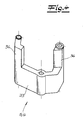
- Fig. 1 shows an embodiment of the inventive door hinge 1 for a concealed arrangement between the door frame 2 and door 3 with two receiving bodies 4, 4 ', a first hinge bracket 5 and a second hinge bracket 6, which are pivotally connected about a vertical connecting shaft 7.
- the receiving body 4, 4 ' are inserted into recesses in the door frame 2 and the door leaf 3 and each consist of a receiving part 8, 8' and adjustable inserts 9, 9 '.
- the inserts 9' by adjusting screws 10 in the horizontal direction in the receiving part 8 'can be adjusted (direction X).
- the inserts 9 in the vertical direction (Z) are adjustable.
- the receiving body 4, 4 ' have for attachment to the door 3 and on the door frame 2 holes 13.
- Fig. 2a to 2e show a door 3, which is posted by means of the door hinge 1 on the door frame 2.
- door frame 2 and the edge of the door leaf 3 are constructed of hollow sections 14, wherein the profiles of the door leaf 3 and the door frame 2 overlap at a door closed position in overlapping areas 15.
- a seal 16 is provided in each of the overlapping areas 15.
- the receiving body 4, 4 ' are arranged in recesses 17, 17' in the door leaf 3 and in the door frame 2.
- the first hinge bracket 5 is mounted about a first vertical axis of rotation 18 in the tzargen solutionen receiving body 4.
- the other end of the first hinge bracket 5 is rotatably mounted about a second vertical axis of rotation 19 in the door leaf-side receiving body 4 '.
- the first hinge bracket 5 thus forms with the two receiving bodies 4, 4 'a double joint.
- the second hinge bracket 6 is pivotally connected to the first hinge bracket 5 about a vertical connecting shaft 7.
- the second hinge bracket 6 is slidably and rotatably mounted at both ends in each case in S-shaped guide recesses 20, 20 ', wherein the shape of the guide recesses 20, 20' predetermines the movement of the door leaf 3 during the pivoting movement.
- the guide recesses 20, 20 ' are formed such that the end of the second hinge bracket 6 is guided in a first pivoting range of at least 60 degrees in the guide recesses 20 of the tzargen solutionen receiving body 4 in a circular arc about the first vertical axis of rotation 18.
- first pivoting range the angle between the first hinge bracket 5 and the second hinge bracket 6 remains the same.
- a rotation about the second vertical axis of rotation 19 is not possible because the distance between the ends of the hinge bracket 5, 6 and thus the relative angle between the first hinge bracket 5 and the second hinge bracket 6 would have to change.
- Fig. 2c shown intermediate range of a maximum of 60 degrees, in which both ends of the second hinge bracket 6 slide in the associated guide recesses 20, 20 '.
- the course of the guide recesses 20 in the tarmac side receiving body 4 in the direction of pivotal movement of a left turn at a turning point in a right bend over.
- the door-leaf-side end of the second hinge bracket 6 releases from a stop position 21 and slides in the associated recesses 20 '.
- Fig. 2d is shown, in addition slides the Matzargen worne end of the second Hinge bracket 6 to the end of the associated guide recesses 4 and suggests there.
- the intermediate region is followed by a second pivoting range of at least 60 degrees, the door-leaf-side end of the second hinge strap 6 being guided on a circular arc in the associated guide recesses 20 'about the second vertical axis of rotation 19.
- the first hinge bracket 5 rotates about the second vertical axis of rotation 19 and not about the first vertical axis of rotation 18. After a complete pivoting movement of the door leaf 3 reaches at an opening angle of 180 degrees its in Fig. 2e illustrated end position.
- FIG. 3 A possible construction of the door hinge 1 is in Fig. 3 shown.
- the receptacles 22 for the vertical axes of rotation 18, 19 of the first hinge bracket 5 are arranged such that in a central mounting of the door hinge 1 relative to the thickness direction of the door frame 2 and the door leaf 3, the vertical axes of rotation 18, 19 are shifted in the direction in the door 3 swings open.
- the inserts 9 of a receiving body 4 are fixed with fixing screws 11 through slots 12 on the receiving part 8 and can be fixed in different vertical positions.
- the inserts 9 'of the other receiving body 4' are adjustable with an adjusting device 23 which comprises an adjusting screw 10 and a locking washer 24 in the horizontal direction X relative to the receiving part 8 '.
- the H-shaped first hinge bracket 5 is mounted with bearing bushes 25 and pins 26, 26 'in the receptacles 22 for the vertical axes of rotation 18, 19 of the inserts 9, 9'.
- the first H-shaped hinge bracket 5 is with its middle Section disposed between the two fork arms 27 of the second, fork-shaped hinge bracket 6 and connected via a pin 28 about a vertical connecting axis 7 pivotally connected thereto.
- the second, fork-shaped hinge bracket 6 is constructed in three parts, wherein the horizontally extending fork arms 27 are connected at one of its ends by a vertical end portion which is formed by a spacer sleeve 29.
- the second hinge bracket 6 is slidably and rotatably mounted on sliding pins 30, 30 'in the S-shaped guide recesses 20, 20', wherein the sliding pins 30, 30 'liners 31, with which the sliding pins 30, 30' in the guide recesses 20, 20 'slide.
- the material of the bushings 31 belonging to the sliding pins 30, 30 ' differs from the material of the guide recesses 20, 20' surrounding the sliding pins 30, 30 ', friction being reduced by the specific choice of the different materials.
- the guide recesses 20, 20 ' may have special coatings or liners.
- the receiving body 4, 4 ' have holes 13 for fixing the door hinge 1 on the door frame 2 and on the door leaf 3, wherein in the region of the holes 13 shims 32 between the receiving bodies 4, 4' and the door 3 and the Moszarge second are provided. By using shims 32, the sound insulation and the temperature insulation can be improved.
- the hinge bracket 5, 6 are formed as injection molded plastic or metal. It is also possible to produce the hinge bracket 5, 6 as extruded profiles.
- Fig. 4 an alternative embodiment of the hinge bracket 5, 6 of the door hinge 1 is shown.
- the first hinge bracket 5 and the second hinge bracket 6 are designed as identical connecting elements and have a U-shape, each with a horizontally extending connecting web 33 and two vertically aligned legs 34.
- the Hinge bracket 5, 6 can be brought together in the manner of a connector and rotatably connected to the connecting webs 33.
Abstract
Description
Die Erfindung betrifft ein Türband für eine verdeckte Anordnung zwischen Türzarge und Türflügel mit zwei Aufnahmekörpern, die in Ausnehmungen im Türflügel und in der Zarge einsetzbar sind und einem ersten Schamierbügel und einem zweiten Schamierbügel, die um eine vertikale Verbindungsachse schwenkbeweglich verbunden sind.The invention relates to a door hinge for a concealed arrangement between the door frame and door with two receiving bodies, which are insertable into recesses in the door and in the frame and a first hinge and a second hinge, which are pivotally connected about a vertical connecting axis.
Ein Türband mit den eingangs beschriebenen Merkmalen ist aus
Aus der
Der Erfindung liegt die Aufgabe zugrunde, ein Türband zwischen Türzarge und Türflügel für die verdeckte Anordnung anzugeben, bei dem sich der Drehpunkt abhängig von dem Schwenkwinkel in einer vorgegebenen Weise ändert. Das Türband soll insbesondere für Türen mit in Türschließstellung sich überlappenden Türflügel- und Türzargenprofilen einsetzbar sein.The invention has for its object to provide a door hinge between the door frame and door for the concealed arrangement in which the pivot point changes depending on the tilt angle in a predetermined manner. The door hinge should be used in particular for doors with door closing position overlapping door leaf and door frame profiles.
Die Aufgabe wird erfindungsgemäß durch ein Türband gemäß Patentanspruch 1 gelöst. Durch die Gestaltung der Form der Scharnierbügel, die Positionierung der ersten und zweiten vertikalen Drehachse sowie insbesondere durch die Ausformung der Führungsausnehmungen kann der Verlauf einer Schwenkbewegung des erfindungsgemäßen Türbandes vielseitig variiert werden. Erfindungsgemäß gibt der S-förmige Verlauf der Führungsausnehmungen die Bewegung des Türflügels bei der Schwenkbewegung dergestalt vor, dass die gesamte Schwenkbewegung nacheinander Schwenkbereiche durchläuft, in denen unterschiedliche Bewegungen ausgeführt werden. Dabei wird der Bewegungsablauf durch die Form der Führungsausnehmungen so vorgegeben, dass die Verbindungsachse in einem der Schwenkbereiche, welcher mindestens 60 Grad groß ist, um eine vertikale Drehachse des ersten Scharnierbügels schwenkt und in einem anderen Schwenkbereich, welcher mindestens 60 Grad groß ist, ihre räumliche Lage bezogen auf die Türzarge beibehält. Eine solche Bewegung der Verbindungsachse kann dadurch erreicht werden, dass sich der erste Schamierbügel ausgehend von der Türschließstellung in einem ersten Schwenkbereich von mindestens 60 Grad um die erste und nicht um die zweite vertikale Drehachse dreht und dass ein zweiter Schwenkbereich von mindestens 60 Grad vorgesehen ist, in dem sich der erste Scharnierbügel um die zweite und nicht um die erste vertikale Drehachse dreht. Dieser Bewegungsablauf ist auf einfache Weise dadurch zu realisieren, dass in dem ersten Schwenkbereich ein Ende des zweiten Scharnierbügels in den Führungsausnehmungen des der ersten vertikalen Drehachse zugeordneten Aufnahmekörpers in einem Kreisbogen um die erste vertikale Drehachse geführt ist und dass in dem zweiten Schwenkbereich das andere Ende des zweiten Schamierbügels in den Führungsausnehmungen des anderen Aufnahmekörpers ebenfalls in einem Kreisbogen um die zweite vertikale Drehachse geführt ist. Das Türband ist so auch für Türen mit in Türschließstellung sich überlappenden Türflügel- und Türzargenprofilen einsetzbar, da die Schwenkbewegung durch die Form der Führungsausnehmungen so zu gestalten ist, dass sich der Türflügel zunächst in Dickenrichtung von dem Übehappungsbereich abhebt, bevor er gedreht wird.The object is achieved by a door hinge according to
Der erste und der zweite Scharnierbügel erfüllen unterschiedliche Funktionen. Die Verbindung der zwei Aufnahmekörper durch den ersten Scharnierbügel bildet ein Doppelgelenk, welches sich frei um die erste und zweite vertikale Drehachse in einem Bewegungsraum mit zwei Freiheitsgraden bewegen könnte, wenn der zweite Scharnierbügel nicht vorgesehen wäre. Durch den zweiten Scharnierbügel und die Form der Führungsausnehmungen der Aufnahmekörper wird innerhalb des Bewegungsraumes der Bewegungsablauf kinematisch festgelegt. Es versteht sich, dass die Form der Führungsausnehmungen eines Aufnahmekörpers auf die Form der Führungsausnehmungen des anderen Aufnahmekörpers abzustimmen ist.The first and the second hinge bracket fulfill different functions. The connection of the two receiving bodies through the first hinge bracket forms a double joint which could freely move about the first and second vertical axes of rotation in a space of movement with two degrees of freedom, if the second hinge bracket were not provided. By the second hinge bracket and the shape of the guide recesses of the receiving body of the motion sequence is determined kinematically within the movement space. It is understood that the shape of the guide recesses of a receiving body is to be adapted to the shape of the guide recesses of the other receiving body.
Mit dem erfindungsgemäßen Türband können ohne weiteres Öffnungswinkel bis 180 Grad erreicht werden, wobei die Schwenkbewegung in eine Abfolge unterschiedlicher Bewegungsabläufe aufgeteilt ist.With the door hinge according to the invention can be achieved without further opening angle up to 180 degrees, the pivoting movement is divided into a sequence of different movements.
Zwischen dem ersten und dem zweiten Schwenkbereich ist vorzugsweise ein Zwischenbereich von maximal 60 Grad vorgesehen, in dem beide Enden des zweiten Schamierbügels gleichzeitig in den zugeordneten Führungsausnehmungen gleiten. Ein solcher Zwischenbereich kann verwirklicht werden, indem sich in den Abschnitten der Führungsausnehmungen, in denen die Enden des zweiten Scharnierbügels gleichzeitig in dem Zwischenbereich gleiten, die Krümmungsrichtungen entlang der Bahnen der gleitenden Enden ändern, womit der Verlauf der Führungsausnehmungen folglich einen Wendepunkt aufweist. Bei einem solchen S-förmigen Verlauf gleitet das Ende des zweiten Scharnierbügels, welches dem Aufnahmekörper mit der ersten vertikalen Drehachse zugeordnet ist, bis zum Ende der Führungsausnehmung in der es geführt ist und schlägt dort an, wobei das andere Ende des zweiten Scharnierbügels eine Anschlagsposition verlässt und in den zugeordneten Führungsausnehmungen des anderen Aufnahmekörpers gleitet.Between the first and the second pivoting region, an intermediate region of at most 60 degrees is preferably provided, in which both ends of the second hinge strap slide simultaneously in the associated guide recesses. Such an intermediate area can be realized in that in the sections of the guide recesses in which the ends of the second hinge bracket slide simultaneously in the intermediate region, the directions of curvature change along the tracks of the sliding ends, whereby the course of the guide recesses consequently has a point of inflection. In such an S-shaped course, the end of the second hinge bracket, which is associated with the receiving body with the first vertical axis of rotation slides to the end of the guide recess in which it is guided and strikes there, the other end of the second hinge bracket leaves a stop position and slides in the associated guide recesses of the other receiving body.
Vorzugsweise ist bei den zuvor beschriebenen Ausführungen die erste vertikale Drehachse dem türzargenseitigen Aufnahmekörper zugeordnet. Schwenkt so der erste Scharnierbügel in einem ersten Schwenkbereich um die erste vertikale Drehachse, wird der Türflügel während des ersten Schwenkbereiches von der Türzarge abgehoben, ohne sich gegenüber dem ersten Scharnierbügel zu verdrehen.Preferably, in the embodiments described above, the first vertical axis of rotation is assigned to the door frame side receiving body. So pivots the first hinge bracket in a first pivoting area about the first vertical axis of rotation, the door is lifted during the first pivoting range of the door frame, without turning relative to the first hinge bracket.
Gemäß einer bevorzugten Ausführung der Erfindung ist die dem türzargenseitigen Aufnahmekörper zugeordnete vertikale Drehachse bezüglich der Mitte der Türzarge in deren Dickenrichtung verschoben, und zwar in die Richtung, in die der Türflügel aufschwenkt. Zusätzlich oder alternativ kann auch die dem türflügelseitigen Aufnahmekörper zugeordnete vertikale Drehachse bezüglich der Mitte des Türflügels in dessen Dickenrichtung verschoben sein, und zwar in die Richtung, in die der Türflügel aufschwenkt. Durch die Positionierung der ersten und der zweiten vertikalen Drehachse wird der räumliche Verlauf des Drehpunktes bezogen auf die Türzarge und den Türflügel festgelegt. Eine Verschiebung der Drehachsen in die Richtung, in die der Türflügel aufschwenkt, gewährleistet einerseits, dass sich bei einer mit einem Öffnungswinkel von 180 Grad geöffneten Tür ein Spalt zwischen Türzarge und Türflügel bildet und andererseits, dass der Drehpunkt bei der gesamten Schwenkbewegung weit genug von der Türzarge entfernt liegt, um ein Verklemmen von Türflügel und Türzarge zu verhindern.According to a preferred embodiment of the invention, the turzargenseitigen receiving body associated vertical axis of rotation with respect to the center of the door frame is moved in the thickness direction, in the direction in which the door swings open. Additionally or alternatively, the vertical axis of rotation associated with the door leaf-side receiving body may be displaced in the thickness direction with respect to the center of the door leaf, in the direction in which the door leaf swings open. By positioning the first and the second vertical axis of rotation of the spatial course of the pivot point is determined based on the door frame and the door leaf. A displacement of the axes of rotation in the direction in which the door swings open, on the one hand ensures that in a door with an opening angle of 180 degrees open a gap between the door frame and Door leaf forms and on the other hand, that the fulcrum in the entire pivoting movement is far enough away from the door frame to prevent jamming of the door leaf and door frame.
In einer bevorzugten Ausführung der Erfindung bestehen die Aufnahmekörper jeweils aus einem Aufnahmeteil und verstellbaren Einsätzen, wobei die Einsätze jeweils eine Führungsausnehmung sowie eine Aufnahme für eine vertikale Drehachse des ersten Scharnierbügels aufweisen. Die Einsätze können dabei derart ausgebildet sein, dass durch die Verstellung der Einsätze die Lage des Türflügels in vertikaler Richtung (Z), in horizontaler Dickenrichtung (Y) und/oder parallel zur horizontalen Ausrichtung des geschlossenen Türblattes (X) bezüglich der Türzarge einstellbar ist.In a preferred embodiment of the invention, the receiving body each consist of a receiving part and adjustable inserts, wherein the inserts each have a guide recess and a receptacle for a vertical axis of rotation of the first hinge bracket. The inserts can be designed such that the position of the door leaf in the vertical direction (Z), in the horizontal thickness direction (Y) and / or parallel to the horizontal orientation of the closed door leaf (X) with respect to the door frame is adjustable by the adjustment of the inserts.
Um die dauerhafte Funktionsfähigkeit des Türbandes zu gewährleisten, können Maßnahmen getroffen werden, um den Verschleiß durch Reibung zu reduzieren. Im Rahmen dieser Maßnahmen kann der zweite Scharnierbügel an Gleitstiften in den Führungsausnehmungen verschiebbar und drehbeweglich gelagert sein, wobei sich das Material A, welches die Gleitstifte im Bereich der Führungsausnehmungen umgibt, von dem Oberflächenmaterial B der Gleitstifte unterscheidet. Durch eine geeignete Materialkombination A-B kann der Verschleiß durch Reibung reduziert werden.In order to ensure the lasting functioning of the door hinge, measures can be taken to reduce wear due to friction. As part of these measures, the second hinge bracket can be slidably and rotatably mounted on sliding pins in the guide recesses, wherein the material A, which surrounds the sliding pins in the region of the guide recesses, differs from the surface material B of the sliding pins. By a suitable combination of materials A-B wear by friction can be reduced.
Im Rahmen der Erfindung können unterschiedliche Gestaltungen der Scharnierbügel, die vorzugsweise als Gussteile aus Kunststoff oder Metall ausgebildet sind, verwirklicht werden. In einer bevorzugten Ausführung der Erfindung ist einer der Scharnierbügel H-förmig und der andere Scharnierbügel gabelförmig ausgebildet, wobei der H-förmige Scharnierbügel mit seinem mittleren Abschnitt zwischen den zwei Gabelarmen des anderen, gabelförmigen Scharnierbügels angeordnet ist und wobei die Gabelarme des anderen Scharnierbügels an einem ihrer Enden durch einen vertikalen Abschnitt verbunden sind. Der H-förmige Scharnierbügel ist an seinem mittleren Abschnitt um eine vertikale Verbindungsachse schwenkbeweglich mit den Gabelarmen des anderen, gabelförmigen Scharnierbügels verbunden.In the context of the invention, different designs of the hinge bracket, which are preferably designed as castings made of plastic or metal, can be realized. In a preferred embodiment of the invention, one of the hinge bracket H-shaped and the other hinge bracket is fork-shaped, wherein the H-shaped hinge bracket is disposed with its central portion between the two fork arms of the other fork-shaped hinge bracket and wherein the fork arms of the other hinge bracket at a their ends through a vertical section are connected. The H-shaped hinge bracket is pivotally connected at its central portion about a vertical connecting axis with the fork arms of the other, forked hinge bracket.
Gemäß einer anderen, ebenfalls vorteilhaften Ausführung der Erfindung sind der erste Scharnierbügel und der zweite Scharnierbügel als baugleiche Verbindungselemente ausgebildet und weisen eine U-Form mit jeweils einem horizontal verlaufenden Verbindungssteg und vertikal ausgerichteten Schenkeln auf. Beide Scharnierbügel sind nach Art einer Steckverbindung zusammengefügt und an den Verbindungsstegen drehbeweglich verbunden.According to another, likewise advantageous embodiment of the invention, the first hinge bracket and the second hinge bracket are designed as identical connecting elements and have a U-shape, each with a horizontally extending connecting web and vertically aligned legs. Both hinge brackets are assembled in the manner of a plug connection and rotatably connected to the connecting webs.
Vorzugsweise reichen die Scharnierbügel in vertikaler Richtung in den Bereichen, in denen sie in den Aufnahmekörpern gelagert sind, bis an den Aufnahmekörper heran. Eine solche Ausgestaltung der Scharnierbügel, die insbesondere auch bei den zuvor beschriebenen Ausgestaltungen der Scharnierbügel möglich ist, ermöglicht eine Lagerung der Scharnierbügel an kurzen Zapfen, ohne dass zwischen den Scharnierbügeln und Aufnahmekörpern ein größerer Freiraum zu überbrücken ist. Durch eine solche Ausgestaltung kann eine hohe Formstabilität und ein sehr geringes Spiel des Türbandes erreicht werden.Preferably, the hinge straps extend in the vertical direction in the areas in which they are mounted in the receiving bodies, zoom up to the receiving body. Such an embodiment of the hinge bracket, which is also possible in particular in the previously described embodiments of the hinge bracket, allows the hinge bracket to be mounted on short pins, without a larger clearance having to be bridged between the hinge straps and receiving bodies. By such an embodiment, a high dimensional stability and a very low clearance of the door hinge can be achieved.
Im Folgenden wird die Erfindung anhand einer lediglich ein Ausführungsbeispiel darstellenden Zeichnung ausführlich erläutert. Es zeigen schematisch:
- Fig. 1
- die Ansicht einer Ausführungsform des erfindungsgemäßen Türbandes in der Öffnungsposition,
- Fig. 2a bis Fig. 2e
- eine Schnittdarstellung verschiedener Winkelpositionen eines Türflügels, der mittels einer Ausführungsform des erfindungsgemäßen Türbandes mit einer Türzarge verbunden ist,
- Fig. 3
- eine Explosionsdarstellung einer Ausführungsform des erfindungsgemäßen Türbandes,
- Fig. 4
- eine alternative Ausgestaltung der Scharnierbügel.
- Fig. 1
- the view of an embodiment of the door hinge according to the invention in the open position,
- Fig. 2a to Fig. 2e
- a sectional view of various angular positions of a door leaf, which is connected by means of an embodiment of the door hinge according to the invention with a door frame,
- Fig. 3
- an exploded view of an embodiment of the door hinge according to the invention,
- Fig. 4
- an alternative embodiment of the hinge bracket.
Die
Wie in
An den ersten Schwenkbereich schließt der in
Auf den Zwischenbereich folgt ein zweiter Schwenkbereich von mindestens 60 Grad, wobei das türflügelseitige Ende des zweiten Scharnierbügels 6 auf einem Kreisbogen in den zugehörigen Führungsausnehmungen 20' um die zweite vertikale Drehachse 19 geführt wird. Der erste Scharnierbügel 5 dreht sich dabei um die zweite vertikale Drehachse 19 und nicht um die erste vertikale Drehachse 18. Nach einer vollständigen Schwenkbewegung erreicht der Türflügel 3 bei einem Öffnungswinkel von 180 Grad seine in
Ein möglicher Aufbau des Türbandes 1 ist in
In
Claims (14)
- Door hinge for a concealed arrangement between a door case (2) and a door wing (3), withtwo receiving bodies (4, 4') which can be inserted into recesses (17, 17') in the door wing (3) and in the door case (2),a first hinge bracket (5) and a second hinge bracket (6), which are connected such that they can pivot about a vertical connection axis (7),wherein the first hinge bracket (5) is mounted at one end in one of the receiving bodies (4, 4') such that it can rotate about a first vertical axis of rotation (18) and at the other end in the other receiving body (4', 4) such that it can rotate about a second vertical axis of rotation (19), wherein the second hinge bracket (6) is mounted such that it can rotate and be displaced at each end in guide recesses (20, 20') of the receiving bodies (4, 4'),
wherein the S-shaped guide recesses (20, 20') define the movement of the door wing (3) during the pivoting movement in such a manner that the entire pivoting movement passes through pivot regions in which different movements are executed and that the connection axis (7) in one of the pivot regions, which is at least 60 degrees in size, pivots about one of the vertical axes of rotation (18, 19) of the first hinge bracket (5) and in another pivot region, which is at least 60 degrees in size, retains its spatial position in relation to the door case (2). - Door hinge according to Claim 1, characterised in that the first hinge bracket (5), starting from the door closed position, rotates in a first pivot region of at least 60 degrees about the first vertical axis of rotation (18) and not about the second vertical axis of rotation (19), and that a second pivot region of at least 60 degrees is provided, in which the first hinge bracket (5) rotates about the second vertical axis of rotation (19) and not about the first vertical axis of rotation (18).
- Door hinge according to Claim 2, characterised in that in the first pivot region, one of the ends of the second hinge bracket (6) is guided in the guide recesses (20) of the receiving body (4) associated with the first vertical axis of rotation (18) in an arc about the first vertical axis of rotation (18), and that in the second pivot region, the other end of the second hinge bracket (6) is guided in the guide recesses (20') of the other receiving body (4') in an arc about the second vertical axis of rotation (19).
- Door hinge according to Claim 2 or 3, characterised in that an intermediate region of no more than 60 degrees is provided between the first and second pivot regions, in which intermediate region both ends of the second hinge bracket (6) slide in the associated guide recesses (20, 20').
- Door hinge according to Claim 4, characterised in that the directions of curvature change along the paths of the sliding ends in the sections of the guide recesses (20, 20') in which the ends of the second hinge bracket (6) slide in the intermediate region, wherein during a pivoting movement in the intermediate region one of the ends of the second hinge bracket (6) slides as far as the end of the associated guide recesses (20) and comes to a stop there, and the other end of the second hinge bracket (6) leaves a stop position (21) and slides in the associated guide recesses (20').
- Door hinge according to one of Claims 1 to 5, characterised in that the first vertical axis of rotation (18) is associated with the door-case-side receiving body (4).
- Door hinge according to one of Claims 1 to 6, characterised in that the vertical axis of rotation (18) which is associated with the door-case-side receiving body (4) is displaced with respect to the centre of the door case (2) in the thickness direction of the latter, that is, in the direction in which the door wing (3) pivots open.
- Door hinge according to one of Claims 1 to 7, characterised in that the vertical axis of rotation (19) which is associated with the door-wing-side receiving body (4') is displaced with respect to the centre of the door wing (3) in the thickness direction of the latter, that is, in the direction in which the door wing (3) pivots open.
- Door hinge according to one of Claims 1 to 8, characterised in that the receiving bodies (4, 4') consist in each case of a receiving part (8, 8') and adjustable inserts (9, 9') and that the inserts (9, 9') in each case have a guide recess (20, 20') and a socket (22) for a vertical axis of rotation (18, 19) of the first hinge bracket (5).
- Door hinge according to Claim 9, characterised in that the inserts can be configured in such a manner that the position of the door wing (3) in the vertical direction (Z), in the horizontal direction (Y) and/or parallel to the horizontal alignment of the closed door panel (X) can be adjusted with respect to the door case (2) by adjusting the inserts (9, 9').
- Door hinge according to one of Claims 1 to 10, characterised in that the second hinge bracket (6) is mounted on sliding pins (30, 30') such that it can rotate and be displaced in the guide recesses (20, 20'), wherein the material (A) which surrounds the sliding pins (30, 30') in the region of the guide recesses (20, 20') differs from the surface material (B) of the sliding pins, and that wear as a result of friction is reduced by the A/B material combination in comparison to the A/A or B/B material combinations.
- Door hinge according to one of Claims 1 to 11, characterised in that one of the hinge brackets (5, 6) is H-shaped and the other hinge bracket (6, 5) is fork-shaped, wherein the H-shaped hinge bracket (5, 6) is arranged with its central section between the two fork arms (27) of the other, fork-shaped hinge bracket (6, 5), and wherein the fork arms (27) of the other hinge bracket (6, 5) are connected at one of their ends by a vertical end section.
- Door hinge according to one of Claims 1 to 11, characterised in that the first hinge bracket (5) and the second hinge bracket (6) are configured as structurally identical connection elements and have a U-shape with in each case one connection web (33) and vertically aligned limbs (34), and that both hinge brackets (5, 6) are joined together like a plugged connection and are connected to the connection webs (33) such that they can rotate.
- Door hinge according to one of Claims 1 to 13, characterised in that the hinge brackets (5, 6) are formed as cast parts consisting of plastic or metal.
Priority Applications (1)
| Application Number | Priority Date | Filing Date | Title |
|---|---|---|---|
| PL06010221T PL1754848T3 (en) | 2005-08-20 | 2006-05-18 | Door hinge for hidden assembly between door frame and door wing |
Applications Claiming Priority (1)
| Application Number | Priority Date | Filing Date | Title |
|---|---|---|---|
| DE102005039509A DE102005039509B3 (en) | 2005-08-20 | 2005-08-20 | Door hinge e.g. for masked assembly between door frame and case, has two adapter bodies positioned in recesses in frame and in door case with two hinge handles swivelinglly connected around vertical connecting axle |
Publications (3)
| Publication Number | Publication Date |
|---|---|
| EP1754848A2 EP1754848A2 (en) | 2007-02-21 |
| EP1754848A3 EP1754848A3 (en) | 2009-01-28 |
| EP1754848B1 true EP1754848B1 (en) | 2011-02-23 |
Family
ID=36571407
Family Applications (1)
| Application Number | Title | Priority Date | Filing Date |
|---|---|---|---|
| EP06010221A Not-in-force EP1754848B1 (en) | 2005-08-20 | 2006-05-18 | Door hinge for hidden assembly between door frame and door wing |
Country Status (5)
| Country | Link |
|---|---|
| EP (1) | EP1754848B1 (en) |
| JP (1) | JP2007056666A (en) |
| AT (1) | ATE499502T1 (en) |
| DE (2) | DE102005039509B3 (en) |
| PL (1) | PL1754848T3 (en) |
Families Citing this family (33)
| Publication number | Priority date | Publication date | Assignee | Title |
|---|---|---|---|---|
| DE102006062614C5 (en) * | 2006-12-29 | 2017-05-18 | Bartels Systembeschläge GmbH | Door hinge for rebated doors |
| DE102008027209B3 (en) | 2008-06-06 | 2009-07-16 | Simonswerk, Gesellschaft mit beschränkter Haftung | hinge |
| DE102008027219B3 (en) * | 2008-06-06 | 2009-07-16 | Simonswerk, Gesellschaft mit beschränkter Haftung | Door hinge for arrangement between door frame and welted door leaf, has door leaf support body exhibiting lateral, parallel offset to door frame support body in closing position in one direction, in which door is moved when opened |
| DE102008056327B3 (en) * | 2008-11-07 | 2010-04-15 | Simonswerk, Gesellschaft mit beschränkter Haftung | Door hinge for a concealed arrangement |
| DE102008057341B3 (en) * | 2008-11-14 | 2009-12-31 | Simonswerk, Gesellschaft mit beschränkter Haftung | Door hinge for concealed arrangement between door frame and door leaf |
| JP5331556B2 (en) * | 2009-04-23 | 2013-10-30 | パナソニック株式会社 | Door connecting member and door connecting structure using the same |
| JP4956676B2 (en) * | 2009-06-08 | 2012-06-20 | スガツネ工業株式会社 | Biaxial hinge device |
| IT1398175B1 (en) * | 2010-02-01 | 2013-02-14 | Oikos Venezia Srl | HINGE FOR DOORS, DOORS OR DOORS WITH HINGES IN GENERAL, WITH DISAPPEARANCE AND COMPLETE ROTATION |
| DE102010025691B3 (en) | 2010-06-30 | 2011-10-27 | Simonswerk, Gesellschaft mit beschränkter Haftung | Door hinge, in particular for hollow profile frames |
| DE102011000150B3 (en) * | 2011-01-14 | 2011-10-06 | Simonswerk, Gesellschaft mit beschränkter Haftung | Door hinge for convertible arrangement between door frame and door wing of door, has door wing-receiving body which is inserted in recess in narrow side of door wing |
| DE102011051190B3 (en) * | 2011-06-20 | 2012-07-26 | Emka Beschlagteile Gmbh & Co. Kg | Inboard 180 degree hinge for a row cabinet layout |
| ITTV20120105A1 (en) * | 2012-05-30 | 2013-12-01 | Anselmi & C Srl | HIDDEN HINGE FOR FURNITURE AND WINDOW DOORS |
| DE102013100231B3 (en) | 2013-01-10 | 2013-10-31 | Simonswerk, Gesellschaft mit beschränkter Haftung | Door hinge for use in door assembly, has adjustment element that is inserted into receiving space of door frame, to cause displacement of bearing insert portion from mounting position to operating position |
| DE102013106943B3 (en) * | 2013-07-02 | 2014-02-06 | Bernhard Stammschröer | Concealed door or flat band for e.g. wooden block, has control arms whose mutual spreading angle is limited with one another, such that pins are engaged in arc recesses of the respective adjacent control arms |
| GB2517754B8 (en) * | 2013-08-30 | 2020-08-19 | Howden Joinery Ltd | Furniture article |
| CZ2013969A3 (en) * | 2013-12-05 | 2015-04-22 | Tokoz A.S. | Blind hinge |
| DE202014007472U1 (en) | 2014-01-24 | 2015-01-16 | Lohr Technologies Gmbh | Hidden hinge |
| DE102015112647B3 (en) * | 2015-07-31 | 2016-01-21 | Simonswerk, Gesellschaft mit beschränkter Haftung | Door hinge for a concealed arrangement between the door leaf and the door frame |
| US10900265B2 (en) | 2015-10-12 | 2021-01-26 | Kuantica S.R.L. | Structurally improved invisible hidden door hinge with position adjustment |
| US20190071904A1 (en) | 2015-10-12 | 2019-03-07 | Kuantica S.R.L. | Structurally improved invisible concealed hinge for doors |
| ITUB20156253A1 (en) * | 2015-12-04 | 2017-06-04 | Dierre Spa | Concealed hinge |
| TWM538310U (en) * | 2016-11-29 | 2017-03-11 | First Dome Corp | Multi-link hinge |
| IT201800002662A1 (en) * | 2018-02-15 | 2019-08-15 | Otlav Spa | HINGING STRUCTURE FOR WINDOWS |
| GB2580139A (en) * | 2018-12-21 | 2020-07-15 | Aanco Uk Ltd | Hinge for folding doors |
| DE102019100538B3 (en) * | 2019-01-10 | 2020-03-05 | Simonswerk Gmbh | Building door and hinge |
| EP3683388A1 (en) * | 2019-01-15 | 2020-07-22 | Robert Peer | Hinge |
| CN114144563B (en) * | 2019-07-11 | 2023-09-05 | 世嘉智尼工业株式会社 | Hinge device |
| CN112444080B (en) * | 2019-08-28 | 2022-02-22 | 青岛海尔电冰箱有限公司 | Multi-door refrigerator capable of increasing opening degree |
| AT524068B1 (en) * | 2020-07-29 | 2023-01-15 | Peer Robert | hinge |
| CN112211515A (en) * | 2020-10-13 | 2021-01-12 | 广州市欧美嘉实业投资有限公司 | Three-dimensional adjustable heavy blind hinge of crack micro-gap |
| EP4148217A1 (en) | 2021-09-08 | 2023-03-15 | Robert Peer | Concealed hinge |
| CN115839585A (en) * | 2021-09-18 | 2023-03-24 | 海信(山东)冰箱有限公司 | Refrigerator with a door |
| DE102021129879B3 (en) | 2021-11-16 | 2023-01-26 | Simonswerk Gmbh | Door hinge with elongated guide carriage |
Family Cites Families (6)
| Publication number | Priority date | Publication date | Assignee | Title |
|---|---|---|---|---|
| US2040279A (en) * | 1935-06-08 | 1936-05-12 | Soss Joseph | Concealed hinge |
| GB445406A (en) * | 1935-10-11 | 1936-04-08 | Emil Benedict Gustav Lefevre | Improvements relating to hinges |
| US4242773A (en) * | 1978-08-17 | 1981-01-06 | Beigh Lauris L | Cabinet hinge |
| ATE451525T1 (en) * | 2001-10-31 | 2009-12-15 | Simonswerk Gmbh | DOOR HINGE FOR A CONCEALED ARRANGEMENT BETWEEN THE DOOR FRAME AND THE DOOR LEAF |
| DE20213155U1 (en) * | 2002-08-28 | 2002-11-14 | Simonswerk,Gmbh | Hinge for a concealed arrangement between the door frame and door leaf |
| DE102004012350B3 (en) * | 2004-03-11 | 2005-07-21 | Simonswerk, Gmbh | Door strip for covered fitting between door frame and door leaf has hinge yokes serving as connecting elements |
-
2005
- 2005-08-20 DE DE102005039509A patent/DE102005039509B3/en not_active Expired - Fee Related
-
2006
- 2006-05-18 PL PL06010221T patent/PL1754848T3/en unknown
- 2006-05-18 DE DE502006008939T patent/DE502006008939D1/en active Active
- 2006-05-18 EP EP06010221A patent/EP1754848B1/en not_active Not-in-force
- 2006-05-18 AT AT06010221T patent/ATE499502T1/en active
- 2006-08-17 JP JP2006222552A patent/JP2007056666A/en not_active Withdrawn
Also Published As
| Publication number | Publication date |
|---|---|
| EP1754848A3 (en) | 2009-01-28 |
| EP1754848A2 (en) | 2007-02-21 |
| DE102005039509B3 (en) | 2006-06-22 |
| ATE499502T1 (en) | 2011-03-15 |
| PL1754848T3 (en) | 2011-07-29 |
| DE502006008939D1 (en) | 2011-04-07 |
| JP2007056666A (en) | 2007-03-08 |
Similar Documents
| Publication | Publication Date | Title |
|---|---|---|
| EP1754848B1 (en) | Door hinge for hidden assembly between door frame and door wing | |
| EP1688568B1 (en) | Door, in particular for a motor vehicle | |
| EP1308592B1 (en) | Door hinge for hidden assembly between door frame and door hinge | |
| EP1574649B1 (en) | Door hinge for hidden assembly between door frame and door wing | |
| EP2504509B1 (en) | Concealed 180° hinge | |
| DE20023445U1 (en) | Hidden hinge for wings, e.g. doors, of furniture items has adjusters to vary position of fastening elements along at least one direction defined by at least one of three Cartesian axes | |
| DE10164979B4 (en) | Hidden door hinge for pivotally mounting a door leaf on a door frame | |
| AT506828B1 (en) | DOOR BAND FOR A COVERED ARRANGEMENT BETWEEN DOOR BRACKET AND SLIDING DOOR WING | |
| EP2540941A2 (en) | Concealed hinge for a door or similar components | |
| EP2130997B1 (en) | Door with a hinge | |
| EP1939381A2 (en) | Hinge for rabbeted doors | |
| DE102015222116B3 (en) | Ausstellscherenanordnung and sliding or sliding windows with such Ausstellscherenanordnung | |
| EP2642054A2 (en) | Hinge for a covered assembly between door frame and door wing | |
| DE202004004341U1 (en) | Hinge mechanism for connecting door leaf to door frame has first set of hinge bands with pivots in frame sliding in grooves in door leaf and second set of bands pivoting on leaf and sliding in frame | |
| DE102018100672A1 (en) | Furniture hinge, furniture panel and furniture body | |
| EP2476837A1 (en) | Hinge | |
| DE10301046B4 (en) | Swivel fitting for concealed arrangement on doors or windows | |
| EP1291481B1 (en) | Hinge | |
| DE3048334C2 (en) | ||
| DE2443036B2 (en) | Opening device | |
| DE102018119025B3 (en) | Hinge for the articulated connection of machine casing wall parts and / or machine doors | |
| EP1568839A2 (en) | Window or door | |
| EP2233669A2 (en) | Fitting device and window or door with same | |
| DE4227254C1 (en) | Hinged door hinge | |
| DE3139574A1 (en) | Actuating gear for espagnolette fittings or the like |
Legal Events
| Date | Code | Title | Description |
|---|---|---|---|
| PUAI | Public reference made under article 153(3) epc to a published international application that has entered the european phase |
Free format text: ORIGINAL CODE: 0009012 |
|
| AK | Designated contracting states |
Kind code of ref document: A2 Designated state(s): AT BE BG CH CY CZ DE DK EE ES FI FR GB GR HU IE IS IT LI LT LU LV MC NL PL PT RO SE SI SK TR |
|
| AX | Request for extension of the european patent |
Extension state: AL BA HR MK YU |
|
| PUAL | Search report despatched |
Free format text: ORIGINAL CODE: 0009013 |
|
| AK | Designated contracting states |
Kind code of ref document: A3 Designated state(s): AT BE BG CH CY CZ DE DK EE ES FI FR GB GR HU IE IS IT LI LT LU LV MC NL PL PT RO SE SI SK TR |
|
| AX | Request for extension of the european patent |
Extension state: AL BA HR MK YU |
|
| 17P | Request for examination filed |
Effective date: 20090206 |
|
| 17Q | First examination report despatched |
Effective date: 20090320 |
|
| AKX | Designation fees paid |
Designated state(s): AT BE BG CH CY CZ DE DK EE ES FI FR GB GR HU IE IS IT LI LT LU LV MC NL PL PT RO SE SI SK TR |
|
| GRAP | Despatch of communication of intention to grant a patent |
Free format text: ORIGINAL CODE: EPIDOSNIGR1 |
|
| GRAS | Grant fee paid |
Free format text: ORIGINAL CODE: EPIDOSNIGR3 |
|
| GRAA | (expected) grant |
Free format text: ORIGINAL CODE: 0009210 |
|
| AK | Designated contracting states |
Kind code of ref document: B1 Designated state(s): AT BE BG CH CY CZ DE DK EE ES FI FR GB GR HU IE IS IT LI LT LU LV MC NL PL PT RO SE SI SK TR |
|
| REG | Reference to a national code |
Ref country code: GB Ref legal event code: FG4D Free format text: NOT ENGLISH |
|
| REG | Reference to a national code |
Ref country code: CH Ref legal event code: EP |
|
| REG | Reference to a national code |
Ref country code: IE Ref legal event code: FG4D Free format text: LANGUAGE OF EP DOCUMENT: GERMAN |
|
| REF | Corresponds to: |
Ref document number: 502006008939 Country of ref document: DE Date of ref document: 20110407 Kind code of ref document: P |
|
| REG | Reference to a national code |
Ref country code: DE Ref legal event code: R096 Ref document number: 502006008939 Country of ref document: DE Effective date: 20110407 |
|
| REG | Reference to a national code |
Ref country code: CH Ref legal event code: NV Representative=s name: KELLER & PARTNER PATENTANWAELTE AG |
|
| REG | Reference to a national code |
Ref country code: NL Ref legal event code: T3 |
|
| LTIE | Lt: invalidation of european patent or patent extension |
Effective date: 20110223 |
|
| PG25 | Lapsed in a contracting state [announced via postgrant information from national office to epo] |
Ref country code: PT Free format text: LAPSE BECAUSE OF FAILURE TO SUBMIT A TRANSLATION OF THE DESCRIPTION OR TO PAY THE FEE WITHIN THE PRESCRIBED TIME-LIMIT Effective date: 20110623 Ref country code: LV Free format text: LAPSE BECAUSE OF FAILURE TO SUBMIT A TRANSLATION OF THE DESCRIPTION OR TO PAY THE FEE WITHIN THE PRESCRIBED TIME-LIMIT Effective date: 20110223 Ref country code: LT Free format text: LAPSE BECAUSE OF FAILURE TO SUBMIT A TRANSLATION OF THE DESCRIPTION OR TO PAY THE FEE WITHIN THE PRESCRIBED TIME-LIMIT Effective date: 20110223 Ref country code: GR Free format text: LAPSE BECAUSE OF FAILURE TO SUBMIT A TRANSLATION OF THE DESCRIPTION OR TO PAY THE FEE WITHIN THE PRESCRIBED TIME-LIMIT Effective date: 20110524 Ref country code: SE Free format text: LAPSE BECAUSE OF FAILURE TO SUBMIT A TRANSLATION OF THE DESCRIPTION OR TO PAY THE FEE WITHIN THE PRESCRIBED TIME-LIMIT Effective date: 20110223 Ref country code: ES Free format text: LAPSE BECAUSE OF FAILURE TO SUBMIT A TRANSLATION OF THE DESCRIPTION OR TO PAY THE FEE WITHIN THE PRESCRIBED TIME-LIMIT Effective date: 20110603 |
|
| REG | Reference to a national code |
Ref country code: PL Ref legal event code: T3 |
|
| PG25 | Lapsed in a contracting state [announced via postgrant information from national office to epo] |
Ref country code: BG Free format text: LAPSE BECAUSE OF FAILURE TO SUBMIT A TRANSLATION OF THE DESCRIPTION OR TO PAY THE FEE WITHIN THE PRESCRIBED TIME-LIMIT Effective date: 20110523 Ref country code: CY Free format text: LAPSE BECAUSE OF FAILURE TO SUBMIT A TRANSLATION OF THE DESCRIPTION OR TO PAY THE FEE WITHIN THE PRESCRIBED TIME-LIMIT Effective date: 20110223 Ref country code: FI Free format text: LAPSE BECAUSE OF FAILURE TO SUBMIT A TRANSLATION OF THE DESCRIPTION OR TO PAY THE FEE WITHIN THE PRESCRIBED TIME-LIMIT Effective date: 20110223 Ref country code: SI Free format text: LAPSE BECAUSE OF FAILURE TO SUBMIT A TRANSLATION OF THE DESCRIPTION OR TO PAY THE FEE WITHIN THE PRESCRIBED TIME-LIMIT Effective date: 20110223 |
|
| REG | Reference to a national code |
Ref country code: IE Ref legal event code: FD4D |
|
| PG25 | Lapsed in a contracting state [announced via postgrant information from national office to epo] |
Ref country code: IE Free format text: LAPSE BECAUSE OF FAILURE TO SUBMIT A TRANSLATION OF THE DESCRIPTION OR TO PAY THE FEE WITHIN THE PRESCRIBED TIME-LIMIT Effective date: 20110223 Ref country code: EE Free format text: LAPSE BECAUSE OF FAILURE TO SUBMIT A TRANSLATION OF THE DESCRIPTION OR TO PAY THE FEE WITHIN THE PRESCRIBED TIME-LIMIT Effective date: 20110223 Ref country code: DK Free format text: LAPSE BECAUSE OF FAILURE TO SUBMIT A TRANSLATION OF THE DESCRIPTION OR TO PAY THE FEE WITHIN THE PRESCRIBED TIME-LIMIT Effective date: 20110223 |
|
| PG25 | Lapsed in a contracting state [announced via postgrant information from national office to epo] |
Ref country code: SK Free format text: LAPSE BECAUSE OF FAILURE TO SUBMIT A TRANSLATION OF THE DESCRIPTION OR TO PAY THE FEE WITHIN THE PRESCRIBED TIME-LIMIT Effective date: 20110223 Ref country code: RO Free format text: LAPSE BECAUSE OF FAILURE TO SUBMIT A TRANSLATION OF THE DESCRIPTION OR TO PAY THE FEE WITHIN THE PRESCRIBED TIME-LIMIT Effective date: 20110223 |
|
| PG25 | Lapsed in a contracting state [announced via postgrant information from national office to epo] |
Ref country code: MC Free format text: LAPSE BECAUSE OF NON-PAYMENT OF DUE FEES Effective date: 20110531 |
|
| PLBE | No opposition filed within time limit |
Free format text: ORIGINAL CODE: 0009261 |
|
| STAA | Information on the status of an ep patent application or granted ep patent |
Free format text: STATUS: NO OPPOSITION FILED WITHIN TIME LIMIT |
|
| 26N | No opposition filed |
Effective date: 20111124 |
|
| REG | Reference to a national code |
Ref country code: DE Ref legal event code: R097 Ref document number: 502006008939 Country of ref document: DE Effective date: 20111124 |
|
| PG25 | Lapsed in a contracting state [announced via postgrant information from national office to epo] |
Ref country code: LU Free format text: LAPSE BECAUSE OF NON-PAYMENT OF DUE FEES Effective date: 20110518 |
|
| PG25 | Lapsed in a contracting state [announced via postgrant information from national office to epo] |
Ref country code: IS Free format text: LAPSE BECAUSE OF FAILURE TO SUBMIT A TRANSLATION OF THE DESCRIPTION OR TO PAY THE FEE WITHIN THE PRESCRIBED TIME-LIMIT Effective date: 20110223 |
|
| PG25 | Lapsed in a contracting state [announced via postgrant information from national office to epo] |
Ref country code: TR Free format text: LAPSE BECAUSE OF FAILURE TO SUBMIT A TRANSLATION OF THE DESCRIPTION OR TO PAY THE FEE WITHIN THE PRESCRIBED TIME-LIMIT Effective date: 20110223 |
|
| PG25 | Lapsed in a contracting state [announced via postgrant information from national office to epo] |
Ref country code: HU Free format text: LAPSE BECAUSE OF FAILURE TO SUBMIT A TRANSLATION OF THE DESCRIPTION OR TO PAY THE FEE WITHIN THE PRESCRIBED TIME-LIMIT Effective date: 20110223 |
|
| REG | Reference to a national code |
Ref country code: CH Ref legal event code: PCAR Free format text: NEW ADDRESS: EIGERSTRASSE 2 POSTFACH, 3000 BERN 14 (CH) |
|
| REG | Reference to a national code |
Ref country code: FR Ref legal event code: PLFP Year of fee payment: 11 |
|
| REG | Reference to a national code |
Ref country code: FR Ref legal event code: PLFP Year of fee payment: 12 |
|
| REG | Reference to a national code |
Ref country code: FR Ref legal event code: PLFP Year of fee payment: 13 |
|
| PGFP | Annual fee paid to national office [announced via postgrant information from national office to epo] |
Ref country code: CH Payment date: 20200520 Year of fee payment: 15 Ref country code: CZ Payment date: 20200518 Year of fee payment: 15 Ref country code: FR Payment date: 20200522 Year of fee payment: 15 Ref country code: NL Payment date: 20200527 Year of fee payment: 15 |
|
| PGFP | Annual fee paid to national office [announced via postgrant information from national office to epo] |
Ref country code: PL Payment date: 20200508 Year of fee payment: 15 Ref country code: GB Payment date: 20200527 Year of fee payment: 15 Ref country code: BE Payment date: 20200527 Year of fee payment: 15 Ref country code: IT Payment date: 20200528 Year of fee payment: 15 |
|
| PGFP | Annual fee paid to national office [announced via postgrant information from national office to epo] |
Ref country code: AT Payment date: 20200522 Year of fee payment: 15 |
|
| REG | Reference to a national code |
Ref country code: CH Ref legal event code: PFA Owner name: SIMONSWERK, GESELLSCHAFT MIT BESCHRAENKTER HAF, DE Free format text: FORMER OWNER: SIMONSWERK, GESELLSCHAFT MIT BESCHRAENKTER HAFTUNG, DE |
|
| REG | Reference to a national code |
Ref country code: CH Ref legal event code: PL |
|
| REG | Reference to a national code |
Ref country code: NL Ref legal event code: MM Effective date: 20210601 |
|
| REG | Reference to a national code |
Ref country code: AT Ref legal event code: MM01 Ref document number: 499502 Country of ref document: AT Kind code of ref document: T Effective date: 20210518 |
|
| GBPC | Gb: european patent ceased through non-payment of renewal fee |
Effective date: 20210518 |
|
| PG25 | Lapsed in a contracting state [announced via postgrant information from national office to epo] |
Ref country code: AT Free format text: LAPSE BECAUSE OF NON-PAYMENT OF DUE FEES Effective date: 20210518 Ref country code: CH Free format text: LAPSE BECAUSE OF NON-PAYMENT OF DUE FEES Effective date: 20210531 Ref country code: LI Free format text: LAPSE BECAUSE OF NON-PAYMENT OF DUE FEES Effective date: 20210531 Ref country code: CZ Free format text: LAPSE BECAUSE OF NON-PAYMENT OF DUE FEES Effective date: 20210518 |
|
| REG | Reference to a national code |
Ref country code: BE Ref legal event code: MM Effective date: 20210531 |
|
| PG25 | Lapsed in a contracting state [announced via postgrant information from national office to epo] |
Ref country code: GB Free format text: LAPSE BECAUSE OF NON-PAYMENT OF DUE FEES Effective date: 20210518 |
|
| PG25 | Lapsed in a contracting state [announced via postgrant information from national office to epo] |
Ref country code: NL Free format text: LAPSE BECAUSE OF NON-PAYMENT OF DUE FEES Effective date: 20210601 Ref country code: FR Free format text: LAPSE BECAUSE OF NON-PAYMENT OF DUE FEES Effective date: 20210531 |
|
| PG25 | Lapsed in a contracting state [announced via postgrant information from national office to epo] |
Ref country code: BE Free format text: LAPSE BECAUSE OF NON-PAYMENT OF DUE FEES Effective date: 20210531 |
|
| PGFP | Annual fee paid to national office [announced via postgrant information from national office to epo] |
Ref country code: DE Payment date: 20220511 Year of fee payment: 17 |
|
| PG25 | Lapsed in a contracting state [announced via postgrant information from national office to epo] |
Ref country code: PL Free format text: LAPSE BECAUSE OF NON-PAYMENT OF DUE FEES Effective date: 20210518 |
|
| PG25 | Lapsed in a contracting state [announced via postgrant information from national office to epo] |
Ref country code: IT Free format text: LAPSE BECAUSE OF NON-PAYMENT OF DUE FEES Effective date: 20200518 |
|
| REG | Reference to a national code |
Ref country code: DE Ref legal event code: R119 Ref document number: 502006008939 Country of ref document: DE |