EP1754622A1 - Vehicle information display device and vehicle information display method - Google Patents
Vehicle information display device and vehicle information display method Download PDFInfo
- Publication number
- EP1754622A1 EP1754622A1 EP05719205A EP05719205A EP1754622A1 EP 1754622 A1 EP1754622 A1 EP 1754622A1 EP 05719205 A EP05719205 A EP 05719205A EP 05719205 A EP05719205 A EP 05719205A EP 1754622 A1 EP1754622 A1 EP 1754622A1
- Authority
- EP
- European Patent Office
- Prior art keywords
- display
- image
- information
- display image
- vehicle information
- Prior art date
- Legal status (The legal status is an assumption and is not a legal conclusion. Google has not performed a legal analysis and makes no representation as to the accuracy of the status listed.)
- Withdrawn
Links
- 238000000034 method Methods 0.000 title claims abstract description 32
- 230000008859 change Effects 0.000 claims abstract description 19
- 230000009467 reduction Effects 0.000 claims abstract description 9
- 230000008569 process Effects 0.000 abstract description 15
- 238000003384 imaging method Methods 0.000 description 9
- 239000000446 fuel Substances 0.000 description 6
- 239000004973 liquid crystal related substance Substances 0.000 description 4
- 230000004048 modification Effects 0.000 description 4
- 238000012986 modification Methods 0.000 description 4
- 229920003002 synthetic resin Polymers 0.000 description 3
- 239000000057 synthetic resin Substances 0.000 description 3
- 239000010409 thin film Substances 0.000 description 3
- 230000008021 deposition Effects 0.000 description 2
- 238000010586 diagram Methods 0.000 description 2
- 239000010408 film Substances 0.000 description 2
- 239000000463 material Substances 0.000 description 2
- XLYOFNOQVPJJNP-UHFFFAOYSA-N water Substances O XLYOFNOQVPJJNP-UHFFFAOYSA-N 0.000 description 2
- 230000002159 abnormal effect Effects 0.000 description 1
- 230000005540 biological transmission Effects 0.000 description 1
- 230000007812 deficiency Effects 0.000 description 1
- 230000000694 effects Effects 0.000 description 1
- 238000005401 electroluminescence Methods 0.000 description 1
- 239000002828 fuel tank Substances 0.000 description 1
- 239000011521 glass Substances 0.000 description 1
- 230000006872 improvement Effects 0.000 description 1
- 230000010365 information processing Effects 0.000 description 1
- 230000004297 night vision Effects 0.000 description 1
Images


Classifications
-
- B—PERFORMING OPERATIONS; TRANSPORTING
- B60—VEHICLES IN GENERAL
- B60K—ARRANGEMENT OR MOUNTING OF PROPULSION UNITS OR OF TRANSMISSIONS IN VEHICLES; ARRANGEMENT OR MOUNTING OF PLURAL DIVERSE PRIME-MOVERS IN VEHICLES; AUXILIARY DRIVES FOR VEHICLES; INSTRUMENTATION OR DASHBOARDS FOR VEHICLES; ARRANGEMENTS IN CONNECTION WITH COOLING, AIR INTAKE, GAS EXHAUST OR FUEL SUPPLY OF PROPULSION UNITS IN VEHICLES
- B60K35/00—Instruments specially adapted for vehicles; Arrangement of instruments in or on vehicles
- B60K35/20—Output arrangements, i.e. from vehicle to user, associated with vehicle functions or specially adapted therefor
- B60K35/21—Output arrangements, i.e. from vehicle to user, associated with vehicle functions or specially adapted therefor using visual output, e.g. blinking lights or matrix displays
- B60K35/213—Virtual instruments
-
- B—PERFORMING OPERATIONS; TRANSPORTING
- B60—VEHICLES IN GENERAL
- B60K—ARRANGEMENT OR MOUNTING OF PROPULSION UNITS OR OF TRANSMISSIONS IN VEHICLES; ARRANGEMENT OR MOUNTING OF PLURAL DIVERSE PRIME-MOVERS IN VEHICLES; AUXILIARY DRIVES FOR VEHICLES; INSTRUMENTATION OR DASHBOARDS FOR VEHICLES; ARRANGEMENTS IN CONNECTION WITH COOLING, AIR INTAKE, GAS EXHAUST OR FUEL SUPPLY OF PROPULSION UNITS IN VEHICLES
- B60K35/00—Instruments specially adapted for vehicles; Arrangement of instruments in or on vehicles
- B60K35/20—Output arrangements, i.e. from vehicle to user, associated with vehicle functions or specially adapted therefor
- B60K35/29—Instruments characterised by the way in which information is handled, e.g. showing information on plural displays or prioritising information according to driving conditions
-
- B—PERFORMING OPERATIONS; TRANSPORTING
- B60—VEHICLES IN GENERAL
- B60K—ARRANGEMENT OR MOUNTING OF PROPULSION UNITS OR OF TRANSMISSIONS IN VEHICLES; ARRANGEMENT OR MOUNTING OF PLURAL DIVERSE PRIME-MOVERS IN VEHICLES; AUXILIARY DRIVES FOR VEHICLES; INSTRUMENTATION OR DASHBOARDS FOR VEHICLES; ARRANGEMENTS IN CONNECTION WITH COOLING, AIR INTAKE, GAS EXHAUST OR FUEL SUPPLY OF PROPULSION UNITS IN VEHICLES
- B60K35/00—Instruments specially adapted for vehicles; Arrangement of instruments in or on vehicles
- B60K35/60—Instruments characterised by their location or relative disposition in or on vehicles
-
- B—PERFORMING OPERATIONS; TRANSPORTING
- B60—VEHICLES IN GENERAL
- B60K—ARRANGEMENT OR MOUNTING OF PROPULSION UNITS OR OF TRANSMISSIONS IN VEHICLES; ARRANGEMENT OR MOUNTING OF PLURAL DIVERSE PRIME-MOVERS IN VEHICLES; AUXILIARY DRIVES FOR VEHICLES; INSTRUMENTATION OR DASHBOARDS FOR VEHICLES; ARRANGEMENTS IN CONNECTION WITH COOLING, AIR INTAKE, GAS EXHAUST OR FUEL SUPPLY OF PROPULSION UNITS IN VEHICLES
- B60K35/00—Instruments specially adapted for vehicles; Arrangement of instruments in or on vehicles
- B60K35/65—Instruments specially adapted for specific vehicle types or users, e.g. for left- or right-hand drive
- B60K35/654—Instruments specially adapted for specific vehicle types or users, e.g. for left- or right-hand drive the user being the driver
-
- B—PERFORMING OPERATIONS; TRANSPORTING
- B60—VEHICLES IN GENERAL
- B60K—ARRANGEMENT OR MOUNTING OF PROPULSION UNITS OR OF TRANSMISSIONS IN VEHICLES; ARRANGEMENT OR MOUNTING OF PLURAL DIVERSE PRIME-MOVERS IN VEHICLES; AUXILIARY DRIVES FOR VEHICLES; INSTRUMENTATION OR DASHBOARDS FOR VEHICLES; ARRANGEMENTS IN CONNECTION WITH COOLING, AIR INTAKE, GAS EXHAUST OR FUEL SUPPLY OF PROPULSION UNITS IN VEHICLES
- B60K2360/00—Indexing scheme associated with groups B60K35/00 or B60K37/00 relating to details of instruments or dashboards
- B60K2360/18—Information management
- B60K2360/186—Displaying information according to relevancy
- B60K2360/1868—Displaying information according to relevancy according to driving situations
-
- B—PERFORMING OPERATIONS; TRANSPORTING
- B60—VEHICLES IN GENERAL
- B60K—ARRANGEMENT OR MOUNTING OF PROPULSION UNITS OR OF TRANSMISSIONS IN VEHICLES; ARRANGEMENT OR MOUNTING OF PLURAL DIVERSE PRIME-MOVERS IN VEHICLES; AUXILIARY DRIVES FOR VEHICLES; INSTRUMENTATION OR DASHBOARDS FOR VEHICLES; ARRANGEMENTS IN CONNECTION WITH COOLING, AIR INTAKE, GAS EXHAUST OR FUEL SUPPLY OF PROPULSION UNITS IN VEHICLES
- B60K2360/00—Indexing scheme associated with groups B60K35/00 or B60K37/00 relating to details of instruments or dashboards
- B60K2360/20—Optical features of instruments
- B60K2360/21—Optical features of instruments using cameras
Definitions
- the present invention relates to a vehicle information display apparatus mounted, for example, to an instrument panel of an automotive vehicle for providing various information (for example, measured information such as the vehicle speed, the number of engine revolution, the remaining amount in a tank, the water temperature, the travel distance, and the time of the day, navigation information, and camera imaging information) to an observer visually and a method of displaying vehicle information and, more specifically, to a vehicle information display apparatus for displaying information display images formed by a plurality of display means within a common display area such as a panel member or a screen, and a method of displaying vehicle information.
- various information for example, measured information such as the vehicle speed, the number of engine revolution, the remaining amount in a tank, the water temperature, the travel distance, and the time of the day, navigation information, and camera imaging information
- a vehicle information display apparatus of this type disclosed in Patent Document 1 shown below is known.
- a display area of the display apparatus is divided into left and right areas; a fixed display area and an interchangeable display area, so that a pointer-type display (vehicle speed display and remaining fuel amount display by a pointer-type analogue meter) is carried out constantly in the fixed display section, and a pointer-type display (display of the number of engine revolution and display of a water temperature gauge by a pointer-type analogue meter) and navigation information display (display on a liquid crystal display) are switched in the interchangeable display section.
- a pointer-type display vehicle speed display and remaining fuel amount display by a pointer-type analogue meter
- a pointer-type display display of the number of engine revolution and display of a water temperature gauge by a pointer-type analogue meter
- navigation information display display on a liquid crystal display
- the vehicle information display apparatus disclosed in the above-described Patent Document 1 has following problems. Although a multiplex or interchangeable display is possible by the liquid crystal display in the interchangeable display area, the display range (surface area or a display size) is not changed and is always constant, and hence when displaying fine images such as navigation information, monitor (camera) information, and a large amount of character information in a relatively narrow display range, display of image itself may become difficult, or even though it can be displayed, the display may be difficult to recognize.
- the invention provides a vehicle information display apparatus and a method of displaying vehicle information in which an optimal display can be achieved according to attributes (characteristic, property), contents, and types of displayed information and preference of a user, and the like while constraining upsizing of an entire display area.
- the invention provides a vehicle information display apparatus including first display means for displaying first predetermined information as a first display image, second display means for displaying second predetermined information as a second display image and control means for controlling operating states of the first and second display means, and displaying the first and second display images in a predetermined display area, characterized in that the first display means is adapted to be capable of switching between a displayed state and a hidden state of a part of the first display image, the second display means is adapted to be capable of enlarging and reducing the display range of the second display image, and the control means switches the part of the first display image into the hidden state in association with enlargement of the display range of the second display image and switches the part of the first display image into the displayed state in association with reduction of the display range of the second display image.
- the invention provides a method of displaying vehicle information for displaying a first display image which provides a first predetermined information and whose display state is partly switched between a displayed state and a hidden state, and a second display image which provides a second predetermined information and whose display range is enlarged and reduced in a predetermined display area, characterized in that a part of the first display image is switched to the hidden state in association with enlargement of the display range of the second display image, and the part of the first display image is switched to the displayed state in association with reduction of the display range of the second display image.
- the invention is characterized in that the control means determines whether or not the changing/switching conditions for switching the display of the first display image in association with the change of the display range of the second display image is satisfied according to the predetermined supplied information and, when the changing/switching conditions are satisfied, changes the display range of the second display image and switches the display of the first display image.
- the invention is also characterized in that the changing/switching conditions can be changed by the user.
- the invention is also characterized in that the first display means is a pointer-type display device, and the second display means is an image display device for displaying a plurality of different contents or types of the second predetermined information as the second display image in a multiplex or interchangeable manner.
- the invention is also characterized in that the first display means and the second display means are arranged so as to oppose to each other with the intermediary of a transmissive reflecting member that combines the respective display images by transmitting the display image on one of the first display means and the second display means and reflecting the display image on the other one of them.
- the invention is also characterized in that a concave surface mirror member that reflects the first and second display images combined through the transmissive reflecting member toward the user is further provided.
- a vehicle information display apparatus and a method of displaying vehicle information in which an initial object can be achieved and an optimal display can be obtained according to the attributes (characteristic, property), the contents, and the types of the displayed information and preference of the user, and the like while constraining upsizing of an entire display area can be provided.
- Fig. 1 to Fig. 16 illustrate a first embodiment of the invention.
- Fig. 1 is a drawing showing a schematic configuration of the vehicle information display apparatus according to this embodiment;
- Fig. 2 is a front view of a meter device according to this embodiment;
- Fig. 3 is a front view of a multi-display according to this embodiment;
- Fig. 4 is a block diagram showing a system configuration of the vehicle information display apparatus according to this embodiment;
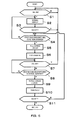
- Fig. 5 is a flowchart showing an operating state of the vehicle information display apparatus according to this embodiment; and
- Fig. 6 to Fig. 16 are front views of display examples of the vehicle information display apparatus according to this embodiment.
- the vehicle information display apparatus includes a meter device (a pointer-type display device) 1 employed as first display means, a multi-display 2 employed as second display means, a transmissive reflecting member 3 arranged between the meter device 1 and the multi-display 2, and a mirror member 4 for reflecting a transmitted and reflected image (described later) formed through the transmissive reflecting member 3 to the direction of a line of sight of a user P.
- a meter device a pointer-type display device
- a multi-display 2 employed as second display means
- a transmissive reflecting member 3 arranged between the meter device 1 and the multi-display 2
- a mirror member 4 for reflecting a transmitted and reflected image (described later) formed through the transmissive reflecting member 3 to the direction of a line of sight of a user P.
- Reference numeral 3a designates a transparent protecting cover.
- the meter device 1 is, for example, composed of a pointer-type display device including a speed meter (first meter device) SP and a tachometer (second meter device) TA arranged on the right side and the left side as shown in Fig.
- first display means is not limited to the pointer-type meter, and a digital display element may be
- the meter device 1 is configured so as to be capable of switching the part of the first display image 16 (the first and second light-emitting display images 15, 16) between the displayed state and the hidden state.
- the multi-display 2 is composed of a display element (image display device) 21 formed, for example, of TFT (thin film transistor) type liquid crystal panel, and a backlight device 23 including light-emitting elements 22 composed, for example, of light-emitting diodes for illuminating the display element 21 from behind.
- the display operation is controlled by the control means, described later, so that the contents or the image information different in type (displayed later) are displayed as second predetermined information in a multiplex manner or a interchangeable manner, and a second display image 24 (see drawings from Fig. 6 on) as the light-emitting display image of the image information is formed by illuminating the backlight device 23.
- the multi-display 2 is adapted to be capable of enlarging or reducing a display range 25 (surface area required for displaying the information) of the second display image 24 via the control means.
- the display element used for the second display means can be selected as desired, and may be a self-emitting element composed of, for example, an organic/inorganic EL (electroluminescence) display. In this case, the backlight device 23 is not necessary.
- the transmissive reflecting member 3 is composed of a half mirror formed by adhering a reflecting film such as a metallic thin film on a light-transmissive synthetic resin plate by means of deposition or the like or a synthetic resin plate of a dark color, and allows the first display image 17 formed by the meter device 1 to be transmitted toward the mirror member 4 and reflects the second display image 24 of the multi-display 2 toward the mirror member 4, thereby combining the first display image 17 and the second display image 24. Therefore, when the meter device 1 and the multi display 2 are viewed on the basis of the transmissive reflecting member 3, the meter device 1 and the multi-display 2 are arranged so that the display surfaces thereof oppose to each other with the intermediary of the transmissive reflecting member 3.
- the meter device 1 and the multi-display 2 are arranged in such a manner that the second display image 24 is displayed so as not to be superimposed on the first light-emitting display image 15 but to be superimposed on the second light-emitting display image 16 when being displayed in a maximum size in the display range 5.
- the mirror member 4 is composed of a concave surface mirror member formed by adhering a reflecting film formed of metallic thin film, for example, on a light-transmissive synthetic resin material or a glass material by means of deposition or the like, and displays the first and second display images 17, 24 remotely in the predetermined display area 5 (see the drawings from Fig. 6 on) by reflecting the first and second display images 17, 24 combined through the transmissive reflecting member 3 toward the user P.
- the vehicle information display apparatus here includes interface terminals 101a to 101j... for entering/outputting various information, described later, an operating switch SW which can be operated manually by the user P, interface means 102, a microcomputer 103 to be connected to the interface means 102, program storage means 104 and storage means 105 for storing required data connected respectively to the microcomputer 103, display drive means 106, backlight drive means 107, meter drive means 108, and meter light-source drive means 109 connected respectively to the output side of the microcomputer 103, and the display element 21, the backlight device 23 (which constitute the multi-display 2), and the speed meter SP and the tachometer TA (which constitute the meter device 1) connected respectively to the output sides of the display drive means 106, the backlight drive means 108, the meter drive means 107 and the meter light-source drive means 109 and, in this embodiment, the microcomputer 103, the program storage means 104,
- the microcomputer 103 processes supplied information (signal) received via the interface terminals 101a to 101j..., the switch SW, the ignition switch IGN, and the interface means 102 and, on the basis of the processing result, operates the display element 21, the back light device 23, the speed meter SP, and the tachometer TA respectively via the display drive means 106, the backlight drive means 107, the meter drive means 108, and the meter light-source drive means 109.
- a supplied information processing program implemented by the microcomputer 103 and a display processing program for operating the vehicle information display apparatus including the meter device 1 and the multi-display 2 on the basis of the result of processing thereof are stored in the program storage means 104, while image information to be displayed on the multi-display 2 is stored in the storage means 105 as an image data.
- the processing programs or the image data may be stored in storage means provided in the microcomputer 103.
- the supplied information supplied to the microcomputer 103 through the interface terminals 101a to 101j... is as follows in this embodiment.
- the interface terminal 101a is a terminal for entering the imaging information of a camera (not shown) mounted to a vehicle body for acquiring image information of the rear side of the vehicle body
- the interface terminal 101b is a terminal for entering navigation information acquired though a navigation (GPS) receiving device
- the interface terminal 101c is a terminal for entering the imaging information of a night-vision camera (not shown) mounted to the vehicle body for acquiring the night-image information in front of the vehicle body during night time
- the interface terminal 101d is a terminal for entering traffic information transmitted from road information observation device
- the interface terminal 101e is a terminal for entering audio information from a vehicle-mounted audio
- the interface terminal 101f is a terminal for entering shift information from a shift position sensor of a transmission device
- the interface terminal 101g is a terminal for entering vehicle speed information from a vehicle speed sensor for detecting the vehicle speed
- the interface terminal 101h is a sensor
- the operating switch SW in this embodiment is a switch for changing over the display type, the contents, and the setting of the multi-display 2, and resetting the display value.
- the ignition switch IGN is a switch for starting the engine and turning the power of the various electrical components (including the vehicle information display apparatus) ON and OFF by the operation of the user P.
- the switching signals on the basis of the operation of these switches are supplied to the microcomputer 103 as switching information via the interface means 102.
- the imaging information supplied to the microcomputer 103 through the interface terminal 101a is processed through a display program stored in the program storage means 104 and, on the basis of the processed result, is displayed on the display element 21 through the display drive means 106 as a second display image 240a (see Fig. 12).
- the navigation information supplied to the microcomputer 103 through the interface terminal 101b is processed in the same manner, and is displayed on the display element 21 through the display drive means 106 as the second display image 24b, 240b (see Fig. 7 and Fig. 13).
- the imaging information of the night-view camera supplied to the microcomputer 103 through the interface terminal 101c is processed in the same manner, and is displayed on the display element 21 through the display drive means 106 as a second display image 240c (see Fig. 8).
- the traffic information supplied to the microcomputer 103 through the interface terminal 101d is processed in the same manner, and is displayed on the display element 21 through the display drive means 106 as second display images 24d and 240d (see Fig. 10 and Fig. 15).
- the audio information supplied to the microcomputer 103 through the interface terminal 101e is processed in the same manner, and is displayed on the display element 21 through the display drive means 106 as second display images 24e, 240e (see Fig. 11 and Fig. 16).
- the shift information supplied to the microcomputer 103 through the interface terminal 101f is processed in the same manner, and is displayed on the display element 21 through the display drive means 106 as a second display image 24f (see Fig. 6, Fig. 7, Fig. 9, Fig. 10 and Fig. 11).
- the vehicle speed information supplied to the microcomputer 103 through the interface terminal 101g is processed through the meter drive program stored in the program storage means 104 and, on the basis of the processed result, the pointer 11 is activated through the meter drive means 108, whereby the speed information is displayed for the user P as the first display image 17 (speed meter SP) (Fig. 6 to Fig. 16).
- the microcomputer 103 also performs the computation process of the travel distance thereof on the basis of the vehicle speed information.
- the processed result is displayed on the display element 21 through the display drive means 106 as a second display image 24g (see Fig. 6, Fig. 7, Fig. 9, Fig. 10, and Fig. 11).
- the number of revolution information supplied to the microcomputer 103 through the interface terminal 101h is processed in the same manner, an the pointer 11 is operated through the meter drive means 108, whereby the number of engine revolution information is displayed as the first display image 17 (tachometer TA) to the user P (see Fig. 6, Fig. 7, Fig. 9, Fig. 10 and Fig. 11).
- the fuel information supplied to the microcomputer 103 through the interface terminal 101i is processed through the display program and, on the basis of the processed result, is displayed on the display element 21 through the display drive means 106 as a second display image 24i (see Fig. 6, Fig. 7, Fig. 9, Fig. 10, and Fig. 11).
- the detected information supplied to the microcomputer 103 through the interface terminals 101j..., for example, the warning information relating to deficiency of the vehicle-mounted battery, is detected it is processed in the same manner as described above, and it is displayed on the display element 21 through the display drive means 106 as second display images 24j, 240j (see Fig. 9 and Fig 14).
- the type of the second display image 24 to be displayed on the multi-display 2 is switched by operating the operating switch SW.
- Fig. 5 the display operation in a case in which the vehicle information display apparatus according to this embodiment is mounted on the automotive vehicle will be described.
- the microcomputer 103 determines whether or not the ignition switch IGN is changed from OFF to ON (the position of the terminal may either be the engine-start position or the accessory position) on the basis of operating information (switching information) of the ignition switch IGN.
- the procedure goes to Step S2, and causes the vehicle information display apparatus (the meter device 1 and the multi-display 2) to provide a normal display.
- the normal display in this embodiment is as shown in Fig.
- the meter device 1 displays the first and second light-emitting display images 15, 16 (SP, TA) in the display area 5 at a distance on the left and right as the first display image 17, and the multi-display 2 displays the second display image 24i as the fuel information, the second display image 24g as the travel distance information (odd, trip information), and the second display image 24f as the shift information between the first and second light-emitting display images 15, 16.
- SP, TA the first and second light-emitting display images 15, 16
- the multi-display 2 displays the second display image 24i as the fuel information, the second display image 24g as the travel distance information (odd, trip information), and the second display image 24f as the shift information between the first and second light-emitting display images 15, 16.
- a chain line represents an outer dimension of the multi-display 2
- a broken line represents a display range 25 of the light-emitting image formed by the multi-display 2 (the non-light-emitting area is excluded)
- Step S2 all the first and second light-emitting display images 15, 16 (SP, TA) are in the displayed state, and a screen on the side of the multi-display 2 which is overlapped with the second light-emitting display image 16 as a part of the second display image 17 is partly hidden (non-light-emitting state) on the left side thereof.
- the side of the meter device 1 in which the display ranges 18, 19 are entirely displayed with light emission is converted into a detail display (enlarged) mode
- the side of the multi-display 2 in which a part of the display range 25 is displayed with light emission is converted into a simple display (reduced) mode.
- Step S3 whether or not the ignition switch IGN has been switched from ON to OFF is determined, and when it is determined not to have been switched to OFF (ON state is maintained) (N), the procedure goes to the next Step S4, where whether or not the first changing/switching condition is satisfied is determined.
- the first changing/switching condition here is the switching condition to switch the meter device 1 side to the simple display mode (a mode in which the second light-emitting display image 16 as a part of the first display image 17 is hidden and only the first light-emitting display image 15 is displayed) and the multi-display 2 side to the detailed display mode (a mode in which the second display image 24 is displayed in detail in an enlarged screen, that is, in a full screen) from the normal display shown in Fig. 6 (the meter device 1 side is in the detailed display mode, and the multi-display 2 side is the simple display mode).
- the simple display mode a mode in which the second light-emitting display image 16 as a part of the first display image 17 is hidden and only the first light-emitting display image 15 is displayed
- the multi-display 2 side to the detailed display mode (a mode in which the second display image 24 is displayed in detail in an enlarged screen, that is, in a full screen) from the normal display shown in Fig. 6 (the meter device 1
- the microcomputer 103 determines that the first changing/switching condition in Step S4 is satisfied (Y), and then in Step S5, enlarges the screen size on the multi-display 2 side into the detailed display (full screen display) mode, displays the imaging information acquired through the interface terminal 101a on the full screen in detail (see Fig. 12), and then performs the first changing/switching process to extinguish, that is, hide the second light-emitting display image (TA) on the meter device 1 side to achieve the simple display in Step S6.
- Step S6 As a processing procedure, the process in Step S6 is performed after the process in Step S5. However, the process in Step S5 (to switch into the full screen display and display the imaging information) and the process in Step S6 (to extinguish TA) are actually recognized as the simultaneous process.
- the first condition is not satisfied (N) as the result of determination in Step S4, the normal display in Step S2 is maintained.
- Step S7 the same determination as in Step S3 is performed, and when the result of determination is OFF (Y), the procedure goes back to Step S1, and when it is ON (that is, the ON state is maintained) (N), the procedure goes to Step S8, where whether or not the second changing/switching condition is satisfied is determined.
- the second changing/switching condition here means a condition for changing the display mode from Step S6 on (the simple display mode on the meter device 1 side, and the detailed display mode on the multi-display 2 side) to the normal display as in Step S2 (the detailed display mode on the meter device 1 side, and the simple display mode on the multi-display 2 side).
- the microcomputer 103 determines that the second changing/switching condition in Step S8 is satisfied (Y) and, in Step S9, reduces the screen size on the multi-display 2 side into the simple display (partial screen display) mode, and displays the same display as in Step S2 instead of the imaging information acquired through the interface terminal 101a (see Fig. 6), and then in Step S10, performs a second changing/switching process for turning the second light-emitting display image (TA) on the meter device 1 side ON, that is, switching the same into the detailed display mode as the displayed state.
- Step S8 the second changing/switching condition in Step S8 is satisfied
- Step S9 reduces the screen size on the multi-display 2 side into the simple display (partial screen display) mode, and displays the same display as in Step S2 instead of the imaging information acquired through the interface terminal 101a (see Fig. 6)
- Step S10 performs a second changing/switching process for turning the second light-emitting display image (TA) on the
- Step S109 is performed after the process in Step S9.
- the process in Step S9 to switch into the partial screen and display the information as in Step S2
- the process in Step S10 to turn TA ON
- the second changing/switching condition is not satisfied as the result of determination in Step S8 (N)
- the state after the Step S6 is maintained.
- the same display as in the case of the Step S2 is performed upon satisfaction of the second changing/switching condition in Step S8.
- the contents of display in the multi-display 2 are changed by operating the operating switch SW or the like (for example, when the display state is changed from the one shown in Fig. 6 to the states shown in Fig. 7, Fig. 9, Fig. 10, and Fig. 11), the state after change can be displayed.
- Step S11 determinations as in Steps S3 and S7 are performed, and when the result of determination here is "OFF" (Y), the procedure goes back to Step S1, and when it is "ON” (N), the procedure goes back to Step S4, where whether or not the first changing/switching condition is satisfied is determined again.
- the simple display mode including only the required minimum last information as shown in Fig. 7 (see the second display image 24b in the drawing) and the detailed display mode showing the position of the own-vehicle in a map as shown in Fig. 13 (see the second display image 240b in the drawing) are provided as the display modes (mode) of the navigation information for entering through the interface terminal 101b, and the simple display mode showing only a warning mark as shown in Fig. 9 (see the second display image 24j in the drawing) and the detailed display mode for displaying an article of the user's manual including the meaning of the mark and the countermeasure therefor in addition to the warning mark as text information as shown in Fig.
- the simple display mode including only a reminder mark as shown in Fig. 10 (see the second display image 24d in the drawing) and the detailed display mode displaying the pickup image of the actual road condition as shown in Fig. 15 (see the second display image 240d in the drawing) are provided as the display mode of the traffic information to be supplied through the interface terminal 101d, and the simple display mode showing only the CD track number and the playing duration as shown in Fig. 11 (see the second display image 24e in the drawing), and the detailed display mode including the title of a song and the name of an artist and the like as shown in Fig. 16 (see the second display image 240e in the drawing) are provided as the display mode of the audio information to be supplied through the interface terminal 101e.
- these two information display modes are adapted to be capable of being selected or changed freely by the user P according to the preference of the user P, for example, by changing the set data stored in the control means 110 through the operating switch SW.
- the information set to the detailed display mode in the setting before change is changed into the simple display mode in the setting after change, and the information set to the simple display mode in the setting before the change is changed to the detailed display mode in the setting after the change.
- the first and second changing/switching conditions are changed according to the change of the setting of the display mode as described above, that is, the conditions for switching the display mode of the first display image 17 are also changed in association with the change of the display mode of the second display image 24.
- the warning information is supplied through the interface terminal 101j when the normal display mode (for example, see Fig. 6) is active, if the user P has set the display mode of the warning information to the simple display mode, the first changing/switching process is failed.
- the vehicle information display apparatus including the meter device (first display means) which displays the first display image 17 and the multi-display (second display means) 2 for displaying the second display image 24, and the control means 110 for controlling the operating state of the meter device 1 and the multi-display 2 and displaying the first and second display images 17, 24 in the predetermined display area 5
- the meter device 1 is adapted to be capable of switching the displayed/hidden state of a part of the first display image 17 (the second light-emitting display image 16)
- the multi-display 2 is adapted to be capable of enlarging and reducing the display range of the second display image 24, and the control means 110 switches a part of the first display image 17 (the second light-emitting display image 16) into the hidden state (switches into the simple display mode) in association with the enlargement of the display range 25 of the second display image 24 (change into the detailed display mode) and switches a part of the first display image 17 (the second light-emitting display image 16) into
- Selection of the display mode between the first and second display images 17, 24 is arbitrary, and may be determined according to the attributes, the contents, and the types of the displayed information and the preference of the user P, and may also be determined according to the priority, the importance, the urgency, and the like of the displayed information.
- the change of the display range 25 of the multi-display 2 and the switching of the partial display of the meter device 1 between the displayed state and the hidden state in association with the change can be achieved according to the attribute (characteristic,
- This embodiment is configured to determine whether or not the display range changing conditions for enlarging and reducing the display range 25 according to the predetermined supplied information are satisfied through the control means 110 (Step S4, Step S8) and, when the display range changing conditions are satisfied, display the second display image 24 in the enlarged or reduced display range 25. In this configuration, reliable switching operation can be ensured.
- the display range changing conditions can be changed by the user, the display can be selected according to the preference of the user P, and the usability can be improved.
- the first display means is the meter device (the pointer-type display device) and the second display means is composed of the image display device in which the second display means displays a plurality of different contents or types of information in the multiplex manner or the interchangeable manner as the second display image 24, the easily viewable display including an analogue display image and the image information in combination can be achieved.
- the meter device 1 and the multi-display 2 are arranged so as to oppose to each other with the intermediary of the transmissive reflecting member 3 that combines the respective display images by transmitting the display image on one of the meter device 1 and the multi-display 2 and reflecting the display image on the other one of them, it is effective for setting the respective display ranges 25, 18, 19 of the respective display images formed by using the two display means so as to be overlapped with respect to each other.
- the display images of the first and second display images 17, 24 can be displayed remotely in an enlarged scale, so that there are merits such that the visibility can be improved, and the size of the display means can be reduced.
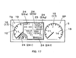
- Fig. 17 shows a modification of the vehicle information display apparatus according to the invention.
- the second display image 24 is displayed in the detailed display mode (enlarged display mode)
- a part (substantially half) of the second light-emitting display image 16 which constitutes the first display image 17 is brought into a hidden state.
- the same effects as the above-described embodiment are expected.
- the display means includes two display means, that is, the first and second display means (the meter device and the multi-display 2) has been described as an example.
- the number of the display means must simply be at least two, and more than two display means can also be employed.
- the display range 25 may be divided into a plurality of ranges, and in this case, the enlargement or reduction must simply be performed so that the display surface area of the entire second display image 24 is changed.
- the display range 25 is not divided into sections and set to a single range, the enlargement and reduction must simply be performed so that at least a part of the display surface area thereof is changed.
- the invention is preferable for a vehicle information display apparatus and a method of displaying vehicle information which are applied to a moving body like an automotive vehicle as a primary example.
Landscapes
- Engineering & Computer Science (AREA)
- Chemical & Material Sciences (AREA)
- Combustion & Propulsion (AREA)
- Transportation (AREA)
- Mechanical Engineering (AREA)
- Instrument Panels (AREA)
- Controls And Circuits For Display Device (AREA)
- Indicating Measured Values (AREA)
Abstract
Description
- The present invention relates to a vehicle information display apparatus mounted, for example, to an instrument panel of an automotive vehicle for providing various information (for example, measured information such as the vehicle speed, the number of engine revolution, the remaining amount in a tank, the water temperature, the travel distance, and the time of the day, navigation information, and camera imaging information) to an observer visually and a method of displaying vehicle information and, more specifically, to a vehicle information display apparatus for displaying information display images formed by a plurality of display means within a common display area such as a panel member or a screen, and a method of displaying vehicle information.
- A vehicle information display apparatus of this type disclosed in
Patent Document 1 shown below is known. In the vehicle information display apparatus disclosed inPatent Document 1, a display area of the display apparatus is divided into left and right areas; a fixed display area and an interchangeable display area, so that a pointer-type display (vehicle speed display and remaining fuel amount display by a pointer-type analogue meter) is carried out constantly in the fixed display section, and a pointer-type display (display of the number of engine revolution and display of a water temperature gauge by a pointer-type analogue meter) and navigation information display (display on a liquid crystal display) are switched in the interchangeable display section. According to the vehicle information display apparatus, necessary information can be displayed in the interchangeable display area while displaying information which is important for traveling of the vehicle constantly displayed in the fixed display area, as well as various and a large amount of information can be displayed in a multiplex manner or in an interchangeable manner by utilizing the display on the liquid crystal display.
[Patent Document 1]JP-A-2002-046505 - However, the vehicle information display apparatus disclosed in the above-described
Patent Document 1 has following problems. Although a multiplex or interchangeable display is possible by the liquid crystal display in the interchangeable display area, the display range (surface area or a display size) is not changed and is always constant, and hence when displaying fine images such as navigation information, monitor (camera) information, and a large amount of character information in a relatively narrow display range, display of image itself may become difficult, or even though it can be displayed, the display may be difficult to recognize. On the other hand, when displaying a simple image such as only a warning mark or a small amount of character information in a relatively large display range, the image occupies a surface area of the entire display more than necessary, and hence information of other display devices (such as the pointer-type analogue meter) cannot be displayed. Therefore, there is still a room for improvement. - Therefore, in order to solve the above-described problems, the invention provides a vehicle information display apparatus and a method of displaying vehicle information in which an optimal display can be achieved according to attributes (characteristic, property), contents, and types of displayed information and preference of a user, and the like while constraining upsizing of an entire display area.
- In order to achieve the above-described object, the invention provides a vehicle information display apparatus including first display means for displaying first predetermined information as a first display image, second display means for displaying second predetermined information as a second display image and control means for controlling operating states of the first and second display means, and displaying the first and second display images in a predetermined display area, characterized in that the first display means is adapted to be capable of switching between a displayed state and a hidden state of a part of the first display image, the second display means is adapted to be capable of enlarging and reducing the display range of the second display image, and the control means switches the part of the first display image into the hidden state in association with enlargement of the display range of the second display image and switches the part of the first display image into the displayed state in association with reduction of the display range of the second display image.
- In order to achieve the above-described object, the invention provides a method of displaying vehicle information for displaying a first display image which provides a first predetermined information and whose display state is partly switched between a displayed state and a hidden state, and a second display image which provides a second predetermined information and whose display range is enlarged and reduced in a predetermined display area, characterized in that a part of the first display image is switched to the hidden state in association with enlargement of the display range of the second display image, and the part of the first display image is switched to the displayed state in association with reduction of the display range of the second display image.
- The invention is characterized in that the control means determines whether or not the changing/switching conditions for switching the display of the first display image in association with the change of the display range of the second display image is satisfied according to the predetermined supplied information and, when the changing/switching conditions are satisfied, changes the display range of the second display image and switches the display of the first display image.
- The invention is also characterized in that the changing/switching conditions can be changed by the user.
- The invention is also characterized in that the first display means is a pointer-type display device, and the second display means is an image display device for displaying a plurality of different contents or types of the second predetermined information as the second display image in a multiplex or interchangeable manner.
- The invention is also characterized in that the first display means and the second display means are arranged so as to oppose to each other with the intermediary of a transmissive reflecting member that combines the respective display images by transmitting the display image on one of the first display means and the second display means and reflecting the display image on the other one of them.
- The invention is also characterized in that a concave surface mirror member that reflects the first and second display images combined through the transmissive reflecting member toward the user is further provided.
- According to the invention, a vehicle information display apparatus and a method of displaying vehicle information in which an initial object can be achieved and an optimal display can be obtained according to the attributes (characteristic, property), the contents, and the types of the displayed information and preference of the user, and the like while constraining upsizing of an entire display area can be provided.
-
- [Fig. 1] Fig. 1 is a drawing showing a schematic configuration of a vehicle information display apparatus according to a first embodiment of the invention.
- [Fig. 2] Fig..2 is a front view of a meter device according to the same embodiment.
- [Fig. 3] Fig. 3 is a front view of a multi-display according to the same embodiment.
- [Fig. 4] Fig. 4 is a block diagram showing a system configuration of the vehicle information display apparatus according to the same embodiment.
- [Fig. 5] Fig. 5 is a flowchart showing an operating state of the vehicle information display apparatus according to the same embodiment.
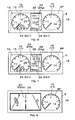
- [Fig. 6] Fig. 6 is a front view of a display example of the vehicle information display apparatus according to the same embodiment.
- [Fig. 7] Fig. 7 is a front view of another display example of the vehicle information display apparatus according to the same embodiment.
- [Fig. 8] Fig. 8 is a front view of another display example of the vehicle information display apparatus according to the same embodiment.
- [Fig. 9] Fig. 9 is a front view of another display example of the vehicle information display apparatus according to the same embodiment.
- [Fig. 10] Fig. 10 is a front view of another display example of the vehicle information display apparatus according to the same embodiment.
- [Fig. 11] Fig. 11 is a front view of another display example of the vehicle information display apparatus according to the same embodiment.
- [Fig. 12] Fig. 12 is a front view of another display example of the vehicle information display apparatus according to the same embodiment.
- [Fig. 13] Fig. 13 is a front view of another display example of the vehicle information display apparatus according to the same embodiment.
- [Fig. 14] Fig. 14 is a front view of another display example of the vehicle information display apparatus according to the same embodiment.
- [Fig. 15] Fig. 15 is a front view of another display example of the vehicle information display apparatus according to the same embodiment.
- [Fig. 16] Fig. 16 is a front view of another display example of the vehicle information display apparatus according to the same embodiment.
- [Fig. 17] Fig. 17 is a front view of a modification of the vehicle information display apparatus according to the invention showing a display example thereof.
- Referring now to the drawings, an embodiment of a case in which a vehicle information display apparatus according to the invention is applied to a vehicle-mounted instrument apparatus will be described as an example.
Fig. 1 to Fig. 16 illustrate a first embodiment of the invention. Fig. 1 is a drawing showing a schematic configuration of the vehicle information display apparatus according to this embodiment; Fig. 2 is a front view of a meter device according to this embodiment; Fig. 3 is a front view of a multi-display according to this embodiment; Fig. 4 is a block diagram showing a system configuration of the vehicle information display apparatus according to this embodiment; Fig. 5 is a flowchart showing an operating state of the vehicle information display apparatus according to this embodiment; and Fig. 6 to Fig. 16 are front views of display examples of the vehicle information display apparatus according to this embodiment. - In Fig. 1, the vehicle information display apparatus includes a meter device (a pointer-type display device) 1 employed as first display means, a multi-display 2 employed as second display means, a transmissive reflecting
member 3 arranged between themeter device 1 and the multi-display 2, and amirror member 4 for reflecting a transmitted and reflected image (described later) formed through the transmissive reflectingmember 3 to the direction of a line of sight of a userP. Reference numeral 3a designates a transparent protecting cover. - The
meter device 1 is, for example, composed of a pointer-type display device including a speed meter (first meter device) SP and a tachometer (second meter device) TA arranged on the right side and the left side as shown in Fig. 2, each including apointer 11, a scaledplate 13 having anindex part 12 such as graduation or characters which is to be pointed by thepointer 11, and ameter light source 14 composed of a light-emitting diode for causing thepointer 11 and the scaledplate 13 to emit light and forms twofirst display images 17 including a light-emitting display image 15 of the speed meter SP and a light-emitting display image 16 of the tachometer TA as first predetermined information (measured information relating to the vehicle speed, and measured information relating to the number of engine revolution) by controlling the operating state of thepointer 11 by control means, described later, according to the measured amount and illuminating themeter light source 14, so that the first and second light-emittingdisplay images meter light source 14 independently for the speed meter SP and the tachometer TA by the control means. The first display means is not limited to the pointer-type meter, and a digital display element may be employed, and the contents of display thereof may be those other than the measured information. - Accordingly, the
meter device 1 is configured so as to be capable of switching the part of the first display image 16 (the first and second light-emitting display images 15, 16) between the displayed state and the hidden state. - As shown in Fig. 3, the multi-display 2 is composed of a display element (image display device) 21 formed, for example, of TFT (thin film transistor) type liquid crystal panel, and a
backlight device 23 including light-emittingelements 22 composed, for example, of light-emitting diodes for illuminating thedisplay element 21 from behind. The display operation is controlled by the control means, described later, so that the contents or the image information different in type (displayed later) are displayed as second predetermined information in a multiplex manner or a interchangeable manner, and a second display image 24 (see drawings from Fig. 6 on) as the light-emitting display image of the image information is formed by illuminating thebacklight device 23. The multi-display 2 is adapted to be capable of enlarging or reducing a display range 25 (surface area required for displaying the information) of thesecond display image 24 via the control means. The display element used for the second display means can be selected as desired, and may be a self-emitting element composed of, for example, an organic/inorganic EL (electroluminescence) display. In this case, thebacklight device 23 is not necessary. - The transmissive reflecting
member 3 is composed of a half mirror formed by adhering a reflecting film such as a metallic thin film on a light-transmissive synthetic resin plate by means of deposition or the like or a synthetic resin plate of a dark color, and allows thefirst display image 17 formed by themeter device 1 to be transmitted toward themirror member 4 and reflects thesecond display image 24 of the multi-display 2 toward themirror member 4, thereby combining thefirst display image 17 and thesecond display image 24. Therefore, when themeter device 1 and themulti display 2 are viewed on the basis of the transmissive reflectingmember 3, themeter device 1 and the multi-display 2 are arranged so that the display surfaces thereof oppose to each other with the intermediary of the transmissive reflectingmember 3. In this embodiment, themeter device 1 and the multi-display 2 are arranged in such a manner that thesecond display image 24 is displayed so as not to be superimposed on the first light-emitting display image 15 but to be superimposed on the second light-emittingdisplay image 16 when being displayed in a maximum size in thedisplay range 5. - The
mirror member 4 is composed of a concave surface mirror member formed by adhering a reflecting film formed of metallic thin film, for example, on a light-transmissive synthetic resin material or a glass material by means of deposition or the like, and displays the first andsecond display images second display images member 3 toward the user P. - Referring now to Fig. 4, the system configuration of the vehicle information display apparatus according to this embodiment will be described. The vehicle information display apparatus here includes
interface terminals 101a to 101j... for entering/outputting various information, described later, an operating switch SW which can be operated manually by the user P, interface means 102, amicrocomputer 103 to be connected to the interface means 102, program storage means 104 and storage means 105 for storing required data connected respectively to themicrocomputer 103, display drive means 106, backlight drive means 107, meter drive means 108, and meter light-source drive means 109 connected respectively to the output side of themicrocomputer 103, and thedisplay element 21, the backlight device 23 (which constitute the multi-display 2), and the speed meter SP and the tachometer TA (which constitute the meter device 1) connected respectively to the output sides of the display drive means 106, the backlight drive means 108, the meter drive means 107 and the meter light-source drive means 109 and, in this embodiment, themicrocomputer 103, the program storage means 104, the storage means 105, the display drive means 106, the backlight drive means 107, the meter drive means 108, and the meter light-source drive means 109 constitute control means 110. An ignition switch IGN is connected to themicrocomputer 103 via the interface means 102. - The
microcomputer 103 processes supplied information (signal) received via theinterface terminals 101a to 101j..., the switch SW, the ignition switch IGN, and the interface means 102 and, on the basis of the processing result, operates thedisplay element 21, theback light device 23, the speed meter SP, and the tachometer TA respectively via the display drive means 106, the backlight drive means 107, the meter drive means 108, and the meter light-source drive means 109. - A supplied information processing program implemented by the
microcomputer 103 and a display processing program for operating the vehicle information display apparatus including themeter device 1 and the multi-display 2 on the basis of the result of processing thereof are stored in the program storage means 104, while image information to be displayed on the multi-display 2 is stored in the storage means 105 as an image data. The processing programs or the image data may be stored in storage means provided in themicrocomputer 103. In the same manner, it is also possible to integrate functions of the display drive means 106, the backlight drive means 107, the meter drive means 108, and the meter light-source drive means 109 in themicrocomputer 103. - The supplied information supplied to the
microcomputer 103 through theinterface terminals 101a to 101j... is as follows in this embodiment. The interface terminal 101a is a terminal for entering the imaging information of a camera (not shown) mounted to a vehicle body for acquiring image information of the rear side of the vehicle body, the interface terminal 101b is a terminal for entering navigation information acquired though a navigation (GPS) receiving device, the interface terminal 101c is a terminal for entering the imaging information of a night-vision camera (not shown) mounted to the vehicle body for acquiring the night-image information in front of the vehicle body during night time, the interface terminal 101d is a terminal for entering traffic information transmitted from road information observation device, the interface terminal 101e is a terminal for entering audio information from a vehicle-mounted audio, the interface terminal 101f is a terminal for entering shift information from a shift position sensor of a transmission device, the interface terminal 101g is a terminal for entering vehicle speed information from a vehicle speed sensor for detecting the vehicle speed, the interface terminal 101h is a sensor for entering information on the number of revolution from a revolution sensor for detecting the number of engine revolution, the interface terminal 101i is a terminal for entering fuel information from a fuel sensor for detecting the amount of fuel in the fuel tank, the interface terminals 101j ... are terminals for entering the detected information from various sensors (state detecting means) for detecting various states (abnormal states) of the vehicle body. - The operating switch SW in this embodiment is a switch for changing over the display type, the contents, and the setting of the
multi-display 2, and resetting the display value. The ignition switch IGN is a switch for starting the engine and turning the power of the various electrical components (including the vehicle information display apparatus) ON and OFF by the operation of the user P. The switching signals on the basis of the operation of these switches are supplied to themicrocomputer 103 as switching information via the interface means 102. - Subsequently, the processing by the control means 110 relating to the input information received through the respective interface means 101a to 101j will be described.
The imaging information supplied to themicrocomputer 103 through theinterface terminal 101a is processed through a display program stored in the program storage means 104 and, on the basis of the processed result, is displayed on thedisplay element 21 through the display drive means 106 as asecond display image 240a (see Fig. 12). - Subsequently, the navigation information supplied to the
microcomputer 103 through theinterface terminal 101b is processed in the same manner, and is displayed on thedisplay element 21 through the display drive means 106 as thesecond display image - Subsequently, the imaging information of the night-view camera supplied to the
microcomputer 103 through the interface terminal 101c is processed in the same manner, and is displayed on thedisplay element 21 through the display drive means 106 as asecond display image 240c (see Fig. 8). - Subsequently, the traffic information supplied to the
microcomputer 103 through theinterface terminal 101d is processed in the same manner, and is displayed on thedisplay element 21 through the display drive means 106 assecond display images - Subsequently, the audio information supplied to the
microcomputer 103 through theinterface terminal 101e is processed in the same manner, and is displayed on thedisplay element 21 through the display drive means 106 assecond display images 24e, 240e (see Fig. 11 and Fig. 16). - Subsequently, the shift information supplied to the
microcomputer 103 through the interface terminal 101f is processed in the same manner, and is displayed on thedisplay element 21 through the display drive means 106 as a second display image 24f (see Fig. 6, Fig. 7, Fig. 9, Fig. 10 and Fig. 11). - Subsequently, the vehicle speed information supplied to the
microcomputer 103 through theinterface terminal 101g is processed through the meter drive program stored in the program storage means 104 and, on the basis of the processed result, thepointer 11 is activated through the meter drive means 108, whereby the speed information is displayed for the user P as the first display image 17 (speed meter SP) (Fig. 6 to Fig. 16). Themicrocomputer 103 also performs the computation process of the travel distance thereof on the basis of the vehicle speed information. The processed result is displayed on thedisplay element 21 through the display drive means 106 as asecond display image 24g (see Fig. 6, Fig. 7, Fig. 9, Fig. 10, and Fig. 11). - Subsequently the number of revolution information supplied to the
microcomputer 103 through theinterface terminal 101h is processed in the same manner, an thepointer 11 is operated through the meter drive means 108, whereby the number of engine revolution information is displayed as the first display image 17 (tachometer TA) to the user P (see Fig. 6, Fig. 7, Fig. 9, Fig. 10 and Fig. 11). - Subsequently, the fuel information supplied to the
microcomputer 103 through the interface terminal 101i is processed through the display program and, on the basis of the processed result, is displayed on thedisplay element 21 through the display drive means 106 as a second display image 24i (see Fig. 6, Fig. 7, Fig. 9, Fig. 10, and Fig. 11). - Subsequently, in a case in which the detected information supplied to the
microcomputer 103 through the interface terminals 101j..., for example, the warning information relating to deficiency of the vehicle-mounted battery, is detected, it is processed in the same manner as described above, and it is displayed on thedisplay element 21 through the display drive means 106 assecond display images 24j, 240j (see Fig. 9 and Fig 14). - Then, the type of the
second display image 24 to be displayed on themulti-display 2 is switched by operating the operating switch SW. - Referring now to Fig. 5, the display operation in a case in which the vehicle information display apparatus according to this embodiment is mounted on the automotive vehicle will be described.
- The
microcomputer 103 determines whether or not the ignition switch IGN is changed from OFF to ON (the position of the terminal may either be the engine-start position or the accessory position) on the basis of operating information (switching information) of the ignition switch IGN. When it is determined to have been switched to ON (Y), the procedure goes to Step S2, and causes the vehicle information display apparatus (themeter device 1 and the multi-display 2) to provide a normal display. The normal display in this embodiment is as shown in Fig. 6, and themeter device 1 displays the first and second light-emittingdisplay images 15, 16 (SP, TA) in thedisplay area 5 at a distance on the left and right as thefirst display image 17, and themulti-display 2 displays the second display image 24i as the fuel information, thesecond display image 24g as the travel distance information (odd, trip information), and the second display image 24f as the shift information between the first and second light-emittingdisplay images multi-display 2, and a broken line represents adisplay range 25 of the light-emitting image formed by the multi-display 2 (the non-light-emitting area is excluded), and display ranges 18, 19 of the first and second light-emittingdisplay images 15, 16 (SP, TA). In the normal state in Step S2, all the first and second light-emittingdisplay images 15, 16 (SP, TA) are in the displayed state, and a screen on the side of the multi-display 2 which is overlapped with the second light-emittingdisplay image 16 as a part of thesecond display image 17 is partly hidden (non-light-emitting state) on the left side thereof. Therefore, the side of themeter device 1 in which the display ranges 18, 19 are entirely displayed with light emission is converted into a detail display (enlarged) mode, and the side of the multi-display 2 in which a part of thedisplay range 25 is displayed with light emission is converted into a simple display (reduced) mode. - Subsequently, in Step S3, whether or not the ignition switch IGN has been switched from ON to OFF is determined, and when it is determined not to have been switched to OFF (ON state is maintained) (N), the procedure goes to the next Step S4, where whether or not the first changing/switching condition is satisfied is determined. The first changing/switching condition here is the switching condition to switch the
meter device 1 side to the simple display mode (a mode in which the second light-emittingdisplay image 16 as a part of thefirst display image 17 is hidden and only the first light-emittingdisplay image 15 is displayed) and the multi-display 2 side to the detailed display mode (a mode in which thesecond display image 24 is displayed in detail in an enlarged screen, that is, in a full screen) from the normal display shown in Fig. 6 (themeter device 1 side is in the detailed display mode, and the multi-display 2 side is the simple display mode). - Here, for example, when the shift information which notifies the
microcomputer 103 of the fact that the shift position is switched to "R (reverse)" through the interface terminal 101f is supplied, themicrocomputer 103 determines that the first changing/switching condition in Step S4 is satisfied (Y), and then in Step S5, enlarges the screen size on themulti-display 2 side into the detailed display (full screen display) mode, displays the imaging information acquired through theinterface terminal 101a on the full screen in detail (see Fig. 12), and then performs the first changing/switching process to extinguish, that is, hide the second light-emitting display image (TA) on themeter device 1 side to achieve the simple display in Step S6. As a processing procedure, the process in Step S6 is performed after the process in Step S5. However, the process in Step S5 (to switch into the full screen display and display the imaging information) and the process in Step S6 (to extinguish TA) are actually recognized as the simultaneous process. When the first condition is not satisfied (N) as the result of determination in Step S4, the normal display in Step S2 is maintained. - Although the case to achieve the display as shown in Fig. 12 as the first changing/switching condition has been exemplified and described here, for example, a case in which the display of the imaging information of the night-view camera is selected as shown in Fig. 8 by operation of the operation switch SW by the user P, or a case in which the detailed display of the navigation information as shown in Fig. 13 (see the
second display image 24b in Fig. 7 for an example of the simple display), the detailed display of the warning information as shown in Fig. 14 (see the second display image 24j in Fig. 9 for an example of the simple display), the detailed display of the traffic information as shown in Fig. 15 (see thesecond display image 24d in Fig. 10 for an example of the simple display), and the detailed display of the audio information as shown in Fig. 16 (see the second display image 24e in Fig. 11 as an example of the simple display) is selected according to the customization by the user P are also included. - Subsequently, in Step S7, the same determination as in Step S3 is performed, and when the result of determination is OFF (Y), the procedure goes back to Step S1, and when it is ON (that is, the ON state is maintained) (N), the procedure goes to Step S8, where whether or not the second changing/switching condition is satisfied is determined. The second changing/switching condition here means a condition for changing the display mode from Step S6 on (the simple display mode on the
meter device 1 side, and the detailed display mode on themulti-display 2 side) to the normal display as in Step S2 (the detailed display mode on themeter device 1 side, and the simple display mode on themulti-display 2 side). - For example, when the shift information which notifies the
microcomputer 103 of the fact that the shift position is switched to a mode other than "R (reverse)" through the interface terminal 101f is supplied, themicrocomputer 103 determines that the second changing/switching condition in Step S8 is satisfied (Y) and, in Step S9, reduces the screen size on themulti-display 2 side into the simple display (partial screen display) mode, and displays the same display as in Step S2 instead of the imaging information acquired through theinterface terminal 101a (see Fig. 6), and then in Step S10, performs a second changing/switching process for turning the second light-emitting display image (TA) on themeter device 1 side ON, that is, switching the same into the detailed display mode as the displayed state. As the processing procedure, the process in Step S109 is performed after the process in Step S9. However, the process in Step S9 (to switch into the partial screen and display the information as in Step S2) and the process in Step S10 (to turn TA ON) are actually recognized as the simultaneous processing. When the second changing/switching condition is not satisfied as the result of determination in Step S8 (N), the state after the Step S6 is maintained. - In this embodiment, the same display as in the case of the Step S2 is performed upon satisfaction of the second changing/switching condition in Step S8. However, when the contents of display in the
multi-display 2 are changed by operating the operating switch SW or the like (for example, when the display state is changed from the one shown in Fig. 6 to the states shown in Fig. 7, Fig. 9, Fig. 10, and Fig. 11), the state after change can be displayed. - In the next Step S11, determinations as in Steps S3 and S7 are performed, and when the result of determination here is "OFF" (Y), the procedure goes back to Step S1, and when it is "ON" (N), the procedure goes back to Step S4, where whether or not the first changing/switching condition is satisfied is determined again.
- The setting for customization for the user P will now be described.
In this embodiment, the simple display mode including only the required minimum last information as shown in Fig. 7 (see thesecond display image 24b in the drawing) and the detailed display mode showing the position of the own-vehicle in a map as shown in Fig. 13 (see thesecond display image 240b in the drawing) are provided as the display modes (mode) of the navigation information for entering through theinterface terminal 101b, and the simple display mode showing only a warning mark as shown in Fig. 9 (see the second display image 24j in the drawing) and the detailed display mode for displaying an article of the user's manual including the meaning of the mark and the countermeasure therefor in addition to the warning mark as text information as shown in Fig. 14 (see thesecond display image 240j in the drawing) are provided as the display mode of the warning information to be supplied through the interface terminal 101j. The simple display mode including only a reminder mark as shown in Fig. 10 (see thesecond display image 24d in the drawing) and the detailed display mode displaying the pickup image of the actual road condition as shown in Fig. 15 (see thesecond display image 240d in the drawing) are provided as the display mode of the traffic information to be supplied through theinterface terminal 101d, and the simple display mode showing only the CD track number and the playing duration as shown in Fig. 11 (see the second display image 24e in the drawing), and the detailed display mode including the title of a song and the name of an artist and the like as shown in Fig. 16 (see thesecond display image 240e in the drawing) are provided as the display mode of the audio information to be supplied through theinterface terminal 101e. - Then, these two information display modes (the simple display mode and the detailed display mode) are adapted to be capable of being selected or changed freely by the user P according to the preference of the user P, for example, by changing the set data stored in the control means 110 through the operating switch SW. According to the change of the setting as described above, the information set to the detailed display mode in the setting before change is changed into the simple display mode in the setting after change, and the information set to the simple display mode in the setting before the change is changed to the detailed display mode in the setting after the change. Therefore, the first and second changing/switching conditions are changed according to the change of the setting of the display mode as described above, that is, the conditions for switching the display mode of the
first display image 17 are also changed in association with the change of the display mode of thesecond display image 24. For example, even when the warning information is supplied through the interface terminal 101j when the normal display mode (for example, see Fig. 6) is active, if the user P has set the display mode of the warning information to the simple display mode, the first changing/switching process is failed. - As described above, according to this embodiment, in the vehicle information display apparatus including the meter device (first display means) which displays the first display image 17 and the multi-display (second display means) 2 for displaying the second display image 24, and the control means 110 for controlling the operating state of the meter device 1 and the multi-display 2 and displaying the first and second display images 17, 24 in the predetermined display area 5, the meter device 1 is adapted to be capable of switching the displayed/hidden state of a part of the first display image 17 (the second light-emitting display image 16), the multi-display 2 is adapted to be capable of enlarging and reducing the display range of the second display image 24, and the control means 110 switches a part of the first display image 17 (the second light-emitting display image 16) into the hidden state (switches into the simple display mode) in association with the enlargement of the display range 25 of the second display image 24 (change into the detailed display mode) and switches a part of the first display image 17 (the second light-emitting display image 16) into the displayed state (switches into the detailed display mode) in association with the reduction of the display range of the second display image 24 (change into the simple display mode), so that the change of the display range 25 of the multi-display 2 and the partial switching between the displayed and the hidden state of the meter device 1 can be achieved in association with the change according to the attributes (characteristic, property), the contents, and the types of the displayed information and the preference of the user, and the like, whereby an optimal display is achieved according to the attributes (characteristic, property), the contents, and the types of the displayed information and the preference of the user P, and the like while constraining upsizing of the entire display area 5. Selection of the display mode between the first and
second display images - In this embodiment, in the method of displaying vehicle information for displaying the first display image 17 whose state is switched between the displayed state and the hidden state for a part (the second light-emitting display image 16) thereof, and displaying the second display image 24 for enlarging or reducing the display range 25 in the predetermined display area 5, since a part (the second light-emitting display image) of the first display image 17 is switched to the hidden state (switched to the simple display mode) in association with the enlargement (change to the detailed display mode) of the display range 25 of the second display image 24, and a part (the second light-emitting display image 16) of the first display image 17 is switched to the display state (switched to the detailed display mode) in association with the reduction of the display range 25 of the second display image 24 (change of the simple display mode), the change of the display range 25 of the multi-display 2 and the switching of the partial display of the meter device 1 between the displayed state and the hidden state in association with the change can be achieved according to the attribute (characteristic, property), the contents, and the types of the display information, the preference of the user, and the like, whereby an optimal display can be achieved according to the attributes (characteristic, property), the contents, and the types of the displayed information and the preference of the user, and the like while constraining upsizing of the entire display area 5.
- This embodiment is configured to determine whether or not the display range changing conditions for enlarging and reducing the
display range 25 according to the predetermined supplied information are satisfied through the control means 110 (Step S4, Step S8) and, when the display range changing conditions are satisfied, display thesecond display image 24 in the enlarged or reduceddisplay range 25. In this configuration, reliable switching operation can be ensured. - According to this embodiment, since the display range changing conditions can be changed by the user, the display can be selected according to the preference of the user P, and the usability can be improved.
- According to this embodiment, since the first display means is the meter device (the pointer-type display device) and the second display means is composed of the image display device in which the second display means displays a plurality of different contents or types of information in the multiplex manner or the interchangeable manner as the
second display image 24, the easily viewable display including an analogue display image and the image information in combination can be achieved. - According to this embodiment, since the
meter device 1 and themulti-display 2 are arranged so as to oppose to each other with the intermediary of thetransmissive reflecting member 3 that combines the respective display images by transmitting the display image on one of themeter device 1 and themulti-display 2 and reflecting the display image on the other one of them, it is effective for setting the respective display ranges 25, 18, 19 of the respective display images formed by using the two display means so as to be overlapped with respect to each other. - According to this embodiment, since the concave
surface mirror member 4 that reflects the first andsecond display images transmissive reflecting member 3 toward the user P is further provided, the display images of the first andsecond display images - Fig. 17 shows a modification of the vehicle information display apparatus according to the invention. In this embodiment, when the
second display image 24 is displayed in the detailed display mode (enlarged display mode), a part (substantially half) of the second light-emittingdisplay image 16 which constitutes thefirst display image 17 is brought into a hidden state. In this modification, the same effects as the above-described embodiment are expected. - In the above-described embodiment and modification, the case in which the display means includes two display means, that is, the first and second display means (the meter device and the multi-display 2) has been described as an example. However, the number of the display means must simply be at least two, and more than two display means can also be employed.
- The example in which the
multi-display 2 is employed as the second display means, and the size of thedisplay range 25 of thesecond display image 24 formed thereby is continuously changed (the example in which the size of thesingle display range 25 is changed) has shown above. However, thedisplay range 25 may be divided into a plurality of ranges, and in this case, the enlargement or reduction must simply be performed so that the display surface area of the entiresecond display image 24 is changed. When thedisplay range 25 is not divided into sections and set to a single range, the enlargement and reduction must simply be performed so that at least a part of the display surface area thereof is changed. - The invention is preferable for a vehicle information display apparatus and a method of displaying vehicle information which are applied to a moving body like an automotive vehicle as a primary example.
Claims (7)
- A vehicle information display apparatus comprising: first display means for displaying first predetermined information as a first display image; second display means for displaying second predetermined information as a second display image; and control means for controlling operating states of the first and second display means, and displaying the first and second display images in a predetermined display area,
characterized in that the first display means is adapted to be capable of switching between a displayed state and a hidden state of a part of the first display image,
the second display means is adapted to be capable of enlarging and reducing the display range of the second display image, and
the control means switches the part of the first display image into the hidden state in association with enlargement of the display range of the second display image and switches the part of the first display image into the displayed state in association with reduction of the display range of the second display image. - A method of displaying vehicle information for displaying a first display image which provides a first predetermined information and whose display state is partly switched between a displayed state and a hidden state, and a second display image which provides a second predetermined information and whose display range is enlarged and reduced in a predetermined display area,
characterized in that a part of the first display image is switched to the hidden state in association with enlargement of the display range of the second display image, and the part of the first display image is switched to the displayed state in association with reduction of the display range of the second display image. - The vehicle information display apparatus according to Claim 1, characterized in that the control means determines whether or not the changing/switching conditions for switching the display of the first display image in association with the change of the display range of the second display image is satisfied according to the predetermined supplied information and, when the changing/switching conditions are satisfied, changes the display range of the second display image and switches the display of the first display image.
- The vehicle information display apparatus according to Claim 1, characterized in that the changing/switching conditions can be changed by a user.
- The vehicle information display apparatus according to Claim 1, characterized in that the first display means is a pointer-type display device, and the second display means is an image display device for displaying a plurality of different contents or types of second predetermined information as the second display image in a multiplex or interchangeable manner.
- The vehicle information display apparatus according to Claim 1, characterized in that the first display means and the second display means are arranged so as to oppose to each other with the intermediary of a transmissive reflecting member that combines the respective display images by transmitting the display image on one of the first display means and the second display means and reflecting the display image on the other one of them.
- The vehicle information display apparatus according to Claim 5, characterized in that a concave surface mirror member that reflects the first and second display images combined through the transmissive reflecting member toward the user is further provided.
Applications Claiming Priority (2)
| Application Number | Priority Date | Filing Date | Title |
|---|---|---|---|
| JP2004053590A JP2005239042A (en) | 2004-02-27 | 2004-02-27 | Information display device for vehicle and information display method for vehicle |
| PCT/JP2005/002403 WO2005082665A1 (en) | 2004-02-27 | 2005-02-17 | Vehicle information display device and vehicle information display method |
Publications (2)
| Publication Number | Publication Date |
|---|---|
| EP1754622A1 true EP1754622A1 (en) | 2007-02-21 |
| EP1754622A4 EP1754622A4 (en) | 2007-05-30 |
Family
ID=34908746
Family Applications (1)
| Application Number | Title | Priority Date | Filing Date |
|---|---|---|---|
| EP05719205A Withdrawn EP1754622A4 (en) | 2004-02-27 | 2005-02-17 | Vehicle information display device and vehicle information display method |
Country Status (6)
| Country | Link |
|---|---|
| US (1) | US20070171142A1 (en) |
| EP (1) | EP1754622A4 (en) |
| JP (1) | JP2005239042A (en) |
| KR (1) | KR20060127213A (en) |
| CN (1) | CN1922049A (en) |
| WO (1) | WO2005082665A1 (en) |
Cited By (6)
| Publication number | Priority date | Publication date | Assignee | Title |
|---|---|---|---|---|
| WO2008052698A3 (en) * | 2006-10-30 | 2008-06-12 | Johnson Controls Gmbh | Vehicle display system, and method for the operation of a vehicle display system |
| WO2008113485A1 (en) * | 2007-03-17 | 2008-09-25 | Volkswagen Aktiengesellschaft | Information system and method for furnishing information in a motor vehicle with improved operability |
| EP2033831A1 (en) * | 2007-09-06 | 2009-03-11 | Volkswagen AG | Display unit for motor vehicle and method for controlling a display unit |
| WO2012131466A1 (en) * | 2011-03-29 | 2012-10-04 | Toyota Jidosha Kabushiki Kaisha | Symbol display apparatus and driving support apparatus comprising such a symbol apparatus |
| CN104002681A (en) * | 2013-02-27 | 2014-08-27 | 大众汽车有限公司 | Information display system and method for providing information for transportation vehicle user |
| WO2016062360A1 (en) * | 2014-10-25 | 2016-04-28 | Audi Ag | Intelligent refuelling and/or recharging message |
Families Citing this family (59)
| Publication number | Priority date | Publication date | Assignee | Title |
|---|---|---|---|---|
| DE102004054771B4 (en) * | 2004-11-12 | 2017-05-24 | Volkswagen Ag | Built-in combination instrument for a motor vehicle |
| JP4389173B2 (en) * | 2005-12-08 | 2009-12-24 | 株式会社デンソー | Vehicle display device |
| US8222116B2 (en) | 2006-03-03 | 2012-07-17 | Semiconductor Energy Laboratory Co., Ltd. | Method for manufacturing semiconductor device |
| US8173519B2 (en) | 2006-03-03 | 2012-05-08 | Semiconductor Energy Laboratory Co., Ltd. | Method for manufacturing semiconductor device |
| JP5170998B2 (en) * | 2006-08-23 | 2013-03-27 | 矢崎総業株式会社 | Design overlay display device and vehicle display unit |
| WO2008055606A1 (en) * | 2006-11-09 | 2008-05-15 | Volkswagen Aktiengesellschaft | Instrument cluster for a motor vehicle |
| KR100828868B1 (en) * | 2006-12-18 | 2008-05-09 | 덴소풍성전자(주) | An instrument panel vitual image mark device which uses the half mirror with tft-lcd panel |
| JP4901465B2 (en) * | 2006-12-28 | 2012-03-21 | クラリオン株式会社 | Vehicle system, information output method, and information output program |
| JP4765943B2 (en) * | 2007-01-12 | 2011-09-07 | トヨタ自動車株式会社 | Vehicle display device |
| CA2677701A1 (en) * | 2007-02-28 | 2008-09-04 | L-3 Communications Corporation | Systems and methods for aiding pilot situational awareness |
| DE102008016527B4 (en) * | 2007-04-03 | 2018-12-13 | Denso Corporation | Vehicle measuring device unit and display device |
| JP5372339B2 (en) * | 2007-04-17 | 2013-12-18 | 株式会社デンソー | Display device |
| JP2009006950A (en) * | 2007-06-29 | 2009-01-15 | Yazaki Corp | Display device for movable body |
| DE102007039442A1 (en) * | 2007-08-21 | 2009-02-26 | Volkswagen Ag | Method for displaying information in a vehicle and display device for a vehicle |
| JP4235237B1 (en) | 2007-08-31 | 2009-03-11 | トヨタ自動車株式会社 | In-vehicle display device and in-vehicle display program |
| KR100906245B1 (en) * | 2007-09-28 | 2009-07-07 | 전자부품연구원 | Apparatus and method for displaying instrumentboard of vehicle |
| EP2203326B1 (en) * | 2007-10-19 | 2013-12-11 | Johnson Controls Technology Company | Instrument panel and method for displaying a first symbol and a second symbol |
| JP2009113616A (en) * | 2007-11-06 | 2009-05-28 | Pioneer Electronic Corp | Automatic display switching device and automatic display switching method |
| JP5142042B2 (en) * | 2008-06-26 | 2013-02-13 | 日本精機株式会社 | Vehicle display device |
| JP2010030331A (en) * | 2008-07-25 | 2010-02-12 | Nippon Seiki Co Ltd | Vehicle display device |
| DE102008058666A1 (en) * | 2008-11-22 | 2010-08-12 | Bayerische Motoren Werke Aktiengesellschaft | Display unit for motor vehicle, has disk supporting mechanical indicator and drive unit serving as component of indicator instrument, where disk is provided with scale label elements for indicator instrument |
| JP2010126147A (en) * | 2008-12-01 | 2010-06-10 | Fujitsu Ten Ltd | Display device |
| EP2328138B1 (en) | 2009-11-27 | 2015-10-28 | Yazaki Corporation | Display device for vehicle |
| JP5479051B2 (en) * | 2009-11-27 | 2014-04-23 | 矢崎総業株式会社 | Vehicle display device |
| US8947435B2 (en) * | 2009-12-18 | 2015-02-03 | Samsung Electronics Co., Ltd. | Host apparatus connected to image forming apparatus and information displaying method thereof |
| JP5501110B2 (en) * | 2010-06-16 | 2014-05-21 | 矢崎総業株式会社 | Image display device |
| DE102010050412A1 (en) * | 2010-11-04 | 2012-05-10 | Daimler Ag | Method and device for displaying values in a vehicle |
| JP5648493B2 (en) * | 2011-01-20 | 2015-01-07 | 株式会社デンソー | Vehicle periphery monitoring device, display method and program for vehicle periphery monitoring device |
| JP5720494B2 (en) * | 2011-08-23 | 2015-05-20 | 日本精機株式会社 | Display device |
| JP5995056B2 (en) * | 2012-03-29 | 2016-09-21 | 日本精機株式会社 | Vehicle display device |
| CN103121424B (en) * | 2013-02-04 | 2014-04-02 | 深圳市保千里电子有限公司 | Device and switching method for switching automobile navigation system and night vision system mutually |
| US9597962B2 (en) * | 2013-02-22 | 2017-03-21 | Panasonic Intellectual Property Management Co., Ltd. | Display control device and display control program |
| EP3431989B1 (en) | 2013-03-14 | 2019-10-09 | Siemens Healthcare Diagnostics Inc. | Microfluidic chip with sealed on-board reagent |
| JP6018306B2 (en) * | 2013-06-21 | 2016-11-02 | 矢崎総業株式会社 | Display device |
| JP6205971B2 (en) * | 2013-08-20 | 2017-10-04 | 日産自動車株式会社 | Vehicle information display device |
| WO2015072012A1 (en) * | 2013-11-15 | 2015-05-21 | 三菱電機株式会社 | Display control device, meter system, and display control method |
| DE102014201863A1 (en) * | 2014-02-03 | 2015-08-06 | Volkswagen Aktiengesellschaft | Method and device for displaying vehicle parameters |
| JP6281376B2 (en) * | 2014-03-31 | 2018-02-21 | 株式会社デンソー | Information display system |
| JP2016024208A (en) * | 2014-07-16 | 2016-02-08 | セイコーエプソン株式会社 | Display device, method for controlling display device, and program |
| JP6274040B2 (en) * | 2014-07-18 | 2018-02-07 | 株式会社デンソー | Display device |
| US10216468B2 (en) * | 2014-08-21 | 2019-02-26 | Continental Automotive Systems, Inc. | Cluster-radio information interchange system for enhancing human-machine interface experience |
| WO2016046981A1 (en) * | 2014-09-26 | 2016-03-31 | 三菱電機株式会社 | Drawing control device |
| CN106922140B (en) * | 2014-11-12 | 2019-12-03 | 三菱电机株式会社 | Display control unit and information display device |
| KR101941804B1 (en) * | 2014-12-22 | 2019-01-23 | 폭스바겐 악티엔 게젤샤프트 | Finger strip and use of said finger strip |
| EP3040829A1 (en) * | 2015-01-02 | 2016-07-06 | Volkswagen AG | User interface and method for operating a user interface for a means of locomotion |
| WO2018020333A1 (en) | 2016-07-29 | 2018-02-01 | Semiconductor Energy Laboratory Co., Ltd. | Separation method, display device, display module, and electronic device |
| TWI753868B (en) | 2016-08-05 | 2022-02-01 | 日商半導體能源研究所股份有限公司 | Peeling method, display device, display module and electronic device |
| TWI730017B (en) | 2016-08-09 | 2021-06-11 | 日商半導體能源研究所股份有限公司 | Manufacturing method of display device, display device, display module and electronic device |
| US10923350B2 (en) | 2016-08-31 | 2021-02-16 | Semiconductor Energy Laboratory Co., Ltd. | Manufacturing method of semiconductor device |
| CN109564851A (en) | 2016-08-31 | 2019-04-02 | 株式会社半导体能源研究所 | The manufacturing method of semiconductor device |
| US10369664B2 (en) | 2016-09-23 | 2019-08-06 | Semiconductor Energy Laboratory Co., Ltd. | Manufacturing method of semiconductor device |
| JP6452794B2 (en) * | 2017-12-04 | 2019-01-16 | 株式会社ユピテル | Automotive electronics |
| CN108202601B (en) * | 2017-12-29 | 2020-11-17 | 上海友衷科技有限公司 | In-vehicle multi-screen interaction method and system |
| JP7147169B2 (en) * | 2018-01-09 | 2022-10-05 | トヨタ自動車株式会社 | vehicle display |
| KR20200042660A (en) * | 2018-10-16 | 2020-04-24 | 현대자동차주식회사 | Apparatus for controlling display of vehicle, system having the same and method thereof |
| WO2020195070A1 (en) * | 2019-03-28 | 2020-10-01 | 三菱自動車工業株式会社 | Display device |
| CN113504882B (en) * | 2021-04-30 | 2024-02-06 | 惠州华阳通用电子有限公司 | Multi-system multi-region display method |
| WO2024100845A1 (en) * | 2022-11-10 | 2024-05-16 | 三菱自動車工業株式会社 | Display device |
| WO2024166284A1 (en) * | 2023-02-09 | 2024-08-15 | 三菱自動車工業株式会社 | Display device |
Citations (5)
| Publication number | Priority date | Publication date | Assignee | Title |
|---|---|---|---|---|
| US5121099A (en) * | 1990-08-31 | 1992-06-09 | Hughes Aircraft Company | Two-page automotive virtual image display |
| US5757268A (en) * | 1996-09-26 | 1998-05-26 | United Technologies Automotive, Inc. | Prioritization of vehicle display features |
| US5764139A (en) * | 1995-11-06 | 1998-06-09 | Toyota Jidosha Kabushiki Kaisha | Information display apparatus for vehicles |
| JP2003161906A (en) * | 2001-11-29 | 2003-06-06 | Nippon Seiki Co Ltd | Display device |
| US6621471B1 (en) * | 1999-09-16 | 2003-09-16 | Denso Corporation | Display device having combined display-panel unit |
Family Cites Families (11)
| Publication number | Priority date | Publication date | Assignee | Title |
|---|---|---|---|---|
| JPS5741224A (en) * | 1980-08-21 | 1982-03-08 | Nippon Denso Co Ltd | Vehicular display device |
| US4442424A (en) * | 1980-06-11 | 1984-04-10 | Nippondenso Company, Limited | Method and system for displaying vehicle operating parameters in a variable format |
| JPH0435927U (en) * | 1990-07-23 | 1992-03-25 | ||
| US5212099A (en) * | 1991-01-18 | 1993-05-18 | Eastman Kodak Company | Method and apparatus for optically measuring concentration of an analyte |
| US5805119A (en) * | 1992-10-13 | 1998-09-08 | General Motors Corporation | Vehicle projected display using deformable mirror device |
| JP3330442B2 (en) * | 1993-12-27 | 2002-09-30 | カルソニックカンセイ株式会社 | Wind direction switching display for vehicles |
| DE19527253B4 (en) * | 1995-07-26 | 2006-01-05 | Thermik Gerätebau GmbH | Built according to the modular principle temperature monitor |
| JP3189670B2 (en) * | 1995-11-28 | 2001-07-16 | 株式会社デンソー | Display of instrument panel of vehicle |
| US6499852B1 (en) * | 1999-09-07 | 2002-12-31 | Toyoda Gosei Co., Ltd. | Vehicle display lighting device |
| JP2001121989A (en) * | 1999-10-22 | 2001-05-08 | Yokogawa Electric Corp | Information display device for vehicle |
| JP2002046505A (en) * | 2000-08-04 | 2002-02-12 | Yazaki Corp | Display device for vehicle |
-
2004
- 2004-02-27 JP JP2004053590A patent/JP2005239042A/en active Pending
-
2005
- 2005-02-17 EP EP05719205A patent/EP1754622A4/en not_active Withdrawn
- 2005-02-17 WO PCT/JP2005/002403 patent/WO2005082665A1/en active Application Filing
- 2005-02-17 KR KR1020067019432A patent/KR20060127213A/en not_active Application Discontinuation
- 2005-02-17 US US10/590,771 patent/US20070171142A1/en not_active Abandoned
- 2005-02-17 CN CNA2005800058139A patent/CN1922049A/en active Pending
Patent Citations (5)
| Publication number | Priority date | Publication date | Assignee | Title |
|---|---|---|---|---|
| US5121099A (en) * | 1990-08-31 | 1992-06-09 | Hughes Aircraft Company | Two-page automotive virtual image display |
| US5764139A (en) * | 1995-11-06 | 1998-06-09 | Toyota Jidosha Kabushiki Kaisha | Information display apparatus for vehicles |
| US5757268A (en) * | 1996-09-26 | 1998-05-26 | United Technologies Automotive, Inc. | Prioritization of vehicle display features |
| US6621471B1 (en) * | 1999-09-16 | 2003-09-16 | Denso Corporation | Display device having combined display-panel unit |
| JP2003161906A (en) * | 2001-11-29 | 2003-06-06 | Nippon Seiki Co Ltd | Display device |
Non-Patent Citations (1)
| Title |
|---|
| See also references of WO2005082665A1 * |
Cited By (10)
| Publication number | Priority date | Publication date | Assignee | Title |
|---|---|---|---|---|
| WO2008052698A3 (en) * | 2006-10-30 | 2008-06-12 | Johnson Controls Gmbh | Vehicle display system, and method for the operation of a vehicle display system |
| WO2008113485A1 (en) * | 2007-03-17 | 2008-09-25 | Volkswagen Aktiengesellschaft | Information system and method for furnishing information in a motor vehicle with improved operability |
| CN101702894B (en) * | 2007-03-17 | 2015-11-25 | 大众汽车有限公司 | With vehicle information system and the information providing method of improving operability |
| EP2033831A1 (en) * | 2007-09-06 | 2009-03-11 | Volkswagen AG | Display unit for motor vehicle and method for controlling a display unit |
| WO2012131466A1 (en) * | 2011-03-29 | 2012-10-04 | Toyota Jidosha Kabushiki Kaisha | Symbol display apparatus and driving support apparatus comprising such a symbol apparatus |
| CN104002681A (en) * | 2013-02-27 | 2014-08-27 | 大众汽车有限公司 | Information display system and method for providing information for transportation vehicle user |
| CN104002681B (en) * | 2013-02-27 | 2017-01-11 | 大众汽车有限公司 | Information display system and method for providing information for transportation vehicle user |
| WO2016062360A1 (en) * | 2014-10-25 | 2016-04-28 | Audi Ag | Intelligent refuelling and/or recharging message |
| CN106660564A (en) * | 2014-10-25 | 2017-05-10 | 奥迪股份公司 | Intelligent refuelling and/or recharging message |
| US10005475B2 (en) | 2014-10-25 | 2018-06-26 | Audi Ag | Intelligent refuelling and/or recharging message |
Also Published As
| Publication number | Publication date |
|---|---|
| EP1754622A4 (en) | 2007-05-30 |
| US20070171142A1 (en) | 2007-07-26 |
| JP2005239042A (en) | 2005-09-08 |
| CN1922049A (en) | 2007-02-28 |
| KR20060127213A (en) | 2006-12-11 |
| WO2005082665A1 (en) | 2005-09-09 |
Similar Documents
| Publication | Publication Date | Title |
|---|---|---|
| EP1754622A1 (en) | Vehicle information display device and vehicle information display method | |
| US7642901B2 (en) | Vehicle display apparatus | |
| US7774136B2 (en) | Vehicle display apparatus | |
| US10315517B2 (en) | Vehicle display device for displaying information used for vehicle driving | |
| JP2008001120A (en) | Display control device for vehicle | |
| JP2012058027A (en) | Vehicle display device | |
| US6568345B1 (en) | Selectable instrument clusters | |
| JP5605155B2 (en) | Combined instrument for vehicles | |
| JP5141661B2 (en) | Vehicle display device | |
| EP3590752B1 (en) | Head-up display device and onboard display system | |
| JP2007118892A (en) | Vehicular meter unit | |
| JP5202861B2 (en) | Display device | |
| JP2007121822A (en) | Display device | |
| CN114248624B (en) | Display device for vehicle | |
| JP5061846B2 (en) | Vehicle display device | |
| US11014498B2 (en) | Vehicle and control method for controlling image on in-vehicle cluster | |
| JP5199716B2 (en) | Meter display device for vehicle | |
| JP2008007011A (en) | Display device for vehicle | |
| JP2006021574A (en) | Display device for vehicle | |
| JP2011100019A (en) | Display device | |
| JP4997912B2 (en) | Vehicle display device | |
| JP2018140707A (en) | Vehicle display device | |
| JP5555576B2 (en) | Lighting device | |
| KR20050060900A (en) | Head up display devices with mode transferring function | |
| JP2003212000A (en) | Display device and display method |
Legal Events
| Date | Code | Title | Description |
|---|---|---|---|
| PUAI | Public reference made under article 153(3) epc to a published international application that has entered the european phase |
Free format text: ORIGINAL CODE: 0009012 |
|
| 17P | Request for examination filed |
Effective date: 20060914 |
|
| AK | Designated contracting states |
Kind code of ref document: A1 Designated state(s): DE FR GB |
|
| A4 | Supplementary search report drawn up and despatched |
Effective date: 20070503 |
|
| DAX | Request for extension of the european patent (deleted) | ||
| RBV | Designated contracting states (corrected) |
Designated state(s): DE FR GB |
|
| RIN1 | Information on inventor provided before grant (corrected) |
Inventor name: IKARASHI, HIDEKI C/O NIPPON SEIKI CO. LTD Inventor name: TAMURA, SHIGEAKI C/O NIPPON SEIKI CO. LTD Inventor name: OHKUBO, OSAMU C/O NIPPON SEIKI CO. LTD |
|
| 17Q | First examination report despatched |
Effective date: 20081112 |
|
| STAA | Information on the status of an ep patent application or granted ep patent |
Free format text: STATUS: THE APPLICATION IS DEEMED TO BE WITHDRAWN |
|
| 18D | Application deemed to be withdrawn |
Effective date: 20101111 |