EP1754019B1 - Vorrichtung und verfahren zur koordinatenmessung - Google Patents
Vorrichtung und verfahren zur koordinatenmessung Download PDFInfo
- Publication number
- EP1754019B1 EP1754019B1 EP05733655A EP05733655A EP1754019B1 EP 1754019 B1 EP1754019 B1 EP 1754019B1 EP 05733655 A EP05733655 A EP 05733655A EP 05733655 A EP05733655 A EP 05733655A EP 1754019 B1 EP1754019 B1 EP 1754019B1
- Authority
- EP
- European Patent Office
- Prior art keywords
- clock signal
- time
- measured
- processing unit
- unit
- Prior art date
- Legal status (The legal status is an assumption and is not a legal conclusion. Google has not performed a legal analysis and makes no representation as to the accuracy of the status listed.)
- Expired - Lifetime
Links
- 238000005259 measurement Methods 0.000 title claims abstract description 45
- 238000000034 method Methods 0.000 title claims abstract description 29
- 238000012545 processing Methods 0.000 claims abstract description 37
- 239000000523 sample Substances 0.000 claims abstract description 34
- 238000005070 sampling Methods 0.000 claims description 27
- 230000001360 synchronised effect Effects 0.000 claims description 4
- 238000013213 extrapolation Methods 0.000 claims description 2
- 230000004044 response Effects 0.000 abstract 1
- 230000005540 biological transmission Effects 0.000 description 23
- 238000011156 evaluation Methods 0.000 description 11
- 230000008569 process Effects 0.000 description 10
- 238000010586 diagram Methods 0.000 description 8
- 238000001514 detection method Methods 0.000 description 7
- 241001422033 Thestylus Species 0.000 description 3
- 238000004891 communication Methods 0.000 description 3
- 230000000630 rising effect Effects 0.000 description 3
- 230000008901 benefit Effects 0.000 description 2
- 230000008859 change Effects 0.000 description 2
- 230000001419 dependent effect Effects 0.000 description 2
- 230000009467 reduction Effects 0.000 description 2
- 238000012546 transfer Methods 0.000 description 2
- 238000010276 construction Methods 0.000 description 1
- 230000006870 function Effects 0.000 description 1
- 238000003801 milling Methods 0.000 description 1
- 238000003908 quality control method Methods 0.000 description 1
- 230000002123 temporal effect Effects 0.000 description 1
Images
Classifications
-
- G—PHYSICS
- G01—MEASURING; TESTING
- G01B—MEASURING LENGTH, THICKNESS OR SIMILAR LINEAR DIMENSIONS; MEASURING ANGLES; MEASURING AREAS; MEASURING IRREGULARITIES OF SURFACES OR CONTOURS
- G01B21/00—Measuring arrangements or details thereof, where the measuring technique is not covered by the other groups of this subclass, unspecified or not relevant
- G01B21/02—Measuring arrangements or details thereof, where the measuring technique is not covered by the other groups of this subclass, unspecified or not relevant for measuring length, width, or thickness
- G01B21/04—Measuring arrangements or details thereof, where the measuring technique is not covered by the other groups of this subclass, unspecified or not relevant for measuring length, width, or thickness by measuring coordinates of points
- G01B21/045—Correction of measurements
Definitions
- the invention relates to a device and a method for coordinate measurement on a workpiece.
- Typical areas of application for automated measurements include aligning workpieces, setting reference points, measuring workpieces for quality control, and digitizing three-dimensional workpiece surfaces.
- the probe is inserted into the tool spindle instead of a tool.
- it can be positioned by the numerical control of the machine tool in the various coordinate axes.
- the probe is moved towards the workpiece under the control of numerical control until a switching event indicates that the surface of the workpiece has been reached. This process is called probing.
- the spatial position of the probe in the coordinate axes to be measured is continuously measured at time intervals determined by the cycle time of the numerical controller with position encoders, and the position values are transmitted to the numerical controller.
- the position values are required by the numerical control as actual position values for their internal control loops. Typical cycle times are e.g. in the order of 50 ⁇ s.
- a compromise between high probing speed and small position error describes the EP0073495B1 .
- a method for coordinate measurement in which a first probing is performed with high probing speed, the probe is then moved away a small distance from the workpiece surface and the probing is repeated with a lower scanning speed. Due to the lower probing speed during the second probing process, a higher accuracy is achieved.
- a disadvantage of this method is that it makes high demands on the programming of the numerical control and the time required can be reduced only slightly by the two-time change of direction.
- a coordinate measuring device is now proposed with a probe which generates a switching signal upon contact of a workpiece, position measuring units for each coordinate axis to be measured, with which the relative position of the probe can be measured, and a processing unit which operates time-discretely in time intervals of a regulator clock signal.
- position measurement values are measured at time intervals of a sampling clock signal generated by a sampling clock generator and having a higher frequency than the control clock signal of the processing unit.
- the position measured values are stored in a position data memory.
- a time interval .DELTA.t between a pulse of the regulator clock signal is determined until the occurrence of the switching signal at the switching probe. Based on the measured time interval .DELTA.t, the position value closest to the time of the switching signal is finally determined in the position data memory in the processing unit or in the position measuring units.
- sampling clock generator and the position data memory for storing the position values are located in the position measuring unit, since then the number of position values which have to be transmitted from the position measuring unit to the processing unit is considerably reduced. This is especially true when the data transmission between the position measuring units and the processing unit via serial interfaces.
- sampling clock signal is synchronized with the regulator clock signal in order to obtain a precise time reference between the occurrence of a switching event whose timing is measured relative to the controller clock signal of the processing unit and the position measurements.
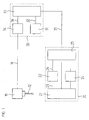
- FIG. 1 shows a block diagram of a preferred embodiment of a device according to the invention for coordinate measurement. It consists of a probe 10 with a stylus 12, position measuring units 20 for each coordinate axis to be measured, and a processing unit 30th
- the probe 10 generates a switching signal when the stylus 12 is deflected upon contact of a workpiece.
- the switching signal passes via a switching line 11 to the processing unit 30 and signals that the probing process has ended.
- the switching line 11 may be both a conventional cable connection and an infrared transmission link.
- the processing unit 30 is, in principle, a numerical controller. It contains, among other control loops, which are adapted to control drives that position the probe 10. Such numerical controls are known and not the subject of the present Invention. In the following, therefore, only functions are described that are relevant to the invention.
- control clock generator 31 In the processing unit 30 are a control clock generator 31; a control unit 33 and a time measuring unit 34.
- the controller clock generator 31 provides the control unit 33 with a regulator clock signal 32 a time base which determines the frequency with which the control circuits in the control unit 33 operate or in which time intervals position measurement values are requested from the position measurement units 20.
- the period duration of the regulator clock signal 32 is also referred to as cycle time.
- the control unit 33 controls the probing process. For requesting and transmitting position measured values, it is connected to the position measuring unit 20 via a first data transmission channel 35. In this preferred embodiment, the data transmission takes place in serial form.
- the time measuring unit 34 serves to measure a time period ⁇ t between the start of a regulator clock period and a switching event on the probe 10. In this case, either the rising edge or the falling edge of the regulator clock signal 32 is usually selected as the beginning of a regulator clock period.
- the time measuring unit 34 is connected to the control unit 33 via a second data transmission channel 36. In addition, it is fed to the switching signal of the probe 10 via the switching line 11. Via the second data transmission channel 36, the time measuring unit 34 is reset by the control unit 33 at the beginning of each controller clock period and restarted. In addition, the control unit 33 is signaled via the second data transmission channel 35, the arrival of a switching event and the time period .DELTA.t transmitted.
- the position measuring unit 20 is composed of a position measuring device 21, a sampling clock generator 22, a position data memory 24 and an interface unit 25. Although in FIG. 1 Only one position measuring unit 20 is shown, it is obvious to those skilled in that ever after the number of coordinate axes to be measured several position measuring units 20 are required.
- both the sampling clock generator 22 and the position data memory 24 are located in the position measuring unit 20 is particularly advantageous because it reduces the number of position values which have to be transmitted to the processing unit 30.
- This advantage is particularly evident when the data exchange between the position measuring unit 20 and the processing unit 30 takes place via a serial interface. For example, if the data transfer rate is 2 Mbps, the serial transfer of a 32-bit position value takes at least 16 ⁇ s. If, as the cycle time of the processing unit 30, one assumes the above-mentioned 50 ⁇ s, this would mean that only a maximum of two additional position values could be measured per period of the regulator clock signal 32. This restriction is made by the in FIG. 1 proposed construction of the position measuring unit 20 bypassed.
- the sampling clock generator 22 generates a sampling clock signal 23, which specifies a time grid in which position values are requested by the position measuring device 21 during the probing process.
- the sampling clock signal 23 has a higher frequency than the regulator clock signal 32. It is particularly advantageous if an integer multiple of the frequency of the regulator clock signal 32 is selected for the frequency of the sampling clock signal 23. In addition, it is advantageous to synchronize the sample clock signal 23 with the regulator clock signal 32 to provide an exact time reference between the two clock signals.
- the interface unit 25 is connected to the control unit 33 via the first data transmission channel 35. Position values can either be requested from the position data memory 24 or directly from the position measuring device 21 and transmitted to the control unit 33 via the interface unit 25. It also provides the sampling clock generator 22 with a synchronization signal 26 and stops detection and storage of position values when it is transmitted via the first data transmission channel 35, a corresponding command.
- the position data are stored in the position data memory 24.
- the position data memory 24 must comprise at least as many memory cells that, after the end of the probing process, the position value closest in time to the probing time is located in the position data memory 24. Memory cells that contain position values that are no longer needed can be overwritten. Therefore, it is advantageous if the position data memory 24 is designed as cyclically overwritable ring memory, i. that the position value currently to be stored overwrites the oldest, no longer required position value in the position data memory 24.
- the determination of the memory requirement for the position data memory 24 will be explained in the following example. If the frequency of the sampling clock signal 23 corresponds to ten times the frequency of the regulator clock signal 32 and the communication between the processing unit 30 and the position measuring unit 20 is time-discretely spaced apart from the period of the regulator clock signal 32, ten position values must be stored per control clock period. This is due to the fact that the switching signal from the probe 10 can arrive at any time between two communication times. Each of the position values in the position data memory 24, which has been measured since the last access of the processing unit 30 to the position measuring unit 20, can therefore be the closest to the switching signal.
- Position values from the position measuring devices 21 are continuously requested by the control unit 33 at a time interval of the period duration of the regulator clock signal 32 via the first data transmission channel 35 and the interface unit 25.
- the control unit 33 requires these position values as actual position values for the control circuits for controlling the drives.
- the interface unit 25 synchronizes the sampling clock signal 23 with the regulator clock signal 32 via the synchronization signal 26.
- the timer unit 34 is reset and restarted by the control unit 33 via the second data transmission channel 36 at the beginning of each controller clock period. Parallel to this, position values are measured at the time interval of the period of the sampling clock signal 23 and stored in the position data memory 24.
- the probe 10 signals the processing unit 30 by a signal on the switching line 11 when the stylus 12 has been deflected upon contact of the workpiece. Thereafter, the control unit 33 stops the drives and the period ⁇ t between the start of the regulator clock period and the switching event is held in the time measuring unit 34.
- the position measuring unit 20 must be transmitted that no further position data is required. This can be done, for example, in FIG. 1 by the transmission of a command word via the first data transmission channel 35 to the interface unit 25 done.
- the switching line 11 could be additionally connected to the position measuring unit 20 (not shown) and stop the sampling clock generator 22 in the event of a switching event.
- the position value closest to the switching event can now be determined in the position data memory 24 in the control unit 33 and sent to the control unit 33 for further processing via the first data transmission channel 35 and the interface unit 25 be transmitted.
- the transit time of the switching signal is included in the processing unit 30 until it arrives. This is especially true when the switching line 11 is not formed as an electrical line, but as a wireless transmission link, in which the switching signal is transmitted, for example, with the aid of infrared light pulses.
- the duration of the switching signal can be stored for example in the control unit. The determination of the signal transit time is not the subject of the present invention.
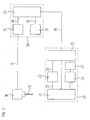
- FIG. 2 shows a block diagram of another embodiment of a device according to the invention for coordinate measurement. Unlike in FIG. 1 illustrated example includes each position measuring unit 20 in FIG. 2 additionally an evaluation unit 27. The further structure corresponds to that of FIG. 1 , The same components are provided with the same reference numerals. Their explanation is waived.
- the control unit 33 transmits the time interval .DELTA.t measured by the time measuring unit 34 via the first data transmission channel 35 and the interface unit 25 to the evaluation unit 27. Based on the time interval .DELTA.t, this determines the position value closest to the detection instant in the position data memory 24 and transmits it to the processing unit 30 ,
- the transit time of the switching signal can be taken into account in this example in that either the control unit 33 corrects the measured time interval .DELTA.t by the signal propagation time and transmits the corrected value to the evaluation unit 27, or the evaluation unit 27 includes the signal propagation time in the determination of the result.
- control unit 33 which is heavily utilized during the probing process, is considerably relieved thereby.
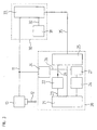
- FIG. 3 finally shows a block diagram of a third embodiment of the present invention.
- the time measuring unit 34 is no longer in the processing unit 30. Instead, in each position measuring unit 20, there is one Timing unit 34 is provided.
- As in the embodiment of FIG. 2 also include the position measuring units 20 in the example of FIG. 3 an evaluation unit 27.
- the further structure corresponds to that of FIG. 1 so he will not be described again.
- the same components are provided with the same reference numerals.
- the switching line 11 via which the probe 10 outputs the switching signal is connected to each time measuring unit 34 and to the control unit 33 in the processing unit 30.
- the connection to the time measuring unit 34 serves to stop the time measurement when a switching signal occurs.
- the control unit 33 is notified via the switching line 11 that the probing process has ended and thus the drives are stopped and the position values associated with the probing event can be requested from the position measuring units 20.
- the switching line 11 is connected to a plurality of spatially separated components, it is particularly advantageous if the connection is not via electrical lines, but via wireless transmission links. Suitable wireless transmission links can be formed, for example, by radio-frequency transmitting and receiving units or also by infrared transmitters and receivers.
- the synchronization signal 26 is supplied not only to the sampling clock generator 22 but also to the time measuring unit 34.
- the time measuring unit 34 can be reset at each position data request. Since the position data requests continue to occur discretely in time intervals of the regulator clock signal 32, the time interval .DELTA.t between a pulse of the regulator clock signal 32 and the occurrence of the switching signal on the switching probe 10 can thus still be measured in the time measuring unit 34.
- the time measuring unit 34 is connected to the evaluation unit 27 via the second data transmission channel 36.
- the time interval .DELTA.t measured by the time measuring unit 34 can be transmitted to the evaluation unit 27 via this. With this information, it is the evaluation unit 27 again It is possible to determine the position value closest to the time of occurrence of the switching signal on the switching probe 10 in the position data memory 24. In this exemplary embodiment too, it is advantageous if the evaluation unit 27 takes into account the transit time of the switching signal when determining the position value closest to the switching event.
- the resulting position value can either be transmitted automatically or at the request of the processing unit 30 from the evaluation unit 27 via the interface unit 25 and the first data transmission channel 35 to the control unit 33.
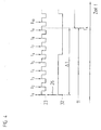
- FIG. 4 shows a simplified timing diagram of a method according to the invention for coordinate measurement in which the temporal relationship between the control clock signal 32, sampling clock signal 23 and the switching line 11 of the probe 10 is shown again in detail.
- the sampling clock signal 23 has ten times the frequency of the regulator clock signal 32.
- a regulator clock period begins with a rising edge of the regulator clock signal 32.
- the time measurement unit 34 is reset and restarted via the second communication channel 36.
- a position value is requested from the position measuring unit 20 by the control unit 33 via the first data transmission channel 35 and the interface unit 25.
- the sampling clock signal 23 is synchronized with the regulator clock signal 32 via the synchronization signal 26.
- position values are measured and stored in the position data memory 24.
- a level change on the switching line 11 signals the contact of the stylus 12 with the workpiece.
- the time measurement in the time measuring unit 34 is stopped and the exact timing of the switching signal with respect to the rising edge of the regulator clock signal 32 is available in the form of the measured time period ⁇ t.
- the time interval .DELTA.t is transmitted via the second transmission channel 36 to the control unit 33, which subsequently determines the position value closest to the switching event.
- the position value can finally be transmitted via the first data transmission channel 35 to the control unit 33 and further processed there.
- the accuracy of the result can be further improved by interpolation.
- This requires the position value before and the position value after the contact time t k , as well as the value of the period .DELTA.t. Since the feed rate of the probe 10 during the probing process can be assumed to be constant, there is a linear relationship between the two position values, via which the exact position value can be interpolated after the time span ⁇ t has elapsed.
Landscapes
- Physics & Mathematics (AREA)
- General Physics & Mathematics (AREA)
- Length Measuring Devices With Unspecified Measuring Means (AREA)
- A Measuring Device Byusing Mechanical Method (AREA)
- Measurement Of Length, Angles, Or The Like Using Electric Or Magnetic Means (AREA)
Applications Claiming Priority (3)
| Application Number | Priority Date | Filing Date | Title |
|---|---|---|---|
| DE102004026022 | 2004-05-27 | ||
| DE102005011285A DE102005011285A1 (de) | 2004-05-27 | 2005-03-11 | Vorrichtung und Verfahren zur Koordinatenmessung |
| PCT/EP2005/003966 WO2005119173A1 (de) | 2004-05-27 | 2005-04-15 | Vorrichtung und verfahren zur koordinatenmessung |
Publications (2)
| Publication Number | Publication Date |
|---|---|
| EP1754019A1 EP1754019A1 (de) | 2007-02-21 |
| EP1754019B1 true EP1754019B1 (de) | 2009-04-01 |
Family
ID=34965083
Family Applications (1)
| Application Number | Title | Priority Date | Filing Date |
|---|---|---|---|
| EP05733655A Expired - Lifetime EP1754019B1 (de) | 2004-05-27 | 2005-04-15 | Vorrichtung und verfahren zur koordinatenmessung |
Country Status (6)
| Country | Link |
|---|---|
| US (1) | US7367133B2 (enExample) |
| EP (1) | EP1754019B1 (enExample) |
| JP (1) | JP4956424B2 (enExample) |
| AT (1) | ATE427476T1 (enExample) |
| DE (2) | DE102005011285A1 (enExample) |
| WO (1) | WO2005119173A1 (enExample) |
Families Citing this family (14)
| Publication number | Priority date | Publication date | Assignee | Title |
|---|---|---|---|---|
| GB0518078D0 (en) * | 2005-09-06 | 2005-10-12 | Renishaw Plc | Signal transmission system |
| DE102006054978A1 (de) * | 2006-11-22 | 2008-05-29 | Dr. Johannes Heidenhain Gmbh | Tastsystem |
| GB0703423D0 (en) * | 2007-02-22 | 2007-04-04 | Renishaw Plc | Calibration method and apparatus |
| GB0900878D0 (en) * | 2009-01-20 | 2009-03-04 | Renishaw Plc | Method for optimising a measurement cycle |
| JP5276488B2 (ja) * | 2009-03-20 | 2013-08-28 | 株式会社森精機製作所 | 工作機械における工作物測定装置およびその方法 |
| JP5424676B2 (ja) * | 2009-03-13 | 2014-02-26 | キヤノン株式会社 | 画像処理装置 |
| US20100269232A1 (en) * | 2009-04-17 | 2010-10-21 | Richard Kenton Workman | Scanning Probe Microscope that Outputs Metadata with Image |
| CN102814707B (zh) * | 2012-08-14 | 2015-02-18 | 西安理工大学 | 一种触发式传感器触发行程的测定装置及方法 |
| DE102013219277A1 (de) * | 2013-09-25 | 2015-03-26 | Dr. Johannes Heidenhain Gmbh | Positionsmesseinrichtung und Verfahren zur Überprüfung eines Arbeitstaktsignals |
| US10215547B2 (en) * | 2016-06-24 | 2019-02-26 | Mitutoyo Corporation | Method for operating a coordinate measuring machine |
| GB201700879D0 (en) * | 2017-01-18 | 2017-03-01 | Renishaw Plc | Machine tool apparatus |
| DE102018204696B4 (de) * | 2018-03-27 | 2025-12-24 | Carl Zeiss Industrielle Messtechnik Gmbh | Verfahren und Anordnung zum Erfassen eines Objekts mittels eines bewegbaren Sensors |
| DE102019122655A1 (de) * | 2019-08-22 | 2021-02-25 | M & H Inprocess Messtechnik Gmbh | Messsystem |
| DE102019122650A1 (de) * | 2019-08-22 | 2021-02-25 | M & H Inprocess Messtechnik Gmbh | Messsystem |
Family Cites Families (18)
| Publication number | Priority date | Publication date | Assignee | Title |
|---|---|---|---|---|
| JPS5782707A (en) * | 1980-11-10 | 1982-05-24 | Toyoda Mach Works Ltd | Method and device for measuring curved surface shape |
| US4484118A (en) | 1981-08-29 | 1984-11-20 | Toshiba Kikai Kabushiki Kaisha | Method and apparatus for measuring a workpiece |
| JPS58127110A (ja) * | 1981-10-07 | 1983-07-28 | Toshiba Mach Co Ltd | 計測方法および計測装置 |
| JPH057526Y2 (enExample) * | 1987-08-05 | 1993-02-25 | ||
| GB8908854D0 (en) * | 1989-04-19 | 1989-06-07 | Renishaw Plc | Method of and apparatus for scanning the surface of a workpiece |
| US5189806A (en) * | 1988-12-19 | 1993-03-02 | Renishaw Plc | Method of and apparatus for scanning the surface of a workpiece |
| DE4245012B4 (de) * | 1992-04-14 | 2004-09-23 | Carl Zeiss | Verfahren zur Messung von Formelementen auf einem Koordinatenmeßgerät |
| IT1279590B1 (it) * | 1995-05-11 | 1997-12-16 | Marposs Spa | Sistema e metodo di trasmissione di segnali via etere fra una testa di controllo e un ricevitore remoto |
| DE19525592A1 (de) * | 1995-07-13 | 1997-01-16 | Zeiss Carl Fa | Verfahren zur Koordinatenmessung an Werkstücken |
| JPH10132549A (ja) * | 1996-10-25 | 1998-05-22 | Ricoh Co Ltd | 形状測定装置 |
| US6044569A (en) * | 1997-02-10 | 2000-04-04 | Mitutoyo Corporation | Measuring method and measuring instrument |
| DE19929557B4 (de) * | 1999-06-18 | 2006-01-19 | Dr. Johannes Heidenhain Gmbh | Verfahren und Schaltkreis zur Einstellung einer Schaltschwelle eines Tastschalters |
| US6704684B2 (en) | 1999-10-22 | 2004-03-09 | Carl-Zeiss-Stiftung | Method for determining measuring points on a workpiece and a measuring system therefor |
| DE10050795C2 (de) | 1999-12-23 | 2002-11-07 | Klingelnberg Gmbh | Verfahren und Vorrichtung zum Scannen auf einem Koordinatenmessgerät |
| DE10020842A1 (de) | 2000-04-28 | 2001-10-31 | Zeiss Carl | Koordinatenmeßgerät oder Werkzeugmaschine |
| DE60227431D1 (de) * | 2001-02-02 | 2008-08-14 | Renishaw Plc | Durch Biegung des Fühlers konfigurierbare Messsonde für eine Werkzeugmachine |
| GB0308149D0 (en) * | 2003-04-09 | 2003-05-14 | Renishaw Plc | Probe for sensing the position of an object |
| DE102004035926A1 (de) * | 2004-07-23 | 2006-03-16 | Dr. Johannes Heidenhain Gmbh | Tastkopf |
-
2005
- 2005-03-11 DE DE102005011285A patent/DE102005011285A1/de not_active Withdrawn
- 2005-04-15 EP EP05733655A patent/EP1754019B1/de not_active Expired - Lifetime
- 2005-04-15 JP JP2007513713A patent/JP4956424B2/ja not_active Expired - Fee Related
- 2005-04-15 DE DE502005007000T patent/DE502005007000D1/de not_active Expired - Lifetime
- 2005-04-15 WO PCT/EP2005/003966 patent/WO2005119173A1/de not_active Ceased
- 2005-04-15 AT AT05733655T patent/ATE427476T1/de not_active IP Right Cessation
- 2005-04-15 US US11/597,445 patent/US7367133B2/en not_active Expired - Lifetime
Also Published As
| Publication number | Publication date |
|---|---|
| EP1754019A1 (de) | 2007-02-21 |
| WO2005119173A1 (de) | 2005-12-15 |
| DE102005011285A1 (de) | 2005-12-15 |
| DE502005007000D1 (de) | 2009-05-14 |
| ATE427476T1 (de) | 2009-04-15 |
| JP4956424B2 (ja) | 2012-06-20 |
| US7367133B2 (en) | 2008-05-06 |
| US20070245584A1 (en) | 2007-10-25 |
| JP2008500520A (ja) | 2008-01-10 |
Similar Documents
| Publication | Publication Date | Title |
|---|---|---|
| EP1754019B1 (de) | Vorrichtung und verfahren zur koordinatenmessung | |
| EP2718677B1 (de) | Hochpräzise synchronisierte messwerterfassung | |
| DE69309588T2 (de) | Verfahren und Gerät zum Abtasten der Oberfläche eines Werkstückes | |
| EP3240994B1 (de) | Erfassung von geometrischen abweichungen einer bewegungsführung bei einem koordinatenmessgerät oder einer werkzeugmaschine | |
| EP3840916B1 (de) | Werkzeugkontrolle in einer werkstückbearbeitungsmaschine | |
| DE102018218298A1 (de) | Bearbeitungssystem | |
| DE2754732B2 (de) | Automatisches Meßverfahren für eine numerisch gesteuerte Werkzeugmaschine und Vorrichtung zur Durchführung dieses Verfahrens | |
| EP2960737B1 (de) | Vorrichtung und verfahren zum erzeugen eines triggersignals in einer positionsmesseinrichtung und positionsmesseinrichtung hierzu | |
| EP4029185B1 (de) | Vorrichtung und verfahren zur synchron-seriellen datenübertragung | |
| DE20122613U1 (de) | Vorrichtung zur seriellen Datenübertragung zwischen einem Positionsmesssystem und einer Verarbeitungseinheit | |
| DE102012022116A1 (de) | Messvorrichtung für eine Werkzeugmaschine | |
| EP1170643B1 (de) | Verfahren und Vorrichtung zur seriellen Datenübertragung zwischen einem Positionsmesssystem und einer Verarbeitungseinheit | |
| EP4018159B1 (de) | Messsystem | |
| EP3267272B1 (de) | Vorrichtung und verfahren zur datenübertragung | |
| DE1552254A1 (de) | Bohrwerk | |
| DE3709129C2 (enExample) | ||
| DE10111630A1 (de) | Verfahren zum Betrieb einer Positionsmesseinrichtung und hierzu geeignete Positionsmesseinrichtung | |
| DE19815647C2 (de) | Verfahren zur Synchronisation einer lokalen auf eine zentrale Zeitbasis, und Vorrichtung zur Durchführung des Verfahrens mit bevorzugten Verwendungen | |
| DE112015006524B4 (de) | Numerische Steuerungseinrichtung | |
| EP4018160B1 (de) | Vorrichtung zur kalibrierung einer geschwindigkeit einer bewegungsachse einer maschine | |
| DE102010064123B3 (de) | Verfahren zum Ansteuern von Peripheriegeräten eines taktsynchron arbeitenden Bussystems und von Fremdperipheriegeräten eines Fremdbussystems sowie zugehöriger Busumsetzer | |
| DE102007020440B4 (de) | Synchronisationsbussystem, Kommunikationseinheiten für ein Synchronisationsbussystem und Verfahren zum Austauschen von Nachrichten zur zeitlichen Synchronisation | |
| WO2001053775A1 (de) | Scannen mit positionsgebung zur triggerung der messwertaufnahme | |
| WO2021032443A1 (de) | Messsystem | |
| DE102006020680A1 (de) | Verfahren und Vorrichtung zum positionsgenauen Triggern eines wahlweise aktivierbaren Maschinenteils |
Legal Events
| Date | Code | Title | Description |
|---|---|---|---|
| PUAI | Public reference made under article 153(3) epc to a published international application that has entered the european phase |
Free format text: ORIGINAL CODE: 0009012 |
|
| 17P | Request for examination filed |
Effective date: 20061227 |
|
| AK | Designated contracting states |
Kind code of ref document: A1 Designated state(s): AT BE BG CH CY CZ DE DK EE ES FI FR GB GR HU IE IS IT LI LT LU MC NL PL PT RO SE SI SK TR |
|
| DAX | Request for extension of the european patent (deleted) | ||
| GRAC | Information related to communication of intention to grant a patent modified |
Free format text: ORIGINAL CODE: EPIDOSCIGR1 |
|
| GRAP | Despatch of communication of intention to grant a patent |
Free format text: ORIGINAL CODE: EPIDOSNIGR1 |
|
| GRAS | Grant fee paid |
Free format text: ORIGINAL CODE: EPIDOSNIGR3 |
|
| GRAA | (expected) grant |
Free format text: ORIGINAL CODE: 0009210 |
|
| AK | Designated contracting states |
Kind code of ref document: B1 Designated state(s): AT BE BG CH CY CZ DE DK EE ES FI FR GB GR HU IE IS IT LI LT LU MC NL PL PT RO SE SI SK TR |
|
| REG | Reference to a national code |
Ref country code: GB Ref legal event code: FG4D Free format text: NOT ENGLISH |
|
| REG | Reference to a national code |
Ref country code: CH Ref legal event code: EP |
|
| REG | Reference to a national code |
Ref country code: IE Ref legal event code: FG4D Free format text: LANGUAGE OF EP DOCUMENT: GERMAN |
|
| REF | Corresponds to: |
Ref document number: 502005007000 Country of ref document: DE Date of ref document: 20090514 Kind code of ref document: P |
|
| PG25 | Lapsed in a contracting state [announced via postgrant information from national office to epo] |
Ref country code: SI Free format text: LAPSE BECAUSE OF FAILURE TO SUBMIT A TRANSLATION OF THE DESCRIPTION OR TO PAY THE FEE WITHIN THE PRESCRIBED TIME-LIMIT Effective date: 20090401 |
|
| NLV1 | Nl: lapsed or annulled due to failure to fulfill the requirements of art. 29p and 29m of the patents act | ||
| REG | Reference to a national code |
Ref country code: IE Ref legal event code: FD4D |
|
| PG25 | Lapsed in a contracting state [announced via postgrant information from national office to epo] |
Ref country code: PT Free format text: LAPSE BECAUSE OF FAILURE TO SUBMIT A TRANSLATION OF THE DESCRIPTION OR TO PAY THE FEE WITHIN THE PRESCRIBED TIME-LIMIT Effective date: 20090902 Ref country code: EE Free format text: LAPSE BECAUSE OF FAILURE TO SUBMIT A TRANSLATION OF THE DESCRIPTION OR TO PAY THE FEE WITHIN THE PRESCRIBED TIME-LIMIT Effective date: 20090401 Ref country code: LT Free format text: LAPSE BECAUSE OF FAILURE TO SUBMIT A TRANSLATION OF THE DESCRIPTION OR TO PAY THE FEE WITHIN THE PRESCRIBED TIME-LIMIT Effective date: 20090401 Ref country code: FI Free format text: LAPSE BECAUSE OF FAILURE TO SUBMIT A TRANSLATION OF THE DESCRIPTION OR TO PAY THE FEE WITHIN THE PRESCRIBED TIME-LIMIT Effective date: 20090401 Ref country code: ES Free format text: LAPSE BECAUSE OF FAILURE TO SUBMIT A TRANSLATION OF THE DESCRIPTION OR TO PAY THE FEE WITHIN THE PRESCRIBED TIME-LIMIT Effective date: 20090712 |
|
| BERE | Be: lapsed |
Owner name: DR. JOHANNES HEIDENHAIN G.M.B.H. Effective date: 20090430 |
|
| PG25 | Lapsed in a contracting state [announced via postgrant information from national office to epo] |
Ref country code: PL Free format text: LAPSE BECAUSE OF FAILURE TO SUBMIT A TRANSLATION OF THE DESCRIPTION OR TO PAY THE FEE WITHIN THE PRESCRIBED TIME-LIMIT Effective date: 20090401 Ref country code: NL Free format text: LAPSE BECAUSE OF FAILURE TO SUBMIT A TRANSLATION OF THE DESCRIPTION OR TO PAY THE FEE WITHIN THE PRESCRIBED TIME-LIMIT Effective date: 20090401 Ref country code: IS Free format text: LAPSE BECAUSE OF FAILURE TO SUBMIT A TRANSLATION OF THE DESCRIPTION OR TO PAY THE FEE WITHIN THE PRESCRIBED TIME-LIMIT Effective date: 20090801 Ref country code: SE Free format text: LAPSE BECAUSE OF FAILURE TO SUBMIT A TRANSLATION OF THE DESCRIPTION OR TO PAY THE FEE WITHIN THE PRESCRIBED TIME-LIMIT Effective date: 20090701 |
|
| REG | Reference to a national code |
Ref country code: CH Ref legal event code: PL |
|
| PG25 | Lapsed in a contracting state [announced via postgrant information from national office to epo] |
Ref country code: LI Free format text: LAPSE BECAUSE OF NON-PAYMENT OF DUE FEES Effective date: 20090430 Ref country code: CH Free format text: LAPSE BECAUSE OF NON-PAYMENT OF DUE FEES Effective date: 20090430 Ref country code: CZ Free format text: LAPSE BECAUSE OF FAILURE TO SUBMIT A TRANSLATION OF THE DESCRIPTION OR TO PAY THE FEE WITHIN THE PRESCRIBED TIME-LIMIT Effective date: 20090401 Ref country code: RO Free format text: LAPSE BECAUSE OF FAILURE TO SUBMIT A TRANSLATION OF THE DESCRIPTION OR TO PAY THE FEE WITHIN THE PRESCRIBED TIME-LIMIT Effective date: 20090401 Ref country code: DK Free format text: LAPSE BECAUSE OF FAILURE TO SUBMIT A TRANSLATION OF THE DESCRIPTION OR TO PAY THE FEE WITHIN THE PRESCRIBED TIME-LIMIT Effective date: 20090401 Ref country code: IE Free format text: LAPSE BECAUSE OF FAILURE TO SUBMIT A TRANSLATION OF THE DESCRIPTION OR TO PAY THE FEE WITHIN THE PRESCRIBED TIME-LIMIT Effective date: 20090401 |
|
| PLBE | No opposition filed within time limit |
Free format text: ORIGINAL CODE: 0009261 |
|
| STAA | Information on the status of an ep patent application or granted ep patent |
Free format text: STATUS: NO OPPOSITION FILED WITHIN TIME LIMIT |
|
| PG25 | Lapsed in a contracting state [announced via postgrant information from national office to epo] |
Ref country code: SK Free format text: LAPSE BECAUSE OF FAILURE TO SUBMIT A TRANSLATION OF THE DESCRIPTION OR TO PAY THE FEE WITHIN THE PRESCRIBED TIME-LIMIT Effective date: 20090401 |
|
| 26N | No opposition filed |
Effective date: 20100105 |
|
| PG25 | Lapsed in a contracting state [announced via postgrant information from national office to epo] |
Ref country code: BG Free format text: LAPSE BECAUSE OF FAILURE TO SUBMIT A TRANSLATION OF THE DESCRIPTION OR TO PAY THE FEE WITHIN THE PRESCRIBED TIME-LIMIT Effective date: 20090701 |
|
| PG25 | Lapsed in a contracting state [announced via postgrant information from national office to epo] |
Ref country code: MC Free format text: LAPSE BECAUSE OF NON-PAYMENT OF DUE FEES Effective date: 20090430 |
|
| PG25 | Lapsed in a contracting state [announced via postgrant information from national office to epo] |
Ref country code: BE Free format text: LAPSE BECAUSE OF NON-PAYMENT OF DUE FEES Effective date: 20090430 |
|
| PG25 | Lapsed in a contracting state [announced via postgrant information from national office to epo] |
Ref country code: AT Free format text: LAPSE BECAUSE OF NON-PAYMENT OF DUE FEES Effective date: 20090415 |
|
| PG25 | Lapsed in a contracting state [announced via postgrant information from national office to epo] |
Ref country code: GR Free format text: LAPSE BECAUSE OF FAILURE TO SUBMIT A TRANSLATION OF THE DESCRIPTION OR TO PAY THE FEE WITHIN THE PRESCRIBED TIME-LIMIT Effective date: 20090702 |
|
| PG25 | Lapsed in a contracting state [announced via postgrant information from national office to epo] |
Ref country code: LU Free format text: LAPSE BECAUSE OF NON-PAYMENT OF DUE FEES Effective date: 20090415 |
|
| PG25 | Lapsed in a contracting state [announced via postgrant information from national office to epo] |
Ref country code: HU Free format text: LAPSE BECAUSE OF FAILURE TO SUBMIT A TRANSLATION OF THE DESCRIPTION OR TO PAY THE FEE WITHIN THE PRESCRIBED TIME-LIMIT Effective date: 20091002 |
|
| PG25 | Lapsed in a contracting state [announced via postgrant information from national office to epo] |
Ref country code: TR Free format text: LAPSE BECAUSE OF FAILURE TO SUBMIT A TRANSLATION OF THE DESCRIPTION OR TO PAY THE FEE WITHIN THE PRESCRIBED TIME-LIMIT Effective date: 20090401 |
|
| PG25 | Lapsed in a contracting state [announced via postgrant information from national office to epo] |
Ref country code: CY Free format text: LAPSE BECAUSE OF FAILURE TO SUBMIT A TRANSLATION OF THE DESCRIPTION OR TO PAY THE FEE WITHIN THE PRESCRIBED TIME-LIMIT Effective date: 20090401 |
|
| REG | Reference to a national code |
Ref country code: FR Ref legal event code: PLFP Year of fee payment: 12 |
|
| REG | Reference to a national code |
Ref country code: FR Ref legal event code: PLFP Year of fee payment: 13 |
|
| REG | Reference to a national code |
Ref country code: FR Ref legal event code: PLFP Year of fee payment: 14 |
|
| PGFP | Annual fee paid to national office [announced via postgrant information from national office to epo] |
Ref country code: IT Payment date: 20190429 Year of fee payment: 15 |
|
| PGFP | Annual fee paid to national office [announced via postgrant information from national office to epo] |
Ref country code: GB Payment date: 20190418 Year of fee payment: 15 |
|
| PG25 | Lapsed in a contracting state [announced via postgrant information from national office to epo] |
Ref country code: FR Free format text: LAPSE BECAUSE OF NON-PAYMENT OF DUE FEES Effective date: 20190430 |
|
| PGFP | Annual fee paid to national office [announced via postgrant information from national office to epo] |
Ref country code: DE Payment date: 20200420 Year of fee payment: 16 |
|
| GBPC | Gb: european patent ceased through non-payment of renewal fee |
Effective date: 20200415 |
|
| PG25 | Lapsed in a contracting state [announced via postgrant information from national office to epo] |
Ref country code: GB Free format text: LAPSE BECAUSE OF NON-PAYMENT OF DUE FEES Effective date: 20200415 |
|
| PG25 | Lapsed in a contracting state [announced via postgrant information from national office to epo] |
Ref country code: IT Free format text: LAPSE BECAUSE OF NON-PAYMENT OF DUE FEES Effective date: 20200415 |
|
| REG | Reference to a national code |
Ref country code: DE Ref legal event code: R119 Ref document number: 502005007000 Country of ref document: DE |
|
| PG25 | Lapsed in a contracting state [announced via postgrant information from national office to epo] |
Ref country code: DE Free format text: LAPSE BECAUSE OF NON-PAYMENT OF DUE FEES Effective date: 20211103 |