EP1753936B1 - Sealing system - Google Patents
Sealing system Download PDFInfo
- Publication number
- EP1753936B1 EP1753936B1 EP05732858.5A EP05732858A EP1753936B1 EP 1753936 B1 EP1753936 B1 EP 1753936B1 EP 05732858 A EP05732858 A EP 05732858A EP 1753936 B1 EP1753936 B1 EP 1753936B1
- Authority
- EP
- European Patent Office
- Prior art keywords
- seal
- sealing system
- sealing
- tubular conduit
- backup
- Prior art date
- Legal status (The legal status is an assumption and is not a legal conclusion. Google has not performed a legal analysis and makes no representation as to the accuracy of the status listed.)
- Expired - Lifetime
Links
Images


Classifications
-
- E—FIXED CONSTRUCTIONS
- E21—EARTH OR ROCK DRILLING; MINING
- E21B—EARTH OR ROCK DRILLING; OBTAINING OIL, GAS, WATER, SOLUBLE OR MELTABLE MATERIALS OR A SLURRY OF MINERALS FROM WELLS
- E21B33/00—Sealing or packing boreholes or wells
- E21B33/10—Sealing or packing boreholes or wells in the borehole
- E21B33/12—Packers; Plugs
- E21B33/1208—Packers; Plugs characterised by the construction of the sealing or packing means
- E21B33/1216—Anti-extrusion means, e.g. means to prevent cold flow of rubber packing
-
- E—FIXED CONSTRUCTIONS
- E21—EARTH OR ROCK DRILLING; MINING
- E21B—EARTH OR ROCK DRILLING; OBTAINING OIL, GAS, WATER, SOLUBLE OR MELTABLE MATERIALS OR A SLURRY OF MINERALS FROM WELLS
- E21B33/00—Sealing or packing boreholes or wells
- E21B33/10—Sealing or packing boreholes or wells in the borehole
- E21B33/12—Packers; Plugs
- E21B33/129—Packers; Plugs with mechanical slips for hooking into the casing
- E21B33/1293—Packers; Plugs with mechanical slips for hooking into the casing with means for anchoring against downward and upward movement
Definitions
- This invention relates to a sealing system for sealing a tubular conduit, particularly to seals for use in the oil and gas industry.
- Sealing systems are widely used in oil and gas extraction wells to provide a barrier to well fluids, well treatments, well interventions and well pressure. Some sealing systems are designed to seal a bore and others to provide a barrier or seal in the annulus between two seals, for example, straddling a leak in the production pipe.
- the sealing system is designed to be run through a narrow bore prior to locating and operating within a wider bore.
- Such systems are known as “through tubing” sealing systems.
- These applications often deem that the device is required to operate in a well bore greater than 15% of its original diameter.
- Such systems are known as “high expansion through tubing” sealing systems.
- a further disadvantage of conventional mechanical "through tubing" seals is that they rely on the initial pack off force applied to the sealing element in order to generate an effective seal. As well temperatures and pressures change, this induces changes to sealing forces. In the event that the seal pressure reduces due to cooling of the well bore, the performance of the seal may be compromised.
- US 3,371,716 which is considered the clorest prior art, discloses a well tool having slips and a sealing element and an elastomeric expander member with high hardness relative to the sealing element, whereby the expander functions to expand the slips as well as preventing extrusion of the packing.
- US 2,738,018 discloses a packer which has packing elements biased into a collapse position by springs.
- a sealing system for sealing a tubular conduit including:
- the anchor surface provides a secure anchor to the tubular conduit.
- a separate anchor is not essential. This has a number of advantages over conventional through tubing seal systems, for example, the displacement necessary to set the seal in place is reduced and the overall length of the system being used to carry the seal is also reduced.
- the seal forms a "cup” or “lip” contact seal with the tubular conduit.
- the at least one annular seal has a diverging cross section extending from the housing outer surface to the tubular conduit.
- a diverging cross-section facilitates the forming of a contact seal with the tubular conduit.
- the diverging geometry also facilitates energisation of the seal when pressure is applied.
- the at least one annular seal is self-energising.
- Self energising means that once the seal has made a contact seal with the tubular conduit, pressure applied to the seal system by the internal pressure within the tubular conduit, or annulus, forces the first portion of the at least one annular seal into tighter engagement with the tubular conduit and the second portion of the at least one annular seal to press the at least one seal backup anchor surface into tighter engagement with the tubular conduit wall.
- the seal backup comprises a series of interleaved elements.
- the interleaved elements are mounted externally onto the at least one annular seal or bonded into the at least one annular seal.
- the interleaved elements like the petals on a closed flower, allow the at least one seal backup to expand sufficiently for the anchor surface to engage with the tubular conduit.
- the at least one seal backup comprises an inner seal backup and an outer seal backup.
- both the inner seal backup and the outer seal backup comprise a series of interleaved elements.
- the inner seal backup and the outer seal backup are offset with respect to each other so that the leaved elements of the inner seal backup overlap the gaps left between the leaved elements of the outer seal backup as the interleaved elements open during the expansion of the at least one annular seal.
- the seal and anchor energising means includes an axially moveable sleeve mounted around the housing outer surface.
- An axially moveable sleeve facilitates applying an even pressure to expand the at least one seal around the entire circumference of the housing.
- the seal and anchor energising means further includes at least one spring element mounted to the housing outer surface adjacent the at least one annular seal.
- a spring element is used to transfer the axial displacement of the setting means to radial expansion of the at least one annular seal.
- the spring element also retains spring energy on the seal in order to keep it in sealing contact with the conduit wall.
- the at least one spring element is a beam spring.
- annular seals there are two annular seals, two seal backups and two sets of beam springs.
- Two annular seals, two seal backups and two sets of beam springs allow the sealing system to withstand pressures both above and below the seal system.
- each set of beam springs comprises a plurality of overlapping beam springs.
- the overlapping beam springs may be arranged axially with respect to the housing.
- the overlapping beam springs may be arranged helically with respect to the housing.
- Each set of overlapping beam springs may comprise an outer and inner layer of beam springs.
- the outer and inner layers may be arranged concentrically.
- the outer layer of beam springs may be arranged with a different helical angle to the inner layer of beam springs.
- the housing defines a throughbore.
- the housing is of solid cross section. If the housing defines a throughbore, hydrocarbons from below the seal will be able to flow to surface through the throughbore.
- a housing of solid cross-section can be used to seal the tubing.
- the seal system includes energy storing means for storing energy into the system after setting operation of the seal system is completed and to take up slack generated in the seal system by fluctuations in internal pressure and tempeature in the tubular conduit.
- the energy storing means is provided by the beam springs.
- the at least one annular seal is an elastomeric seal.
- the at least one annular seal is a plastic seal, a metal seal or a composite seal.
- a sealing system sealing a tubular conduit by a sealing system and anchoring the sealing system in the sealed tubular conduit, said method comprising the steps of:
- a seal back up for use in a sealing system for sealing a tubular conduit, the seal back up having an anchor surface for engaging the tubular conduit.
- the seal backup comprises a series of interleaved elements.
- the seal backup comprises an inner seal backup and an outer seal backup.
- part of the outer seal backup defines the anchor surface.
- the anchor surface provides a secure anchor to the tubular conduit to ensure the seal system cannot move under pressure.
- both the inner seal backup and the outer seal backup comprise a series of interleaved elements.
- the outer and inner seal back ups are made from metal.
- the outer and inner seal back ups are made from plastic, a composite or an elastomeric.
- a spring element for use in a sealing system for sealing a tubular conduit.
- the spring element is a beam spring.
- a sealing system for sealing a tubular conduit including at least one combined seal back up and anchor device.
- a tubular conduit may be sealed by a high expansion through tubing sealing system incorporating a combined seal back up and anchor.
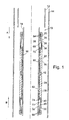
- FIG. 1 and 2 there is shown a cut-away side view of a sealing system 10 in according to a first embodiment of the present invention.
- the sealing system 10 has been run through tubing 12 into cased bore 14.
- the sealing system 10 comprises a cylindrical housing 16 having an outer surface 18, a setting sleeve 20, a first annular seal 22, having a sealing surface 76, and a second annular seal 24, having a sealing surface 78.
- the sealing system 10 also includes a first seal back-up 25 associated with the first annular seal 22 comprising a first outer seal backup 26 and a first inner seal backup 28, and a second seal back up 29 associated with the second annular seal 24 comprising a second outer seal backup 30 and a second inner seal backup 32.
- the first seal back up 25 is shown in Figs. 3a and 3b in the run in condition, i.e. the pre-deployment position also shown in Fig. 1 .
- Both the first outer seal back up 26 and the first inner seal back up 28 are made up of a number of overlapping leaved elements. In Fig.
- FIG. 3a five leaves 26a-e of the first outer seal backup 26 are shown, which overlap the gaps between the four leaves 28a-d of the inner seal backup 28 which are shown. It will be understood any number of leaves could be used and the leaves extend around the circumference of the housing outer surface 18. In Figs. 3a and 3b the inner leaves 28a-d are truncated for clarity, in reality they would extend to a similar length to the outer leaves 26a-e.
- the second seal backup 29 is of similar construction to the first seal backup 25.
- First beam springs 60 are shown in Fig. 4 , a perspective cut away view of part of the sealing system of Fig. 1 .
- First beam springs 60 are sandwiched between the first annular seal 22 and the housing outer surface 18.
- second beam springs 62 are sandwiched between the second annular seal 24 and the housing outer surface 18.
- the first beam springs 60 are interleaved such that when the first annular seal 22 is deployed and the beam springs arch outwards, as shown in Fig. 2 , the gap created between beam springs 60a and 60b is, at least partially, filled by beam spring 60c.
- the first beam springs 60 are arranged axially with respect to the housing 16.
- each beam spring 60,62 is a rectangular member of arcuate cross-section 63.
- the arrangement of the second beam springs 62 is the same as the arrangement of the first beam springs 60.
- first annular seal 22 is retained in position by a retainer 70
- second annular seal 24 is retained in position by retainer 74.
- the first outer seal backup 26 and the second outer seal backup 30 both have anchor seal surfaces 38,40 respectively for anchoring the sealing system 10 to the cased bore 14 when the seals 22,24 are activated.
- the first seal back up 25 is retained in the position shown in Fig. 1 by means of shear screws 64.
- the second seal back up 29 is retained in the position shown in Fig. 1 by means of fixed position screws 66.
- the setting sleeve 20 is moved axially down the cased bore 14 with respect to the housing 16 in the direction of arrow A under the action of an industry standard setting device (not shown). This applied load shears the shear screws 64 forcing the first seal backup 25 radially outwards and over the seal retainer 70 and the first annular seal 22 until the inner face 68 of the first inner seal back up 28 meets the retainer 70 of the first annular seal 22.
- the deployed sealing system 10 shown in Figure 2 can withstand pressure from both upwards and downwards directions, i.e. A & B axial directions, indeed, pressure increases will energise the seals 22,24 to improve the seal with the cased bore 14 and to increase the pressure holding the anchor surfaces 38,40 in contact with the cased bore 14.
- the second annular seal 24 seals the well from pressure applied to the sealing system from annular cavity V on Fig. 2
- the first annular seal 22 contains the pressure in annular cavity U on Fig. 2 . Fluctuations in pressure creating slack in the system, which may lessen the effect of the seal, are compensated by the spring energy in the first and second beam spring units 60,62 which maintains a contact pressure on the sealing surfaces 76,78 and the anchor surfaces 38,40.
- FIG. 6 there is shown a cut-away plan view of part of a sealing system according to a second embodiment of the present invention.
- This figure shows an alternative arrangement of a first set beam springs 160 in an expanded configuration.
- the beam springs 160 are arranged helically with respect to the housing 116.
- the first set of beam springs 160 comprise an outer layer 182 and an inner layer 184 (for clarity only one outer layer spring and one inner layer spring are indicated).
- the outer and inner layers 182, 184 are connected by studs 190 and are overlapping so that in the expanded configuration, shown in Fig. 6 , the gap between adjacent outer layer springs 182 is substantially filled by an inner layer spring 184.
- the inner layer springs 184 are arranged at a greater helical angle, with respect to the housing axis 192, than the outer layer springs 182, referring to Fig. 6 , outer spring “182a” extends between studs “190a” and “190b”, and inner spring “184a” extends between studs "190a” and "190c”.
- sealing system of Fig. 6 includes a second set of beam springs, which are not shown for clarity, and will be similarly arranged.
- a tubular conduit it is meant a tubing string, a lined bore such as cased bore, or an unlined bore such as open hole.
- beam springs have been used to move the seal to a cup shape
- any suitable means can be used.
- a material which swells in the completion fluid may be used.
- the above-described embodiment of the invention provide a sealing system which uses the sealing force to anchor the system in a tubular conduit.
- This arrangement permits the sealing system to be set by a relatively short displacement of the setting sleeve, allowing for the entire sealing system to be shorter in length than conventional through tubing seal systems.
- the use of beam springs ensures the integrity of the seal is not affected by variations in well pressure, a known problem in some conventional through tubing seals. Furthermore, applied pressure on the sealing system increases sealing and anchoring performance.
- the sealing system is compatible with existing equipment for example, industry standard stroke setting tools can be used.
- sealing system is extremely versatile, for example the design may be used to seal a range of diameters from D to 2 x D, where D is the outside diameter of the seal.
- the sealing system's slim cross section allows housing to be solid or tubular, i.e. the housing could be designed to permit the passage of hydrocarbons therethrough.
Landscapes
- Life Sciences & Earth Sciences (AREA)
- Engineering & Computer Science (AREA)
- Geology (AREA)
- Mining & Mineral Resources (AREA)
- Physics & Mathematics (AREA)
- Environmental & Geological Engineering (AREA)
- Fluid Mechanics (AREA)
- General Life Sciences & Earth Sciences (AREA)
- Geochemistry & Mineralogy (AREA)
- Gasket Seals (AREA)
- Making Paper Articles (AREA)
- Pipe Accessories (AREA)
Description
- This invention relates to a sealing system for sealing a tubular conduit, particularly to seals for use in the oil and gas industry.
- Sealing systems are widely used in oil and gas extraction wells to provide a barrier to well fluids, well treatments, well interventions and well pressure. Some sealing systems are designed to seal a bore and others to provide a barrier or seal in the annulus between two seals, for example, straddling a leak in the production pipe.
- In certain environments the sealing system is designed to be run through a narrow bore prior to locating and operating within a wider bore. Such systems are known as "through tubing" sealing systems. These applications often deem that the device is required to operate in a well bore greater than 15% of its original diameter. Such systems are known as "high expansion through tubing" sealing systems.
- Conventional "through tubing" sealing systems have four basic parts; a sealing element, a seal backup system, an anchoring system and a setting system.
- Conventional mechanical "through tubing" solutions have a combined sealing & back up system and a separate anchor system. Each of these systems is activated by linear displacement, requiring the provision of a setting facility. In "high expansion through tubing" applications, the setting facility is often an extended stroke, bespoke device. Additionally, as the anchoring and sealing systems are independent, the load applied to the cased bore by the seal does not directly contribute to the anchor performance and vice versa.
- A further disadvantage of conventional mechanical "through tubing" seals is that they rely on the initial pack off force applied to the sealing element in order to generate an effective seal. As well temperatures and pressures change, this induces changes to sealing forces. In the event that the seal pressure reduces due to cooling of the well bore, the performance of the seal may be compromised.
- An alternative solution to conventional mechanically deployed "through tubing" seals are inflatable "through tubing" seals. These seals use an inflate medium to expand the seal in preference to mechanical displacement. In these systems, the integrity of the setting medium varies due to its chemical, thermal and mechanical response to the changing well environment. Changes in the properties of the inflate medium effect sealing and anchoring performance. Inflatable solutions, even when fully functional, are often low pressure sealing solutions.
- It is an object of the present invention to obviate or mitigate at least one of the above disadvantages.
-
US 3,371,716 , which is considered the clorest prior art, discloses a well tool having slips and a sealing element and an elastomeric expander member with high hardness relative to the sealing element, whereby the expander functions to expand the slips as well as preventing extrusion of the packing. -
US 2,738,018 discloses a packer which has packing elements biased into a collapse position by springs. - According to a first aspect of the present invention there is provided a sealing system for sealing a tubular conduit, the sealing system including:
- a housing having an outer surface;
- at least one annular seal surrounding the housing outer surface;
- at least one seal backup mounted on the housing outer surface and adjacent the at least one annular seal, the at least one seal backup having an anchor surface, and
- seal and anchor energising means for urging the annular seal and said anchor surface into contact with the tubular conduit in response to an actuation force whereby, once energised, a first portion of the annular seal forms a contact seal with the tubular conduit and a second portion of the annular seal presses the anchor surface to maintain contact between the anchor surface and the tubular conduit.
- The anchor surface provides a secure anchor to the tubular conduit. By providing an anchor surface on the at least one seal backup, a separate anchor is not essential. This has a number of advantages over conventional through tubing seal systems, for example, the displacement necessary to set the seal in place is reduced and the overall length of the system being used to carry the seal is also reduced.
- Preferably, when energised the seal forms a "cup" or "lip" contact seal with the tubular conduit.
- Preferably, when energised the at least one annular seal has a diverging cross section extending from the housing outer surface to the tubular conduit. A diverging cross-section facilitates the forming of a contact seal with the tubular conduit. The diverging geometry also facilitates energisation of the seal when pressure is applied.
- Preferably, the at least one annular seal is self-energising. Self energising means that once the seal has made a contact seal with the tubular conduit, pressure applied to the seal system by the internal pressure within the tubular conduit, or annulus, forces the first portion of the at least one annular seal into tighter engagement with the tubular conduit and the second portion of the at least one annular seal to press the at least one seal backup anchor surface into tighter engagement with the tubular conduit wall.
- Preferably, the seal backup comprises a series of interleaved elements.
- Preferably, the interleaved elements are mounted externally onto the at least one annular seal or bonded into the at least one annular seal. The interleaved elements, like the petals on a closed flower, allow the at least one seal backup to expand sufficiently for the anchor surface to engage with the tubular conduit.
- Preferably the at least one seal backup comprises an inner seal backup and an outer seal backup.
- Preferably, both the inner seal backup and the outer seal backup comprise a series of interleaved elements. The inner seal backup and the outer seal backup are offset with respect to each other so that the leaved elements of the inner seal backup overlap the gaps left between the leaved elements of the outer seal backup as the interleaved elements open during the expansion of the at least one annular seal.
- Preferably, the seal and anchor energising means includes an axially moveable sleeve mounted around the housing outer surface. An axially moveable sleeve facilitates applying an even pressure to expand the at least one seal around the entire circumference of the housing.
- Preferably, the seal and anchor energising means further includes at least one spring element mounted to the housing outer surface adjacent the at least one annular seal. A spring element is used to transfer the axial displacement of the setting means to radial expansion of the at least one annular seal. The spring element also retains spring energy on the seal in order to keep it in sealing contact with the conduit wall.
- Preferably, the at least one spring element is a beam spring.
- Preferably, there are two annular seals, two seal backups and two sets of beam springs. Two annular seals, two seal backups and two sets of beam springs allow the sealing system to withstand pressures both above and below the seal system.
- Preferably, each set of beam springs comprises a plurality of overlapping beam springs. The overlapping beam springs may be arranged axially with respect to the housing. Alternatively, the overlapping beam springs may be arranged helically with respect to the housing. Each set of overlapping beam springs may comprise an outer and inner layer of beam springs. The outer and inner layers may be arranged concentrically. Where the overlapping beam springs are arranged helically with respect to the housing, the outer layer of beam springs may be arranged with a different helical angle to the inner layer of beam springs.
- Preferably, the housing defines a throughbore. Alternatively, the housing is of solid cross section. If the housing defines a throughbore, hydrocarbons from below the seal will be able to flow to surface through the throughbore. In the alternative case, a housing of solid cross-section can be used to seal the tubing.
- Preferably, the seal system includes energy storing means for storing energy into the system after setting operation of the seal system is completed and to take up slack generated in the seal system by fluctuations in internal pressure and tempeature in the tubular conduit.
- Preferably, the energy storing means is provided by the beam springs.
- Preferably, the at least one annular seal is an elastomeric seal. Alternatively, the at least one annular seal is a plastic seal, a metal seal or a composite seal.
- According to a second aspect of the present invention there is provided a method of sealing a tubular conduit by a sealing system and anchoring the sealing system in the sealed tubular conduit, said method comprising the steps of:
- applying an axial load,
- converting the axial load into a radial load;
- applying the radial load to an annular sealing element and to an anchor surface via said annular sealing element;
- whereby the radial load is used to create a contact seal with said tubular conduit and simultaneously anchor the sealing system to the tubular conduit via the anchor surface.
- According to a third aspect of the present invention there is provided a seal back up for use in a sealing system for sealing a tubular conduit, the seal back up having an anchor surface for engaging the tubular conduit.
- Preferably, the seal backup comprises a series of interleaved elements.
- Preferably the seal backup comprises an inner seal backup and an outer seal backup.
- Preferably, part of the outer seal backup defines the anchor surface.
- The anchor surface provides a secure anchor to the tubular conduit to ensure the seal system cannot move under pressure.
- Preferably, both the inner seal backup and the outer seal backup comprise a series of interleaved elements.
- Preferably, the outer and inner seal back ups are made from metal. Alternatively the outer and inner seal back ups are made from plastic, a composite or an elastomeric.
- According to a fourth aspect of the present invention there is provided a spring element for use in a sealing system for sealing a tubular conduit.
- Preferably, the spring element is a beam spring.
- According to a fifth aspect of the present invention there is provided a sealing system for sealing a tubular conduit including at least one combined seal back up and anchor device.
- By virtue of the present invention a tubular conduit may be sealed by a high expansion through tubing sealing system incorporating a combined seal back up and anchor.
- These and other aspects of the present invention will now be described by way of example only with reference to the accompanying drawings in which:
-
Fig. 1 shows a cut-away side view of a sealing system in run-in configuration in accordance with a first embodiment of the present invention; -
Fig. 2 shows a cut-away side view of the sealing system ofFig. 1 in sealing configuration; -
Fig. 3a shows a cut-away side view of a seal back up ofFig. 1 in run-in configuration; -
Fig. 3b shows an end view of the seal back up ofFig. 3a ; -
Fig. 3c shows the seal backup ofFig. 3a in deployed configuration; -
Fig. 3d shows an end view of the seal back up ofFig. 3c ; -
Fig. 4 shows a perspective cut-away view of part of the sealing system ofFig. 1 ; -
Fig. 5 shows a perspective view of a beam spring, and -
Figure. 6 shows a cut-away plan view of part of a sealing system according to a second embodiment of the present invention. - Referring to
Figs. 1 and2 , there is shown a cut-away side view of asealing system 10 in according to a first embodiment of the present invention. The sealingsystem 10 has been run throughtubing 12 into casedbore 14. The sealingsystem 10 comprises acylindrical housing 16 having anouter surface 18, a settingsleeve 20, a firstannular seal 22, having a sealingsurface 76, and a secondannular seal 24, having a sealingsurface 78. - The sealing
system 10 also includes a first seal back-up 25 associated with the firstannular seal 22 comprising a firstouter seal backup 26 and a firstinner seal backup 28, and a second seal back up 29 associated with the secondannular seal 24 comprising a secondouter seal backup 30 and a secondinner seal backup 32. The first seal back up 25 is shown inFigs. 3a and 3b in the run in condition, i.e. the pre-deployment position also shown inFig. 1 . Both the first outer seal back up 26 and the first inner seal back up 28 are made up of a number of overlapping leaved elements. InFig. 3a fiveleaves 26a-e of the firstouter seal backup 26 are shown, which overlap the gaps between the fourleaves 28a-d of theinner seal backup 28 which are shown. It will be understood any number of leaves could be used and the leaves extend around the circumference of the housingouter surface 18. InFigs. 3a and 3b theinner leaves 28a-d are truncated for clarity, in reality they would extend to a similar length to theouter leaves 26a-e. Thesecond seal backup 29 is of similar construction to thefirst seal backup 25. - First beam springs 60 are shown in
Fig. 4 , a perspective cut away view of part of the sealing system ofFig. 1 . First beam springs 60 are sandwiched between the firstannular seal 22 and the housingouter surface 18. Similarly, second beam springs 62 are sandwiched between the secondannular seal 24 and the housingouter surface 18. The first beam springs 60 are interleaved such that when the firstannular seal 22 is deployed and the beam springs arch outwards, as shown inFig. 2 , the gap created between beam springs 60a and 60b is, at least partially, filled bybeam spring 60c. The first beam springs 60 are arranged axially with respect to thehousing 16. As shown inFig. 5 , a perspective view of a beam spring, eachbeam spring arcuate cross-section 63. The arrangement of the second beam springs 62 is the same as the arrangement of the first beam springs 60. - Positioned between the first and second
annular seals load transfer sub 42. The firstannular seal 22 is retained in position by aretainer 70, and the secondannular seal 24 is retained in position byretainer 74. - The first
outer seal backup 26 and the secondouter seal backup 30 both have anchor seal surfaces 38,40 respectively for anchoring the sealingsystem 10 to the cased bore 14 when theseals - The first seal back up 25 is retained in the position shown in
Fig. 1 by means of shear screws 64. The second seal back up 29 is retained in the position shown inFig. 1 by means of fixed position screws 66. - To activate the sealing system, the setting
sleeve 20 is moved axially down the cased bore 14 with respect to thehousing 16 in the direction of arrow A under the action of an industry standard setting device (not shown). This applied load shears the shear screws 64 forcing thefirst seal backup 25 radially outwards and over theseal retainer 70 and the firstannular seal 22 until theinner face 68 of the first inner seal back up 28 meets theretainer 70 of the firstannular seal 22. - At this point the first seal back up 25 is deployed and the
anchor surface 38 of the first outer seal back up 26 engages with the cased bore 14. InFigs. 3c and 3d the overlapping arrangement of four of theleaves 26a-d of the firstouter seal backup 26 and theleaves 28a-d of the firstinner seal backup 28 in the deployed position can be seen. - Referring back to
Figs. 1 and2 when theinner face 68 of the first inner seal back up 28 engages theretainer 70 of the firstannular seal 22 the axial load is transferred into the first beam springs 60 deforming the beam springs 60 and forcingseal 22 radially outwards, such that one part of the sealing surface, 76a, forms a contact seal against the cased bore 14 and another part of the sealing surface, 76b, presses theanchor surface 38 against the cased bore 14. - Once the
first seal 22 and the first seal back up 25 are deployed as shown inFig. 2 , no further axial movement in the direction of arrow A can be achieved, permitting thehousing 16 and second back up 29 to move axially up the cased bore 14 in the direction of arrow B under the action of an industry standard setting device (not shown). The applied axial load forces theouter housing 16 up and as the second seal back up 29 is fixed to theouter housing 16 viascrews 66 thesecond seal backup 29 is forced radially outward and over theseal retainer 74 and the secondannular seal 24 until theinner face 72 of the second inner seal back up 32 engages theretainer 74 of the secondannular seal 24. At this point the second seal back up 29 is deployed and theanchor surface 40 of the second outer seal back up 30 is engaged with the cased bore 14. The upwards axial load is then transferred to thebeam spring 62 as shown inFig. 2 which deforms to force theannular seal 24 radially outwards, such that one part of the sealing surface, 78a, forms a contact seal against the cased bore 14 and another part of the sealing surface, 78b, presses theanchor surface 40 against the cased bore 14. Once thesecond seal 24 and back up 29 are formed no further movement in the direction of arrow B or A can be achieved and the setting procedure is complete, and the setting tool (not shown) disengages from the sealingsystem 10. - The deployed
sealing system 10 shown inFigure 2 can withstand pressure from both upwards and downwards directions, i.e. A & B axial directions, indeed, pressure increases will energise theseals - It will be understood that the second
annular seal 24 seals the well from pressure applied to the sealing system from annular cavity V onFig. 2 , and the firstannular seal 22 contains the pressure in annular cavity U onFig. 2 . Fluctuations in pressure creating slack in the system, which may lessen the effect of the seal, are compensated by the spring energy in the first and secondbeam spring units - Referring now to
Fig. 6 there is shown a cut-away plan view of part of a sealing system according to a second embodiment of the present invention. This figure shows an alternative arrangement of a first set beam springs 160 in an expanded configuration. In this embodiment the beam springs 160 are arranged helically with respect to thehousing 116. - The first set of beam springs 160 comprise an
outer layer 182 and an inner layer 184 (for clarity only one outer layer spring and one inner layer spring are indicated). The outer andinner layers studs 190 and are overlapping so that in the expanded configuration, shown inFig. 6 , the gap between adjacent outer layer springs 182 is substantially filled by aninner layer spring 184. - The inner layer springs 184 are arranged at a greater helical angle, with respect to the
housing axis 192, than the outer layer springs 182, referring toFig. 6 , outer spring "182a" extends between studs "190a" and "190b", and inner spring "184a" extends between studs "190a" and "190c". - It will be understood the sealing system of
Fig. 6 includes a second set of beam springs, which are not shown for clarity, and will be similarly arranged. - Various modifications and improvements may be made to the embodiments hereinbefore described without departing from the scope of the invention. For example, although a double seal is described, the system can be used with a single seal and single seal back up for withstanding pressure from only one direction, or the beam spring could be a deformable ramp or any other body that could convert linear displacement in to radial displacement.
- For the avoidance of doubt, by a tubular conduit it is meant a tubing string, a lined bore such as cased bore, or an unlined bore such as open hole.
- Furthermore, although beam springs have been used to move the seal to a cup shape, any suitable means can be used. For example, a material which swells in the completion fluid may be used.
- Those of skill in the art will also recognise that the above-described embodiment of the invention provide a sealing system which uses the sealing force to anchor the system in a tubular conduit. This arrangement permits the sealing system to be set by a relatively short displacement of the setting sleeve, allowing for the entire sealing system to be shorter in length than conventional through tubing seal systems. The use of beam springs ensures the integrity of the seal is not affected by variations in well pressure, a known problem in some conventional through tubing seals. Furthermore, applied pressure on the sealing system increases sealing and anchoring performance.
- The sealing system is compatible with existing equipment for example, industry standard stroke setting tools can be used.
- Additionally the sealing system is extremely versatile, for example the design may be used to seal a range of diameters from D to 2 x D, where D is the outside diameter of the seal.
- Finally, the sealing system's slim cross section allows housing to be solid or tubular, i.e. the housing could be designed to permit the passage of hydrocarbons therethrough.
Claims (24)
- A sealing system (10) for sealing a tubular conduit (14), the sealing system (10) including:a housing (16) having an outer surface (18);at least one annular seal (22) surrounding the housing outer surface (18);at least one seal backup (25) mounted on the housing outer surface (18) and adjacent the at least one annular seal (22), the at least one seal backup (25) having an anchor surface (38), andseal and anchor energising means including at least one spring element mounted to the housing outer surface (18) adjacent the at least one annular seal (22) wherein the at least one spring element comprises a plurality of overlapping beam springs (60) for urging the annular seal (22) and said anchor surface (38) into contact with the tubular conduit (14) in response to an actuation force whereby, once energised, a first portion of the annular seal (22) forms a cup contact seal with the tubular conduit (14) and a second portion of the annular seal presses the anchor surface (38) to maintain contact between the anchor surface (38) and the tubular conduit (14).
- The sealing system (10) of claim 1, wherein, when energised, the at least one annular seal (22) has a diverging cross section extending from the housing outer surface (18) to the tubular conduit (14).
- The sealing system (10) of any preceding claim, wherein the at least one annular seal (22) is self-energising.
- The sealing system (10) of any preceding claim, wherein the seal backup (25) comprises a series of interleaved elements (26a-e).
- The sealing system (10) of claim 4, wherein the interleaved elements (26a-e) are mounted externally onto the at least one annular seal (22).
- The sealing system (10) of claim 4 or 5, wherein the interleaved elements (26a-e) are bonded into the at least one annular seal (22).
- The sealing system (10) of any preceding claim, wherein the at least one seal backup (25) comprises an inner seal backup (28) and an outer seal backup (26).
- The sealing system (10) of claim 7, wherein both the inner seal backup (28) and the outer seal backup (26) comprise a series of interleaved elements.
- The sealing system (10) of claim 7 or 8, wherein the inner seal backup (28) and the outer seal backup (26) are offset with respect to each other.
- The sealing system (10) of any preceding claim, wherein the seal and anchor energising means includes an axially moveable sleeve (20) mounted around the housing outer surface (18).
- The sealing system (10) of any preceding claim , wherein there are two annular seals (22, 24), two seal backups (25, 29) and two sets of beam springs (60, 62).
- The sealing system (10) of claim 11, wherein each set of overlapping beam springs (60, 62) comprises an outer layer (182) and an inner layer (184) of beam springs.
- The sealing system (10) of claim 12, wherein the outer layer (182) and inner layer (184) are arranged concentrically.
- The sealing system (10) of any preceding claim, wherein the beam springs (60) are arranged axially with respect to the housing (16).
- The sealing system of any of claims 1 to 13, wherein the beam springs (60) are arranged helically with respect to the housing (16).
- The sealing system (10) of claim 15 when dependent on claim 12 wherein the outer layer (182) of beam springs are arranged with a different helical angle to the inner layer (184) of beam springs.
- The sealing system (10) of any preceding claim, wherein the housing (16) defines a throughbore.
- The sealing system (10) of any of claims 1 to 16, wherein the housing (16) is of solid cross section.
- The sealing system (10) of any preceding claim, wherein the seal system includes energy storing means.
- The sealing system (10) of claim 19, wherein the energy storing means is provided by the beam springs (60, 62).
- The sealing system (10) of any preceding claim wherein the tubular conduit (14) is a cased bore.
- The sealing system (10) of any of claims 1 to 20, wherein the tubular conduit (14) is a tubing string.
- The sealing system (10) of any of claims 1 to 20 wherein the tubular conduit (14) is an open hole.
- A method of sealing a tubular conduit (14) by a sealing system (10) and anchoring the sealing system in the sealed tubular conduit (14), said method comprising the steps of:applying an axial load to the sealing system (10) ;converting the axial load into a radial load via a plurality of overlapping beam springs (60) mounted to the housing outer surface (18) adjacent the at least one annular seal (22);applying the radial load to an annular sealing element (22) and to an anchor surface (38) via said annular sealing element (22);whereby the radial load is used to create a contact cup seal with said tubular conduit (14) and simultaneously anchor the sealing system (10) to the tubular conduit (14) via the anchor surface (38).
Applications Claiming Priority (2)
| Application Number | Priority Date | Filing Date | Title |
|---|---|---|---|
| GBGB0413042.3A GB0413042D0 (en) | 2004-06-11 | 2004-06-11 | Sealing system |
| PCT/GB2005/001391 WO2005121498A1 (en) | 2004-06-11 | 2005-04-11 | Sealing system |
Publications (2)
| Publication Number | Publication Date |
|---|---|
| EP1753936A1 EP1753936A1 (en) | 2007-02-21 |
| EP1753936B1 true EP1753936B1 (en) | 2013-05-22 |
Family
ID=32732314
Family Applications (1)
| Application Number | Title | Priority Date | Filing Date |
|---|---|---|---|
| EP05732858.5A Expired - Lifetime EP1753936B1 (en) | 2004-06-11 | 2005-04-11 | Sealing system |
Country Status (7)
| Country | Link |
|---|---|
| US (1) | US8678099B2 (en) |
| EP (1) | EP1753936B1 (en) |
| CA (1) | CA2606091C (en) |
| DK (1) | DK1753936T3 (en) |
| GB (1) | GB0413042D0 (en) |
| NO (1) | NO338705B1 (en) |
| WO (1) | WO2005121498A1 (en) |
Families Citing this family (51)
| Publication number | Priority date | Publication date | Assignee | Title |
|---|---|---|---|---|
| GB0413042D0 (en) | 2004-06-11 | 2004-07-14 | Petrowell Ltd | Sealing system |
| GB0423992D0 (en) | 2004-10-29 | 2004-12-01 | Petrowell Ltd | Improved plug |
| GB0507237D0 (en) | 2005-04-09 | 2005-05-18 | Petrowell Ltd | Improved packer |
| US7832488B2 (en) * | 2005-11-15 | 2010-11-16 | Schlumberger Technology Corporation | Anchoring system and method |
| AU2007228554B2 (en) * | 2006-03-23 | 2013-05-02 | Weatherford Technology Holdings, Llc | Improved packer |
| AU2012203933B2 (en) * | 2006-03-23 | 2013-05-23 | Weatherford Technology Holdings, Llc | Improved Packer |
| GB0622916D0 (en) | 2006-11-17 | 2006-12-27 | Petrowell Ltd | Improved tree plug |
| GB0711871D0 (en) | 2007-06-20 | 2007-07-25 | Petrowell Ltd | Improved activation device |
| GB0723607D0 (en) | 2007-12-03 | 2008-01-09 | Petrowell Ltd | Improved centraliser |
| GB0724122D0 (en) * | 2007-12-11 | 2008-01-23 | Rubberatkins Ltd | Sealing apparatus |
| GB0803123D0 (en) | 2008-02-21 | 2008-03-26 | Petrowell Ltd | Improved tubing section |
| GB0804961D0 (en) | 2008-03-18 | 2008-04-16 | Petrowell Ltd | Improved centraliser |
| GB0805719D0 (en) | 2008-03-29 | 2008-04-30 | Petrowell Ltd | Improved tubing section coupling |
| GB0914416D0 (en) | 2009-08-18 | 2009-09-30 | Rubberatkins Ltd | Pressure control device |
| US8714270B2 (en) * | 2009-09-28 | 2014-05-06 | Halliburton Energy Services, Inc. | Anchor assembly and method for anchoring a downhole tool |
| MX2012003767A (en) * | 2009-09-28 | 2012-06-12 | Halliburton Energy Serv Inc | Actuation assembly and method for actuating a downhole tool. |
| EP2483518A4 (en) * | 2009-09-28 | 2017-06-21 | Halliburton Energy Services, Inc. | Compression assembly and method for actuating downhole packing elements |
| EP2483520B1 (en) | 2009-09-28 | 2019-12-11 | Halliburton Energy Services Inc. | Through tubing bridge plug and installation method for same |
| US8739873B2 (en) * | 2010-03-05 | 2014-06-03 | Halliburton Energy Services, Inc. | System and method for fluid diversion and fluid isolation |
| MX2013000215A (en) * | 2010-07-07 | 2013-06-28 | Electricite De France | Sealing device for connecting two pipes. |
| US8997854B2 (en) * | 2010-07-23 | 2015-04-07 | Weatherford Technology Holdings, Llc | Swellable packer anchors |
| BR112013008375A2 (en) | 2010-10-06 | 2016-06-14 | Packers Plus Energy Serv Inc | anti-extrusion ring assembly of well bore blocker, blocker and method |
| US9140094B2 (en) * | 2011-02-24 | 2015-09-22 | Baker Hughes Incorporated | Open hole expandable packer with extended reach feature |
| US8701787B2 (en) * | 2011-02-28 | 2014-04-22 | Schlumberger Technology Corporation | Metal expandable element back-up ring for high pressure/high temperature packer |
| CN102561990B (en) * | 2012-03-08 | 2015-08-05 | 天津汇铸石油设备科技有限公司 | Packer is with repeating setting high-pressure self-sealing leather cup assembly |
| US11180971B2 (en) | 2012-07-25 | 2021-11-23 | Weatherford Technology Holdings, Llc | Flow restrictor |
| GB2504322B (en) * | 2012-07-26 | 2018-08-01 | Rubberatkins Ltd | Sealing apparatus and method therefore |
| US9163474B2 (en) * | 2012-11-16 | 2015-10-20 | Baker Hughes Incorporated | Shape memory cup seal and method of use |
| US9587458B2 (en) * | 2013-03-12 | 2017-03-07 | Weatherford Technology Holdings, Llc | Split foldback rings with anti-hooping band |
| NO346839B1 (en) | 2013-03-29 | 2023-01-30 | Weatherford Tech Holdings Llc | Big gap element sealing system |
| US8936102B2 (en) * | 2013-04-09 | 2015-01-20 | Halliburton Energy Services, Inc. | Packer assembly having barrel slips that divert axial loading to the wellbore |
| US9284813B2 (en) * | 2013-06-10 | 2016-03-15 | Freudenberg Oil & Gas, Llc | Swellable energizers for oil and gas wells |
| GB2512506B (en) | 2014-05-02 | 2015-07-08 | Meta Downhole Ltd | Morphable anchor |
| US20150337614A1 (en) * | 2014-05-23 | 2015-11-26 | Baker Hughes Incorporated | Downhole seal protector arrangement |
| NL2013568B1 (en) | 2014-10-03 | 2016-10-03 | Ruma Products Holding B V | Seal and assembly comprising the seal and method for applying the seal. |
| WO2017001653A1 (en) * | 2015-07-01 | 2017-01-05 | Shell Internationale Research Maatschappij B.V. | Method and system for sealing an annulur space around an expanded well tubular |
| US10704355B2 (en) | 2016-01-06 | 2020-07-07 | Baker Hughes, A Ge Company, Llc | Slotted anti-extrusion ring assembly |
| GB2564781B (en) | 2016-05-12 | 2021-09-22 | Halliburton Energy Services Inc | Apparatus and method for creating a plug in a wellbore |
| CA3037438A1 (en) * | 2016-09-27 | 2018-04-05 | Shell Internationale Research Maatschappij B.V. | System, method, and sleeve, for cladding an underground wellbore passage |
| US20180298718A1 (en) * | 2017-04-13 | 2018-10-18 | Baker Hughes Incorporated | Multi-layer Packer Backup Ring with Closed Extrusion Gaps |
| US10526864B2 (en) | 2017-04-13 | 2020-01-07 | Baker Hughes, A Ge Company, Llc | Seal backup, seal system and wellbore system |
| US10370935B2 (en) | 2017-07-14 | 2019-08-06 | Baker Hughes, A Ge Company, Llc | Packer assembly including a support ring |
| US10677014B2 (en) | 2017-09-11 | 2020-06-09 | Baker Hughes, A Ge Company, Llc | Multi-layer backup ring including interlock members |
| US10689942B2 (en) | 2017-09-11 | 2020-06-23 | Baker Hughes, A Ge Company, Llc | Multi-layer packer backup ring with closed extrusion gaps |
| US10907438B2 (en) * | 2017-09-11 | 2021-02-02 | Baker Hughes, A Ge Company, Llc | Multi-layer backup ring |
| US10907437B2 (en) | 2019-03-28 | 2021-02-02 | Baker Hughes Oilfield Operations Llc | Multi-layer backup ring |
| US11359455B2 (en) | 2018-06-13 | 2022-06-14 | Shell Usa, Inc. | Method of preparing a wellbore tubular comprising an elastomer sleeve |
| WO2020251940A1 (en) | 2019-06-14 | 2020-12-17 | Schlumberger Technology Corporation | Load anchor with sealing |
| US11142978B2 (en) | 2019-12-12 | 2021-10-12 | Baker Hughes Oilfield Operations Llc | Packer assembly including an interlock feature |
| AU2021211401B2 (en) * | 2020-01-22 | 2023-11-02 | Baker Hughes Holdings Llc | Multi-layer backup ring |
| WO2023055513A1 (en) * | 2021-10-01 | 2023-04-06 | Weatherford Technology Holdings, Llc | Retrievable high expandsion bridge plug or packer with retractable anti-extrusion backup system |
Family Cites Families (66)
| Publication number | Priority date | Publication date | Assignee | Title |
|---|---|---|---|---|
| US643358A (en) * | 1899-06-09 | 1900-02-13 | Matthew J Konold | Hose-coupling. |
| US2009322A (en) * | 1934-10-29 | 1935-07-23 | I C Carter | Feather-type valved well packer |
| US2181748A (en) * | 1936-05-04 | 1939-11-28 | Guiberson Corp | Plunger |
| US2214121A (en) * | 1938-04-08 | 1940-09-10 | William B Collins | Tool for handling fluids in wells |
| US2230447A (en) * | 1939-08-26 | 1941-02-04 | Bassinger Ross | Well plug |
| US2546377A (en) * | 1942-01-20 | 1951-03-27 | Lane Wells Co | Bridging plug |
| US2564198A (en) * | 1945-01-15 | 1951-08-14 | Stanolind Oil & Gas Co | Well testing apparatus |
| US2498791A (en) * | 1946-06-22 | 1950-02-28 | James M Clark | Well device |
| US2738018A (en) * | 1953-03-12 | 1956-03-13 | Oil Recovery Corp | Oil well treating and production tool |
| GB755082A (en) | 1953-10-12 | 1956-08-15 | Baker Oil Tools Inc | Subsurface well tools |
| US2832418A (en) * | 1955-08-16 | 1958-04-29 | Baker Oil Tools Inc | Well packer |
| US2884070A (en) * | 1955-11-04 | 1959-04-28 | Cicero C Brown | Well packer |
| US3066738A (en) * | 1958-09-08 | 1962-12-04 | Baker Oil Tools Inc | Well packer and setting device therefor |
| US3167127A (en) * | 1961-04-04 | 1965-01-26 | Otis Eng Co | Dual well packer |
| US3087552A (en) * | 1961-10-02 | 1963-04-30 | Jersey Prod Res Co | Apparatus for centering well tools in a well bore |
| US3167128A (en) * | 1962-04-24 | 1965-01-26 | Wayne N Sutliff | Selective formation zone anchor |
| US3283821A (en) * | 1963-12-05 | 1966-11-08 | Cicero C Brown | Screw-set packer |
| US3342268A (en) * | 1965-09-07 | 1967-09-19 | Joe R Brown | Well packer for use with high temperature fluids |
| US3371716A (en) * | 1965-10-23 | 1968-03-05 | Schlumberger Technology Corp | Bridge plug |
| US3482889A (en) * | 1967-09-18 | 1969-12-09 | Driltrol | Stabilizers for drilling strings |
| GB1257790A (en) | 1967-12-20 | 1971-12-22 | ||
| US3729170A (en) * | 1969-02-20 | 1973-04-24 | Hydril Co | Rotary plug valve assembly |
| US3623551A (en) * | 1970-01-02 | 1971-11-30 | Schlumberger Technology Corp | Anchoring apparatus for a well packer |
| US3722588A (en) * | 1971-10-18 | 1973-03-27 | J Tamplen | Seal assembly |
| GB1364054A (en) | 1972-05-11 | 1974-08-21 | Rees Ltd William F | Centring devices for locating instruments axially within tubular enclosures |
| US4046405A (en) * | 1972-05-15 | 1977-09-06 | Mcevoy Oilfield Equipment Co. | Run-in and tie back apparatus |
| US3889750A (en) * | 1974-07-17 | 1975-06-17 | Schlumberger Technology Corp | Setting and releasing apparatus for sidewall anchor |
| US4050517A (en) * | 1976-10-14 | 1977-09-27 | Sperry Rand Corporation | Geothermal energy well casing seal and method of installation |
| US4127168A (en) * | 1977-03-11 | 1978-11-28 | Exxon Production Research Company | Well packers using metal to metal seals |
| US4346919A (en) * | 1977-09-15 | 1982-08-31 | Smith International, Inc. | Remote automatic make-up stab-in sealing system |
| US4165084A (en) * | 1978-03-31 | 1979-08-21 | Fmc Corporation | Reciprocating pump packing |
| US4331315A (en) * | 1978-11-24 | 1982-05-25 | Daniel Industries, Inc. | Actuatable safety valve for wells and flowlines |
| US4317485A (en) * | 1980-05-23 | 1982-03-02 | Baker International Corporation | Pump catcher apparatus |
| US4375240A (en) * | 1980-12-08 | 1983-03-01 | Hughes Tool Company | Well packer |
| US4349204A (en) * | 1981-04-29 | 1982-09-14 | Lynes, Inc. | Non-extruding inflatable packer assembly |
| FR2525304B1 (en) | 1982-04-19 | 1988-04-08 | Alsthom Atlantique | ANTI-SCREWING SECURITY DEVICE |
| US4545433A (en) * | 1983-10-24 | 1985-10-08 | Schlumberger Technology Corporation | Reinforcing element and demand sensitive pressure intensifier for sealing a well casing |
| US4588030A (en) * | 1984-09-27 | 1986-05-13 | Camco, Incorporated | Well tool having a metal seal and bi-directional lock |
| GB8821982D0 (en) | 1988-09-19 | 1988-10-19 | Cooper Ind Inc | Energisation of sealing assemblies |
| DE3812211A1 (en) | 1988-04-13 | 1989-11-02 | Preussag Ag Bauwesen | Screw-connections for riser pipes for pumps in wells |
| US4917187A (en) * | 1989-01-23 | 1990-04-17 | Baker Hughes Incorporated | Method and apparatus for hydraulically firing a perforating gun below a set packer |
| US5095978A (en) * | 1989-08-21 | 1992-03-17 | Ava International | Hydraulically operated permanent type well packer assembly |
| EP0511254B1 (en) * | 1990-01-17 | 1995-03-01 | WEATHERFORD/LAMB, INC. (a Delaware Corporation) | Centralizers for oil well casings |
| US5029643A (en) * | 1990-06-04 | 1991-07-09 | Halliburton Company | Drill pipe bridge plug |
| US5086845A (en) | 1990-06-29 | 1992-02-11 | Baker Hughes Incorporated | Liner hanger assembly |
| US5082061A (en) | 1990-07-25 | 1992-01-21 | Otis Engineering Corporation | Rotary locking system with metal seals |
| GB2248906B (en) | 1990-10-16 | 1994-04-27 | Red Baron | A locking connection |
| US5542473A (en) * | 1995-06-01 | 1996-08-06 | Pringle; Ronald E. | Simplified sealing and anchoring device for a well tool |
| US5893589A (en) | 1997-07-07 | 1999-04-13 | Ford Motor Company | Fluid conduit connecting apparatus |
| CA2220392C (en) | 1997-07-11 | 2001-07-31 | Variperm (Canada) Limited | Tqr anchor |
| US5934378A (en) | 1997-08-07 | 1999-08-10 | Computalog Limited | Centralizers for a downhole tool |
| US6062307A (en) * | 1997-10-24 | 2000-05-16 | Halliburton Energy Services, Inc. | Screen assemblies and methods of securing screens |
| US6315041B1 (en) * | 1999-04-15 | 2001-11-13 | Stephen L. Carlisle | Multi-zone isolation tool and method of stimulating and testing a subterranean well |
| WO2002042672A2 (en) | 2000-11-22 | 2002-05-30 | Wellstream Inc. | End fitting for high pressure hoses and method of mounting |
| GB0115704D0 (en) * | 2001-06-27 | 2001-08-22 | Winapex Ltd | Centering device |
| US20040055757A1 (en) * | 2002-09-24 | 2004-03-25 | Baker Hughes Incorporated | Locking apparatus with packoff capability |
| US6827150B2 (en) | 2002-10-09 | 2004-12-07 | Weatherford/Lamb, Inc. | High expansion packer |
| US7077214B2 (en) * | 2003-05-30 | 2006-07-18 | Baker Hughes Incorporated | Expansion set packer with bias assist |
| NO20034158L (en) | 2003-09-18 | 2005-03-21 | Hydralift Asa | Laser device of screwed-in rudder connection |
| US7104318B2 (en) * | 2004-04-07 | 2006-09-12 | Plexus Ocean Systems, Ltd. | Self-contained centralizer system |
| GB0413042D0 (en) | 2004-06-11 | 2004-07-14 | Petrowell Ltd | Sealing system |
| GB0423992D0 (en) | 2004-10-29 | 2004-12-01 | Petrowell Ltd | Improved plug |
| GB0504471D0 (en) * | 2005-03-04 | 2005-04-13 | Petrowell Ltd | Improved well bore anchors |
| GB2428708B (en) | 2005-07-30 | 2008-07-23 | Schlumberger Holdings | Rotationally fixable wellbore tubing hanger |
| AU2007228554B2 (en) * | 2006-03-23 | 2013-05-02 | Weatherford Technology Holdings, Llc | Improved packer |
| CA2541541A1 (en) | 2006-03-24 | 2007-09-24 | Kenneth H. Wenzel | Apparatus for keeping a down hole drilling tool vertically aligned |
-
2004
- 2004-06-11 GB GBGB0413042.3A patent/GB0413042D0/en not_active Ceased
-
2005
- 2005-04-11 CA CA2606091A patent/CA2606091C/en not_active Expired - Lifetime
- 2005-04-11 US US11/570,335 patent/US8678099B2/en not_active Expired - Fee Related
- 2005-04-11 WO PCT/GB2005/001391 patent/WO2005121498A1/en not_active Ceased
- 2005-04-11 EP EP05732858.5A patent/EP1753936B1/en not_active Expired - Lifetime
- 2005-04-11 DK DK05732858.5T patent/DK1753936T3/en active
-
2007
- 2007-01-04 NO NO20070054A patent/NO338705B1/en unknown
Also Published As
| Publication number | Publication date |
|---|---|
| NO20070054L (en) | 2007-02-26 |
| EP1753936A1 (en) | 2007-02-21 |
| US8678099B2 (en) | 2014-03-25 |
| WO2005121498A1 (en) | 2005-12-22 |
| CA2606091A1 (en) | 2005-12-22 |
| GB0413042D0 (en) | 2004-07-14 |
| CA2606091C (en) | 2012-06-05 |
| US20070261863A1 (en) | 2007-11-15 |
| DK1753936T3 (en) | 2013-08-26 |
| NO338705B1 (en) | 2016-10-03 |
Similar Documents
| Publication | Publication Date | Title |
|---|---|---|
| EP1753936B1 (en) | Sealing system | |
| US8651178B2 (en) | Packer | |
| EP2246522B1 (en) | Improvements to swellable apparatus | |
| EP1339944B1 (en) | High temperature and pressure packer | |
| US20070200299A1 (en) | Spring/seal element | |
| EP2242897B1 (en) | Downhole seal | |
| GB2074630A (en) | Well sealing system | |
| CA2943276C (en) | Seal arrangement | |
| WO2013109392A1 (en) | Packing element with full mechanical circumferential support | |
| US2896724A (en) | Cold flow preventing packing structures | |
| US20160168943A1 (en) | Downhole seal | |
| EP3914802B1 (en) | Expandable metal packer with anchoring system | |
| US9194213B2 (en) | Packer | |
| US11542775B2 (en) | Anti-extrusion assembly and a sealing system comprising same | |
| AU2012203933B2 (en) | Improved Packer |
Legal Events
| Date | Code | Title | Description |
|---|---|---|---|
| PUAI | Public reference made under article 153(3) epc to a published international application that has entered the european phase |
Free format text: ORIGINAL CODE: 0009012 |
|
| 17P | Request for examination filed |
Effective date: 20061220 |
|
| AK | Designated contracting states |
Kind code of ref document: A1 Designated state(s): AT BE BG CH CY CZ DE DK EE ES FI FR GB GR HU IE IS IT LI LT LU MC NL PL PT RO SE SI SK TR |
|
| DAX | Request for extension of the european patent (deleted) | ||
| 17Q | First examination report despatched |
Effective date: 20110929 |
|
| GRAP | Despatch of communication of intention to grant a patent |
Free format text: ORIGINAL CODE: EPIDOSNIGR1 |
|
| GRAC | Information related to communication of intention to grant a patent modified |
Free format text: ORIGINAL CODE: EPIDOSCIGR1 |
|
| GRAJ | Information related to disapproval of communication of intention to grant by the applicant or resumption of examination proceedings by the epo deleted |
Free format text: ORIGINAL CODE: EPIDOSDIGR1 |
|
| GRAP | Despatch of communication of intention to grant a patent |
Free format text: ORIGINAL CODE: EPIDOSNIGR1 |
|
| GRAS | Grant fee paid |
Free format text: ORIGINAL CODE: EPIDOSNIGR3 |
|
| GRAA | (expected) grant |
Free format text: ORIGINAL CODE: 0009210 |
|
| AK | Designated contracting states |
Kind code of ref document: B1 Designated state(s): AT BE BG CH CY CZ DE DK EE ES FI FR GB GR HU IE IS IT LI LT LU MC NL PL PT RO SE SI SK TR |
|
| REG | Reference to a national code |
Ref country code: GB Ref legal event code: FG4D |
|
| REG | Reference to a national code |
Ref country code: CH Ref legal event code: EP |
|
| REG | Reference to a national code |
Ref country code: AT Ref legal event code: REF Ref document number: 613352 Country of ref document: AT Kind code of ref document: T Effective date: 20130615 |
|
| REG | Reference to a national code |
Ref country code: IE Ref legal event code: FG4D |
|
| REG | Reference to a national code |
Ref country code: DE Ref legal event code: R096 Ref document number: 602005039694 Country of ref document: DE Effective date: 20130718 |
|
| REG | Reference to a national code |
Ref country code: DK Ref legal event code: T3 |
|
| REG | Reference to a national code |
Ref country code: NL Ref legal event code: T3 |
|
| REG | Reference to a national code |
Ref country code: AT Ref legal event code: MK05 Ref document number: 613352 Country of ref document: AT Kind code of ref document: T Effective date: 20130522 |
|
| REG | Reference to a national code |
Ref country code: LT Ref legal event code: MG4D |
|
| PG25 | Lapsed in a contracting state [announced via postgrant information from national office to epo] |
Ref country code: IS Free format text: LAPSE BECAUSE OF FAILURE TO SUBMIT A TRANSLATION OF THE DESCRIPTION OR TO PAY THE FEE WITHIN THE PRESCRIBED TIME-LIMIT Effective date: 20130922 Ref country code: ES Free format text: LAPSE BECAUSE OF FAILURE TO SUBMIT A TRANSLATION OF THE DESCRIPTION OR TO PAY THE FEE WITHIN THE PRESCRIBED TIME-LIMIT Effective date: 20130902 Ref country code: AT Free format text: LAPSE BECAUSE OF FAILURE TO SUBMIT A TRANSLATION OF THE DESCRIPTION OR TO PAY THE FEE WITHIN THE PRESCRIBED TIME-LIMIT Effective date: 20130522 Ref country code: LT Free format text: LAPSE BECAUSE OF FAILURE TO SUBMIT A TRANSLATION OF THE DESCRIPTION OR TO PAY THE FEE WITHIN THE PRESCRIBED TIME-LIMIT Effective date: 20130522 Ref country code: SE Free format text: LAPSE BECAUSE OF FAILURE TO SUBMIT A TRANSLATION OF THE DESCRIPTION OR TO PAY THE FEE WITHIN THE PRESCRIBED TIME-LIMIT Effective date: 20130522 Ref country code: SI Free format text: LAPSE BECAUSE OF FAILURE TO SUBMIT A TRANSLATION OF THE DESCRIPTION OR TO PAY THE FEE WITHIN THE PRESCRIBED TIME-LIMIT Effective date: 20130522 Ref country code: PT Free format text: LAPSE BECAUSE OF FAILURE TO SUBMIT A TRANSLATION OF THE DESCRIPTION OR TO PAY THE FEE WITHIN THE PRESCRIBED TIME-LIMIT Effective date: 20130923 Ref country code: FI Free format text: LAPSE BECAUSE OF FAILURE TO SUBMIT A TRANSLATION OF THE DESCRIPTION OR TO PAY THE FEE WITHIN THE PRESCRIBED TIME-LIMIT Effective date: 20130522 Ref country code: GR Free format text: LAPSE BECAUSE OF FAILURE TO SUBMIT A TRANSLATION OF THE DESCRIPTION OR TO PAY THE FEE WITHIN THE PRESCRIBED TIME-LIMIT Effective date: 20130823 |
|
| PG25 | Lapsed in a contracting state [announced via postgrant information from national office to epo] |
Ref country code: BG Free format text: LAPSE BECAUSE OF FAILURE TO SUBMIT A TRANSLATION OF THE DESCRIPTION OR TO PAY THE FEE WITHIN THE PRESCRIBED TIME-LIMIT Effective date: 20130822 Ref country code: PL Free format text: LAPSE BECAUSE OF FAILURE TO SUBMIT A TRANSLATION OF THE DESCRIPTION OR TO PAY THE FEE WITHIN THE PRESCRIBED TIME-LIMIT Effective date: 20130522 |
|
| PG25 | Lapsed in a contracting state [announced via postgrant information from national office to epo] |
Ref country code: BE Free format text: LAPSE BECAUSE OF FAILURE TO SUBMIT A TRANSLATION OF THE DESCRIPTION OR TO PAY THE FEE WITHIN THE PRESCRIBED TIME-LIMIT Effective date: 20130522 Ref country code: CZ Free format text: LAPSE BECAUSE OF FAILURE TO SUBMIT A TRANSLATION OF THE DESCRIPTION OR TO PAY THE FEE WITHIN THE PRESCRIBED TIME-LIMIT Effective date: 20130522 Ref country code: SK Free format text: LAPSE BECAUSE OF FAILURE TO SUBMIT A TRANSLATION OF THE DESCRIPTION OR TO PAY THE FEE WITHIN THE PRESCRIBED TIME-LIMIT Effective date: 20130522 Ref country code: EE Free format text: LAPSE BECAUSE OF FAILURE TO SUBMIT A TRANSLATION OF THE DESCRIPTION OR TO PAY THE FEE WITHIN THE PRESCRIBED TIME-LIMIT Effective date: 20130522 |
|
| PG25 | Lapsed in a contracting state [announced via postgrant information from national office to epo] |
Ref country code: IT Free format text: LAPSE BECAUSE OF FAILURE TO SUBMIT A TRANSLATION OF THE DESCRIPTION OR TO PAY THE FEE WITHIN THE PRESCRIBED TIME-LIMIT Effective date: 20130522 Ref country code: RO Free format text: LAPSE BECAUSE OF FAILURE TO SUBMIT A TRANSLATION OF THE DESCRIPTION OR TO PAY THE FEE WITHIN THE PRESCRIBED TIME-LIMIT Effective date: 20130522 |
|
| PLBE | No opposition filed within time limit |
Free format text: ORIGINAL CODE: 0009261 |
|
| STAA | Information on the status of an ep patent application or granted ep patent |
Free format text: STATUS: NO OPPOSITION FILED WITHIN TIME LIMIT |
|
| 26N | No opposition filed |
Effective date: 20140225 |
|
| REG | Reference to a national code |
Ref country code: DE Ref legal event code: R097 Ref document number: 602005039694 Country of ref document: DE Effective date: 20140225 |
|
| PG25 | Lapsed in a contracting state [announced via postgrant information from national office to epo] |
Ref country code: LU Free format text: LAPSE BECAUSE OF FAILURE TO SUBMIT A TRANSLATION OF THE DESCRIPTION OR TO PAY THE FEE WITHIN THE PRESCRIBED TIME-LIMIT Effective date: 20140411 Ref country code: MC Free format text: LAPSE BECAUSE OF FAILURE TO SUBMIT A TRANSLATION OF THE DESCRIPTION OR TO PAY THE FEE WITHIN THE PRESCRIBED TIME-LIMIT Effective date: 20130522 |
|
| REG | Reference to a national code |
Ref country code: CH Ref legal event code: PL |
|
| REG | Reference to a national code |
Ref country code: IE Ref legal event code: MM4A |
|
| PG25 | Lapsed in a contracting state [announced via postgrant information from national office to epo] |
Ref country code: LI Free format text: LAPSE BECAUSE OF NON-PAYMENT OF DUE FEES Effective date: 20140430 Ref country code: CH Free format text: LAPSE BECAUSE OF NON-PAYMENT OF DUE FEES Effective date: 20140430 |
|
| PG25 | Lapsed in a contracting state [announced via postgrant information from national office to epo] |
Ref country code: IE Free format text: LAPSE BECAUSE OF NON-PAYMENT OF DUE FEES Effective date: 20140411 |
|
| REG | Reference to a national code |
Ref country code: FR Ref legal event code: PLFP Year of fee payment: 12 |
|
| PGFP | Annual fee paid to national office [announced via postgrant information from national office to epo] |
Ref country code: FR Payment date: 20160309 Year of fee payment: 12 |
|
| PG25 | Lapsed in a contracting state [announced via postgrant information from national office to epo] |
Ref country code: CY Free format text: LAPSE BECAUSE OF FAILURE TO SUBMIT A TRANSLATION OF THE DESCRIPTION OR TO PAY THE FEE WITHIN THE PRESCRIBED TIME-LIMIT Effective date: 20130522 |
|
| PGFP | Annual fee paid to national office [announced via postgrant information from national office to epo] |
Ref country code: NL Payment date: 20160411 Year of fee payment: 12 |
|
| PG25 | Lapsed in a contracting state [announced via postgrant information from national office to epo] |
Ref country code: TR Free format text: LAPSE BECAUSE OF FAILURE TO SUBMIT A TRANSLATION OF THE DESCRIPTION OR TO PAY THE FEE WITHIN THE PRESCRIBED TIME-LIMIT Effective date: 20130522 Ref country code: HU Free format text: LAPSE BECAUSE OF FAILURE TO SUBMIT A TRANSLATION OF THE DESCRIPTION OR TO PAY THE FEE WITHIN THE PRESCRIBED TIME-LIMIT; INVALID AB INITIO Effective date: 20050411 |
|
| PGFP | Annual fee paid to national office [announced via postgrant information from national office to epo] |
Ref country code: DE Payment date: 20160405 Year of fee payment: 12 |
|
| PGFP | Annual fee paid to national office [announced via postgrant information from national office to epo] |
Ref country code: DK Payment date: 20160412 Year of fee payment: 12 |
|
| REG | Reference to a national code |
Ref country code: GB Ref legal event code: 732E Free format text: REGISTERED BETWEEN 20170921 AND 20170927 |
|
| REG | Reference to a national code |
Ref country code: DE Ref legal event code: R119 Ref document number: 602005039694 Country of ref document: DE |
|
| REG | Reference to a national code |
Ref country code: DK Ref legal event code: EBP Effective date: 20170430 |
|
| REG | Reference to a national code |
Ref country code: NL Ref legal event code: MM Effective date: 20170501 |
|
| REG | Reference to a national code |
Ref country code: FR Ref legal event code: ST Effective date: 20171229 |
|
| PG25 | Lapsed in a contracting state [announced via postgrant information from national office to epo] |
Ref country code: FR Free format text: LAPSE BECAUSE OF NON-PAYMENT OF DUE FEES Effective date: 20170502 Ref country code: DE Free format text: LAPSE BECAUSE OF NON-PAYMENT OF DUE FEES Effective date: 20171103 Ref country code: NL Free format text: LAPSE BECAUSE OF NON-PAYMENT OF DUE FEES Effective date: 20170501 |
|
| PG25 | Lapsed in a contracting state [announced via postgrant information from national office to epo] |
Ref country code: DK Free format text: LAPSE BECAUSE OF NON-PAYMENT OF DUE FEES Effective date: 20170430 |
|
| REG | Reference to a national code |
Ref country code: GB Ref legal event code: 732E Free format text: REGISTERED BETWEEN 20200813 AND 20200819 |
|
| REG | Reference to a national code |
Ref country code: GB Ref legal event code: 732E Free format text: REGISTERED BETWEEN 20201126 AND 20201202 |
|
| REG | Reference to a national code |
Ref country code: GB Ref legal event code: 732E Free format text: REGISTERED BETWEEN 20210225 AND 20210303 |
|
| PGFP | Annual fee paid to national office [announced via postgrant information from national office to epo] |
Ref country code: GB Payment date: 20240229 Year of fee payment: 20 |
|
| REG | Reference to a national code |
Ref country code: GB Ref legal event code: PE20 Expiry date: 20250410 |
|
| PG25 | Lapsed in a contracting state [announced via postgrant information from national office to epo] |
Ref country code: GB Free format text: LAPSE BECAUSE OF EXPIRATION OF PROTECTION Effective date: 20250410 |