EP0511254B1 - Centralizers for oil well casings - Google Patents
Centralizers for oil well casings Download PDFInfo
- Publication number
- EP0511254B1 EP0511254B1 EP91902218A EP91902218A EP0511254B1 EP 0511254 B1 EP0511254 B1 EP 0511254B1 EP 91902218 A EP91902218 A EP 91902218A EP 91902218 A EP91902218 A EP 91902218A EP 0511254 B1 EP0511254 B1 EP 0511254B1
- Authority
- EP
- European Patent Office
- Prior art keywords
- band
- centralizer
- piston
- centralizer according
- casing
- Prior art date
- Legal status (The legal status is an assumption and is not a legal conclusion. Google has not performed a legal analysis and makes no representation as to the accuracy of the status listed.)
- Expired - Lifetime
Links
- 239000003129 oil well Substances 0.000 title description 10
- 239000000126 substance Substances 0.000 claims description 19
- KRHYYFGTRYWZRS-UHFFFAOYSA-N Fluorane Chemical compound F KRHYYFGTRYWZRS-UHFFFAOYSA-N 0.000 claims description 16
- 239000012528 membrane Substances 0.000 claims description 10
- 239000012530 fluid Substances 0.000 claims description 8
- RTAQQCXQSZGOHL-UHFFFAOYSA-N Titanium Chemical compound [Ti] RTAQQCXQSZGOHL-UHFFFAOYSA-N 0.000 claims description 7
- 239000010936 titanium Substances 0.000 claims description 6
- 229910052719 titanium Inorganic materials 0.000 claims description 6
- 238000010438 heat treatment Methods 0.000 claims description 5
- 239000007787 solid Substances 0.000 claims description 3
- 239000002245 particle Substances 0.000 claims 2
- 238000005266 casting Methods 0.000 claims 1
- 210000003414 extremity Anatomy 0.000 description 17
- 239000000463 material Substances 0.000 description 10
- 239000004568 cement Substances 0.000 description 7
- 210000003128 head Anatomy 0.000 description 5
- 239000007788 liquid Substances 0.000 description 5
- XEEYBQQBJWHFJM-UHFFFAOYSA-N Iron Chemical compound [Fe] XEEYBQQBJWHFJM-UHFFFAOYSA-N 0.000 description 4
- 239000011435 rock Substances 0.000 description 4
- 238000005553 drilling Methods 0.000 description 3
- 229910052742 iron Inorganic materials 0.000 description 2
- 229910052751 metal Inorganic materials 0.000 description 2
- 239000002184 metal Substances 0.000 description 2
- 241001288024 Lagascea mollis Species 0.000 description 1
- 239000002253 acid Substances 0.000 description 1
- 230000015572 biosynthetic process Effects 0.000 description 1
- 230000009172 bursting Effects 0.000 description 1
- 230000006835 compression Effects 0.000 description 1
- 238000007906 compression Methods 0.000 description 1
- 239000004020 conductor Substances 0.000 description 1
- 230000003247 decreasing effect Effects 0.000 description 1
- 238000006073 displacement reaction Methods 0.000 description 1
- 238000004090 dissolution Methods 0.000 description 1
- 239000002360 explosive Substances 0.000 description 1
- 239000004744 fabric Substances 0.000 description 1
- 238000011010 flushing procedure Methods 0.000 description 1
- 230000005484 gravity Effects 0.000 description 1
- 210000003141 lower extremity Anatomy 0.000 description 1
- 230000008018 melting Effects 0.000 description 1
- 238000002844 melting Methods 0.000 description 1
- 239000004033 plastic Substances 0.000 description 1
- 229920003023 plastic Polymers 0.000 description 1
- 238000005086 pumping Methods 0.000 description 1
- 206010037844 rash Diseases 0.000 description 1
- 239000002904 solvent Substances 0.000 description 1
- 125000006850 spacer group Chemical group 0.000 description 1
- 229920001169 thermoplastic Polymers 0.000 description 1
- 239000004416 thermosoftening plastic Substances 0.000 description 1
Images


Classifications
-
- E—FIXED CONSTRUCTIONS
- E21—EARTH OR ROCK DRILLING; MINING
- E21B—EARTH OR ROCK DRILLING; OBTAINING OIL, GAS, WATER, SOLUBLE OR MELTABLE MATERIALS OR A SLURRY OF MINERALS FROM WELLS
- E21B17/00—Drilling rods or pipes; Flexible drill strings; Kellies; Drill collars; Sucker rods; Cables; Casings; Tubings
- E21B17/10—Wear protectors; Centralising devices, e.g. stabilisers
- E21B17/1014—Flexible or expansible centering means, e.g. with pistons pressing against the wall of the well
- E21B17/1021—Flexible or expansible centering means, e.g. with pistons pressing against the wall of the well with articulated arms or arcuate springs
- E21B17/1028—Flexible or expansible centering means, e.g. with pistons pressing against the wall of the well with articulated arms or arcuate springs with arcuate springs only, e.g. baskets with outwardly bowed strips for cementing operations
-
- E—FIXED CONSTRUCTIONS
- E21—EARTH OR ROCK DRILLING; MINING
- E21B—EARTH OR ROCK DRILLING; OBTAINING OIL, GAS, WATER, SOLUBLE OR MELTABLE MATERIALS OR A SLURRY OF MINERALS FROM WELLS
- E21B23/00—Apparatus for displacing, setting, locking, releasing or removing tools, packers or the like in boreholes or wells
-
- E—FIXED CONSTRUCTIONS
- E21—EARTH OR ROCK DRILLING; MINING
- E21B—EARTH OR ROCK DRILLING; OBTAINING OIL, GAS, WATER, SOLUBLE OR MELTABLE MATERIALS OR A SLURRY OF MINERALS FROM WELLS
- E21B29/00—Cutting or destroying pipes, packers, plugs or wire lines, located in boreholes or wells, e.g. cutting of damaged pipes, of windows; Deforming of pipes in boreholes or wells; Reconditioning of well casings while in the ground
- E21B29/02—Cutting or destroying pipes, packers, plugs or wire lines, located in boreholes or wells, e.g. cutting of damaged pipes, of windows; Deforming of pipes in boreholes or wells; Reconditioning of well casings while in the ground by explosives or by thermal or chemical means
Definitions
- the invention relates to centralizers for oil well casings.
- the casings are lowered from a derrick in a string into the borehole so formed and drilling mud is circulated down the casing string, through the end of the final casing, back up through the annular space between the casing string and the borehole.
- the casing string is cemented in position by pumping a suitable cement into the casing string which passes out of the final casing and into the annulus between the casing string and the borehole, displacing the mud, and which, when set, holds the casing string in position.
- the mud is unlikely to be replaced successfully if the casing string is not located centrally in the borehole.
- pockets may be formed where mud collects and is not displaced by the cement.
- Such centralization of the casing string is important where the borehole is vertical, but is even more important where the borehole is at an angle to the vertical, particularly where it is horizontal or nearly horizontal. This is because in such angled or horizontal boreholes gravity tends to drop the casing string on to the surrounding borehole.
- a first form has a number of bowed springs arranged around a casing and connected to sleeves which are mounted on the casing. The portions of the springs remote from the casing surface engage the surrounding borehole to centralize the casing but do not impede substantially the flow of cement and mud.
- a second form comprises a one-piece sleeve which fits over the casing and is provided with angularly-spaced, longitudinally-extending ribs which engage the surrounding borehole with the passages formed between the ribs allowing flow of cement and mud.
- centralizers have been used successfully for many years in vertical or near-vertical boreholes, they are less satisfactory when used in horizontal or near-horizontal boreholes. This is because to pass casing into such horizontal or near-horizontal boreholes requires the casing string to pass from a vertical section of the borehole to the horizontal or near-horizontal section around a corner and the projecting springs or ribs on the presently used centralizers can catch on such a corner and prevent or impede the passage of the casing.
- US-A-2 490 350 discloses a centralizer for oil well casing which centralizer comprises an annular mounting by which the centralizer may be mounted on an outer surface of a casing and a plurality of members carried by the mounting at spaced positions therearound, wherein the members are held by a control device in a collapsed disposition in which the members extend along said casing closely adjacent said outer surface of the casing, said control device being remotely operable so that the members move from said collapsed disposition to a deployed disposition in which the members extend away from said mounting for engagement with an associated borehole.
- the members do not impede the passage of the casing string into and through the borehole.
- control device passes through the wall of the casing thus creating a localised area of low bursting strength.
- the present invention is characterized in that the control device is positionable wholly radially outwardly or wholly radially inwardly of said casing and is remotely operable after said casing has been located in its desired position to deploy said members.
- casing centralizers now to be described with reference to the drawings can be utilized in in oil well of the kind shown in Figure 1.
- oil bearing deposits are reached from a drilling derrick 1, and are not only located at great depths but also at a position horizontally spaced from the derrick location.
- the bore 2 as a whole consequently forms in arc merging from the vertical into the horizontal through, the rock, and this bore 2 has to be followed by a casing string 3 comprising individual casings 11.
- the force with which the pipeline bears on the bore sides creates considerable frictional forces, especially in the case of a horizontal run, which may damage the casing string.
- the casing string 3 is protected against contact with the rock by means of centralizers 4 of the kinds to be described below.
- the first form of centralizer comprises a pair of metal sleeves 10 whose interior diameter is substantially equal to the exterior diameter of a casing 11 of a casing string for an oil well borehole.
- a typical casing diameter may be 125 mm.
- Each spring strip 12 is connected between the sleeves and spaced equi-angularly around the sleeves 10.
- Each spring strip has a bowed unstressed profile as shown in Figure 3 and is provided intermediate its ends with a channel 13.
- the sleeves 10 are located on a casing 11 by spanning a joint between casings 11 between a stop collar (not shown) such that the sleeves can slide on the casing to a limited degree.
- a band 14 is placed around the spring strips 12 in the channels 13 and is tightened to draw the spring, strips 12 against the outer surface of the casing 11, as seen in Figure 2. This moves the sleeves 10 to a maximum spacing.
- the band 14 is held tight by a titanium link 15.
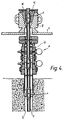
- each bore 2 is provided at the open upper end, below a working deck 5 of the derrick, with a safety and control valve system 6 as an assurance against gas and oil eruptions.
- This so-called piping head 6 is provided with a through passage 7 with cross-sections which are substantially smaller than the cross-section of the bore 2 itself.
- Above the working deck 5 is situated a housing 8 incorporating catching wedges 9 for guiding the casing string 3 into the bore 2.
- the passage cross-sections are small compared to the bore diameter in the rock.
- the centralizer 4 described above with reference to Figures 2 and 3 of the drawings passes readily through the housing 8 and through the piping head 6, because the spring strips 12 are held closely adjacent the surface of the casing string 3. This overcomes a problem of previous centralizers, where the spring strips are unstressed, and these must be forced through the housing 8 and the piping head 6.
- the casing string 3 is moved to a required position in the bore 2.
- the centralizer described above with reference to the drawings is held in the collapsed disposition until the associated casing is positioned in the borehole, there is no possibility of the centralizer snagging and preventing movement of the casing 11.
- the amount of bowing can be greater than with conventional centralizers, whose bowing is limited in order to reduce the possibility of snagging.
- the titanium link 15 is very secure during movement of the casing but parts very reliably on contact with hydrofluoric acid.
- centralizer 4 Referring next to Figures 9 and 10, a second form of centralizer 4 will now be described. Parts of the first and second forms of centralizer are common and thus bear the same reference numerals and will not be described in detail.
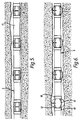
- the narrow band 14 is replaced by a band 17 which overlies the whole of the centralizer.
- This wider band could be of a fabric or a plastics material.
- it has the advantage that it can hold a greater spring force from the spring strips 12 and also can hold the spring strips 12 in a lower profile.
- the band 17 may be rectangular and be formed into a casing holding the spring strips 12 by a titanium wire stitched along the matching edges of the band 17. The wire is then reacted with hydrofluoric acid, as described above, when the casing 11 is positioned in a borehole as described above. This will allow the spring strips 12 to move to the deployed position shown in Figures 6 and 8 for engagement with the borehole, as described above.
- the band 14,17 need not be held by the use of titanium or released by the use of hydrofluoric acid.
- the band 14,17 could be held by some other material which can be reacted with a particular chemical to weaken the material and release the band when required.
- the band 14,17 could be held by some device which releases the band after a specified time or delay or by a device which is actuated to release the band 14,17, by electrical or magnetic means.
- centralizer In the third form of centralizer, four pairs of struts 18,19 are included, equally angularly spaced around the sleeves 10 intermediate the spring strips 12.
- the two struts 18,19 of each pair lie in a plane including the axis of the sleeves 10 and are pivotally connected together intermediate the sleeves 10.
- the ends opposite the pivotally connected ends, are themselves pivotally connected to an associated sleeve 10.
- struts 18,19 of each pair are aligned to one another close to an outer surface 16 of the casing 11. This causes the sleeves 10 to be moved to a maximum spacing which tends to hold the spring strips 12 in their collapsed disposition.
- a titanium sleeve 20 is slid over the pivotally connected ends of each pair of struts 18,19 to hold the struts in this disposition.
- the hydrofluoric acid also weakens the sleeve 20.
- This arrangement has the advantage that the struts 18,19 allow stronger spring strips 12 to be used than in the embodiments of Figures 2, 3, 10 and 11. They provide an additional force to keep the sleeves 10 at their maximum spacing.
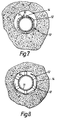
- the spring strips 12 when deployed, the struts can engage the surrounding borehole and provide an additional centralizing force. This is best seen in the cross-sectional view in Figure 12.
- each strut 21 is provided spaced equi-angularly around the sleeves intermediate the spring strips.
- Each strut 21 has one end fixed to a sleeve 25 which is not connected to the casing 11 and extends parallel to the axis of the sleeves 25 and through apertures 22 in a sleeve 26 which is fixed to the casing.
- An end of each strut 21 projecting beyond the fixed sleeve 26 is received in an energizing device 23.
- the band 17 is released as described above.
- the spring strips then move to a first deployed position which is shown in Figure 14. This results in the strut engaging in the energizing device, as seen in Figure 14.
- the energizing device 23 is then actuated to move along the casing 11 as shown in Figure 15 in a direction away from the fixed sleeve 26. This draws the movable sleeve 25 closer to the fixed sleeve 26 and so increases the bowing of the spring strips 12.
- the strut 21 and the fixed sleeve 26 may include a ratchet arrangement which prevents return movement of the strut 21.
- the energizing device 23 may be actuated in any convenient way.
- One such way is shown in Figure 17.
- the energizing device 23 is in communication with the interior of casing 11.
- a liquid under high pressure is passed through coiled tubing between two plugs 24.
- the plugs 24 are deployed to define a closed chamber in that section of the casing which communicates with the device 23.
- the chamber pressure is then increased with high pressure liquid from the coil and this liquid acuates the energizing device 23.
- the whole casing could be pressurized.
- the energizing device 23 may be operated by provision of projecting fins or similar members which are arranged in the annulus between the casing 11 and the borehole and which act to move the energizing device when the pressure of material in the annulus is increased.
- centralizers described above with reference to the drawings have four spring strips, it will be appreciated that they may be provided with more or less spring strips.
- all the forms of centralizer have spring strips extending between two sleeves, the embodiments of Figures 2, 3, 9 and 10 in particular, may include only one sleeve. In this case, the spring strips may, in their deployed disposition, simply extend at an angle away from the casing surface 16.
- the band 14 of the embodiment of Figures 2 and 3 need not be released using an acid, as described above with reference to those Figures.
- an acid as described above with reference to those Figures.
- a locking device is provided to control release of the band 14, in the form of a pressure element 30 comprising a piston 31, which is displaceably mounted in the cylindrical bore of the pressure element.
- the cylindrical bore is closed by means of a cover 33 which has a central opening 34 through which extends a pin 35 of the piston 31.
- a second cover 36 which may for example be secured via spacer screws, is placed at a distance from the cover 13.
- Two extremities 37a and 37b of the band 14 engage in the gap between the covers.
- One extremity, 37a is provided with an opening which is aligned with the central openings of the covers 33 and 36.
- the piston pin 35 extends through the opening as shown.
- the band extremity 37b is immovably joined to the cover 33.
- the releasable extremity 37a is located between two guide pins 38 extending between the covers 33 and 36. Openings 39 in the covers 33 and 36 provide communication between one piston side and the ambient pressure.
- the piston side facing away from the piston pin 35 is acted upon by the pressure of the gas present in the free cylinder space, for example air.
- the gas column forms a gas spring whose force is overcome when the ambient pressure exceeds a limiting value.
- the piston 31 is then pushed back under appropriate compression of the gas volume within the free cylinder space. In doing so, it draws the pin 35 out of the central openings and releases the extremity 37a of the band 14.
- the spring strips 12 of the centralizer 4 are then free to expand into contact with the surface surrounding the pipe, e.g. the rock.
- the pressure element 30 is provided with a mechanical spring 40 instead of an air cushion.
- the side of the piston 31 which faces away from the spring may be acted upon by pressure via a duct 41.
- the covers 33 and 36 lack the openings for communication with the ambient atmosphere.
- a third form of locking device is shown in Figure 20 and largely resembles that of Figure 19.
- the force of the mechanical spring 40 is controlled by means of a controllable gas pressure of a working fluid charge, for example a gas or liquid, present in a free space between one piston side and the element cover 33.
- the charge is heated by means of an electrical resistance, which is not illustrated, within the free space.
- the electrical power is supplied via a feed conductor 45.
- the gas in the free space expands or the liquid is initially converted into a gaseous state, both of which provide a large increase in volume and lead to the piston 31 being thrust back against the force of the mechanical spring 40.
- the piston 31 again withdraws the pin 35 from the releasable extremity 37a of the band 14 and so releases the band 14.
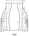
- FIG. 21 A variation of the embodiment of Figure 20 is shown in Figure 21 in which the mechanical spring 40 is situated at the piston side facing towards the element cover 33.
- the free space 46 present in the rearwardly situated section is filled with a fusible substance which may be placed in a fluid condition by means of a heating resistance supplied via the electrical lead 45.
- the material, when made fluid may leave the cylinder space of the element 30 via draining orifices 47.
- the force of the spring assures a displacement of the piston 11, so drawing the pin 45 out of the opening of the band 14.
- the melting or dissolution of the fusible substance may be induced by the supply of thermal energy by geothermal heat, which increases with the depth. It may equally be envisaged to feed in a solvent via a duct, so that the material present in the solid state in the free cylinder space may be dissolved by a chemical action. This also includes the possibility of dissolving the material during the bore flushing operation. A combination of several possibilities may also be contemplated to ensure release.
- Figures 23 and 24 show a possible variation of the embodiment of Figure 22 in which a traction element 60, for example a cable, has one end fastened to the piston rod 50 projecting out of the pressure element.
- the other end of the traction cable 60 is solidly joined to a ring 61 which fits immovably on the casing 11.
- the traction cable 60 is tensioned by rotation of the whole casing string to withdraw the piston pin 35 from the opening of the stressing element extremity 37a.
- the pressure element then resembles the embodiment according to Figure 22, the free space being occupied either by an air cushion acting as a piston spring, or else by a mechanical spring.
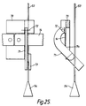
- FIG. 25 Another possible structure of the locking device is shown in Figure 25 in which both extremities of the band 4 are fixedly attached to a holding plate 70.
- a lever 71 is pivotally journalled on the holding plate 70 by means of a pivot pin 72.
- the lever 71 is constructed as a cutting tool appropriate for severing the band 4.
- a free end of the lever 71 carries a guiding element 73 for a traction cable 53 provided with a conical locking element 54 at its lower extremity. In use, the cone is drawn against the guiding element 73 when the cable 53 is pulled and transfers the tractive force to the lever 71, so that a cutting edge 71a of the cutting tool 71 severs the band 14 and releases the spring strips 12.
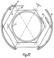
- Figures 26 and 27 show an alternative way of holding the spring strips 12 in a collapsed disposition using a band 14.
- the centralizer 4 comprises sleeves 10, Spring strips 12 extending between the sleeves 10 and a band 14.
- the spring strips 12 are indicated in the stressed state by a broken line and marked 12.
- Loops or eyes 80 are welded to the inward sides of the spring strips 12 and a straplike or cablelike band 14 is threaded through these loops or eyes 80. Since the eyes 80 are situated on the inward sides of the spring strips 12, their outer sides are not altered, so that no difficulties can be caused by sharp edges or corners.
- the centralizer 4 mounted on the casing 11 is drawn into an outer pipe, for example a lining pipe 81, and is placed in contact with its inward side by releasing the band 14 by operation of a locking device of any of the kinds described above with reference to the drawings.
- the casing 11 may thereby be held centrally in a conventional manner.
- each band extremity 37a, 37b is formed with two moulded parts 90,91 which together form two spaced chambers 92,93.
- One chamber 92 contains the positive half 94 of a battery.
- the other chamber 93 contains the negative half 95 of a battery.
- the extremities 37a, 37b of the bands 14 are held together by a wrap of material 96 of a thermoplastic or other heat-sensitive material.
- An electrically conductive wire 97 is connected at one end to the positive battery half 94 and passes through the wrap 96 to terminate at a magnet 98 located adjacent the negative battery half 95.
- the centralizer 4 is moved into a desired position as described above with reference to the drawings and an oil based mud containing iron filings is circulated through the casing string 3 and around the space between the casing string 3 and the borehole.
- an oil based mud containing iron filings is circulated through the casing string 3 and around the space between the casing string 3 and the borehole.
- the iron filings are attracted by the magnet 98 and form a conductive path 110 between the magnet and the negative half 95 of the battery. This completes the circuit and causes the conductive wire 97 to heat up in turn causing the wrap 97 to split.
- each band extremity is formed with a shaped part 99 with the two shaped parts 99 together cooperating to form a closed chamber 100.
- a membrane 101 divides the chamber 100 into two parts and each part contains a different chemical 102,103. The two chemicals are chosen such that, when they are mixed together, their volume increases rapidly.
- the membrane 101 holds a magnet 104 adjacent the radially outermost inner surface 105 of the chamber 100; the radial direction being measured relative to the axis of the casing 11 carrying the centralizer 4.
- a plug 106 is passed through the casing 11, as shown in Figure 32.
- the plug 106 carries a magnet 107 which, as it passes the closed chamber 100, attracts the chamber magnet 104. This breaks the membrane 101 so causing the two chemicals 102,103 to mix. This results in an increase in volume which separates the shaped parts 99 so releasing the band 14.
- the spring strips 12 thus move to the deployed position.
- the magnet 104 is held by the membrane 101 aligned in a radial direction relative to the axis of the associated casing 11. As the plug 106 is passed through the casing 11, the magnet 107 causes the chamber magnet 104 to rotate (see Figure 34) so breaking the membrane 101. The chemicals 102,103 then mix and expand as before, so releasing the band extremities 37a, 37b.
- the chamber magnet 104 is not moved by the plug. Rather, a wire line tool 108 is passed through the casing 11 which generates a strong magnetic field. This is sufficient to attract the chamber magnet 104 so breaking the membrane 101 and releasing the chemicals 102, 103, as before.
- the wire line tool 108 can also sense actuation of the chamber magnet 104 and release of the band 14, and can pass a corresponding signal to the surface.
- the ends of the band 14 could be held together by a pin which could be connected to wire leading to the top of the bore. Pulling on the wire would release the pin and allow the springs of the centralizer to expand against the side of the bore.
- the member 12 need not be a spring but could simply comprise a strip of metal which bowed outwardly against the side of the bore on movement of the energizing device 23.
- band 17 would not be necessary although a small outward bend in member 12 would be advantageous to facilitate bowing.
Landscapes
- Engineering & Computer Science (AREA)
- Geology (AREA)
- Life Sciences & Earth Sciences (AREA)
- Mining & Mineral Resources (AREA)
- Physics & Mathematics (AREA)
- Geochemistry & Mineralogy (AREA)
- Environmental & Geological Engineering (AREA)
- Fluid Mechanics (AREA)
- General Life Sciences & Earth Sciences (AREA)
- Chemical & Material Sciences (AREA)
- General Chemical & Material Sciences (AREA)
- Mechanical Engineering (AREA)
- Chemical Kinetics & Catalysis (AREA)
- Earth Drilling (AREA)
- Pipe Accessories (AREA)
- Lubricants (AREA)
- Consolidation Of Soil By Introduction Of Solidifying Substances Into Soil (AREA)
- Paper (AREA)
- Physical Deposition Of Substances That Are Components Of Semiconductor Devices (AREA)
Abstract
Description
- The invention relates to centralizers for oil well casings.
- As an oil well is drilled, the casings are lowered from a derrick in a string into the borehole so formed and drilling mud is circulated down the casing string, through the end of the final casing, back up through the annular space between the casing string and the borehole. At intervals, the casing string is cemented in position by pumping a suitable cement into the casing string which passes out of the final casing and into the annulus between the casing string and the borehole, displacing the mud, and which, when set, holds the casing string in position.
- It is important that all of the annular space between the casing string and the surrounding borehole is filled with cement and that the cement is firmly bonded to both the casing string and the borehole. In order to achieve this, it is important that all of the drilling mud is displaced from this space by the cement.
- The mud is unlikely to be replaced successfully if the casing string is not located centrally in the borehole.
- If the casing string is close to, or touching, the borehole then pockets may be formed where mud collects and is not displaced by the cement.
- Such centralization of the casing string is important where the borehole is vertical, but is even more important where the borehole is at an angle to the vertical, particularly where it is horizontal or nearly horizontal. This is because in such angled or horizontal boreholes gravity tends to drop the casing string on to the surrounding borehole.
- It has been usual to centralize the casing string by the use of centralizers. These have customarily been of two forms. A first form has a number of bowed springs arranged around a casing and connected to sleeves which are mounted on the casing. The portions of the springs remote from the casing surface engage the surrounding borehole to centralize the casing but do not impede substantially the flow of cement and mud. A second form comprises a one-piece sleeve which fits over the casing and is provided with angularly-spaced, longitudinally-extending ribs which engage the surrounding borehole with the passages formed between the ribs allowing flow of cement and mud.
- Though such centralizers have been used successfully for many years in vertical or near-vertical boreholes, they are less satisfactory when used in horizontal or near-horizontal boreholes. This is because to pass casing into such horizontal or near-horizontal boreholes requires the casing string to pass from a vertical section of the borehole to the horizontal or near-horizontal section around a corner and the projecting springs or ribs on the presently used centralizers can catch on such a corner and prevent or impede the passage of the casing.
- For this reason, it has become customary to use few, if any, centralizers in horizontal or near-horizontal boreholes. This can produce the cementing problems described above and can also produce problems should explosive perforation of the casing be required in such a borehole.
- US-A-2 490 350 discloses a centralizer for oil well casing which centralizer comprises an annular mounting by which the centralizer may be mounted on an outer surface of a casing and a plurality of members carried by the mounting at spaced positions therearound, wherein the members are held by a control device in a collapsed disposition in which the members extend along said casing closely adjacent said outer surface of the casing, said control device being remotely operable so that the members move from said collapsed disposition to a deployed disposition in which the members extend away from said mounting for engagement with an associated borehole.
- Thus, by holding the members in a collapsed disposition until the centralizer and the associated casing string has been deployed, the members do not impede the passage of the casing string into and through the borehole.
- The disadvantage of this arrangement is that the control device passes through the wall of the casing thus creating a localised area of low bursting strength.
- A similar problem arises in US-A-4 523 640 where the bows of a well tool are inhibited from radial expansion by a collar which is secured to a tube by a meltable shear pin which extends through the collar into a bore tapped in the pipe.
- In US-A-2 656 890 the springbows of a centralizer are held in a collapsed position by a collar which is pushed down the wellbore by the springbows. The casing is lowered until it reaches a position a little below its desired position. It is then raised. Prongs on the collar hopefully engage the wellbore so that the collar remains stationary whilst the springbows rise, this relative movement releasing the springbows. Engagement of the prongs with the wellbore is not reliable and consequently release of the springbows cannot be guaranteed therefore making this arrangement generally unsatisfactory.
- The present invention is characterized in that the control device is positionable wholly radially outwardly or wholly radially inwardly of said casing and is remotely operable after said casing has been located in its desired position to deploy said members.
- The following is a more detailed description of some embodiments of the invention, by way of example, reference being made to the accompanying drawings in which:-
- Figure 1 is a schematic view of an oil well showing a casing string extending from a derrick to a deposit, with the casing string extending from the derrick in a vertical direction and then extending in an almost horizontal direction.
- Figure 2 is a side elevation, partly in section, and a cross-sectional end view, of a portion of a casing of an oil well showing a first form of centralizer in a collapsed disposition.
- Figure 3 is a similar view to Figure 2, but showing the centralizer in a deployed position,
- Figure 4 is a schematic cross-section of an upper end of the oil well of Figure 1 showing a piping head below a working deck of the derrick and a housing above the working deck and showing a casing string carrying centralizers of the kind shown in Figures 2 and 3 passing into the bore via the housing and piping head,
- Figure 5 shows the centralizer of Figures 2 and 3 on a casing within a borehole and in a collapsed disposition, and
- Figure 6 is a similar view to Figure 5 but with the centralizer deployed,
- Figure 7 is a cross-sectional view of the centralizer of Figures 2 and 3 on a casing within a borehole and in a collapsed disposition,
- Figure 8 is a cross-sectional view of the centralizer of Figures 2 and 3 on a casing with a borehole and in a deployed disposition,
- Figure 9 is a similar view to Figures 2 and 3, but showing the second form of centralizer in a collapsed disposition,
- Figure 10 is a similar view to Figure 9 but showing a second form of centralizer in a deployed, disposition,
- Figure 11 is a similar view to Figures 2, 3, 9 and 10 but showing a third form of centralizer in a collapsed disposition in both cross-section and side elevation,
- Figure 12 is a similar view to Figure 11 but showing a third form of centralizer in a deployed disposition in both cross-section and side elevation and showing a detail of a holding sleeve positioning a pair of struts of the centralizer device.
- Figure 13 is a similar view to Figures 9 and 10 but showing a fourth form of centralizer in a collapsed disposition in both cross-section and side elevation,
- Figure 14 is a similar view to Figure 13 but showing the fourth form of centralizer in a first deployed position ub both cross-section and side elevation,
- Figure 15 is a similar view to Figures 9 and 10 but showing the fourth form of centralizer in a second deployed position in both cross-section and side elevation,
- Figure 16 is a section through a horizontal borehole showing the fourth form of centralizer in the second deployed position of Figure 15,
- Figure 17 is a similar view to Figure 15 but showing an alternative mode of energizing the fourth form of centralizer,
- Figure 18 is a plan view and a cross-section of a locking device for holding and releasing a band of a centralizer of the kind shown in Figures 2 and 3, the locking device comprising a pressure element including an air cushion within the free cylinder space,
- Figure 19 is a plan view and a cross-section of a pressure element similar to that shown in Figure 18 comprising a piston prestressed by means of a mechanical spring and a duct which is in communication with the free piston space at a piston side facing away from the prestressing spring,
- Figure 20 is a further embodiment of the pressure element of the kind shown in Figures 18 and 19 comprising a heating line which leads into a free space at a side of the piston facing towards a spring,
- Figure 21 is a plan view and a cross-section of an alternative embodiment of a pressure element of the kind shown in Figures 18 to 20 in which a free space is filled with a material which is solid but fusible by means of heating resistances,
- Figure 22 is a plan view and a cross-section of an additional form of pressure element of the kind shown in Figures 18 to 20 comprising a mechanical lever system for releasing a piston pin from an opening of an extremity on a band,
- Figure 23 is a cross-sectional view of a borehole showing a system for releasing a locking device for a band which may be operated by rotation of the casing string,
- Figure 24 shows the system according to Figure 23 with a band released and and spring strips unstressed,
- Figure 25 is a locking device in the form of a securing plate to which is fastened a cutting tool fastened for operation by a traction element,
- Figure 26 is a cross-sectional view of a part of a casing string carrying a centralizer and partially inserted in a lining,
- Figure 27 is a cross-section through the centralizer of Figure 26,
- Figure 28 is a schematic cross-sectional view of the ends of a band of a centralizer of the kind shown in Figures 2 and 3 showing a battery and fuse wire system for release of the band,
- Figure 29 is a similar view to Figure 28 but showing the release of the band,
- Figure 30 is a similar view to Figures 28 and 29 showing the band released,
- Figure 31 is a schematic cross-sectional view of the ends of a band of a centralizer of the kind shown in Figure 2 and 3, showing magnetic actuation and chemical release of the band,
- Figure 32 is a similar view to Figure 31 showing the magnetic actuation,
- Figure 33 is a schematic cross-sectional view of the ends of a band of a centralizer of the kind shown in Figures 2 and 3 showing a further mode of release by magnetic actuation and chemical release of the band,
- Figure 34 is a similar view to Figure 33 showing the release,
- Figure 35 is a schematic cross-sectional view of the ends of a band of a centralizer of the kind shown in Figures 2 and 3 with wire line actuation and chemical release of the band, and
- Figure 36 shows the release of the band.
- The casing centralizers now to be described with reference to the drawings can be utilized in in oil well of the kind shown in Figure 1. As shown in Figure 1, oil bearing deposits are reached from a
drilling derrick 1, and are not only located at great depths but also at a position horizontally spaced from the derrick location. Thebore 2 as a whole consequently forms in arc merging from the vertical into the horizontal through, the rock, and thisbore 2 has to be followed by acasing string 3 comprisingindividual casings 11. The force with which the pipeline bears on the bore sides creates considerable frictional forces, especially in the case of a horizontal run, which may damage the casing string. For this reason, thecasing string 3 is protected against contact with the rock by means of centralizers 4 of the kinds to be described below. - Referring first to Figures 2 and 3, the first form of centralizer comprises a pair of
metal sleeves 10 whose interior diameter is substantially equal to the exterior diameter of acasing 11 of a casing string for an oil well borehole. A typical casing diameter may be 125 mm. - Four spring strips 12 are connected between the sleeves and spaced equi-angularly around the
sleeves 10. Each spring strip has a bowed unstressed profile as shown in Figure 3 and is provided intermediate its ends with achannel 13. - In use, the
sleeves 10 are located on acasing 11 by spanning a joint betweencasings 11 between a stop collar (not shown) such that the sleeves can slide on the casing to a limited degree. Aband 14 is placed around the spring strips 12 in thechannels 13 and is tightened to draw the spring, strips 12 against the outer surface of thecasing 11, as seen in Figure 2. This moves thesleeves 10 to a maximum spacing. - The
band 14 is held tight by atitanium link 15. - The
casings 11 is then inserted in the casing string 3 (Figure 1) in anoil well bore 2. This is achieved in the following way both in the embodiment described above with reference to Figures 2 and 3, but also in the subsequently described embodiments. - Referring to Figure 4, each bore 2 is provided at the open upper end, below a working
deck 5 of the derrick, with a safety and control valve system 6 as an assurance against gas and oil eruptions. This so-called piping head 6 is provided with a through passage 7 with cross-sections which are substantially smaller than the cross-section of thebore 2 itself. Above the workingdeck 5 is situated a housing 8 incorporating catchingwedges 9 for guiding thecasing string 3 into thebore 2. In the housing 8 too, the passage cross-sections are small compared to the bore diameter in the rock. - The centralizer 4 described above with reference to Figures 2 and 3 of the drawings passes readily through the housing 8 and through the piping head 6, because the spring strips 12 are held closely adjacent the surface of the
casing string 3. This overcomes a problem of previous centralizers, where the spring strips are unstressed, and these must be forced through the housing 8 and the piping head 6. Thecasing string 3 is moved to a required position in thebore 2. - The circulation of mud is then halted and hydrofluoric acid is passed through the casing and into the annulus between the casing and the borehole. The titanium of the
link 15 reacts with the hydrofluoric acid and softens to an extent that the ends of the bands separate under the spring biasing force of the spring strips 12 to release the band. The spring strips thus bow to their unstressed position shown in Figure 3 and thesleeves 10 approach each other by sliding along theouter surface 16 of thecasing 11. - Thus, as seen in the cross-sectional view of Figure 3, four bowed string strips 12 project from the outer surface of the
casing 11. As will be seen in Figures 6 and 8 these spring strips 12 hold thecasing 11 central in the borehole. - Since the centralizer described above with reference to the drawings is held in the collapsed disposition until the associated casing is positioned in the borehole, there is no possibility of the centralizer snagging and preventing movement of the
casing 11. The amount of bowing can be greater than with conventional centralizers, whose bowing is limited in order to reduce the possibility of snagging. Thetitanium link 15 is very secure during movement of the casing but parts very reliably on contact with hydrofluoric acid. - Referring next to Figures 9 and 10, a second form of centralizer 4 will now be described. Parts of the first and second forms of centralizer are common and thus bear the same reference numerals and will not be described in detail.
- In the second centralizer, the
narrow band 14 is replaced by aband 17 which overlies the whole of the centralizer. This wider band could be of a fabric or a plastics material. In comparison with thenarrow band 14 of Figure 1, it has the advantage that it can hold a greater spring force from the spring strips 12 and also can hold the spring strips 12 in a lower profile. - The
band 17 may be rectangular and be formed into a casing holding the spring strips 12 by a titanium wire stitched along the matching edges of theband 17. The wire is then reacted with hydrofluoric acid, as described above, when thecasing 11 is positioned in a borehole as described above. This will allow the spring strips 12 to move to the deployed position shown in Figures 6 and 8 for engagement with the borehole, as described above. - It will be appreciated that, in either of the embodiments described above, the
band band band band - Referring next to Figures 11 and 12, the third form of centralizer has parts common to the second form shown in Figures 9 and 10. Accordingly, those parts will not be described in detail and will be given the same reference numerals.
- In the third form of centralizer, four pairs of
struts sleeves 10 intermediate the spring strips 12. The two struts 18,19 of each pair lie in a plane including the axis of thesleeves 10 and are pivotally connected together intermediate thesleeves 10. The ends opposite the pivotally connected ends, are themselves pivotally connected to an associatedsleeve 10. - In a collapsed disposition, the
struts outer surface 16 of thecasing 11. This causes thesleeves 10 to be moved to a maximum spacing which tends to hold the spring strips 12 in their collapsed disposition. In this position, as seen in the detail in Figure 12, atitanium sleeve 20 is slid over the pivotally connected ends of each pair ofstruts - When the
band 17 is released by passing hydrofluoric acid around the centralizer, the hydrofluoric acid also weakens thesleeve 20. This allows thestruts sleeves 10 to be decreased. This arrangement has the advantage that thestruts sleeves 10 at their maximum spacing. In addition, when the spring strips 12 are deployed, the struts can engage the surrounding borehole and provide an additional centralizing force. This is best seen in the cross-sectional view in Figure 12. - It will be appreciated, of course, that in this third form the sleeve may be omitted and the struts used alone to control the spring strips 12.
- Referring next to Figures 13, 14 and 15, the fourth form of centralizer 4 shown in those figures has features common to the second embodiment, of Figures 9 and 10. Those features will not be described in detail and will be given the same reference numerals.
- In the fourth form of centralizer 4, four
struts 21 are provided spaced equi-angularly around the sleeves intermediate the spring strips. Eachstrut 21 has one end fixed to asleeve 25 which is not connected to thecasing 11 and extends parallel to the axis of thesleeves 25 and throughapertures 22 in asleeve 26 which is fixed to the casing. An end of eachstrut 21 projecting beyond the fixedsleeve 26 is received in an energizingdevice 23. - In use, the
band 17 is released as described above. The spring strips then move to a first deployed position which is shown in Figure 14. This results in the strut engaging in the energizing device, as seen in Figure 14. - The energizing
device 23 is then actuated to move along thecasing 11 as shown in Figure 15 in a direction away from the fixedsleeve 26. This draws themovable sleeve 25 closer to the fixedsleeve 26 and so increases the bowing of the spring strips 12. - The
strut 21 and the fixedsleeve 26 may include a ratchet arrangement which prevents return movement of thestrut 21. - This additional bowing movement of the spring strips 12 allows the strips to engage more firmly with the borehole, as shown in Figure 16. This allows the centralizer 4 to accommodate irregularities or portions of the borehole which have widened due to formation collapse or wash out.
- The energizing
device 23 may be actuated in any convenient way. One such way is shown in Figure 17. In this arrangement, the energizingdevice 23 is in communication with the interior ofcasing 11. A liquid under high pressure is passed through coiled tubing between two plugs 24. At an energizer, theplugs 24 are deployed to define a closed chamber in that section of the casing which communicates with thedevice 23. The chamber pressure is then increased with high pressure liquid from the coil and this liquid acuates the energizingdevice 23. - Alternatively, the whole casing could be pressurized.
- It will also be appreciated that the energizing
device 23 may be operated by provision of projecting fins or similar members which are arranged in the annulus between thecasing 11 and the borehole and which act to move the energizing device when the pressure of material in the annulus is increased. - Although the centralizers described above with reference to the drawings have four spring strips, it will be appreciated that they may be provided with more or less spring strips. In addition, although all the forms of centralizer have spring strips extending between two sleeves, the embodiments of Figures 2, 3, 9 and 10 in particular, may include only one sleeve. In this case, the spring strips may, in their deployed disposition, simply extend at an angle away from the
casing surface 16. - As suggested above, the
band 14 of the embodiment of Figures 2 and 3 need not be released using an acid, as described above with reference to those Figures. There will now be described some alternative ways of releasing theband 14, parts common to Figures 2 and 3, and to the Figures now to be described having the same reference numerals and not being described in detail. - Referring first to Figure 18, a locking device is provided to control release of the
band 14, in the form of apressure element 30 comprising apiston 31, which is displaceably mounted in the cylindrical bore of the pressure element. The cylindrical bore is closed by means of acover 33 which has acentral opening 34 through which extends apin 35 of thepiston 31. Asecond cover 36, which may for example be secured via spacer screws, is placed at a distance from thecover 13. - Two
extremities band 14 engage in the gap between the covers. One extremity, 37a, is provided with an opening which is aligned with the central openings of thecovers piston pin 35 extends through the opening as shown. Theband extremity 37b is immovably joined to thecover 33. Thereleasable extremity 37a is located between two guide pins 38 extending between thecovers Openings 39 in thecovers - In use, the piston side facing away from the
piston pin 35 is acted upon by the pressure of the gas present in the free cylinder space, for example air. The gas column forms a gas spring whose force is overcome when the ambient pressure exceeds a limiting value. Thepiston 31 is then pushed back under appropriate compression of the gas volume within the free cylinder space. In doing so, it draws thepin 35 out of the central openings and releases theextremity 37a of theband 14. The spring strips 12 of the centralizer 4 are then free to expand into contact with the surface surrounding the pipe, e.g. the rock. - In a second form of the locking device shown in Figure 19, the
pressure element 30 is provided with amechanical spring 40 instead of an air cushion. The side of thepiston 31 which faces away from the spring may be acted upon by pressure via aduct 41. In this case thecovers - A third form of locking device is shown in Figure 20 and largely resembles that of Figure 19. The force of the
mechanical spring 40 is controlled by means of a controllable gas pressure of a working fluid charge, for example a gas or liquid, present in a free space between one piston side and theelement cover 33. The charge is heated by means of an electrical resistance, which is not illustrated, within the free space. The electrical power is supplied via afeed conductor 45. As the temperature rises, the gas in the free space expands or the liquid is initially converted into a gaseous state, both of which provide a large increase in volume and lead to thepiston 31 being thrust back against the force of themechanical spring 40. Thepiston 31 again withdraws thepin 35 from thereleasable extremity 37a of theband 14 and so releases theband 14. - A variation of the embodiment of Figure 20 is shown in Figure 21 in which the
mechanical spring 40 is situated at the piston side facing towards theelement cover 33. Thefree space 46 present in the rearwardly situated section is filled with a fusible substance which may be placed in a fluid condition by means of a heating resistance supplied via theelectrical lead 45. The material, when made fluid, may leave the cylinder space of theelement 30 via drainingorifices 47. The force of the spring assures a displacement of thepiston 11, so drawing thepin 45 out of the opening of theband 14. - In an alternative form of release of the
band 14, the melting or dissolution of the fusible substance may be induced by the supply of thermal energy by geothermal heat, which increases with the depth. It may equally be envisaged to feed in a solvent via a duct, so that the material present in the solid state in the free cylinder space may be dissolved by a chemical action. This also includes the possibility of dissolving the material during the bore flushing operation. A combination of several possibilities may also be contemplated to ensure release. - In a further alternative version of the locking device of Figures 18 to 21, shown in Figure 22, the force of the
piston 31 which is generated by means of a gas pressure within the free cylinder space, is cancelled by means of a mechanical lever system situated outside the pressure element. To this end, the piston is provided with apiston rod 50 extending outwards through the cylinder base. Alever 51 is pivotally connected to thepiston rod 50. A power arm of thelever 51 is looped to embrace an end of atraction element 53 having a widened terminal part in the form of acone 54. The other arm of thelever 51 is supported on the outer side of thepressure element 30. By a pull on theelement 53 in the direction of the arrow 55, thecone 54 is drawn into contact with the looped arm section of thelever 51 and thus transfers its tractive force to thelever 51. Thelever 51 pivots and draws thepiston pin 35 out of the opening of the stressingelement extremity 37a so releasing the band. - Figures 23 and 24 show a possible variation of the embodiment of Figure 22 in which a
traction element 60, for example a cable, has one end fastened to thepiston rod 50 projecting out of the pressure element. The other end of thetraction cable 60 is solidly joined to a ring 61 which fits immovably on thecasing 11. Thetraction cable 60 is tensioned by rotation of the whole casing string to withdraw thepiston pin 35 from the opening of the stressingelement extremity 37a. The pressure element then resembles the embodiment according to Figure 22, the free space being occupied either by an air cushion acting as a piston spring, or else by a mechanical spring. - Another possible structure of the locking device is shown in Figure 25 in which both extremities of the band 4 are fixedly attached to a holding
plate 70. Alever 71 is pivotally journalled on the holdingplate 70 by means of apivot pin 72. Thelever 71 is constructed as a cutting tool appropriate for severing the band 4. A free end of thelever 71 carries a guidingelement 73 for atraction cable 53 provided with aconical locking element 54 at its lower extremity. In use, the cone is drawn against the guidingelement 73 when thecable 53 is pulled and transfers the tractive force to thelever 71, so that acutting edge 71a of thecutting tool 71 severs theband 14 and releases the spring strips 12. - Figures 26 and 27 show an alternative way of holding the spring strips 12 in a collapsed disposition using a
band 14. In this arrangement the centralizer 4 comprisessleeves 10, Spring strips 12 extending between thesleeves 10 and aband 14. The spring strips 12 are indicated in the stressed state by a broken line and marked 12. Loops oreyes 80 are welded to the inward sides of the spring strips 12 and a straplike orcablelike band 14 is threaded through these loops oreyes 80. Since theeyes 80 are situated on the inward sides of the spring strips 12, their outer sides are not altered, so that no difficulties can be caused by sharp edges or corners. In the example depicted, the centralizer 4 mounted on thecasing 11 is drawn into an outer pipe, for example alining pipe 81, and is placed in contact with its inward side by releasing theband 14 by operation of a locking device of any of the kinds described above with reference to the drawings. Thecasing 11 may thereby be held centrally in a conventional manner. - Referring now to Figures 28 to 30, these illustrate an alternative means of releasing the
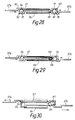
extremities band 14 of the kind described above with reference to Figures 2 and 3. In this case, eachband extremity parts chambers chamber 92 contains thepositive half 94 of a battery. Theother chamber 93 contains thenegative half 95 of a battery. - The
extremities bands 14 are held together by a wrap ofmaterial 96 of a thermoplastic or other heat-sensitive material. An electricallyconductive wire 97 is connected at one end to thepositive battery half 94 and passes through thewrap 96 to terminate at amagnet 98 located adjacent thenegative battery half 95. - In operation, the centralizer 4 is moved into a desired position as described above with reference to the drawings and an oil based mud containing iron filings is circulated through the
casing string 3 and around the space between thecasing string 3 and the borehole. As seen in Figure 29, the iron filings are attracted by themagnet 98 and form aconductive path 110 between the magnet and thenegative half 95 of the battery. This completes the circuit and causes theconductive wire 97 to heat up in turn causing thewrap 97 to split. - Thus, as seen in Figure 30, the two
band extremities - A further mode of separating the
band extremities shaped part 99 with the two shapedparts 99 together cooperating to form aclosed chamber 100. Amembrane 101 divides thechamber 100 into two parts and each part contains a different chemical 102,103. The two chemicals are chosen such that, when they are mixed together, their volume increases rapidly. - The
membrane 101 holds amagnet 104 adjacent the radially outermostinner surface 105 of thechamber 100; the radial direction being measured relative to the axis of thecasing 11 carrying the centralizer 4. - In use, a
plug 106 is passed through thecasing 11, as shown in Figure 32. Theplug 106 carries amagnet 107 which, as it passes theclosed chamber 100, attracts thechamber magnet 104. This breaks themembrane 101 so causing the two chemicals 102,103 to mix. This results in an increase in volume which separates the shapedparts 99 so releasing theband 14. The spring strips 12 thus move to the deployed position. - Referring next to Figures 33 and 34, the arrangement shown in these Figures is similar to that shown in Figures 31 and 32 and so parts common to these two embodiments will be given the same reference numerals and will not be described in detail. In this embodiment, the
magnet 104 is held by themembrane 101 aligned in a radial direction relative to the axis of the associatedcasing 11. As theplug 106 is passed through thecasing 11, themagnet 107 causes thechamber magnet 104 to rotate (see Figure 34) so breaking themembrane 101. The chemicals 102,103 then mix and expand as before, so releasing theband extremities - Finally, referring to Figures 35 and 36, the arrangement of these Figures has parts in common with the arrangement of Figures 31 and 32. Again, parts common to these Figures will be given the same reference numerals and will not be described in detail.
- In this embodiment, the
chamber magnet 104 is not moved by the plug. Rather, awire line tool 108 is passed through thecasing 11 which generates a strong magnetic field. This is sufficient to attract thechamber magnet 104 so breaking themembrane 101 and releasing thechemicals wire line tool 108 can also sense actuation of thechamber magnet 104 and release of theband 14, and can pass a corresponding signal to the surface. - In a very simple embodiment the ends of the
band 14 could be held together by a pin which could be connected to wire leading to the top of the bore. Pulling on the wire would release the pin and allow the springs of the centralizer to expand against the side of the bore. - It will be appreciated that in, for example the embodiment shown in Figures 13 to 17, the
member 12 need not be a spring but could simply comprise a strip of metal which bowed outwardly against the side of the bore on movement of the energizingdevice 23. In such anembodiment band 17 would not be necessary although a small outward bend inmember 12 would be advantageous to facilitate bowing.
Claims (32)
- A centralizer for well casings said centralizer comprising a mounting (10) by which the centralizer (4) may be mounted on an outer surface of a casing (11) and a plurality of members (12) carried by the mounting (10) at spaced positions therearound, wherein the members (12) are held by a control device (15 Fig. 2; 17 Fig. 9; 26 Fig. 13; 30 Fig. 18) in a collapsed disposition in which the members (12) extend along said casing (11) closely adjacent said outer surface thereof, said control device (15 Fig. 2; 17 Fig. 9; 26 Fig. 13; 30 Fig. 18) being remotely operable so that the members (12) move from said collapsed disposition to a deployed position in which the members (12) extend away from said mounting (10) for engagement with an associated borehole characterized in that said control device is positionable wholly radially outwardly or wholly radially inwardly of said casing and is remotely operable after said casing has been located in its desired position to deploy said members (12).
- A centralizer according to Claim 1, characterized in that each member (12) is resiliently biased towards said deployed disposition, the control device (15 Fig. 2; 17 Fig. 9; 26 Fig. 13; 30 Fig. 18) holding the members (12) in said collapsed disposition against said bias.
- A centralizer according to Claim 2, characterized in that each member comprises a spring strip (12) whose inherent resilience provides said bias.
- A centralizer according to claim 3 characterized in that the mounting includes two spaced annular sleeves (10), the ends of each spring strip (12) being connected to respective sleeves so that, in said deployed disposition, the spring strips (12) bow outwardly between said sleeves.
- A centralizer according to claim 3 or claim 4 characterized in that the control device comprises a band (14 Fig.2; 17 Fig.9) extending around said spring strips (12) and holding said spring strips (12) in said collapsed disposition against said resilient bias, said band (14 Fig.2; 17 Fig.9) being releasable to allow movement of said spring strips (12) to said deployed disposition.
- A centralizer according to claim 5 characterized in that the band (14 Fig.2; 17 Fig.9) is held by a part (15) which is chemically degradable to release said band.
- A centralizer according to any one of claims 3 to 6 wherein the control deice comprises at least one pair of struts (18,19) which are hinged together and which, at the ends opposite said hinged connection are pivotally connected to respective sleeves (10), the struts (18,19) being releasably held in a disposition in which the spacing between said sleeves (10) is a maximum to maintain said spring strips (12) in said collapsed disposition, release of said struts (18,19) causing said struts (18,19) to pivot as the spring strips (12) move to said deployed disposition and to cause the spacing of the sleeves (10) to decrease from said maximum.
- A centralizer according to claim 7 characterized in that the struts (18,19) are held by a part (20) which is chemically degradable to release said struts.
- A centralizer according to claim 6 or claim 8 characterized in that the part (15) is of titanium with said chemical being hydrofluoric acid.
- A centralizer according to any one of claims 7 to 9 characterized in that a pair of struts (18,19) is provided for each spring strip (12).
- A centralizer according to any one of claims 3 to 10 characterized in that the resilient bias of the spring strips (12) moves said spring strips (12) to a first deployed position in which said spring strips (12) have a first spacing from the associated casing outer surface, an energizing device (23) being provided to move said spring strips (12) to a second deployed position in which said spacing is increased.
- A centralizer according to claim 11 characterized in that two sleeves (25,26), are provided with the spring strips (12) extending between said sleeves (25,26), one sleeve (25) being attached to an associated casing (11) with the other sleeve (26) being unattached, a strut (21) being connected at one end to said other sleeve (26) and engaging, towards an end opposite said one end, said energizer device (23), the energizer device (23) being operable when the spring strips (12) are in the first deployed position to move the strut (21) to cause the other sleeve (26) to move closer to the first sleeve (25) so causing increased bowing of the spring strips (12) to said second deployed position.
- A centralizer according to claim 12 characterized in that the energizer device comprises a hydraulic device (23) in communication with the interior or an associated casing (11) and operated by high pressure fluid from the interior of the casing (11).
- A centralizer according to claim 5 characterized in that the band (14) is guided around the centralizer (4) on the inward sides of the spring strips (12) and that extremities (37a,37b) of the band (14) are held by a locking device (30,33,35) to hold the spring strips (12) in the collapsed disposition, the extremities (37a,37b) being releasable from the locking device at a predetermined point within the borehole to allow the spring strips (12) to adopt the deployed disposition.
- A centralizer according to claim 14 characterized in that guiding elements (80) for holding and guiding the band (14) are situated on the inward side of the spring strips (12).
- A centralizer according to claim 14 or claim 15 characterized in that the locking device comprises a pressure element (30) with a piston (31) housed therein having a pin (35) releasably engaged in an opening (34) of one of the band extremities (37a) , the piston (31) being normally in an operative position in which the pin (35) engages the band extremity (37a) and being movable from said operative position to release the pin (35) from the band extremity (37a) and so release the band (14).
- A centralizer according to claim 16 characterized in that the pressure element (30) comprises a cylindrical casing carrying a cover (33) having a central opening through which the piston pin (35) projects outwards and into the opening of an extremity (37a) of the band (14), the extremities (37a,37b) of the band (14) being located between the element cover (33) and a holding plate (36) which is fastened on the element cover and which is provided with a central opening for reception of the piston pin (35).
- A centralizer according to claim 16 or claim 17 characterized in that the pressure element (30) is provided with openings (39) to allow ambient atmosphere to act on one side of the piston (31) to move the piston (31) from the operative position.
- A centralizer according to claim 16 or claim 17 characterized in that the piston (31) is biased into said operative position by means of a pressurized gas.
- A centralizer according to claim 16 or claim 17 characterized in that the piston (31) is biased into said operative position by means of a mechanical spring (40).
- A centralizer according to claim 20 characterized in that the pressure element is connected to a control pressure duct (41) for providing fluid under pressure to the piston side facing away from the piston spring (40) to move the piston (31) from the operative position.
- A centralizer according to claim 19 or claim 20 characterized in that the pressure element is provided with a heating resistance (45) to control the temperature of a working fluid present therein, heating of the fluid moving the piston (31) from said operative position.
- A centralizer according to claim 19 or claim 20 characterized in that the pressure element is provided with outlet openings (47) and includes a working substance of solid consistency, which may be liquefied at will and removed via the drain holes (27), liquefaction of the working substance moving the piston (31) from the operative position.
- A centralizer according to claim 20 characterized in that the piston (31) is movable to said inoperative position against the force of the spring (40) by means of a lever mechanism.
- A centralizer according to claim 24 characterized in that the piston (31) is provided with a piston rod (50) which extends outwards through a central opening of the pressure element (30) and is movably coupled with a lever (51) supported on a rear wall of the element (30), a free end of the lever (51) being acted upon by a traction element (53) operable from the surface.
- A centralizer according to claim 25 characterized in that the traction element (53) extends through a loop formed at said free end of the lever (51), an end of the element (53) carrying a shaped member (54) which, on operation of the traction element (53) engages the loop to pivot the lever (51) and move the piston (31) from the operative position.
- A centralizer according to claim 14 or claim 15 characterized in that the locking device is provided with a parting tool for releasing the band (14).
- A centralizer according to claim 27 characterized in that the extremities (37a,37b) of the band (14) are fixedly joined to a plate (70) which carries a pivotable cutting tool (71) provided with a traction element (73) for operating the cutting tool (71) to cut the band (145) and so release the spring strips (12).
- A centralizer according to claim 16 characterized in that the piston (31) is provided with a piston rod extending outwards through a central opening of the element (30), to which is attached one end of a traction cable (60), the other end of the traction cable (60) being fixedly joined to a fastening ring (61) installed on a casting (11) carrying the centralizer (4) so that relative rotation of the centralizer (4) and the casing (11) moves the piston (31) from the operative position.
- A centralizer according to claim 5 characterized in that extremities (37a,37b) of the band (14) are held together by a wrap (96) to maintain the spring strips (12) in the collapsed disposition, a conductive wire (97) extending through the wrap and being connected at one end to one part (94) of an electrical battery, the other end of the wire (97) being connected to a magnet (98) located adjacent a terminal of the other part (95) of the battery, the passage of a fluid containing magnetic conductive particles past the band (14) causing said particles to be attached to the magnet (98) to form a conductive path between the wire (97) and the other battery part (98) so causing the conductive wire (97) to heat the wire and separate the wrap (96) so allowing the spring strips (12) to move to the deployed disposition.
- A centralizer according to claim 5 characterized in that the band (14) has two extremities (37a,37b), each extremity being associated with a respective chamber part (99) which co-operate together to form a closed chamber (100), the chamber (100) being divided by a membrane (101) with one division containing a first substance and the other division containing a second substance, means (104) being provided which are operable to break the membrane (101) so allowing the substance to mix, the substances being such that, on mixing, the volume thereof increases so separating the chamber parts (99) and allowing the spring strips (12) to move to the deployed position.
- A centralizer according to Claim 31, wherein said means is a magnet (104) carried by the membrane, the membrane (101) being broken by movement of the magnet (104) under the action of an applied magnetic force.
Applications Claiming Priority (5)
| Application Number | Priority Date | Filing Date | Title |
|---|---|---|---|
| GB909001007A GB9001007D0 (en) | 1990-01-17 | 1990-01-17 | Centralizers for oil well casings |
| GB9001007 | 1990-01-17 | ||
| DE4024000 | 1990-07-28 | ||
| DE19904024000 DE4024000C2 (en) | 1990-07-28 | 1990-07-28 | Pipe centering basket with clamping device |
| PCT/GB1991/000065 WO1991010806A1 (en) | 1990-01-17 | 1991-01-17 | Centralizers for oil well casings |
Publications (2)
| Publication Number | Publication Date |
|---|---|
| EP0511254A1 EP0511254A1 (en) | 1992-11-04 |
| EP0511254B1 true EP0511254B1 (en) | 1995-03-01 |
Family
ID=25895437
Family Applications (1)
| Application Number | Title | Priority Date | Filing Date |
|---|---|---|---|
| EP91902218A Expired - Lifetime EP0511254B1 (en) | 1990-01-17 | 1991-01-17 | Centralizers for oil well casings |
Country Status (7)
| Country | Link |
|---|---|
| US (1) | US5261488A (en) |
| EP (1) | EP0511254B1 (en) |
| AT (1) | ATE119234T1 (en) |
| CA (1) | CA2073332C (en) |
| DE (1) | DE69107833T2 (en) |
| NO (1) | NO305256B1 (en) |
| WO (1) | WO1991010806A1 (en) |
Families Citing this family (77)
| Publication number | Priority date | Publication date | Assignee | Title |
|---|---|---|---|---|
| US5097905A (en) * | 1991-01-28 | 1992-03-24 | Mobil Oil Corporation | Centralizer for well casing |
| US5411049A (en) * | 1994-03-18 | 1995-05-02 | Weatherford U.S., Inc. | Valve |
| US5680902A (en) * | 1994-03-22 | 1997-10-28 | Weatherford/Lamb, Inc. | Wellbore valve |
| GB9405679D0 (en) * | 1994-03-22 | 1994-05-11 | Weatherford Lamb | Fill valve |
| US5836395A (en) * | 1994-08-01 | 1998-11-17 | Weatherford/Lamb, Inc. | Valve for wellbore use |
| US5909771A (en) * | 1994-03-22 | 1999-06-08 | Weatherford/Lamb, Inc. | Wellbore valve |
| GB9419313D0 (en) * | 1994-09-24 | 1994-11-09 | Weatherford Lamb | Centralisers |
| GB9425240D0 (en) * | 1994-12-14 | 1995-02-08 | Head Philip | Dissoluable metal to metal seal |
| GB2299598B (en) * | 1995-04-07 | 1999-03-17 | Weatherford Lamb | Apparatus for use in a wellbore |
| US5575333A (en) * | 1995-06-07 | 1996-11-19 | Weatherford U.S., Inc. | Centralizer |
| US6220350B1 (en) * | 1998-12-01 | 2001-04-24 | Halliburton Energy Services, Inc. | High strength water soluble plug |
| US6374918B2 (en) | 1999-05-14 | 2002-04-23 | Weatherford/Lamb, Inc. | In-tubing wellbore sidetracking operations |
| US6533034B1 (en) | 2000-05-15 | 2003-03-18 | Flotek Industries, Inc. | Centralized stop collar for floating centralizer |
| EG22932A (en) * | 2000-05-31 | 2002-01-13 | Shell Int Research | Method and system for reducing longitudinal fluid flow around a permeable well tubular |
| US7156171B2 (en) * | 2000-09-06 | 2007-01-02 | Casetech International, Inc. | Dual diameter and rotating centralizer/sub |
| US7182131B2 (en) * | 2000-09-06 | 2007-02-27 | Casetech International, Inc. | Dual diameter and rotating centralizer/sub and method |
| US6679325B2 (en) | 2002-02-08 | 2004-01-20 | Frank's International, Inc. | Minimum clearance bow-spring centralizer |
| US7168494B2 (en) * | 2004-03-18 | 2007-01-30 | Halliburton Energy Services, Inc. | Dissolvable downhole tools |
| GB0413042D0 (en) * | 2004-06-11 | 2004-07-14 | Petrowell Ltd | Sealing system |
| GB0423992D0 (en) | 2004-10-29 | 2004-12-01 | Petrowell Ltd | Improved plug |
| GB0507237D0 (en) * | 2005-04-09 | 2005-05-18 | Petrowell Ltd | Improved packer |
| GB2450648B (en) | 2006-03-23 | 2011-10-19 | Petrowell Ltd | Improved packer |
| US20080257549A1 (en) | 2006-06-08 | 2008-10-23 | Halliburton Energy Services, Inc. | Consumable Downhole Tools |
| US20070284114A1 (en) | 2006-06-08 | 2007-12-13 | Halliburton Energy Services, Inc. | Method for removing a consumable downhole tool |
| US7341105B2 (en) | 2006-06-20 | 2008-03-11 | Holcim (Us) Inc. | Cementitious compositions for oil well cementing applications |
| GB0622916D0 (en) * | 2006-11-17 | 2006-12-27 | Petrowell Ltd | Improved tree plug |
| US20080202764A1 (en) | 2007-02-22 | 2008-08-28 | Halliburton Energy Services, Inc. | Consumable downhole tools |
| US20080264629A1 (en) * | 2007-04-24 | 2008-10-30 | Frank's International, Inc. | Field-Assemblable Bow-Spring Casing Centralizer and Method of Making A Centralizer |
| US7878241B2 (en) * | 2007-05-16 | 2011-02-01 | Frank's International, Inc. | Expandable centralizer for expandable pipe string |
| US8701783B2 (en) * | 2007-07-26 | 2014-04-22 | Antelope Oil Tool & Mfg. Co., Llc | Apparatus for and method of deploying a centralizer installed on an expandable casing string |
| US8196654B2 (en) | 2007-05-16 | 2012-06-12 | Frank's International, Inc. | Expandable centralizer for expandable pipe string |
| US9771763B2 (en) | 2007-05-16 | 2017-09-26 | Antelope Oil Tool & Mfg. Co. | Low-clearance centralizer |
| US7845061B2 (en) * | 2007-05-16 | 2010-12-07 | Frank's International, Inc. | Low clearance centralizer and method of making centralizer |
| EP2578796A3 (en) * | 2007-05-16 | 2014-08-27 | Frank's International, Inc. | Expandable centralizer for expandable pipe string |
| US8763690B2 (en) | 2007-05-16 | 2014-07-01 | Antelope Oil Tool & Mfg. Co., Llc | Casing centralizers having flexible bow springs |
| GB0711871D0 (en) * | 2007-06-20 | 2007-07-25 | Petrowell Ltd | Improved activation device |
| US7967065B2 (en) * | 2007-11-30 | 2011-06-28 | Frank's Casing Crew And Rental Tools, Inc. | Caisson system |
| GB0723607D0 (en) * | 2007-12-03 | 2008-01-09 | Petrowell Ltd | Improved centraliser |
| AU2014277766B2 (en) * | 2007-12-03 | 2016-04-21 | Weatherford Technology Holdings, Llc | Improved centraliser |
| AU2016204890B2 (en) * | 2007-12-03 | 2018-05-10 | Weatherford Technology Holdings, Llc | Improved centraliser |
| US8733453B2 (en) * | 2007-12-21 | 2014-05-27 | Schlumberger Technology Corporation | Expandable structure for deployment in a well |
| US8291781B2 (en) | 2007-12-21 | 2012-10-23 | Schlumberger Technology Corporation | System and methods for actuating reversibly expandable structures |
| US7766580B2 (en) | 2008-02-14 | 2010-08-03 | National Oilwell Varco, L.P. | Energy managing keel joint |
| GB0803123D0 (en) * | 2008-02-21 | 2008-03-26 | Petrowell Ltd | Improved tubing section |
| GB0804961D0 (en) * | 2008-03-18 | 2008-04-16 | Petrowell Ltd | Improved centraliser |
| US8235102B1 (en) | 2008-03-26 | 2012-08-07 | Robertson Intellectual Properties, LLC | Consumable downhole tool |
| US8327926B2 (en) | 2008-03-26 | 2012-12-11 | Robertson Intellectual Properties, LLC | Method for removing a consumable downhole tool |
| GB0805719D0 (en) * | 2008-03-29 | 2008-04-30 | Petrowell Ltd | Improved tubing section coupling |
| US20090308615A1 (en) * | 2008-06-11 | 2009-12-17 | Frank's International, Inc. | Modular Low-Clearance Centralizer and Method of Making Modular Low-Clearance Centralizer |
| US8245777B2 (en) * | 2008-07-25 | 2012-08-21 | Stephen Randall Garner | Tubing centralizer |
| US8235109B2 (en) * | 2008-09-26 | 2012-08-07 | Schlumberger Technology Corporatio | Instrument centralizer configurable for use with cement evaluation well logging instruments |
| BRPI0920784A2 (en) * | 2008-09-29 | 2021-03-02 | Frank's International, Inc. | downhole device actuator and method |
| US20120073803A1 (en) | 2009-06-08 | 2012-03-29 | Shantanu Dalmia | Dual rotary centralizer for a borehole |
| US20110042102A1 (en) * | 2009-08-18 | 2011-02-24 | Frank's International, Inc. | Method of and kit for installing a centralizer on a pipe segment |
| US8408287B2 (en) * | 2010-06-03 | 2013-04-02 | Electro-Petroleum, Inc. | Electrical jumper for a producing oil well |
| WO2013135297A1 (en) * | 2012-03-15 | 2013-09-19 | Statoil As | Centralizer for expandable casing |
| AU2013235174A1 (en) * | 2012-03-20 | 2014-10-30 | Blackhawk Specialty Tools, Llc | Well centralizer |
| US8991487B2 (en) | 2012-06-04 | 2015-03-31 | Halliburton Energy Services, Inc. | Pull through centralizer |
| US8960278B2 (en) * | 2012-06-04 | 2015-02-24 | Halliburton Energy Services, Inc. | Pull through centralizer |
| US9580976B1 (en) | 2013-03-14 | 2017-02-28 | Sandia Corporation | Deployable centralizers |
| WO2015013438A1 (en) | 2013-07-24 | 2015-01-29 | Portable Composite Structures, Inc. | Centralizers for centralizing well casings |
| WO2015017568A2 (en) * | 2013-07-30 | 2015-02-05 | Weatherford/Lamb, Inc. | Centralizer |
| US10280695B2 (en) | 2014-06-27 | 2019-05-07 | Weatherford Technology Holdings, Llc | Centralizer |
| NO338218B1 (en) * | 2014-07-02 | 2016-08-08 | Moonshine Solutions As | Release device and method for placing wellbore component in borehole |
| US10161198B2 (en) | 2015-07-08 | 2018-12-25 | Weatherford Technology Holdings, Llc | Centralizer with integrated stop collar |
| WO2017103645A1 (en) * | 2015-12-16 | 2017-06-22 | Halliburton Energy Services, Inc. | Energized downhole standoff |
| CA3040185A1 (en) * | 2016-11-03 | 2018-05-11 | Terves Inc. | Self-actuating device for centralizing an object |
| GB201806327D0 (en) | 2018-04-18 | 2018-05-30 | Downhole Products Ltd | Centraliser assembly |
| US20210270092A1 (en) | 2018-08-10 | 2021-09-02 | Downhole Products Limited | Centralizer having atmospheric chamber for expansion in response to hydrostatic pressure |
| US10895117B2 (en) | 2018-12-28 | 2021-01-19 | Saudi Arabian Oil Company | Systems and methods for improved centralization and friction reduction using casing rods |
| CN110043200B (en) * | 2019-04-22 | 2020-07-24 | 中国农业大学 | Magnetic signal activated variable-diameter centralizer |
| US11125024B2 (en) * | 2019-07-26 | 2021-09-21 | Innovex Downhole Solutions, Inc. | Centralizer with dissolvable retaining members |
| WO2021022093A1 (en) | 2019-08-01 | 2021-02-04 | Chevron U.S.A. Inc. | Artificial lift systems utilizing high speed centralizers |
| US11459846B2 (en) * | 2019-08-14 | 2022-10-04 | Terves, Llc | Temporary well isolation device |
| CN112412354A (en) * | 2019-08-23 | 2021-02-26 | 中国石油天然气集团有限公司 | Outer diameter adjusting device of centralizer and variable diameter centralizer |
| CN115110903A (en) * | 2021-03-17 | 2022-09-27 | 中国石油化工股份有限公司 | Sidetracking well large-drift-diameter casing centralizer, well completion pipe column and construction method thereof |
| GB2604930B (en) * | 2021-03-19 | 2023-09-13 | Vulcan Completion Products Uk Ltd | Centraliser |
Family Cites Families (7)
| Publication number | Priority date | Publication date | Assignee | Title |
|---|---|---|---|---|
| US2490350A (en) * | 1943-12-15 | 1949-12-06 | Claude C Taylor | Means for centralizing casing and the like in a well |
| US2656890A (en) * | 1951-08-02 | 1953-10-27 | Arthur H Brandon | Adjustable belly spring |
| US3343608A (en) * | 1966-08-10 | 1967-09-26 | B & W Inc | Two-stage centralizer |
| US4543998A (en) * | 1983-11-17 | 1985-10-01 | Regal International, Inc. | Protector clamp for well control lines |
| US4523640A (en) * | 1984-01-23 | 1985-06-18 | Dresser Industries, Inc. | Arm release system for well logging apparatus |
| US4688636A (en) * | 1986-04-11 | 1987-08-25 | Albert Hennessey | Non-weld casing centralizer |
| US4651823A (en) * | 1986-05-19 | 1987-03-24 | Antelope Oil Tool & Mfg. Company | Centralizer |
-
1991
- 1991-01-17 WO PCT/GB1991/000065 patent/WO1991010806A1/en active IP Right Grant
- 1991-01-17 AT AT91902218T patent/ATE119234T1/en not_active IP Right Cessation
- 1991-01-17 US US07/910,135 patent/US5261488A/en not_active Expired - Lifetime
- 1991-01-17 CA CA002073332A patent/CA2073332C/en not_active Expired - Lifetime
- 1991-01-17 EP EP91902218A patent/EP0511254B1/en not_active Expired - Lifetime
- 1991-01-17 DE DE69107833T patent/DE69107833T2/en not_active Expired - Fee Related
-
1992
- 1992-07-10 NO NO922736A patent/NO305256B1/en not_active IP Right Cessation
Also Published As
| Publication number | Publication date |
|---|---|
| US5261488A (en) | 1993-11-16 |
| WO1991010806A1 (en) | 1991-07-25 |
| ATE119234T1 (en) | 1995-03-15 |
| NO305256B1 (en) | 1999-04-26 |
| CA2073332C (en) | 1999-09-28 |
| NO922736L (en) | 1992-07-10 |
| DE69107833D1 (en) | 1995-04-06 |
| CA2073332A1 (en) | 1991-07-18 |
| EP0511254A1 (en) | 1992-11-04 |
| DE69107833T2 (en) | 1995-11-09 |
| NO922736D0 (en) | 1992-07-10 |
Similar Documents
| Publication | Publication Date | Title |
|---|---|---|
| EP0511254B1 (en) | Centralizers for oil well casings | |
| US4671356A (en) | Through tubing bridge plug and method of installation | |
| US6003607A (en) | Wellbore equipment positioning apparatus and associated methods of completing wells | |
| US6098713A (en) | Methods of completing wells utilizing wellbore equipment positioning apparatus | |
| CA1294869C (en) | Permanent anchor for use with through tubing bridge plug | |
| US6902006B2 (en) | Lock open and control system access apparatus and method for a downhole safety valve | |
| US3398803A (en) | Single trip apparatus and method for sequentially setting well packers and effecting operation of perforators in well bores | |
| US3208530A (en) | Apparatus for setting bridge plugs | |
| AU615826B2 (en) | Apparatus for monitoring a parameter in a well | |
| AU717334B2 (en) | Activation of downhole tools | |
| US2798559A (en) | Hangers for well tubing extensions and the like | |
| US9945197B2 (en) | Tool positioning and latching system | |
| CA2211228A1 (en) | Liner wiper plug apparatus and method | |
| CA2430884C (en) | Re-enterable gravel pack system with inflate packer | |
| US20130248252A1 (en) | Reaming Shoe for Increased Borehole Clearance | |
| BRPI0807531B1 (en) | COMMUNICATION TOOL FOR ESTABLISHING FLUID COMMUNICATION BETWEEN A CONTROL LINE AND A WELL FUND DEVICE AND METHOD FOR ESTABLISHING FLUID COMMUNICATION WITH A WELL BACKGROUND DEVICE | |
| EP3940195B1 (en) | Removable plugging method and apparatus | |
| EP0888490B1 (en) | Mill for wellbore milling operations | |
| GB2289298A (en) | Permanent whipstock | |
| GB2339817A (en) | Gravel packing a well | |
| US3812911A (en) | Retrievable blanking plug | |
| US3032108A (en) | Well packer apparatus | |
| US20220042388A1 (en) | System for dislodging and extracting tubing from a wellbore | |
| CA3121970C (en) | Downhole circular cutting torch | |
| US3020958A (en) | Well tool |
Legal Events
| Date | Code | Title | Description |
|---|---|---|---|
| PUAI | Public reference made under article 153(3) epc to a published international application that has entered the european phase |
Free format text: ORIGINAL CODE: 0009012 |
|
| 17P | Request for examination filed |
Effective date: 19920612 |
|
| AK | Designated contracting states |
Kind code of ref document: A1 Designated state(s): AT DE FR GB IT NL |
|
| RAP1 | Party data changed (applicant data changed or rights of an application transferred) |
Owner name: WEATHERFORD/LAMB, INC. (A TEXAS CORPORATION) |
|
| RAP1 | Party data changed (applicant data changed or rights of an application transferred) |
Owner name: WEATHERFORD/LAMB, INC. (A DELAWARE CORPORATION) |
|
| 17Q | First examination report despatched |
Effective date: 19930909 |
|
| GRAA | (expected) grant |
Free format text: ORIGINAL CODE: 0009210 |
|
| AK | Designated contracting states |
Kind code of ref document: B1 Designated state(s): AT DE FR GB IT NL |
|
| PG25 | Lapsed in a contracting state [announced via postgrant information from national office to epo] |
Ref country code: AT Effective date: 19950301 |
|
| REF | Corresponds to: |
Ref document number: 119234 Country of ref document: AT Date of ref document: 19950315 Kind code of ref document: T |
|
| ET | Fr: translation filed | ||
| REF | Corresponds to: |
Ref document number: 69107833 Country of ref document: DE Date of ref document: 19950406 |
|
| ITF | It: translation for a ep patent filed | ||
| PLBE | No opposition filed within time limit |
Free format text: ORIGINAL CODE: 0009261 |
|
| STAA | Information on the status of an ep patent application or granted ep patent |
Free format text: STATUS: NO OPPOSITION FILED WITHIN TIME LIMIT |
|
| 26N | No opposition filed | ||
| REG | Reference to a national code |
Ref country code: FR Ref legal event code: TP |
|
| REG | Reference to a national code |
Ref country code: GB Ref legal event code: IF02 |
|
| PGFP | Annual fee paid to national office [announced via postgrant information from national office to epo] |
Ref country code: FR Payment date: 20030110 Year of fee payment: 13 |
|
| PGFP | Annual fee paid to national office [announced via postgrant information from national office to epo] |
Ref country code: NL Payment date: 20030130 Year of fee payment: 13 Ref country code: DE Payment date: 20030130 Year of fee payment: 13 |
|
| PG25 | Lapsed in a contracting state [announced via postgrant information from national office to epo] |
Ref country code: NL Free format text: LAPSE BECAUSE OF NON-PAYMENT OF DUE FEES Effective date: 20040801 |
|
| PG25 | Lapsed in a contracting state [announced via postgrant information from national office to epo] |
Ref country code: DE Free format text: LAPSE BECAUSE OF NON-PAYMENT OF DUE FEES Effective date: 20040803 |
|
| PG25 | Lapsed in a contracting state [announced via postgrant information from national office to epo] |
Ref country code: FR Free format text: LAPSE BECAUSE OF NON-PAYMENT OF DUE FEES Effective date: 20040930 |
|
| NLV4 | Nl: lapsed or anulled due to non-payment of the annual fee |
Effective date: 20040801 |
|
| REG | Reference to a national code |
Ref country code: FR Ref legal event code: ST |
|
| PG25 | Lapsed in a contracting state [announced via postgrant information from national office to epo] |
Ref country code: IT Free format text: LAPSE BECAUSE OF NON-PAYMENT OF DUE FEES Effective date: 20050117 |
|
| PGFP | Annual fee paid to national office [announced via postgrant information from national office to epo] |
Ref country code: GB Payment date: 20100113 Year of fee payment: 20 |
|
| REG | Reference to a national code |
Ref country code: GB Ref legal event code: PE20 Expiry date: 20110116 |
|
| PG25 | Lapsed in a contracting state [announced via postgrant information from national office to epo] |
Ref country code: GB Free format text: LAPSE BECAUSE OF EXPIRATION OF PROTECTION Effective date: 20110116 |