EP0511254B1 - Zentriervorrichtung für ölfeldfutterrohr - Google Patents
Zentriervorrichtung für ölfeldfutterrohr Download PDFInfo
- Publication number
- EP0511254B1 EP0511254B1 EP91902218A EP91902218A EP0511254B1 EP 0511254 B1 EP0511254 B1 EP 0511254B1 EP 91902218 A EP91902218 A EP 91902218A EP 91902218 A EP91902218 A EP 91902218A EP 0511254 B1 EP0511254 B1 EP 0511254B1
- Authority
- EP
- European Patent Office
- Prior art keywords
- band
- centralizer
- piston
- centralizer according
- casing
- Prior art date
- Legal status (The legal status is an assumption and is not a legal conclusion. Google has not performed a legal analysis and makes no representation as to the accuracy of the status listed.)
- Expired - Lifetime
Links
Images


Classifications
-
- E—FIXED CONSTRUCTIONS
- E21—EARTH DRILLING; MINING
- E21B—EARTH DRILLING, e.g. DEEP DRILLING; OBTAINING OIL, GAS, WATER, SOLUBLE OR MELTABLE MATERIALS OR A SLURRY OF MINERALS FROM WELLS
- E21B17/00—Drilling rods or pipes; Flexible drill strings; Kellies; Drill collars; Sucker rods; Cables; Casings; Tubings
- E21B17/10—Wear protectors; Centralising devices, e.g. stabilisers
- E21B17/1014—Flexible or expansible centering means, e.g. with pistons pressing against the wall of the well
- E21B17/1021—Flexible or expansible centering means, e.g. with pistons pressing against the wall of the well with articulated arms or arcuate springs
- E21B17/1028—Flexible or expansible centering means, e.g. with pistons pressing against the wall of the well with articulated arms or arcuate springs with arcuate springs only, e.g. baskets with outwardly bowed strips for cementing operations
-
- E—FIXED CONSTRUCTIONS
- E21—EARTH DRILLING; MINING
- E21B—EARTH DRILLING, e.g. DEEP DRILLING; OBTAINING OIL, GAS, WATER, SOLUBLE OR MELTABLE MATERIALS OR A SLURRY OF MINERALS FROM WELLS
- E21B23/00—Apparatus for displacing, setting, locking, releasing, or removing tools, packers or the like in the boreholes or wells
-
- E—FIXED CONSTRUCTIONS
- E21—EARTH DRILLING; MINING
- E21B—EARTH DRILLING, e.g. DEEP DRILLING; OBTAINING OIL, GAS, WATER, SOLUBLE OR MELTABLE MATERIALS OR A SLURRY OF MINERALS FROM WELLS
- E21B29/00—Cutting or destroying pipes, packers, plugs, or wire lines, located in boreholes or wells, e.g. cutting of damaged pipes, of windows; Deforming of pipes in boreholes or wells; Reconditioning of well casings while in the ground
- E21B29/02—Cutting or destroying pipes, packers, plugs, or wire lines, located in boreholes or wells, e.g. cutting of damaged pipes, of windows; Deforming of pipes in boreholes or wells; Reconditioning of well casings while in the ground by explosives or by thermal or chemical means
Definitions
- the invention relates to centralizers for oil well casings.
- the casings are lowered from a derrick in a string into the borehole so formed and drilling mud is circulated down the casing string, through the end of the final casing, back up through the annular space between the casing string and the borehole.
- the casing string is cemented in position by pumping a suitable cement into the casing string which passes out of the final casing and into the annulus between the casing string and the borehole, displacing the mud, and which, when set, holds the casing string in position.
- the mud is unlikely to be replaced successfully if the casing string is not located centrally in the borehole.
- pockets may be formed where mud collects and is not displaced by the cement.
- Such centralization of the casing string is important where the borehole is vertical, but is even more important where the borehole is at an angle to the vertical, particularly where it is horizontal or nearly horizontal. This is because in such angled or horizontal boreholes gravity tends to drop the casing string on to the surrounding borehole.
- a first form has a number of bowed springs arranged around a casing and connected to sleeves which are mounted on the casing. The portions of the springs remote from the casing surface engage the surrounding borehole to centralize the casing but do not impede substantially the flow of cement and mud.
- a second form comprises a one-piece sleeve which fits over the casing and is provided with angularly-spaced, longitudinally-extending ribs which engage the surrounding borehole with the passages formed between the ribs allowing flow of cement and mud.
- centralizers have been used successfully for many years in vertical or near-vertical boreholes, they are less satisfactory when used in horizontal or near-horizontal boreholes. This is because to pass casing into such horizontal or near-horizontal boreholes requires the casing string to pass from a vertical section of the borehole to the horizontal or near-horizontal section around a corner and the projecting springs or ribs on the presently used centralizers can catch on such a corner and prevent or impede the passage of the casing.
- US-A-2 490 350 discloses a centralizer for oil well casing which centralizer comprises an annular mounting by which the centralizer may be mounted on an outer surface of a casing and a plurality of members carried by the mounting at spaced positions therearound, wherein the members are held by a control device in a collapsed disposition in which the members extend along said casing closely adjacent said outer surface of the casing, said control device being remotely operable so that the members move from said collapsed disposition to a deployed disposition in which the members extend away from said mounting for engagement with an associated borehole.
- the members do not impede the passage of the casing string into and through the borehole.
- control device passes through the wall of the casing thus creating a localised area of low bursting strength.
- the present invention is characterized in that the control device is positionable wholly radially outwardly or wholly radially inwardly of said casing and is remotely operable after said casing has been located in its desired position to deploy said members.
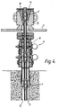
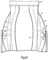
- casing centralizers now to be described with reference to the drawings can be utilized in in oil well of the kind shown in Figure 1.
- oil bearing deposits are reached from a drilling derrick 1, and are not only located at great depths but also at a position horizontally spaced from the derrick location.
- the bore 2 as a whole consequently forms in arc merging from the vertical into the horizontal through, the rock, and this bore 2 has to be followed by a casing string 3 comprising individual casings 11.
- the force with which the pipeline bears on the bore sides creates considerable frictional forces, especially in the case of a horizontal run, which may damage the casing string.
- the casing string 3 is protected against contact with the rock by means of centralizers 4 of the kinds to be described below.
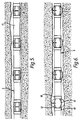
- the first form of centralizer comprises a pair of metal sleeves 10 whose interior diameter is substantially equal to the exterior diameter of a casing 11 of a casing string for an oil well borehole.
- a typical casing diameter may be 125 mm.
- Each spring strip 12 is connected between the sleeves and spaced equi-angularly around the sleeves 10.
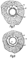
- Each spring strip has a bowed unstressed profile as shown in Figure 3 and is provided intermediate its ends with a channel 13.
- the sleeves 10 are located on a casing 11 by spanning a joint between casings 11 between a stop collar (not shown) such that the sleeves can slide on the casing to a limited degree.
- a band 14 is placed around the spring strips 12 in the channels 13 and is tightened to draw the spring, strips 12 against the outer surface of the casing 11, as seen in Figure 2. This moves the sleeves 10 to a maximum spacing.
- the band 14 is held tight by a titanium link 15.
- each bore 2 is provided at the open upper end, below a working deck 5 of the derrick, with a safety and control valve system 6 as an assurance against gas and oil eruptions.
- This so-called piping head 6 is provided with a through passage 7 with cross-sections which are substantially smaller than the cross-section of the bore 2 itself.
- Above the working deck 5 is situated a housing 8 incorporating catching wedges 9 for guiding the casing string 3 into the bore 2.
- the passage cross-sections are small compared to the bore diameter in the rock.
- the centralizer 4 described above with reference to Figures 2 and 3 of the drawings passes readily through the housing 8 and through the piping head 6, because the spring strips 12 are held closely adjacent the surface of the casing string 3. This overcomes a problem of previous centralizers, where the spring strips are unstressed, and these must be forced through the housing 8 and the piping head 6.
- the casing string 3 is moved to a required position in the bore 2.
- the centralizer described above with reference to the drawings is held in the collapsed disposition until the associated casing is positioned in the borehole, there is no possibility of the centralizer snagging and preventing movement of the casing 11.
- the amount of bowing can be greater than with conventional centralizers, whose bowing is limited in order to reduce the possibility of snagging.
- the titanium link 15 is very secure during movement of the casing but parts very reliably on contact with hydrofluoric acid.
- centralizer 4 Referring next to Figures 9 and 10, a second form of centralizer 4 will now be described. Parts of the first and second forms of centralizer are common and thus bear the same reference numerals and will not be described in detail.
- the narrow band 14 is replaced by a band 17 which overlies the whole of the centralizer.
- This wider band could be of a fabric or a plastics material.
- it has the advantage that it can hold a greater spring force from the spring strips 12 and also can hold the spring strips 12 in a lower profile.
- the band 17 may be rectangular and be formed into a casing holding the spring strips 12 by a titanium wire stitched along the matching edges of the band 17. The wire is then reacted with hydrofluoric acid, as described above, when the casing 11 is positioned in a borehole as described above. This will allow the spring strips 12 to move to the deployed position shown in Figures 6 and 8 for engagement with the borehole, as described above.
- the band 14,17 need not be held by the use of titanium or released by the use of hydrofluoric acid.
- the band 14,17 could be held by some other material which can be reacted with a particular chemical to weaken the material and release the band when required.
- the band 14,17 could be held by some device which releases the band after a specified time or delay or by a device which is actuated to release the band 14,17, by electrical or magnetic means.
- centralizer In the third form of centralizer, four pairs of struts 18,19 are included, equally angularly spaced around the sleeves 10 intermediate the spring strips 12.
- the two struts 18,19 of each pair lie in a plane including the axis of the sleeves 10 and are pivotally connected together intermediate the sleeves 10.
- the ends opposite the pivotally connected ends, are themselves pivotally connected to an associated sleeve 10.
- struts 18,19 of each pair are aligned to one another close to an outer surface 16 of the casing 11. This causes the sleeves 10 to be moved to a maximum spacing which tends to hold the spring strips 12 in their collapsed disposition.
- a titanium sleeve 20 is slid over the pivotally connected ends of each pair of struts 18,19 to hold the struts in this disposition.
- the hydrofluoric acid also weakens the sleeve 20.
- This arrangement has the advantage that the struts 18,19 allow stronger spring strips 12 to be used than in the embodiments of Figures 2, 3, 10 and 11. They provide an additional force to keep the sleeves 10 at their maximum spacing.
- the spring strips 12 when deployed, the struts can engage the surrounding borehole and provide an additional centralizing force. This is best seen in the cross-sectional view in Figure 12.
- each strut 21 is provided spaced equi-angularly around the sleeves intermediate the spring strips.
- Each strut 21 has one end fixed to a sleeve 25 which is not connected to the casing 11 and extends parallel to the axis of the sleeves 25 and through apertures 22 in a sleeve 26 which is fixed to the casing.
- An end of each strut 21 projecting beyond the fixed sleeve 26 is received in an energizing device 23.
- the band 17 is released as described above.
- the spring strips then move to a first deployed position which is shown in Figure 14. This results in the strut engaging in the energizing device, as seen in Figure 14.
- the energizing device 23 is then actuated to move along the casing 11 as shown in Figure 15 in a direction away from the fixed sleeve 26. This draws the movable sleeve 25 closer to the fixed sleeve 26 and so increases the bowing of the spring strips 12.
- the strut 21 and the fixed sleeve 26 may include a ratchet arrangement which prevents return movement of the strut 21.
- the energizing device 23 may be actuated in any convenient way.
- One such way is shown in Figure 17.
- the energizing device 23 is in communication with the interior of casing 11.
- a liquid under high pressure is passed through coiled tubing between two plugs 24.
- the plugs 24 are deployed to define a closed chamber in that section of the casing which communicates with the device 23.
- the chamber pressure is then increased with high pressure liquid from the coil and this liquid acuates the energizing device 23.
- the whole casing could be pressurized.
- the energizing device 23 may be operated by provision of projecting fins or similar members which are arranged in the annulus between the casing 11 and the borehole and which act to move the energizing device when the pressure of material in the annulus is increased.
- centralizers described above with reference to the drawings have four spring strips, it will be appreciated that they may be provided with more or less spring strips.
- all the forms of centralizer have spring strips extending between two sleeves, the embodiments of Figures 2, 3, 9 and 10 in particular, may include only one sleeve. In this case, the spring strips may, in their deployed disposition, simply extend at an angle away from the casing surface 16.
- the band 14 of the embodiment of Figures 2 and 3 need not be released using an acid, as described above with reference to those Figures.
- an acid as described above with reference to those Figures.
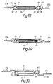
- a locking device is provided to control release of the band 14, in the form of a pressure element 30 comprising a piston 31, which is displaceably mounted in the cylindrical bore of the pressure element.
- the cylindrical bore is closed by means of a cover 33 which has a central opening 34 through which extends a pin 35 of the piston 31.
- a second cover 36 which may for example be secured via spacer screws, is placed at a distance from the cover 13.
- Two extremities 37a and 37b of the band 14 engage in the gap between the covers.
- One extremity, 37a is provided with an opening which is aligned with the central openings of the covers 33 and 36.
- the piston pin 35 extends through the opening as shown.
- the band extremity 37b is immovably joined to the cover 33.
- the releasable extremity 37a is located between two guide pins 38 extending between the covers 33 and 36. Openings 39 in the covers 33 and 36 provide communication between one piston side and the ambient pressure.
- the piston side facing away from the piston pin 35 is acted upon by the pressure of the gas present in the free cylinder space, for example air.
- the gas column forms a gas spring whose force is overcome when the ambient pressure exceeds a limiting value.
- the piston 31 is then pushed back under appropriate compression of the gas volume within the free cylinder space. In doing so, it draws the pin 35 out of the central openings and releases the extremity 37a of the band 14.
- the spring strips 12 of the centralizer 4 are then free to expand into contact with the surface surrounding the pipe, e.g. the rock.
- the pressure element 30 is provided with a mechanical spring 40 instead of an air cushion.
- the side of the piston 31 which faces away from the spring may be acted upon by pressure via a duct 41.
- the covers 33 and 36 lack the openings for communication with the ambient atmosphere.
- a third form of locking device is shown in Figure 20 and largely resembles that of Figure 19.
- the force of the mechanical spring 40 is controlled by means of a controllable gas pressure of a working fluid charge, for example a gas or liquid, present in a free space between one piston side and the element cover 33.
- the charge is heated by means of an electrical resistance, which is not illustrated, within the free space.
- the electrical power is supplied via a feed conductor 45.
- the gas in the free space expands or the liquid is initially converted into a gaseous state, both of which provide a large increase in volume and lead to the piston 31 being thrust back against the force of the mechanical spring 40.
- the piston 31 again withdraws the pin 35 from the releasable extremity 37a of the band 14 and so releases the band 14.
- FIG. 21 A variation of the embodiment of Figure 20 is shown in Figure 21 in which the mechanical spring 40 is situated at the piston side facing towards the element cover 33.
- the free space 46 present in the rearwardly situated section is filled with a fusible substance which may be placed in a fluid condition by means of a heating resistance supplied via the electrical lead 45.
- the material, when made fluid may leave the cylinder space of the element 30 via draining orifices 47.
- the force of the spring assures a displacement of the piston 11, so drawing the pin 45 out of the opening of the band 14.
- the melting or dissolution of the fusible substance may be induced by the supply of thermal energy by geothermal heat, which increases with the depth. It may equally be envisaged to feed in a solvent via a duct, so that the material present in the solid state in the free cylinder space may be dissolved by a chemical action. This also includes the possibility of dissolving the material during the bore flushing operation. A combination of several possibilities may also be contemplated to ensure release.
- Figures 23 and 24 show a possible variation of the embodiment of Figure 22 in which a traction element 60, for example a cable, has one end fastened to the piston rod 50 projecting out of the pressure element.
- the other end of the traction cable 60 is solidly joined to a ring 61 which fits immovably on the casing 11.
- the traction cable 60 is tensioned by rotation of the whole casing string to withdraw the piston pin 35 from the opening of the stressing element extremity 37a.
- the pressure element then resembles the embodiment according to Figure 22, the free space being occupied either by an air cushion acting as a piston spring, or else by a mechanical spring.
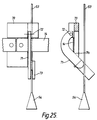
- FIG. 25 Another possible structure of the locking device is shown in Figure 25 in which both extremities of the band 4 are fixedly attached to a holding plate 70.
- a lever 71 is pivotally journalled on the holding plate 70 by means of a pivot pin 72.
- the lever 71 is constructed as a cutting tool appropriate for severing the band 4.
- a free end of the lever 71 carries a guiding element 73 for a traction cable 53 provided with a conical locking element 54 at its lower extremity. In use, the cone is drawn against the guiding element 73 when the cable 53 is pulled and transfers the tractive force to the lever 71, so that a cutting edge 71a of the cutting tool 71 severs the band 14 and releases the spring strips 12.
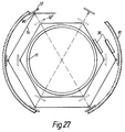
- Figures 26 and 27 show an alternative way of holding the spring strips 12 in a collapsed disposition using a band 14.
- the centralizer 4 comprises sleeves 10, Spring strips 12 extending between the sleeves 10 and a band 14.
- the spring strips 12 are indicated in the stressed state by a broken line and marked 12.
- Loops or eyes 80 are welded to the inward sides of the spring strips 12 and a straplike or cablelike band 14 is threaded through these loops or eyes 80. Since the eyes 80 are situated on the inward sides of the spring strips 12, their outer sides are not altered, so that no difficulties can be caused by sharp edges or corners.
- the centralizer 4 mounted on the casing 11 is drawn into an outer pipe, for example a lining pipe 81, and is placed in contact with its inward side by releasing the band 14 by operation of a locking device of any of the kinds described above with reference to the drawings.
- the casing 11 may thereby be held centrally in a conventional manner.
- each band extremity 37a, 37b is formed with two moulded parts 90,91 which together form two spaced chambers 92,93.
- One chamber 92 contains the positive half 94 of a battery.
- the other chamber 93 contains the negative half 95 of a battery.
- the extremities 37a, 37b of the bands 14 are held together by a wrap of material 96 of a thermoplastic or other heat-sensitive material.
- An electrically conductive wire 97 is connected at one end to the positive battery half 94 and passes through the wrap 96 to terminate at a magnet 98 located adjacent the negative battery half 95.
- the centralizer 4 is moved into a desired position as described above with reference to the drawings and an oil based mud containing iron filings is circulated through the casing string 3 and around the space between the casing string 3 and the borehole.
- an oil based mud containing iron filings is circulated through the casing string 3 and around the space between the casing string 3 and the borehole.
- the iron filings are attracted by the magnet 98 and form a conductive path 110 between the magnet and the negative half 95 of the battery. This completes the circuit and causes the conductive wire 97 to heat up in turn causing the wrap 97 to split.
- each band extremity is formed with a shaped part 99 with the two shaped parts 99 together cooperating to form a closed chamber 100.
- a membrane 101 divides the chamber 100 into two parts and each part contains a different chemical 102,103. The two chemicals are chosen such that, when they are mixed together, their volume increases rapidly.
- the membrane 101 holds a magnet 104 adjacent the radially outermost inner surface 105 of the chamber 100; the radial direction being measured relative to the axis of the casing 11 carrying the centralizer 4.
- a plug 106 is passed through the casing 11, as shown in Figure 32.
- the plug 106 carries a magnet 107 which, as it passes the closed chamber 100, attracts the chamber magnet 104. This breaks the membrane 101 so causing the two chemicals 102,103 to mix. This results in an increase in volume which separates the shaped parts 99 so releasing the band 14.
- the spring strips 12 thus move to the deployed position.
- the magnet 104 is held by the membrane 101 aligned in a radial direction relative to the axis of the associated casing 11. As the plug 106 is passed through the casing 11, the magnet 107 causes the chamber magnet 104 to rotate (see Figure 34) so breaking the membrane 101. The chemicals 102,103 then mix and expand as before, so releasing the band extremities 37a, 37b.
- the chamber magnet 104 is not moved by the plug. Rather, a wire line tool 108 is passed through the casing 11 which generates a strong magnetic field. This is sufficient to attract the chamber magnet 104 so breaking the membrane 101 and releasing the chemicals 102, 103, as before.
- the wire line tool 108 can also sense actuation of the chamber magnet 104 and release of the band 14, and can pass a corresponding signal to the surface.
- the ends of the band 14 could be held together by a pin which could be connected to wire leading to the top of the bore. Pulling on the wire would release the pin and allow the springs of the centralizer to expand against the side of the bore.
- the member 12 need not be a spring but could simply comprise a strip of metal which bowed outwardly against the side of the bore on movement of the energizing device 23.
- band 17 would not be necessary although a small outward bend in member 12 would be advantageous to facilitate bowing.
Claims (32)
- Zentrierkorb für Bohrlochfutterrohre mit einer Halterung (10) zur Befestigung des Zentrierkorbs (4) an der Außenfläche eines Futterrohres (11) und mehreren Teilen (12), die von der Halterung (10) mit Abständen um den Rohrumfang positioniert sind, wobei die Teile (12) durch eine Steuereinrichtung (15 Figur 2, 17 Figur 9; 26 Figur 13; 30 Figur 18) in einer zusammengefalteten Anordnung gehalten werden, in welcher die Teile (12) sich sehr dicht an der Außenfläche des Futterrohres (11) entlang erstrecken und die Steuervorrichtung (15 Figur 2; 17 Figur 9; 26 Figur 13; 30 Figur 18) fernbedienbar ist, so daß die Teile (12) sich aus der zusammengefalteten Anordnung in eine entfaltete Position bewegen, in welcher die Teile (12) sich von der Halterung (10) bis zur Anlage an ein entsprechend zugeordnetes Bohrloch erstreckt, dadurch gekennzeichnet, daß die Steuervorrichtung vollständig radial außerhalb oder vollständig radial innerhalb des Futterrohres positionierbar ist und, wenn sich das Futterrohr in der gewünschten Position befindet, fernbetätigt werden kann, um die Teile (12) zu entfalten.
- Zentrierkorb nach Anspruch 1, dadurch gekennzeichnet, daß jedes Teil (12) elastisch in Richtung auf seinen entfalteten Zustand vorgespannt ist und die Steuervorrichtung (15 Figur 2; 17 Figur 9; 26 Figur 13; 30 Figur 18) die Teile (12) gegen die Vorspannung im zusammengedrückten Zustand hält.
- Zentrierkorb nach Anspruch 2, dadurch gekennzeichnet, daß jedes Teil eine strelfenförmige Blattfeder (12) ist, deren Elastizität zu der Vorspannung führt.
- Zentrierkorb nach Anspruch 3, dadurch gekennzeichnet, daß die Halterung aus zwei mit Abstand voneinander angeordneten hülsenförmigen Ringen (10) besteht und die Enden jeder Blattfeder (12) mit den Hülsen verbunden sind, so daß sich die Blattfedern (12) im entfalteten Zustand zwischen den Ringen nach außen biegen.
- Zentrierkorb nach Anspruch 3 oder 4, dadurch gekennzeichnet, daß die Steuervorrichtung aus einem Band (14 Figur 2, 17 Figur 9) besteht, das sich um die Blattfedern (12) erstreckt und diese gegen die Vorspannung in der zusammengedrückten Anordnung hält, und daß das Band (14 Figur 2, 17 Figur 9) lösbar ist, um den Blattfedern (12) die Möglichkeit zu geben, sich in den entspannten Zustand zu bewegen.
- Zentrierkorb nach Anspruch 5, dadurch gekennzeichnet, daß das Band (14 Figur 2; 17 Figur 9) durch ein Teil (15) gehalten ist, das chemisch zum Lösen des Bandes zerlegbar ist.
- Zentrierkorb nach einem der Ansprüche 3 bis 6, dadurch gekennzeichnet, daß die Steuervorrichtung wenigstens ein paar scharnierförmig miteinander verbundene Streben aufweist, welche an ihren der Scharnierverbindung gegenüberliegenden Enden drehbar mit den entsprechenden Ringen (10) verbunden sind, wobei die Streben (18, 19) lösbar in einer Position gehalten werden, in welcher der Abstand zwischen den Ringen (10) ein Maximum aufweist, um die Blattfedern (12) in ihrem zusammengedrückten Zustand zu halten, und daß die Rückstellung die Streben (18, 19) so dreht, daß die Blattfedern (12) sich in ihre entspannte Position bewegen und der Abstand zwischen den Ringen (10) geringer wird.
- Zentrierkorb nach Anspruch 7, dadurch gekennzeichnet, daß die Streben (18, 19) durch ein Teil (20) gehalten werden, daß chemisch zerlegbar ist, um die Streben zu lösen.
- Zentrierkorb nach Anspruch 6 oder 8, dadurch gekennzeichnet, daß das Teil (15) aus Titan und der chemische Stoff Fluorwasserstoffsäure ist.
- Zentrierkorb nach einem der Ansprüche 7 bis 9, dadurch gekennzeichnet, daß für jede Blattfeder (12) ein Strebenpaar (18, 19) vorgesehen ist.
- Zentrierkorb nach einem der Ansprüche 3 bis 10, dadurch gekennzeichnet, daß die elastische Vorspannung jede Blattfeder in eine erste entfaltete Position bewegt, in welcher die Blattfeder (12) einen ersten Abstand von der zugehörigen Rohraußenfläche hat, und daß eine Betätigungsvorrichtung (23) vorgesehen ist, um die Blattfedern (12) in eine zweite entfaltete Position zu bringen, in welcher der Abstand vergrößert ist.
- Zentrierkorb nach Anspruch 11, dadurch gekennzeichnet, daß zwei Ringe (25, 26) für die sich zwischen den Ringen (25, 26) erstreckendenden Blattfedern (12) vorgesehen sind, von welchen ein Ring (25) an einem zugehörigen Rohr (11) fest angeordnet und der andere Ring (26) unbefestigt ist, daß eine Strebe (21) mit ihrem einen Ende an dem anderen Ring (26) befestigt ist und an ihrem gegenüberliegenden Ende mit der Betätigungsvorrichtung (23) in Berührung steht, daß die Betätigungsvorrichtung (23) betätigbar ist, wenn die Blattfedern (12) in der ersten entfalteten Position sind, um die Strebe (21) zu bewegen und den anderen Ring (26) zu zwingen, an den ersten Ring (25) heranzurücken, um eine verstärkte Biegung der Blattfedern (12) in ihre zweite Entfaltungsposition hervorzurufen.
- Zentrierkorb nach Anspruch 12, dadurch gekennzeichnet, daß die Betätigungsvorrichtung eine hydraulische Vorrichtung (23) ist, die mit dem Innenraum eines entsprechenden Rohres (11) kommuniziert und durch hohen Flüssigkeitsdruck im Innenraum des Rohres (11) betätigt wird.
- Zentrierkorb nach Anspruch 5, dadurch gekennzeichnet, daß das Band (14) an den Innenseiten der Blattfedern (12) um den Zentrierkorb (4) herumgeführt ist, und daß die äußersten Enden (37a, 37b) des Bandes (14) durch eine Verriegelungsvorrichtung (30, 33, 35) gehalten werden, um die Blattfedern (12) in ihrer zusammengelegten Anordnung zu halten, wobei die äußersten Enden (37a, 37b) von der Verriegelungsvorrichtung an einem vorbestimmten Punkt innerhalb des Bohrlochs lösbar sind, um es den Blattfedern (12) zu ermöglichen, den entfalteten Zustand anzunehmen.
- Zentrierkorb nach Anspruch 14, dadurch gekennzeichnet, daß die Führungselemente (80) zum Halten und Führen des Bandes (14) an den Innenseiten der Blattfedern (12) angebracht sind.
- Zentrierkorb nach Anspruch 14 oder 15, dadurch gekennzeichnet, daß die Verriegelungsvorrichtung aus einem Druckelement (30) mit einem darin angeordneten Kolben (31) besteht, der mit einem Stift (35) lösbar in eine Öffnung (34) eines der Bandenden (37) greift, daß der Kolben (31) sich normalerweise in einer Betriebsstellung befindet, in welcher der Stift (35) in das Bandende (37a) greift und aus der Betriebsposition entfernbar ist, um den Stift (35) aus dem Bandende (37a) zu entfernen und das Band (14) zu lösen.
- Zentrierkorb nach Anspruch 16, dadurch gekennzeichnet, daß das Druckelement (30) aus einem zylindrischen Gehäuse mit einer Abdeckung (33) besteht, in welcher sich eine zentrale Öffnung befindet, durch welche der Kolbenstift (35) nach außen und in die Öffnung eines Endes (37a) des Bandes (14) faßt, daß sich die Enden (37a, 37b) des Bandes (14) zwischen der Abdeckung (33) und einer Halteplatte (36) befinden, die an der Abdeckung befestigt ist, welche mit einer zentralen Öffnung zur Aufnahme des Kolbenstiftes (35) versehen ist.
- Zentrierkorb nach Anspruch 16 oder 17, dadurch gekennzeichnet, daß das Druckelement (30) mit Öffnungen (39) versehen ist, um der umgebenden Atmosphäre die Möglichkeit zu geben, auf eine Seite des Kolbens zu wirken, um diesen aus der Betriebsposition zu bewegen.
- Zentrierkorb nach Anspruch 16 oder 17, dadurch gekennzeichnet, daß der Kolben (31) mit Hilfe eines unter Druck stehenden Gases in Richtung auf die Betriebsposition vorgespannt ist.
- Zentrierkorb nach Anspruch 16 oder 17, dadurch gekennzeichnet, daß der Kolben (31) mit Hilfe einer mechanischen Feder (40) in Richtung auf die Betriebsposition vorgespannt ist.
- Zentrierkorb nach Anspruch 20, dadurch gekennzeichnet, daß das Druckelement an eine Steuerdruckleitung (41) angeschlossen ist, um die der Kolbenfeder (40) gegenüberliegenden Kolbenseite mit einer unter Druck stehenden Flüssigkeit zu beaufschlagen und den Kolben (31) aus der Betriebsposition zu bewegen.
- Zentrierkorb nach Anspruch 19 oder 20, dadurch gekennzeichnet, daß das Druckelement mit einem Heizwiderstand (45) zur Steuerung der Temperatur einer sich darin befindenden Arbeitsflüssigkeit ausgerüstet ist, wobei die Aufheizung der Flüssigkeit den Kolben (31) aus der Betriebsposition bewegt.
- Zentrierkorb nach Anspruch 19 oder 20, dadurch gekennzeichnet, daß das Druckelement mit Auslaßöffnungen (47) versehen ist und eine Arbeitssubstanz fester Konsistenz enthält, die bei Bedarf verflüssigbar ist und durch die Drainagelöcher (47) austritt, so daß die Verflüssigung der Arbeitssubstanz dazu führt, den Kolben (31) aus der Betriebsposition zu bewegen.
- Zentrierkorb nach Anspruch 20, dadurch gekennzeichnet, daß der Kolben (31) gegen die Kraft der Feder (40) mit Hilfe eines Hebelmechanismus in die Außerbetriebsstellung bewegbar ist.
- Zentrierkorb nach Anspruch 24, dadurch gekennzeichnet, daß der Kolben (31) mit einer Kolbenstange (50) versehen ist, die sich nach außen durch eine zentrale Öffnung des Druckelements (30) erstreckt und beweglich mit einem Hebel (51) verbunden ist, der sich an der Rückwand des Elements (30) abstützt und dessen freies Ende durch ein Zugelement (53) von der Oberfläche betätigbar ist.
- Zentrierkorb nach Anspruch 25, dadurch gekennzeichnet, daß sich das Zugelement (53) durch eine durch das freie Ende des Hebels (51) geformte Schlaufe erstreckt, daß ein Ende des Elements (53) ein Formteil (54) trägt, welches bei der Betätigung des Zugelements (53) die Schlaufe erfaßt, um den Hebel (51) zu schwenken und den Kolben (31) aus der Betriebsposition zu bewegen.
- Zentrierkorb nach Anspruch 14 oder 15, dadurch gekennzeichnet, daß die Verriegelungsvorrichtung mit einem Trennwerkzeug zum Lösen des Bandes (14) versehen ist.
- Zentrierkorb nach Anspruch 27, dadurch gekennzeichnet, daß die Enden (37a, 37b) des Bandes (14) fest mit einer Platte (70) verbunden sind, die ein drehbares Schneidwerkzeug (71) trägt, welches mit einem Zugelement (73) zur Betätigung des Schneidwerkzeugs (71) ausgerüstet ist, um das Band (14) zu zerschneiden und die Blattfedern (12) zu lösen.
- Zentrierkorb nach Anspruch 16, dadurch gekennzeichnet, daß der Kolben (31) mit einer sich durch eine Zentralöffnung des Elements (30) nach außen erstreckenden Kolbenstange versehen ist, an welcher ein Ende eines Zugkabels (60) befestigt ist, dessen anderes Ende fest mit einem Befestigungsring (61) verbunden ist, der auf einem Rohr (11), das den Zentrierkorb (4) trägt, installiert ist, so daß eine relative Verdrehung des Zentrierkorbs (4) zum Rohr (11) den Kolben (31) aus der Betriebsposition bewegt.
- Zentrierkorb nach Anspruch 5, dadurch gekennzeichnet, daß die Enden (37a, 37b) des Bandes (14) durch eine Umhüllung (96) zusammengehalten werden, um die Blattfedern (12) im zusammengefalteten Zustand zu halten, daß sich ein Leitungsdraht um die Hülle erstreckt und mit einem Ende an dem einen Pol (94) einer elektrischen Batterie befestigt ist, dessen anderes Ende an einen Magneten (98) angeschlossen ist, der sich neben einem Ende des Gegenpols (95) der Batterie befindet, daß der Durchgang einer Flüssigkeit mit magnetisch leitenden Partikeln vorbei am Band (14) dazu führt, daß die Partikel am Magnet (98) haften und eine Leitungsbrücke zwischen dem Draht (97) und dem anderen Batteriepol (95) bilden, so daß sich der leitende Draht (97) erhitzt und die Umhüllung (96) trennt, so daß sich die Blattfedern (12) in den entfalteten Zustand bewegen.
- Zentrierkorb nach Anspruch 5, dadurch gekennzeichnet, daß das Band (14) zwei Enden (37a, 37b) hat, von welchen jedes einem Kammerteil (99) zugeordnet ist, die eine geschlossene Kammer (100) bilden, daß die Kammer (100) durch eine Membran (101) unterteilt ist und eine Abteilung eine erste Substanz und die andere Abteilung eine zweite Substanz enthalten, daß Mittel (104) zum Zerstören der Membran (101) vorgesehen sind, damit sich die Substanzen vermischen können, und daß die Substanzen derart sind, daß sich ihr Volumen beim Mischen vergrößert und die Kammerteile (99) voneinander trennt und die Blattfedern (12) für ihren entfalteten Zustand freigeben.
- Zentrierkorb nach Anspruch 31, dadurch gekennzeichnet, daß das Mittel zum Zerstören ein Magnet (104) ist, der durch die Membran gehalten wird, und daß die Membran (101) durch die Bewegung des Magneten (104) unter der Wirkung einer ausgeübten magnetischen Kraft zerstört wird.
Applications Claiming Priority (5)
| Application Number | Priority Date | Filing Date | Title |
|---|---|---|---|
| GB909001007A GB9001007D0 (en) | 1990-01-17 | 1990-01-17 | Centralizers for oil well casings |
| GB9001007 | 1990-01-17 | ||
| DE19904024000 DE4024000C2 (de) | 1990-07-28 | 1990-07-28 | Rohrzentrierkorb mit Spanneinrichtung |
| DE4024000 | 1990-07-28 | ||
| PCT/GB1991/000065 WO1991010806A1 (en) | 1990-01-17 | 1991-01-17 | Centralizers for oil well casings |
Publications (2)
| Publication Number | Publication Date |
|---|---|
| EP0511254A1 EP0511254A1 (de) | 1992-11-04 |
| EP0511254B1 true EP0511254B1 (de) | 1995-03-01 |
Family
ID=25895437
Family Applications (1)
| Application Number | Title | Priority Date | Filing Date |
|---|---|---|---|
| EP91902218A Expired - Lifetime EP0511254B1 (de) | 1990-01-17 | 1991-01-17 | Zentriervorrichtung für ölfeldfutterrohr |
Country Status (7)
| Country | Link |
|---|---|
| US (1) | US5261488A (de) |
| EP (1) | EP0511254B1 (de) |
| AT (1) | ATE119234T1 (de) |
| CA (1) | CA2073332C (de) |
| DE (1) | DE69107833T2 (de) |
| NO (1) | NO305256B1 (de) |
| WO (1) | WO1991010806A1 (de) |
Families Citing this family (74)
| Publication number | Priority date | Publication date | Assignee | Title |
|---|---|---|---|---|
| US5097905A (en) * | 1991-01-28 | 1992-03-24 | Mobil Oil Corporation | Centralizer for well casing |
| US5411049A (en) * | 1994-03-18 | 1995-05-02 | Weatherford U.S., Inc. | Valve |
| US5680902A (en) * | 1994-03-22 | 1997-10-28 | Weatherford/Lamb, Inc. | Wellbore valve |
| US5836395A (en) * | 1994-08-01 | 1998-11-17 | Weatherford/Lamb, Inc. | Valve for wellbore use |
| GB9405679D0 (en) * | 1994-03-22 | 1994-05-11 | Weatherford Lamb | Fill valve |
| US5909771A (en) * | 1994-03-22 | 1999-06-08 | Weatherford/Lamb, Inc. | Wellbore valve |
| GB9419313D0 (en) * | 1994-09-24 | 1994-11-09 | Weatherford Lamb | Centralisers |
| GB9425240D0 (en) * | 1994-12-14 | 1995-02-08 | Head Philip | Dissoluable metal to metal seal |
| GB2299598B (en) * | 1995-04-07 | 1999-03-17 | Weatherford Lamb | Apparatus for use in a wellbore |
| US5575333A (en) * | 1995-06-07 | 1996-11-19 | Weatherford U.S., Inc. | Centralizer |
| US6220350B1 (en) * | 1998-12-01 | 2001-04-24 | Halliburton Energy Services, Inc. | High strength water soluble plug |
| US6374918B2 (en) | 1999-05-14 | 2002-04-23 | Weatherford/Lamb, Inc. | In-tubing wellbore sidetracking operations |
| US6533034B1 (en) | 2000-05-15 | 2003-03-18 | Flotek Industries, Inc. | Centralized stop collar for floating centralizer |
| EG22932A (en) * | 2000-05-31 | 2002-01-13 | Shell Int Research | Method and system for reducing longitudinal fluid flow around a permeable well tubular |
| US7182131B2 (en) * | 2000-09-06 | 2007-02-27 | Casetech International, Inc. | Dual diameter and rotating centralizer/sub and method |
| US7156171B2 (en) * | 2000-09-06 | 2007-01-02 | Casetech International, Inc. | Dual diameter and rotating centralizer/sub |
| US6679325B2 (en) | 2002-02-08 | 2004-01-20 | Frank's International, Inc. | Minimum clearance bow-spring centralizer |
| US7168494B2 (en) * | 2004-03-18 | 2007-01-30 | Halliburton Energy Services, Inc. | Dissolvable downhole tools |
| GB0413042D0 (en) * | 2004-06-11 | 2004-07-14 | Petrowell Ltd | Sealing system |
| GB0423992D0 (en) * | 2004-10-29 | 2004-12-01 | Petrowell Ltd | Improved plug |
| GB0507237D0 (en) * | 2005-04-09 | 2005-05-18 | Petrowell Ltd | Improved packer |
| CA2681603C (en) | 2006-03-23 | 2014-05-13 | Petrowell Limited | Improved packer |
| US20070284097A1 (en) | 2006-06-08 | 2007-12-13 | Halliburton Energy Services, Inc. | Consumable downhole tools |
| US20080257549A1 (en) | 2006-06-08 | 2008-10-23 | Halliburton Energy Services, Inc. | Consumable Downhole Tools |
| US7341105B2 (en) | 2006-06-20 | 2008-03-11 | Holcim (Us) Inc. | Cementitious compositions for oil well cementing applications |
| GB0622916D0 (en) * | 2006-11-17 | 2006-12-27 | Petrowell Ltd | Improved tree plug |
| US20080202764A1 (en) | 2007-02-22 | 2008-08-28 | Halliburton Energy Services, Inc. | Consumable downhole tools |
| US20080264629A1 (en) * | 2007-04-24 | 2008-10-30 | Frank's International, Inc. | Field-Assemblable Bow-Spring Casing Centralizer and Method of Making A Centralizer |
| ATE536462T1 (de) * | 2007-05-16 | 2011-12-15 | Frank S Inr Inc | Erweiterbare zentrierer für erweiterbaren rohrstrang |
| US8196654B2 (en) * | 2007-05-16 | 2012-06-12 | Frank's International, Inc. | Expandable centralizer for expandable pipe string |
| US9771763B2 (en) | 2007-05-16 | 2017-09-26 | Antelope Oil Tool & Mfg. Co. | Low-clearance centralizer |
| US7878241B2 (en) * | 2007-05-16 | 2011-02-01 | Frank's International, Inc. | Expandable centralizer for expandable pipe string |
| US8701783B2 (en) * | 2007-07-26 | 2014-04-22 | Antelope Oil Tool & Mfg. Co., Llc | Apparatus for and method of deploying a centralizer installed on an expandable casing string |
| US8763690B2 (en) | 2007-05-16 | 2014-07-01 | Antelope Oil Tool & Mfg. Co., Llc | Casing centralizers having flexible bow springs |
| US7845061B2 (en) * | 2007-05-16 | 2010-12-07 | Frank's International, Inc. | Low clearance centralizer and method of making centralizer |
| GB0711871D0 (en) * | 2007-06-20 | 2007-07-25 | Petrowell Ltd | Improved activation device |
| US7967065B2 (en) * | 2007-11-30 | 2011-06-28 | Frank's Casing Crew And Rental Tools, Inc. | Caisson system |
| AU2014277766B2 (en) * | 2007-12-03 | 2016-04-21 | Weatherford Technology Holdings, Llc | Improved centraliser |
| AU2016204890B2 (en) * | 2007-12-03 | 2018-05-10 | Weatherford Technology Holdings, Llc | Improved centraliser |
| GB0723607D0 (en) * | 2007-12-03 | 2008-01-09 | Petrowell Ltd | Improved centraliser |
| US8291781B2 (en) * | 2007-12-21 | 2012-10-23 | Schlumberger Technology Corporation | System and methods for actuating reversibly expandable structures |
| US8733453B2 (en) * | 2007-12-21 | 2014-05-27 | Schlumberger Technology Corporation | Expandable structure for deployment in a well |
| US7766580B2 (en) | 2008-02-14 | 2010-08-03 | National Oilwell Varco, L.P. | Energy managing keel joint |
| GB0803123D0 (en) * | 2008-02-21 | 2008-03-26 | Petrowell Ltd | Improved tubing section |
| GB0804961D0 (en) * | 2008-03-18 | 2008-04-16 | Petrowell Ltd | Improved centraliser |
| US8235102B1 (en) | 2008-03-26 | 2012-08-07 | Robertson Intellectual Properties, LLC | Consumable downhole tool |
| US8327926B2 (en) | 2008-03-26 | 2012-12-11 | Robertson Intellectual Properties, LLC | Method for removing a consumable downhole tool |
| GB0805719D0 (en) * | 2008-03-29 | 2008-04-30 | Petrowell Ltd | Improved tubing section coupling |
| US20090308615A1 (en) * | 2008-06-11 | 2009-12-17 | Frank's International, Inc. | Modular Low-Clearance Centralizer and Method of Making Modular Low-Clearance Centralizer |
| US8245777B2 (en) * | 2008-07-25 | 2012-08-21 | Stephen Randall Garner | Tubing centralizer |
| US8235109B2 (en) * | 2008-09-26 | 2012-08-07 | Schlumberger Technology Corporatio | Instrument centralizer configurable for use with cement evaluation well logging instruments |
| US8360161B2 (en) * | 2008-09-29 | 2013-01-29 | Frank's International, Inc. | Downhole device actuator and method |
| US20120073803A1 (en) | 2009-06-08 | 2012-03-29 | Shantanu Dalmia | Dual rotary centralizer for a borehole |
| US20110042102A1 (en) * | 2009-08-18 | 2011-02-24 | Frank's International, Inc. | Method of and kit for installing a centralizer on a pipe segment |
| US8408287B2 (en) * | 2010-06-03 | 2013-04-02 | Electro-Petroleum, Inc. | Electrical jumper for a producing oil well |
| WO2013135297A1 (en) * | 2012-03-15 | 2013-09-19 | Statoil As | Centralizer for expandable casing |
| BR112014023345B1 (pt) * | 2012-03-20 | 2021-03-23 | Blackhawk Specialty Tools, Llc | Centralizador de poço e método para instalar um centralizador em um poço |
| US8960278B2 (en) * | 2012-06-04 | 2015-02-24 | Halliburton Energy Services, Inc. | Pull through centralizer |
| US8991487B2 (en) | 2012-06-04 | 2015-03-31 | Halliburton Energy Services, Inc. | Pull through centralizer |
| US9580976B1 (en) | 2013-03-14 | 2017-02-28 | Sandia Corporation | Deployable centralizers |
| US9725967B2 (en) | 2013-07-24 | 2017-08-08 | Bp Corporation North America Inc. | Centralizers for centralizing well casings |
| US10113372B2 (en) | 2013-07-30 | 2018-10-30 | Weatherford Technology Holdings, Llc | Centralizer |
| US10280695B2 (en) | 2014-06-27 | 2019-05-07 | Weatherford Technology Holdings, Llc | Centralizer |
| NO338218B1 (no) * | 2014-07-02 | 2016-08-08 | Moonshine Solutions As | Utløserinnretning og fremgangsmåte for utplassering av brønnhullkomponent i borehull |
| US10161198B2 (en) | 2015-07-08 | 2018-12-25 | Weatherford Technology Holdings, Llc | Centralizer with integrated stop collar |
| US20180298699A1 (en) * | 2015-12-16 | 2018-10-18 | Halliburton Energy Services, Inc. | Energized Downhole Standoff |
| WO2018085102A1 (en) * | 2016-11-03 | 2018-05-11 | Terves Inc. | Self-actuating device for centralizing an object |
| GB201806327D0 (en) | 2018-04-18 | 2018-05-30 | Downhole Products Ltd | Centraliser assembly |
| US20210270092A1 (en) * | 2018-08-10 | 2021-09-02 | Downhole Products Limited | Centralizer having atmospheric chamber for expansion in response to hydrostatic pressure |
| US10895117B2 (en) | 2018-12-28 | 2021-01-19 | Saudi Arabian Oil Company | Systems and methods for improved centralization and friction reduction using casing rods |
| CN110043200B (zh) * | 2019-04-22 | 2020-07-24 | 中国农业大学 | 一种磁信号激活的可变径扶正器 |
| US11125024B2 (en) * | 2019-07-26 | 2021-09-21 | Innovex Downhole Solutions, Inc. | Centralizer with dissolvable retaining members |
| WO2021022093A1 (en) | 2019-08-01 | 2021-02-04 | Chevron U.S.A. Inc. | Artificial lift systems utilizing high speed centralizers |
| US11459846B2 (en) * | 2019-08-14 | 2022-10-04 | Terves, Llc | Temporary well isolation device |
Family Cites Families (7)
| Publication number | Priority date | Publication date | Assignee | Title |
|---|---|---|---|---|
| US2490350A (en) * | 1943-12-15 | 1949-12-06 | Claude C Taylor | Means for centralizing casing and the like in a well |
| US2656890A (en) * | 1951-08-02 | 1953-10-27 | Arthur H Brandon | Adjustable belly spring |
| US3343608A (en) * | 1966-08-10 | 1967-09-26 | B & W Inc | Two-stage centralizer |
| US4543998A (en) * | 1983-11-17 | 1985-10-01 | Regal International, Inc. | Protector clamp for well control lines |
| US4523640A (en) * | 1984-01-23 | 1985-06-18 | Dresser Industries, Inc. | Arm release system for well logging apparatus |
| US4688636A (en) * | 1986-04-11 | 1987-08-25 | Albert Hennessey | Non-weld casing centralizer |
| US4651823A (en) * | 1986-05-19 | 1987-03-24 | Antelope Oil Tool & Mfg. Company | Centralizer |
-
1991
- 1991-01-17 US US07/910,135 patent/US5261488A/en not_active Expired - Lifetime
- 1991-01-17 CA CA002073332A patent/CA2073332C/en not_active Expired - Lifetime
- 1991-01-17 WO PCT/GB1991/000065 patent/WO1991010806A1/en active IP Right Grant
- 1991-01-17 DE DE69107833T patent/DE69107833T2/de not_active Expired - Fee Related
- 1991-01-17 AT AT91902218T patent/ATE119234T1/de not_active IP Right Cessation
- 1991-01-17 EP EP91902218A patent/EP0511254B1/de not_active Expired - Lifetime
-
1992
- 1992-07-10 NO NO922736A patent/NO305256B1/no not_active IP Right Cessation
Also Published As
| Publication number | Publication date |
|---|---|
| EP0511254A1 (de) | 1992-11-04 |
| NO305256B1 (no) | 1999-04-26 |
| DE69107833T2 (de) | 1995-11-09 |
| NO922736L (no) | 1992-07-10 |
| CA2073332A1 (en) | 1991-07-18 |
| ATE119234T1 (de) | 1995-03-15 |
| NO922736D0 (no) | 1992-07-10 |
| DE69107833D1 (de) | 1995-04-06 |
| CA2073332C (en) | 1999-09-28 |
| WO1991010806A1 (en) | 1991-07-25 |
| US5261488A (en) | 1993-11-16 |
Similar Documents
| Publication | Publication Date | Title |
|---|---|---|
| EP0511254B1 (de) | Zentriervorrichtung für ölfeldfutterrohr | |
| US4671356A (en) | Through tubing bridge plug and method of installation | |
| US6003607A (en) | Wellbore equipment positioning apparatus and associated methods of completing wells | |
| CA1294869C (en) | Permanent anchor for use with through tubing bridge plug | |
| US6053248A (en) | Methods of completing wells utilizing wellbore equipment positioning apparatus | |
| US3398803A (en) | Single trip apparatus and method for sequentially setting well packers and effecting operation of perforators in well bores | |
| US3208530A (en) | Apparatus for setting bridge plugs | |
| AU717334B2 (en) | Activation of downhole tools | |
| US2798559A (en) | Hangers for well tubing extensions and the like | |
| CA2211228A1 (en) | Liner wiper plug apparatus and method | |
| US9945197B2 (en) | Tool positioning and latching system | |
| US20130248252A1 (en) | Reaming Shoe for Increased Borehole Clearance | |
| GB2206626A (en) | Running tool | |
| AU719893B2 (en) | Mill for wellbore milling operations | |
| BRPI0807531B1 (pt) | Ferramenta de comunicação para estabelecer comunicação de fluido entre uma linha de controle e um dispositivo de fundo de poço e método para estabelecer comunicação de fluido com um dispositivo de fundo de poço | |
| GB2289298A (en) | Permanent whipstock | |
| US4122899A (en) | Well perforator with anchor and method | |
| GB2339817A (en) | Gravel packing a well | |
| US20140338908A1 (en) | Cementing whipstock apparatus and methods | |
| US3032108A (en) | Well packer apparatus | |
| US11655684B2 (en) | System for dislodging and extracting tubing from a wellbore | |
| CA3121970C (en) | Downhole circular cutting torch | |
| US3020958A (en) | Well tool | |
| US20090151951A1 (en) | Adjustable Diameter Fishing Tool | |
| US9605510B2 (en) | Non-rotating connector for wellbore cementing tool |
Legal Events
| Date | Code | Title | Description |
|---|---|---|---|
| PUAI | Public reference made under article 153(3) epc to a published international application that has entered the european phase |
Free format text: ORIGINAL CODE: 0009012 |
|
| 17P | Request for examination filed |
Effective date: 19920612 |
|
| AK | Designated contracting states |
Kind code of ref document: A1 Designated state(s): AT DE FR GB IT NL |
|
| RAP1 | Party data changed (applicant data changed or rights of an application transferred) |
Owner name: WEATHERFORD/LAMB, INC. (A TEXAS CORPORATION) |
|
| RAP1 | Party data changed (applicant data changed or rights of an application transferred) |
Owner name: WEATHERFORD/LAMB, INC. (A DELAWARE CORPORATION) |
|
| 17Q | First examination report despatched |
Effective date: 19930909 |
|
| GRAA | (expected) grant |
Free format text: ORIGINAL CODE: 0009210 |
|
| AK | Designated contracting states |
Kind code of ref document: B1 Designated state(s): AT DE FR GB IT NL |
|
| PG25 | Lapsed in a contracting state [announced via postgrant information from national office to epo] |
Ref country code: AT Effective date: 19950301 |
|
| REF | Corresponds to: |
Ref document number: 119234 Country of ref document: AT Date of ref document: 19950315 Kind code of ref document: T |
|
| ET | Fr: translation filed | ||
| REF | Corresponds to: |
Ref document number: 69107833 Country of ref document: DE Date of ref document: 19950406 |
|
| ITF | It: translation for a ep patent filed |
Owner name: GUZZI E RAVIZZA S.R.L. |
|
| PLBE | No opposition filed within time limit |
Free format text: ORIGINAL CODE: 0009261 |
|
| STAA | Information on the status of an ep patent application or granted ep patent |
Free format text: STATUS: NO OPPOSITION FILED WITHIN TIME LIMIT |
|
| 26N | No opposition filed | ||
| REG | Reference to a national code |
Ref country code: FR Ref legal event code: TP |
|
| REG | Reference to a national code |
Ref country code: GB Ref legal event code: IF02 |
|
| PGFP | Annual fee paid to national office [announced via postgrant information from national office to epo] |
Ref country code: FR Payment date: 20030110 Year of fee payment: 13 |
|
| PGFP | Annual fee paid to national office [announced via postgrant information from national office to epo] |
Ref country code: NL Payment date: 20030130 Year of fee payment: 13 Ref country code: DE Payment date: 20030130 Year of fee payment: 13 |
|
| PG25 | Lapsed in a contracting state [announced via postgrant information from national office to epo] |
Ref country code: NL Free format text: LAPSE BECAUSE OF NON-PAYMENT OF DUE FEES Effective date: 20040801 |
|
| PG25 | Lapsed in a contracting state [announced via postgrant information from national office to epo] |
Ref country code: DE Free format text: LAPSE BECAUSE OF NON-PAYMENT OF DUE FEES Effective date: 20040803 |
|
| PG25 | Lapsed in a contracting state [announced via postgrant information from national office to epo] |
Ref country code: FR Free format text: LAPSE BECAUSE OF NON-PAYMENT OF DUE FEES Effective date: 20040930 |
|
| NLV4 | Nl: lapsed or anulled due to non-payment of the annual fee |
Effective date: 20040801 |
|
| REG | Reference to a national code |
Ref country code: FR Ref legal event code: ST |
|
| PG25 | Lapsed in a contracting state [announced via postgrant information from national office to epo] |
Ref country code: IT Free format text: LAPSE BECAUSE OF NON-PAYMENT OF DUE FEES Effective date: 20050117 |
|
| PGFP | Annual fee paid to national office [announced via postgrant information from national office to epo] |
Ref country code: GB Payment date: 20100113 Year of fee payment: 20 |
|
| REG | Reference to a national code |
Ref country code: GB Ref legal event code: PE20 Expiry date: 20110116 |
|
| PG25 | Lapsed in a contracting state [announced via postgrant information from national office to epo] |
Ref country code: GB Free format text: LAPSE BECAUSE OF EXPIRATION OF PROTECTION Effective date: 20110116 |