EP2242897B1 - Downhole seal - Google Patents
Downhole seal Download PDFInfo
- Publication number
- EP2242897B1 EP2242897B1 EP09707363A EP09707363A EP2242897B1 EP 2242897 B1 EP2242897 B1 EP 2242897B1 EP 09707363 A EP09707363 A EP 09707363A EP 09707363 A EP09707363 A EP 09707363A EP 2242897 B1 EP2242897 B1 EP 2242897B1
- Authority
- EP
- European Patent Office
- Prior art keywords
- sealing
- deflecting
- portions
- seal
- sealing portion
- Prior art date
- Legal status (The legal status is an assumption and is not a legal conclusion. Google has not performed a legal analysis and makes no representation as to the accuracy of the status listed.)
- Not-in-force
Links
Images


Classifications
-
- E—FIXED CONSTRUCTIONS
- E21—EARTH DRILLING; MINING
- E21B—EARTH DRILLING, e.g. DEEP DRILLING; OBTAINING OIL, GAS, WATER, SOLUBLE OR MELTABLE MATERIALS OR A SLURRY OF MINERALS FROM WELLS
- E21B33/00—Sealing or packing boreholes or wells
- E21B33/10—Sealing or packing boreholes or wells in the borehole
- E21B33/12—Packers; Plugs
- E21B33/1208—Packers; Plugs characterised by the construction of the sealing or packing means
Landscapes
- Geology (AREA)
- Life Sciences & Earth Sciences (AREA)
- Engineering & Computer Science (AREA)
- Mining & Mineral Resources (AREA)
- Environmental & Geological Engineering (AREA)
- Fluid Mechanics (AREA)
- Physics & Mathematics (AREA)
- General Life Sciences & Earth Sciences (AREA)
- Geochemistry & Mineralogy (AREA)
- Sealing Devices (AREA)
- Gasket Seals (AREA)
- Mechanical Sealing (AREA)
- Sealing With Elastic Sealing Lips (AREA)
Abstract
Description
- The present invention relates to a downhole seal, and in particular to a downhole seal which incorporates a swelling material.
- It is often necessary to establish seals in downhole locations, such as in hydrocarbon exploration and production wellbores. In many cases seals must be established in annular areas, such as between a tubing string and a wall of the wellbore, for example an open bore wall or a cased or lined bore wall. Annular seals of the type described are conventionally identified as packers.
- Many forms of downhole seals or packers are currently utilised which are arranged or mounted on the outer surface of a tubing string, such as a production tubing string or the like. Typically, the seals or packers are radially expandable such that they may be run into the wellbore while describing a reduced diameter, and then radially expanded to establish a seal at the required downhole location. Various arrangements exist for providing the required radial expansion. For example, seals may incorporate inflatable bladders which may be filled with a pressurised fluid. However, where high expansion ratios are required these inflatable bladders may become unstable, especially when exposed to large pressure differentials. Additionally, should the integrity of the bladder become compromised it may be difficult to maintain any form of seal.
- Mechanical expansion arrangements exist which involve the axial compression of an elastic or otherwise deformable material to cause the material to extend radially. Such mechanically expandable seals, however, have limited capabilities when large expansion ratios are required. Additionally, actuation of such mechanical arrangements may involve complicated assemblies to ensure sufficient operation, and to ensure that axial actuation forces are efficiently and accurately converted to the required radial forces to establish the required seal.
-
US 2003/0079887 discloses a mechanical expansion arrangement in which top and bottom sealing rings are disposed on either side of a double-ramped cylinder. An end of each sealing ring includes a metallic structure and an elastomeric material, wherein the ends are arranged to be outwardly deflected by the double ramped cylinder into contact with an outer tubular to establish a seal. This known arrangement provides a combined elastomeric and metal-to-metal seal against the outer tubular. - Expandable seals which incorporate swelling materials are also known. Such seals normally comprise a band of swellable material, such as a swelling elastomer, mounted on the outer surface of a tubular body. When the swellable material is exposed to a particular activator, such as water, oil or the like, the material will radially expand. While such swelling materials can readily achieve large expansion ratios, it is understood in the art that the mechanical properties of conventional swelling materials diminish with increasing expansion or swelling. Thus, highly swollen materials are often considered unsuitable for downhole use.
-
US 2007/0163777 which is considered the closest prior art, discloses a self energised packer which includes a central main sealing element formed of a swellable material, in addition to backup elements disposed on either side of the main sealing element The backup elements are provided to axially compress the main element to magnify its internal pressure. -
WO 2006/092530 discloses an open hole expandable patch which in one embodiment includes a swage which is axially compressed by a linearly moveable member to become radially enlarged. - As described above, many arrangements of expandable seals are known, although it is recognised that effective seals are very difficult to achieve where a high expansion ratio is required. This is a significant problem in the art as the architecture of a typical downhole environment normally requires a seal to be established in a large diameter bore, such as an overgauge or underreamed section, with access only provided through sections of a wellbore with relatively small internal diameters and restrictions. As such, seals which can accommodate such conventional downhole architecture and provide large expansion ratios are desired.
- According to a first aspect of the present invention there is provided an expandable downhole seal as set out in
claim 1. Alternative aspects according to the invention are set out in the dependent claims. - In use, radial expansion of the downhole seal may be achieved by the radial displacement of the sealing portion in combination with swelling of the swellable material. As such, the downhole seal of the present invention may advantageously be employed in environments where a large expansion ratio is required, such as in situations where the intended location of the seal can only be accessed via passageways or conduits of restricted or reduced internal dimensions and profiles.
- The entire sealing portion may be radially displaced. Alternatively, at least part of the sealing portion may be radially displaced.
- The sealing portion may be adapted to engage an inner surface of a bore, such as the inner surface of a open bore hole, a casing tubular, liner tubular or the like. In this manner the downhole seal may be adapted to establish a seal in an
- annulus or other suitably shaped region defined between a bore wall and the support member. The downhole seal may therefore be utilised as a packer.
- The downhole seal may be adapted to provide a downhole anchor, such as a tubing hanger or the like.
- The sealing portion may be adapted to directly engage the inner surface of a bore. Alternatively, the sealing portion may be adapted to indirectly engage the inner surface of a bore, for example via a further sealing portion, resilient material, deformable material, sealing material, or the like, or any suitable combination thereof.
- It should be understood that relative axial movement of the sealing and deflecting portions and subsequent radial displacement of the sealing portion may be achieved with reference to the support member. The support member may be solid, hollow or the like. In one embodiment the support member may comprise a tubular member, such as a production tubular, casing tubular, liner tubular, coiled tubing or the like. The support member may be unitary. Alternatively, the support member may comprise a plurality of sections, which sections may be coupled together. For example, the support member may comprise a plurality of tubular bodies coupled together in end-to-end relation to define a tubing string. The sealing and deflecting portions may be provided on a single section, or on different sections of the support member. At least one of the sealing and deflecting portions may function as a connector to permit different sections of the support member to be connected together.
- One of the sealing and deflecting portions may be fixed relative to the support member and the other of the sealing and deflecting portions may be axially moveable relative to the support member. Alternatively, both the sealing and deflecting portions may be axially moveable. Accordingly, relative axial movement of the sealing and deflecting portions may be achieved by displacement of one or both of said portions.
- Relative axial movement of the sealing and deflecting portions may be achieved hydraulically, pneumatically, mechanically or the like. For example, relative axial movement may be achieved by a piston arrangement, motor drive or the like. It should be understood, however, that any suitable arrangement for achieving relative axial movement of the sealing and deflecting portions may be utilised, as would be readily selected by a person of skill in the art.
- The sealing and deflecting portions may be adapted to interengage, either directly or indirectly, upon relative axial movement thereof, wherein said interengagement effects radial displacement of the sealing portion. Interengagement of the sealing and deflecting portions may be achieved by overlapping of said portions in an axial direction. In one embodiment, one of the sealing and deflecting portions may axially overlap an outer surface of the other of the sealing and deflecting portions. Alternatively, or additionally, one of the sealing and deflecting portions may be received within the other portion. For example, one of the sealing and deflecting portions may define a pocket, recess, cavity, slot or the like adapted to receive the other portion therein.
- One or both of the sealing and deflecting portions may comprise a cam surface adapted to effect radial displacement of the sealing portion upon relative axial movement of the sealing and deflecting portions. The cam surface may comprise a linear cam surface. Alternatively, or additionally, the cam surface may comprise a rotational cam surface. The cam surface may comprise a wedge profile, ramp profile, arcuate profile, conical surface or the like.
- In one embodiment the deflecting portion may comprise a cam surface adapted to radially deflect or displace the sealing portion. In this arrangement the deflecting portion may define a mandrel, cone or the like.
- The sealing portion may comprise a unitary component. For example, the sealing portion may comprise a sleeve adapted to engage the deflecting portion. Alternatively, the sealing portion may comprise a plurality of components which collectively define the sealing portion. For example, the sealing portion may comprise a plurality of webs, plates, fingers, collets, pads, slips, wedges or the like. The individual components forming the sealing portion may or may not be connected together.
- The sealing portion may define a first sealing portion and the expandable downhole seal may further comprise a second seal portion, wherein relative axial movement of the first and second sealing portions and the deflecting portion effects radial displacement of the first sealing portion and optionally radial displacement of the second sealing portion. The second sealing portion may be similar in some or all respects to the first sealing portion and as such for brevity it should be assumed that preferred and optional features of the sealing portion identified herein may apply to the second sealing portion.
- At least one of the first and second sealing portions and the deflecting portion may be fixed relative to the support member, wherein movement of the remaining portions may produce the required relative axial movement. In embodiments of the invention movement of each of the first and second sealing portions and the deflecting portion may effect the required relative axial movement.
- The first and second seating portions may be located on axially opposed sides of the deflecting portion. That is, in certain configurations of the downhole seal the deflecting portion may be interposed between the first and second sealing portions. In this arrangement movement of the deflecting portion and one of the first and second sealing portions may cause radial displacement of at least the first sealing portion. Alternatively, the first and second sealing portions may both be movable, preferably towards each other and relative to the deflecting portion to effect radial displacement of at least the first sealing portion.
- In embodiments where first and second sealing portions are located on axially opposite sides of the deflecting portion, the deflecting portion may comprise a single cam surface adapted to interengage, either directly or indirectly, with each of the first and second sealing portions. Alternatively, the deflecting member may comprise a plurality of cam surfaces adapted to interengage with a respective sealing portion. In one embodiment the deflecting portion may comprise a double cone structure.
- In an alternative arrangement the first and second sealing portions may be located on the same axial side of the deflecting member. Movement of one or more of the portions may produce the required relative axial movement and thus radial displacement of at least the first sealing member.
- In embodiments comprising first and second sealing portions, said portions may be adapted to interengage, either directly or indirectly. For example, the first and second sealing portions may be adapted to overlap each other in an axial direction. The first and second sealing portions may be adapted to interleave each other. The first and second sealing portions may comprise complementary interleaving features. For example, the first and second sealing portions may comprise respective axially extending features adapted to interleave with each other. In one embodiment each sealing portion comprises a plurality of circumferentially arranged axially extending members defining circumferential gaps therebetween, wherein the axially extending members of the opposing sealing portions are received in corresponding circumferential gaps.
- The first and second sealing portions may be adapted to collectively define a single sealing unit.
- The downhole seal may comprise further sealing portions. In embodiments of the present invention the sealing portions may each be adapted to interengage with the deflecting portion to be radially displaced. The sealing portions may be adapted to be radially stacked to provide expansion of the seal.
- The seal portion may comprise the swelling material. Alternatively, or additionally, the deflecting portion may comprise the swelling material. The swelling material may be adapted to swell when exposed to water, oil, heat, pressure, or the like.
- In embodiments where the sealing portion comprises a swelling material, the entire sealing portion may be formed of a swelling material or combination of swelling materials. Alternatively, the sealing portion may comprise a seal support upon which the selling material is mounted. The seal support may comprise a rigid component, resilient component, deformable component or the like, or any suitable combination thereof.
- The deflecting portion may comprise a unitary component, or alternatively may be defined by multiple components, which may or may not be interconnected.
- The downhole seal may be adapted to be retrievable. For example, relative axial movement of the sealing and deflecting portions in a reverse direction may effect radial displacement of the sealing portion in a direction to release or relax the seal, thus permitting the support member to be withdrawn or moved to an alternative location.
- According to a second aspect of the present invention there is provided a method of establishing a seal within a wellbore as set out in
claim 14. Alternative aspects according to the invention are set out in the dependent claim. - Accordingly, in use, a seal may be established downhole by virtue of the relative axial movement of the sealing and deflecting portions in combination with swelling of the swellable material.
- The swelling material may be permitted to swell by exposure to a suitable activator, such as water, hydrocarbons or the like. The method may comprise the step of running the downhole seal into a well bore filled with a material which does not initiate swelling of the swelling material. Accordingly, the swelling material may be maintained in an unexpanded state while being run into the wellbore thus preventing the possibility a seal being established prematurely. The method may comprise the further step of displacing wellbore fluid with a suitable activator once the downhole seal has reached or is approaching the desired location within the wellbore.
- These and other aspects of the present invention will now be described, by way of example only, with reference to the accompanying drawings, in which:
-
Figure 1 is a diagrammatic representation of a downhole expandable seal in accordance with one embodiment of the present invention; -
Figures 2, 3 and4 are longitudinal cross-sectional views of the downhole seal ofFigure 1 , shown in various stages of being reconfigured from an unexpanded to an expanded configuration; -
Figure 5 is a longitudinal cross-sectional view of a downhole expandable seal in accordance with an alternative embodiment of the present invention, wherein the seal is shown in an expanded configuration; -
Figures 6 and 7 are longitudinal cross-sectional views of a downhole expandable seal in accordance with a further alternative embodiment of the present invention, shown in unexpanded and partially expanded configurations; -
Figures 8 and 9 are longitudinal cross-sectional views of a downhole expandable seal in accordance with a further alternative embodiment of the present invention, shown in unexpanded and partially expanded configurations; and -
Figures 10 and 11 are longitudinal cross-sectional views of a downhole expandable seal in accordance with a still further alternative embodiment of the present invention, shown in unexpanded and partially expanded configurations. - Reference is first made to
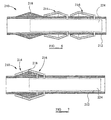
Figures 1 and 2 of the drawings in which there is shown diagrammatic plan and longitudinal cross-sectional views, respectively, of a downhole expandable seal, generally identified byreference numeral 10, in accordance with an embodiment of the present invention. Theseal 10, which is shown inFigures 1 and 2 in an unexpanded configuration, comprises a support member in the form of atubular body 12. Thetubular body 12 may be adapted to form part of a tubing string, such as a production tubing string. As will be described in further detail below, thedownhole seal 10 may be utilised as a packer to establish a seal in an annulus formed between thetubular body 12 and a wall of a wellbore. - The
seal 10 further comprises a deflectingportion 18 and first andsecond sealing portions tubular body 12, wherein the sealingportions portion 18. In the embodiment shown the first andsecond sealing portions tubular body 12, and the deflectingportion 18 is axially fixed relative to thetubular body 12. - The deflecting
portion 18 defines a double-ended conical shaped mandrel and comprises first and second cam surfaces 20, 22 adapted to be engaged by the first andsecond sealing portions second sealing portions portion 18 effects outward radial displacement of said sealingportions Figure 3 in which theseal 10 is shown in a partially expanded configuration. Respectivepiston drive assemblies Figures 2 and 3 , are provided for use in axially translating each sealingportion - Each sealing
assembly Figure 1 . In use, the axially extending members 14a, 16a of each sealingportion second sealing portions Figure 3 . - In the present embodiment, the sealing
portions portions portions Figure 4 , which shows theseal 10 in a fully expanded configuration. Accordingly, in use, radial expansion of thedownhole seal 10 may be achieved by the radial displacement of the sealingportions portion 18, in combination with swelling of the swellable material forming the sealingportions downhole seal 10 of the present invention may advantageously be employed, for example as a packer, in environments where a large expansion ratio is required, such as in situations where the intended location of the seal can only be accessed via passageways or conduits of restricted or reduced internal dimensions and profiles. - A downhole seal, generally identified by
reference numeral 110, in accordance with an alternative embodiment of the present invention is shown inFigure 5 . Theseal 110 is similar to seal 10 first shown inFigure 1 and as such like components share like reference numerals, incremented by 100. Thus, theseal 110 comprises atubular body 112 which supports a deflectingportion 118 and first andsecond sealing portions downhole seal 110 is similar to that ofseal 10 and as such no further explanation will be given. However, in the present embodiment the deflectingportion 118 is formed, at least partially, by a swelling material. In this respect theseal 110 is shown inFigure 5 in a fully expanded configuration, with the sealingportions portion 118 expanded by swelling of the swelling material. - In an alternative embodiment, which has not been illustrated, the sealing and deflecting portions may all comprise a swelling material.
- A further alternative embodiment of a downhole seal in accordance with the present invention is shown in
Figures 6 and 7 . The downhole seal, generally identified byreference numeral 210, is similar to theseal 10 first shown inFigure 1 and as such like features are identified by like reference numerals, incremented by 200. - In the present embodiment, the
downhole seal 210 comprises atubular body 210 which supports a deflectingportion 218 and first andsecond sealing portions seal 210 is in an unexpanded configuration, as shown inFigure 6 , the first andsecond sealing portions portion 218. Apiston drive assembly 224 is provided to axially translate both the sealingportions portion 218 to effect radial displacement of each sealingportion seal 210 is shown inFigure 7 in a partially extended configuration. In this respect one or all of the sealing and deflectingportions seal 210 into a fully expanded configuration. -
Figures 8 and 9 show another alternative embodiment of a downhole seal in accordance with the present invention. The downhole seal, in this case generally identified byreference numeral 310, is similar to theseal 10 first shown inFigure 1 and as such like features are identified by like reference numerals, incremented by 300. - The
seal 310 comprises atubular body 312 which supports a deflectingportion 318 in the form of a double-sided cone, and first andsecond sealing portions seal 10 is in an unexpanded configuration, as shown inFigure 8 , the sealingportions portion 318. In the present embodiment the sealingportions portion 318 bydrive assemblies portion 318 effects radial displacement of the sealingportions portions location 340, as shown inFigure 9 , in which theseal 310 is positioned in a partially expanded configuration. In a similar manner to the previous embodiments, one or more of the sealing and deflectingportions seal 310 into a fully expanded configuration. - Reference is now made to
Figures 10 and 11 in which there is shown a downhole seal, generally identified byreference numeral 410, in accordance with a further alternative embodiment of the present invention.Seal 410 is similar to seal 10 first shown inFigure 1 and as such like components share like reference numerals, incremented by 400. Theseal 410 is shown inFigure 10 in an unexpanded configuration and inFigure 11 in a partially expanded configuration. - In this embodiment the
seal 410 comprises atubular body 412 which supports a deflectingportion 418 and asingle sealing portion 414 in the form of a sleeve. In use, adrive assembly 424 translates the sealingportion 414 over the deflectingportion 418 to the configuration shown inFigure 11 . One or both of the sealingportion 314 and deflectingportion 318 comprises a swelling material which swells upon contact with a suitable activator to configure theseal 410 into a fully expanded configuration. - As described above, seals according to the present invention may be provided which are capable of achieving extremely large expansion rations, without compromising mechanical strength or sealing integrity. This is achieved by a combination of radially displacing one or more sealing portions by interacting with a deflecting member, and forming one or more components of the seal with a swelling material. Thus, a seal may be delivered through a small diameter conduit, channel, passage or the like and subsequently expanded into a significantly larger conduit, channel, passage or the like.
- It should be understood that the embodiments described above are merely exemplary and that various modifications may be made thereto without departing from the scope of the invention. For example, the seals may alternatively, or additionally, be utilised as an anchor. Furthermore, any number of sealing portions may be provided, and the sealing portions may be adapted to become radially stacked to effect expansion of the seal. Each sealing portion may be provided as a unitary component, or alternatively may comprise a number of individual components which may or may not be coupled together. Similarly, the deflecting member may be provided as a unitary component, or alternatively may comprise a number of individual components which may or may not be coupled together.
- Any suitable drive assembly, means or system may be utilised to axially translate the sealing portions.
- Furthermore, the sealing portion or portions of the seal may be at least partially covered by a further component or material, such as a rubber sleeve or the like, such that radial displacement of the sealing portions and swelling of the swelling material will move the cover into engagement with a bore wall or the like. The cover may assist in establishing and maintaining a seal. Also, the cover may assist to protect the other components of the seal, such as the sealing and deflecting portions.
Claims (15)
- An expandable downhole seal (10) comprising:a sealing portion (14) and a deflecting portion (18) adapted to move axially relative to each other to effect radial deflection of the sealing portion (14), wherein at least one of the sealing portion (14) and the deflecting portion (18) comprises a swelling material, and at least one of the sealing and deflecting portions (14, 18) comprises a cam surface (20) adapted to effect radial deflection of the sealing portion (14) upon relative axial movement of the sealing and deflecting portions (14, 18); anda support member (12) adapted to support the sealing portion (14) and deflecting portion (18).
- The expandable downhole seal (10) according to claim 1, wherein the sealing portion defines a first sealing portion (14) and the expandable downhole seal further comprises a second sealing portion (16), wherein relative axial movement of the first and second sealing portions (14, 16) and the deflecting portion (18) effects radial deflection of at least the first sealing portion (14).
- The expandable downhole seal (10) according to claim 2, wherein the first and second sealing portions (14, 16) are adapted to interengage.
- The expandable downhole seal (10) according to claim 3, wherein the first and second sealing portions (14, 16) are adapted to overlap each other in an axial direction.
- The expandable downhole seal (10) according to claim 3 or 4, wherein the first and second sealing portions (14, 16) comprise complementary interleaving features (14a, 16a) adapted to interleave each other.
- The expandable downhole seal (10) according to any one of claims 2 to 5, wherein at least one of the first and second sealing portions (14, 16) and the deflecting portion (18) is fixed relative to the support member (12), wherein movement of the remaining portions produce relative axial movement.
- The expandable downhole seal (10) according to any one of claims 2 to 6, wherein the first and second sealing portions (14, 16) are located on axially opposed sides of the deflecting portion (18), or wherein the first and second sealing portions (14, 16) are located on the same axial side of the deflecting member (18).
- The expandable downhole seal (10) according to any preceding claim, wherein the sealing portion (14) is adapted to directly engage the inner surface of a bore, or wherein the sealing portion (14) is adapted to indirectly engage the inner surface of a bore.
- The expandable downhole seal (10) according to any preceding claim, wherein one of the sealing and deflecting portions (14, 18) is fixed relative to the support member (12) and the other of the sealing and deflecting portions (14, 18) is axially moveable relative to the support member (12), or wherein both the sealing and deflecting portions (14, 18) are axially moveable relative to the support member (12).
- The expandable downhole seal (10) according to any preceding claim, wherein the sealing and deflecting portions (14, 18) are adapted to interengage upon relative axial movement thereof to overlap each other in an axial direction, wherein said interengagement effects radial deflection of the sealing portion (14).
- The expandable downhole seal (10) according to any preceding claim, wherein the deflecting portion (18) comprises a cam surface (20) adapted to radially displace the sealing portion (14).
- The expandable downhole seal (10) according to any preceding claim, wherein the sealing portion (14) comprises a unitary component, or wherein the sealing portion (14) comprises plurality of components which collectively define the sealing portion (14).
- The expandable downhole seal (10) according to any preceding claim, wherein relative axial movement of the sealing and deflecting portions (14, 18) in a reverse direction effects radial displacement of the sealing portion (14) in a direction to release or relax the seal, thus permitting the support member (12) to be withdrawn or moved to an alternative location.
- A method of establishing a seal within a wellbore, said method comprising the steps of:providing an expandable downhole seal (10) according to any preceding claim;running said downhole seal (10) into a well bore when in a first, unexpanded configuration;reconfiguring the downhole seal into a second, expanded configuration by effecting relative axial movement of the sealing portion (14) and the deflecting portion (18) to effect radial deflection of the sealing portion (14); andpermitting the swelling material to swell.
- The method according to claim 14, comprising the step of running the downhole seal (10) into a well bore filled with a material which does not initiate swelling of the swelling material and then displacing wellbore fluid with a swelling activator once the downhole seal (10) has reached or is approaching the desired location within the wellbore.
Applications Claiming Priority (2)
| Application Number | Priority Date | Filing Date | Title |
|---|---|---|---|
| GBGB0802237.8A GB0802237D0 (en) | 2008-02-07 | 2008-02-07 | Downhole seal |
| PCT/GB2009/000327 WO2009098465A1 (en) | 2008-02-07 | 2009-02-05 | Downhole seal |
Publications (2)
| Publication Number | Publication Date |
|---|---|
| EP2242897A1 EP2242897A1 (en) | 2010-10-27 |
| EP2242897B1 true EP2242897B1 (en) | 2011-08-10 |
Family
ID=39204378
Family Applications (1)
| Application Number | Title | Priority Date | Filing Date |
|---|---|---|---|
| EP09707363A Not-in-force EP2242897B1 (en) | 2008-02-07 | 2009-02-05 | Downhole seal |
Country Status (7)
| Country | Link |
|---|---|
| US (1) | US8727027B2 (en) |
| EP (1) | EP2242897B1 (en) |
| AT (1) | ATE519921T1 (en) |
| AU (1) | AU2009211179A1 (en) |
| CA (1) | CA2713653A1 (en) |
| GB (1) | GB0802237D0 (en) |
| WO (1) | WO2009098465A1 (en) |
Cited By (1)
| Publication number | Priority date | Publication date | Assignee | Title |
|---|---|---|---|---|
| CN110300835A (en) * | 2016-11-09 | 2019-10-01 | 匹克维尔系统私人有限公司 | Extend and collapse equipment and its application method |
Families Citing this family (10)
| Publication number | Priority date | Publication date | Assignee | Title |
|---|---|---|---|---|
| CA2856053A1 (en) * | 2011-11-18 | 2013-06-27 | Ruma Products Holding B.V. | Seal sleeve and assembly including such a seal sleeve |
| NL2007896C2 (en) * | 2011-11-30 | 2013-06-03 | Ruma Products Holding B V | Seal sleeve and assembly including such a seal sleeve. |
| US8973667B2 (en) * | 2012-01-18 | 2015-03-10 | Baker Hughes Incorporated | Packing element with full mechanical circumferential support |
| WO2015126419A1 (en) | 2014-02-24 | 2015-08-27 | Halliburton Energy Services, Inc. | Propping subterranean formation fractures using memory particulates |
| GB201405009D0 (en) * | 2014-03-20 | 2014-05-07 | Xtreme Innovations Ltd | Seal arrangement |
| WO2015156796A1 (en) * | 2014-04-09 | 2015-10-15 | Halliburton Energy Services, Inc | Sealing element for downhole tool |
| US9506315B2 (en) * | 2015-03-06 | 2016-11-29 | Team Oil Tools, Lp | Open-hole packer |
| WO2016186643A1 (en) * | 2015-05-18 | 2016-11-24 | Halliburton Energy Services Inc. | Expandable seal |
| CN116398082B (en) * | 2023-06-07 | 2023-09-05 | 太原理工大学 | Multi-aquifer packing device, water taking device and water taking method for deep geothermal well |
| CN116816298B (en) * | 2023-07-19 | 2024-03-19 | 德州地平线石油科技股份有限公司 | High-temperature high-pressure corrosion-resistant expansion metal framework rubber cylinder and processing equipment thereof |
Family Cites Families (8)
| Publication number | Priority date | Publication date | Assignee | Title |
|---|---|---|---|---|
| US6772844B2 (en) | 2001-10-30 | 2004-08-10 | Smith International, Inc. | High pressure sealing apparatus and method |
| US6854522B2 (en) * | 2002-09-23 | 2005-02-15 | Halliburton Energy Services, Inc. | Annular isolators for expandable tubulars in wellbores |
| US6834725B2 (en) * | 2002-12-12 | 2004-12-28 | Weatherford/Lamb, Inc. | Reinforced swelling elastomer seal element on expandable tubular |
| GB0317547D0 (en) * | 2003-07-26 | 2003-08-27 | Weatherford Lamb | Sealing tubing |
| WO2005052308A1 (en) * | 2003-11-25 | 2005-06-09 | Baker Hughes Incorporated | Swelling layer inflatable |
| AU2005266956B2 (en) | 2004-07-23 | 2011-01-20 | Baker Hughes Incorporated | Open hole expandable patch |
| US7387158B2 (en) * | 2006-01-18 | 2008-06-17 | Baker Hughes Incorporated | Self energized packer |
| US8550178B2 (en) * | 2011-03-09 | 2013-10-08 | Baker Hughes Incorporated | Expandable isolation packer |
-
2008
- 2008-02-07 GB GBGB0802237.8A patent/GB0802237D0/en not_active Ceased
-
2009
- 2009-02-05 EP EP09707363A patent/EP2242897B1/en not_active Not-in-force
- 2009-02-05 AU AU2009211179A patent/AU2009211179A1/en not_active Abandoned
- 2009-02-05 US US12/865,981 patent/US8727027B2/en active Active
- 2009-02-05 WO PCT/GB2009/000327 patent/WO2009098465A1/en active Application Filing
- 2009-02-05 AT AT09707363T patent/ATE519921T1/en not_active IP Right Cessation
- 2009-02-05 CA CA2713653A patent/CA2713653A1/en not_active Abandoned
Cited By (1)
| Publication number | Priority date | Publication date | Assignee | Title |
|---|---|---|---|---|
| CN110300835A (en) * | 2016-11-09 | 2019-10-01 | 匹克维尔系统私人有限公司 | Extend and collapse equipment and its application method |
Also Published As
| Publication number | Publication date |
|---|---|
| WO2009098465A1 (en) | 2009-08-13 |
| AU2009211179A1 (en) | 2009-08-13 |
| EP2242897A1 (en) | 2010-10-27 |
| CA2713653A1 (en) | 2009-08-13 |
| US20110193291A1 (en) | 2011-08-11 |
| US8727027B2 (en) | 2014-05-20 |
| GB0802237D0 (en) | 2008-03-12 |
| ATE519921T1 (en) | 2011-08-15 |
Similar Documents
| Publication | Publication Date | Title |
|---|---|---|
| EP2242897B1 (en) | Downhole seal | |
| EP3519667B1 (en) | Downhole packer element with propped element spacer | |
| US7422058B2 (en) | Reinforced open-hole zonal isolation packer and method of use | |
| EP1753936B1 (en) | Sealing system | |
| US8083001B2 (en) | Expandable gage ring | |
| US7823636B2 (en) | Packer | |
| EP2246522B1 (en) | Improvements to swellable apparatus | |
| AU2022209205A1 (en) | Expanding and collapsing apparatus and methods of use | |
| GB2432600A (en) | Anchoring system | |
| EP3119982A1 (en) | Seal arrangement | |
| US20150211323A1 (en) | Sealing apparatus and method | |
| CA2842065C (en) | Apparatus and method of zonal isolation in a wellbore using expandable packers | |
| US20160168943A1 (en) | Downhole seal | |
| US11542775B2 (en) | Anti-extrusion assembly and a sealing system comprising same |
Legal Events
| Date | Code | Title | Description |
|---|---|---|---|
| PUAI | Public reference made under article 153(3) epc to a published international application that has entered the european phase |
Free format text: ORIGINAL CODE: 0009012 |
|
| 17P | Request for examination filed |
Effective date: 20100728 |
|
| AK | Designated contracting states |
Kind code of ref document: A1 Designated state(s): AT BE BG CH CY CZ DE DK EE ES FI FR GB GR HR HU IE IS IT LI LT LU LV MC MK MT NL NO PL PT RO SE SI SK TR |
|
| AX | Request for extension of the european patent |
Extension state: AL BA RS |
|
| GRAP | Despatch of communication of intention to grant a patent |
Free format text: ORIGINAL CODE: EPIDOSNIGR1 |
|
| DAX | Request for extension of the european patent (deleted) | ||
| GRAS | Grant fee paid |
Free format text: ORIGINAL CODE: EPIDOSNIGR3 |
|
| GRAA | (expected) grant |
Free format text: ORIGINAL CODE: 0009210 |
|
| AK | Designated contracting states |
Kind code of ref document: B1 Designated state(s): AT BE BG CH CY CZ DE DK EE ES FI FR GB GR HR HU IE IS IT LI LT LU LV MC MK MT NL NO PL PT RO SE SI SK TR |
|
| REG | Reference to a national code |
Ref country code: GB Ref legal event code: FG4D |
|
| REG | Reference to a national code |
Ref country code: CH Ref legal event code: EP |
|
| REG | Reference to a national code |
Ref country code: IE Ref legal event code: FG4D |
|
| REG | Reference to a national code |
Ref country code: DE Ref legal event code: R096 Ref document number: 602009002102 Country of ref document: DE Effective date: 20111020 |
|
| REG | Reference to a national code |
Ref country code: NL Ref legal event code: VDEP Effective date: 20110810 |
|
| REG | Reference to a national code |
Ref country code: NO Ref legal event code: T2 Effective date: 20110810 |
|
| LTIE | Lt: invalidation of european patent or patent extension |
Effective date: 20110810 |
|
| PG25 | Lapsed in a contracting state [announced via postgrant information from national office to epo] |
Ref country code: IS Free format text: LAPSE BECAUSE OF FAILURE TO SUBMIT A TRANSLATION OF THE DESCRIPTION OR TO PAY THE FEE WITHIN THE PRESCRIBED TIME-LIMIT Effective date: 20111210 Ref country code: FI Free format text: LAPSE BECAUSE OF FAILURE TO SUBMIT A TRANSLATION OF THE DESCRIPTION OR TO PAY THE FEE WITHIN THE PRESCRIBED TIME-LIMIT Effective date: 20110810 Ref country code: NL Free format text: LAPSE BECAUSE OF FAILURE TO SUBMIT A TRANSLATION OF THE DESCRIPTION OR TO PAY THE FEE WITHIN THE PRESCRIBED TIME-LIMIT Effective date: 20110810 Ref country code: PT Free format text: LAPSE BECAUSE OF FAILURE TO SUBMIT A TRANSLATION OF THE DESCRIPTION OR TO PAY THE FEE WITHIN THE PRESCRIBED TIME-LIMIT Effective date: 20111212 Ref country code: HR Free format text: LAPSE BECAUSE OF FAILURE TO SUBMIT A TRANSLATION OF THE DESCRIPTION OR TO PAY THE FEE WITHIN THE PRESCRIBED TIME-LIMIT Effective date: 20110810 Ref country code: SE Free format text: LAPSE BECAUSE OF FAILURE TO SUBMIT A TRANSLATION OF THE DESCRIPTION OR TO PAY THE FEE WITHIN THE PRESCRIBED TIME-LIMIT Effective date: 20110810 Ref country code: LT Free format text: LAPSE BECAUSE OF FAILURE TO SUBMIT A TRANSLATION OF THE DESCRIPTION OR TO PAY THE FEE WITHIN THE PRESCRIBED TIME-LIMIT Effective date: 20110810 |
|
| REG | Reference to a national code |
Ref country code: AT Ref legal event code: MK05 Ref document number: 519921 Country of ref document: AT Kind code of ref document: T Effective date: 20110810 |
|
| PG25 | Lapsed in a contracting state [announced via postgrant information from national office to epo] |
Ref country code: LV Free format text: LAPSE BECAUSE OF FAILURE TO SUBMIT A TRANSLATION OF THE DESCRIPTION OR TO PAY THE FEE WITHIN THE PRESCRIBED TIME-LIMIT Effective date: 20110810 Ref country code: CY Free format text: LAPSE BECAUSE OF FAILURE TO SUBMIT A TRANSLATION OF THE DESCRIPTION OR TO PAY THE FEE WITHIN THE PRESCRIBED TIME-LIMIT Effective date: 20110810 Ref country code: GR Free format text: LAPSE BECAUSE OF FAILURE TO SUBMIT A TRANSLATION OF THE DESCRIPTION OR TO PAY THE FEE WITHIN THE PRESCRIBED TIME-LIMIT Effective date: 20111111 Ref country code: SI Free format text: LAPSE BECAUSE OF FAILURE TO SUBMIT A TRANSLATION OF THE DESCRIPTION OR TO PAY THE FEE WITHIN THE PRESCRIBED TIME-LIMIT Effective date: 20110810 Ref country code: PL Free format text: LAPSE BECAUSE OF FAILURE TO SUBMIT A TRANSLATION OF THE DESCRIPTION OR TO PAY THE FEE WITHIN THE PRESCRIBED TIME-LIMIT Effective date: 20110810 Ref country code: AT Free format text: LAPSE BECAUSE OF FAILURE TO SUBMIT A TRANSLATION OF THE DESCRIPTION OR TO PAY THE FEE WITHIN THE PRESCRIBED TIME-LIMIT Effective date: 20110810 |
|
| PG25 | Lapsed in a contracting state [announced via postgrant information from national office to epo] |
Ref country code: BE Free format text: LAPSE BECAUSE OF FAILURE TO SUBMIT A TRANSLATION OF THE DESCRIPTION OR TO PAY THE FEE WITHIN THE PRESCRIBED TIME-LIMIT Effective date: 20110810 |
|
| PG25 | Lapsed in a contracting state [announced via postgrant information from national office to epo] |
Ref country code: CZ Free format text: LAPSE BECAUSE OF FAILURE TO SUBMIT A TRANSLATION OF THE DESCRIPTION OR TO PAY THE FEE WITHIN THE PRESCRIBED TIME-LIMIT Effective date: 20110810 Ref country code: SK Free format text: LAPSE BECAUSE OF FAILURE TO SUBMIT A TRANSLATION OF THE DESCRIPTION OR TO PAY THE FEE WITHIN THE PRESCRIBED TIME-LIMIT Effective date: 20110810 |
|
| PGFP | Annual fee paid to national office [announced via postgrant information from national office to epo] |
Ref country code: NO Payment date: 20120210 Year of fee payment: 4 |
|
| PG25 | Lapsed in a contracting state [announced via postgrant information from national office to epo] |
Ref country code: RO Free format text: LAPSE BECAUSE OF FAILURE TO SUBMIT A TRANSLATION OF THE DESCRIPTION OR TO PAY THE FEE WITHIN THE PRESCRIBED TIME-LIMIT Effective date: 20110810 Ref country code: IT Free format text: LAPSE BECAUSE OF FAILURE TO SUBMIT A TRANSLATION OF THE DESCRIPTION OR TO PAY THE FEE WITHIN THE PRESCRIBED TIME-LIMIT Effective date: 20110810 Ref country code: EE Free format text: LAPSE BECAUSE OF FAILURE TO SUBMIT A TRANSLATION OF THE DESCRIPTION OR TO PAY THE FEE WITHIN THE PRESCRIBED TIME-LIMIT Effective date: 20110810 |
|
| PLBE | No opposition filed within time limit |
Free format text: ORIGINAL CODE: 0009261 |
|
| STAA | Information on the status of an ep patent application or granted ep patent |
Free format text: STATUS: NO OPPOSITION FILED WITHIN TIME LIMIT |
|
| PG25 | Lapsed in a contracting state [announced via postgrant information from national office to epo] |
Ref country code: DK Free format text: LAPSE BECAUSE OF FAILURE TO SUBMIT A TRANSLATION OF THE DESCRIPTION OR TO PAY THE FEE WITHIN THE PRESCRIBED TIME-LIMIT Effective date: 20110810 |
|
| 26N | No opposition filed |
Effective date: 20120511 |
|
| REG | Reference to a national code |
Ref country code: DE Ref legal event code: R097 Ref document number: 602009002102 Country of ref document: DE Effective date: 20120511 |
|
| PG25 | Lapsed in a contracting state [announced via postgrant information from national office to epo] |
Ref country code: MC Free format text: LAPSE BECAUSE OF NON-PAYMENT OF DUE FEES Effective date: 20120229 |
|
| REG | Reference to a national code |
Ref country code: IE Ref legal event code: MM4A |
|
| REG | Reference to a national code |
Ref country code: FR Ref legal event code: ST Effective date: 20121031 |
|
| REG | Reference to a national code |
Ref country code: DE Ref legal event code: R119 Ref document number: 602009002102 Country of ref document: DE Effective date: 20120901 |
|
| PG25 | Lapsed in a contracting state [announced via postgrant information from national office to epo] |
Ref country code: FR Free format text: LAPSE BECAUSE OF NON-PAYMENT OF DUE FEES Effective date: 20120229 Ref country code: IE Free format text: LAPSE BECAUSE OF NON-PAYMENT OF DUE FEES Effective date: 20120205 |
|
| PG25 | Lapsed in a contracting state [announced via postgrant information from national office to epo] |
Ref country code: MK Free format text: LAPSE BECAUSE OF FAILURE TO SUBMIT A TRANSLATION OF THE DESCRIPTION OR TO PAY THE FEE WITHIN THE PRESCRIBED TIME-LIMIT Effective date: 20110810 |
|
| PG25 | Lapsed in a contracting state [announced via postgrant information from national office to epo] |
Ref country code: ES Free format text: LAPSE BECAUSE OF FAILURE TO SUBMIT A TRANSLATION OF THE DESCRIPTION OR TO PAY THE FEE WITHIN THE PRESCRIBED TIME-LIMIT Effective date: 20111121 |
|
| PG25 | Lapsed in a contracting state [announced via postgrant information from national office to epo] |
Ref country code: DE Free format text: LAPSE BECAUSE OF NON-PAYMENT OF DUE FEES Effective date: 20120901 Ref country code: BG Free format text: LAPSE BECAUSE OF FAILURE TO SUBMIT A TRANSLATION OF THE DESCRIPTION OR TO PAY THE FEE WITHIN THE PRESCRIBED TIME-LIMIT Effective date: 20111110 |
|
| PG25 | Lapsed in a contracting state [announced via postgrant information from national office to epo] |
Ref country code: MT Free format text: LAPSE BECAUSE OF FAILURE TO SUBMIT A TRANSLATION OF THE DESCRIPTION OR TO PAY THE FEE WITHIN THE PRESCRIBED TIME-LIMIT Effective date: 20110810 |
|
| REG | Reference to a national code |
Ref country code: CH Ref legal event code: PL |
|
| PG25 | Lapsed in a contracting state [announced via postgrant information from national office to epo] |
Ref country code: CH Free format text: LAPSE BECAUSE OF NON-PAYMENT OF DUE FEES Effective date: 20130228 Ref country code: NO Free format text: LAPSE BECAUSE OF NON-PAYMENT OF DUE FEES Effective date: 20130228 Ref country code: LI Free format text: LAPSE BECAUSE OF NON-PAYMENT OF DUE FEES Effective date: 20130228 |
|
| PG25 | Lapsed in a contracting state [announced via postgrant information from national office to epo] |
Ref country code: TR Free format text: LAPSE BECAUSE OF FAILURE TO SUBMIT A TRANSLATION OF THE DESCRIPTION OR TO PAY THE FEE WITHIN THE PRESCRIBED TIME-LIMIT Effective date: 20110810 |
|
| PG25 | Lapsed in a contracting state [announced via postgrant information from national office to epo] |
Ref country code: LU Free format text: LAPSE BECAUSE OF NON-PAYMENT OF DUE FEES Effective date: 20120205 |
|
| PG25 | Lapsed in a contracting state [announced via postgrant information from national office to epo] |
Ref country code: HU Free format text: LAPSE BECAUSE OF FAILURE TO SUBMIT A TRANSLATION OF THE DESCRIPTION OR TO PAY THE FEE WITHIN THE PRESCRIBED TIME-LIMIT Effective date: 20090205 |
|
| PGFP | Annual fee paid to national office [announced via postgrant information from national office to epo] |
Ref country code: GB Payment date: 20150204 Year of fee payment: 7 |
|
| GBPC | Gb: european patent ceased through non-payment of renewal fee |
Effective date: 20160205 |
|
| PG25 | Lapsed in a contracting state [announced via postgrant information from national office to epo] |
Ref country code: GB Free format text: LAPSE BECAUSE OF NON-PAYMENT OF DUE FEES Effective date: 20160205 |