EP1753689B1 - Aufzugsanordnung - Google Patents
Aufzugsanordnung Download PDFInfo
- Publication number
- EP1753689B1 EP1753689B1 EP05740952A EP05740952A EP1753689B1 EP 1753689 B1 EP1753689 B1 EP 1753689B1 EP 05740952 A EP05740952 A EP 05740952A EP 05740952 A EP05740952 A EP 05740952A EP 1753689 B1 EP1753689 B1 EP 1753689B1
- Authority
- EP
- European Patent Office
- Prior art keywords
- elevator
- elevator car
- toe guard
- safety circuit
- safety
- Prior art date
- Legal status (The legal status is an assumption and is not a legal conclusion. Google has not performed a legal analysis and makes no representation as to the accuracy of the status listed.)
- Expired - Lifetime
Links
Images


Classifications
-
- B—PERFORMING OPERATIONS; TRANSPORTING
- B66—HOISTING; LIFTING; HAULING
- B66B—ELEVATORS; ESCALATORS OR MOVING WALKWAYS
- B66B13/00—Doors, gates, or other apparatus controlling access to, or exit from, cages or lift well landings
- B66B13/24—Safety devices in passenger lifts, not otherwise provided for, for preventing trapping of passengers
- B66B13/28—Safety devices in passenger lifts, not otherwise provided for, for preventing trapping of passengers between car or cage and wells
- B66B13/285—Toe guards or apron devices
Definitions
- the present invention relates to an arrangement as presented in the preamble of claim 1 concerning a safety device for an elevator door opening.
- a safety device used in an elevator door opening is a foot guard, also called a toe guard, placed at the lower edge of the elevator car and having a length substantially at least equal to the width of the landing door opening.
- the toe guard is a plate-like piece or equivalent mounted in a substantially vertical plane, and it is designed to block the gap opening into the elevator shaft between the lower edge of the elevator and the floor surface of the landing e.g. when the elevator has stopped due to a failure so that the lower edge of the elevator car remains above the surface of the landing floor. This gap may be so large that a person escaping from the elevator can fall through the gap into the elevator shaft when descending from the car remaining above the surface of the landing floor.
- the safety circuit of the toe guard has to be bypassed to allow the drive current to be supplied to the elevator even in such a case.
- the safety circuit also needs to be bypassed in a repair or maintenance situation where the elevator car has to be driven to a level below the lowest landing floor, e.g. down to the buffers. In these situations, however, it must be made sure that the toe guard will return to its normal position after the elevator car has moved upwards from the lowest level.
- One further problem is to bypass the elevator's safety circuit in a way allowing the toe guard to work well as a protective element by stopping the movement of the elevator car if the toe guard hits an obstacle, such as a person's hand, foot or body, but at the same time so that the toe guard will not stop the elevator car when the elevator descends to the lowest level in a shaft with a low pit.
- FIG. 4 and 5 show a solution in which the structure comprises a telescoping toe guard with an external lower part moving vertically on a fixed internal upper part.
- a problem with the solution described in this specification is dirt, which can easily get into the open spaces between the moving parts, causing operational disturbances.
- This solution too, has the drawback that it does not propose any kind of safety circuit, so there is not necessarily anything to stop the elevator when the toe guard hits an obstacle.
- the object of the present invention is to overcome the above-mentioned drawbacks and to achieve a reliably functioning safety device arrangement of economical cost for the door opening of an elevator, such as a toe guard connected to the elevator safety circuit so that, when the toe guard meets the bottom of a low elevator shaft, the safety circuit of the toe guard will not disconnect the supply of current to the elevator.
- the safety device arrangement of the invention is characterized by what is disclosed in the characterization part of claim 1.
- Other embodiments of the invention are characterized by what is disclosed in the other claims.
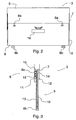
- Fig. 1 presents a diagrammatic and simplified view of an elevator car 2 having stopped in the elevator shaft 1 at a position somewhat above the lowest landing floor 4.
- the gap opening into the elevator shaft between the lower edge of the elevator car and the landing floor 4 is covered by telescoping toe guard 3 extending downwards from the front edge of the elevator car 2 and having a total height larger than the height of the pit 5 of the elevator shaft.
- Fig. 1 also shows a safety circuit bypass breaker 17, depicted with broken lines and, in this embodiment, fastened to the lower part of the elevator car 2.
- the bypass breaker is controlled by a ramp 18 mounted on a side wall of the shaft 1.
- Figures 2 and 3 present a toe guard 3 according to the invention as seen from behind, i.e. from the direction of the elevator shaft, and from one side and partially sectioned.
- An upper part 6 fixedly attached to the front edge of the elevator car 2 extends directly downwards from the front edge of the elevator car.
- At the lower edge of the planar front plate 11 of the upper part 6 is a fold turned obliquely inwards, i.e. towards the lower part 9.
- the side edges of the upper part 6 have folds turned inwards substantially perpendicularly to the front plate 11 to form the side walls 12 of the upper part 6.
- Provided on the inner surface of the side walls 12 are substantially vertical guides 7 for guiding the vertical motion of the lower part 9.
- the lower edge of the lower part 9 is provided with one or more buffers 8b serving to dampen the impact on the lower part 9 when the lower part hits the bottom of the elevator shaft.
- the inner surface of the lower part 6 is additionally provided with a safety circuit breaker 16, the counterpart of which is placed in the upper part of the outer surface of the lower part 9.
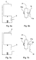
- FIGS 4a-7b give a more detailed illustration of the connection of the safety circuit 21 of the toe guard 3 with the elevator car 2 at different heights. If the pit 5 of the elevator shaft is lower than the height of the toe guard 3 in the normal position, then the lower part 9 of the telescoping toe guard 3 is pushed upwards into the upper part 6 when the elevator car 2 comes to the lowest landing floor and the contact 16a of the breaker 16 of the safety circuit 21 opens. In this situation, however, the open contact 16a must not produce a failure situation or cause the current to be switched off, so there is a separate bypass breaker 17 fitted in the safety circuit 21. The contact 17a of the bypass breaker bypasses the contact 16a of the safety circuit 21 when the elevator car 2 is at the lowest landing floor 4.
- Figures 4a and 4b represent the aforesaid situation at the lowest landing floor 4.
- the elevator car 2 has descended to the lowest landing floor 4 and, due to the low pit, the lower part 9 of the toe guard 3 has been pushed upwards into the upper part 6.
- Fig. 4b shows that the contact 16a of the safety circuit breaker 16 has opened, but as the bypass breaker 17 is in its normal position below the ramp 18, the contact 17a of the bypass breaker 17 is closed and bypasses the safety circuit 21 so that the elevator receives its normal operating current and no failure situation occurs.
- figures 5a and 5b represent a situation where the elevator car 2 has just started moving upwards from the lowest landing floor 4 and the lower part 9 of the toe guard 3 is stuck inside the upper part 6 and has not come down to its normal position as it should have.
- the contact 16a of the breaker 16 of the safety circuit 21 remains in the open position and, as the bypass breaker 17 has met the ramp 18, contact 17a has also opened, so the safety circuit 21 has switched off the supply of operating current to the elevator and the elevator car 2 has stopped in consequence of the failure situation.
- Figures 7a and 7b represent a normal situation when the elevator car 2 is at any position in the elevator shaft 1 so that the bypass breaker 17 is above the ramp 18.
- the lower part 9 of the toe guard 3 is in its normal low position, the contact 16a of the safety circuit breaker 16 is closed and likewise the contact 17a of the bypass breaker 17 is closed, so the safety circuit 21 allows the flow of operating current via contact 16a and the elevator car 2 moves normally.
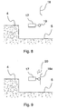
- Fig. 8 presents a more detailed illustration of the bypass breaker 17 of the elevator safety circuit 21.
- the bypass breaker is provided with a roller-like follower element 19 placed at the end of a lever arm.
- the bypass breaker 17 is mounted on the lower part of the elevator car 2, e.g. on the side of the elevator car.
- a ramp 18 attached to the wall of the elevator shaft at the lowest floor level 4 or close to it is a ramp 18 serving as a counterpart of the bypass breaker 17 and consisting of e.g. a plate rail extending towards the elevator car 2 from the shaft wall.
- the upper and lower parts of the ramp are in an inclined position to allow the passage of the roller-like follower element 19, whereas the middle part of the ramp is in a substantially vertical position.
- the vertical distance of the lower part of the ramp 18 from the bypass breaker 17 in its low position and the length of the middle part of the ramp are so designed that the elevator car 2 can not be accelerated to a speed high enough to prevent the elevator car in a failure situation from stopping at the ramp 18 when the roller-like follower element 19 meets the ramp 18.
- a suitable vertical distance with the commonly used elevator car speeds is e.g. in the range of 350 - 700 mm, and a suitable length of the middle part of the ramp 18 is e.g. about 1000 mm.
- Positive opening of the contact 17a is implemented using an oblique counterelement 20 placed in the elevator shaft above the ramp 18a so that, as the elevator car 2 is moving upwards, the roller-like follower element 19 will meet the counterelement 20 after leaving the ramp 18a and follow the lower surface of the counterelement 20, positively pulling the contact 17a into the open position.
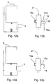
- the mechanism for positive opening operation of the contact 17a can also be seen in figures 10b, 11 and 12b below.
- Figures 10a and 10b represent a situation with the elevator car at the lowest landing floor 4.
- the elevator car 2 has descended to the lowest landing floor 4 and, due to the low pit, the lower part 9 of the toe guard 3 has been pushed upwards into the upper part 6.
- Fig. 10b shows that the contact 16a of the safety circuit breaker 16 has opened, but because the bypass breaker 17 is in an activated state as it is on the ramp 18a, the contact 17a of the bypass breaker 17 is closed and bypasses the safety circuit 21 so that the elevator receives its normal operating current and no failure situation occurs.
- figures 11a and 11b represent a situation where the elevator car 2 has just started moving upwards from the lowest landing floor 4 and the lower part 9 of the toe guard 3 is stuck inside the upper part 6 and has not come down to its normal position as it should have.
- the contact 16a of the breaker 16 of the safety circuit 21 remains in the open position and, as the bypass breaker 17 has left the ramp 18, contact 17a has also been opened by positive control, assisted by the counterelement 20, so the safety circuit 21 has switched off the supply of operating current to the elevator and the elevator car 2 has stopped in consequence of the failure situation.
- Figures 12a and 12b represent a situation corresponding to figures 11a and 11b when the lower part 9 of the toe guard 3 has come down to its normal low position after the departure of the elevator car 2.
- the contact 16a of the safety circuit breaker 16 has closed and, after the roller-like follower element 19 has left the ramp 18a, contact 17a has been opened by positive control assisted by the counterelement 20, but the safety circuit 21 still allows the flow of operating current via contact 16a and the elevator car 2 continues its upward movement in the normal way.
- Figures 13a and 13b represent a normal situation when the elevator car 2 is at any position in the elevator shaft 1 so that the bypass breaker 17 is above the ramp 18a.
- the lower part 9 of the toe guard 3 is in its normal low position, the contact 16a of the safety circuit breaker 16 is closed and the contact 17a of the bypass breaker 17 is open, so the safety circuit 21 allows the flow of operating current via contact 16a and the elevator car 2 moves normally.
- the embodiment presented in figures 9-13b have the advantage that the safety circuit 21 switches off the supply of operating current to the elevator even in situations where an obstacle having got in the way of the toe guard 3 lifts the lower part 9 of the toe guard 3 into the upper part 6 when the elevator car 2 is at any other position in the elevator shaft than at the lowest landing floor 4.
- the toe guard may also be made from more than two telescoping parts.
- a safe toe guard can be made from two or more parts placed side by side which move into their respective upper parts in such manner that only that part moves to which a force is applied from below. This provides the advantage that the opening leading into the shaft remains as well closed as possible, because only a relatively narrow part of the toe guard slides upwards.
- bypass breaker 17 may be placed e.g. in the upper part of the elevator car or it may also be mounted in the elevator shaft. In this case, the counterpart 18, 18a also has to be placed correspondingly.
Landscapes
- Cage And Drive Apparatuses For Elevators (AREA)
- Types And Forms Of Lifts (AREA)
- Lift-Guide Devices, And Elevator Ropes And Cables (AREA)
- Maintenance And Inspection Apparatuses For Elevators (AREA)
- Elevator Door Apparatuses (AREA)
- Elevator Control (AREA)
Claims (5)
- Sicherheitsanordnung für eine Aufzugstüröffnung, welche Sicherheitsanordnung wenigstens einen im Wesentlichen an der Unterkante der Aufzugskabine angeordneten Zehenschutz (3)und einen mit dem Aufzugssystem verbundenen Sicherheitskreislauf (21) und einen an dem Zehenschutz (3) angeordneten Schalter (16) des Sicherheitskreises (21) und einen mit dem Sicherheitskreis (21) verbundenen Nebenschlussschalter (17) aufweist, welcher Nebenschlussschalter geeignet ist, den Schalter (16) des Sicherheitskreises zu überbrücken, zumindest wenn sich der Aufzug an oder nahe dem untersten Stockwerk befindet, dadurch gekennzeichnet, dass der der Zehenschutz einen oberen Teil (6) und einen unteren Teil (9) umfasst, welcher sich in teleskopischer Art relativ zum oberen Teil bewegt, welcher untere Teil (9) konzipiert ist, nach oben in den oberen Teil (6) hineinzugleiten, wenn er auf einen Widerstand trifft, und dass der Sicherheitskreisschalter (16) der in dem Zehenschutz (3) enthalten ist dazu konzipiert ist, den Sicherheitskreis (21) zu öffnen, wenn sich der untere Teil (9) relativ zum oberen Teil (6) bewegt.
- Sicherheitsanordnung nach Anspruch 1, dadurch gekennzeichnet, dass zwischen dem oberen Teil (6) und dem unteren Teil (9) ein Sicherheitskreisschalter (16) angeordnet ist, der zusammen mit dem Nebenschlussschalter (17) mit dem Sicherheitskreis (21) des Aufzugs derart verbunden ist, dass wenn der untere Teil (9) des Zehenschutzes (3) sich nach oben in den oberen Teil (6) bewegt, der Sicherheitsschaltkreis (21) die Bewegung der Aufzugskabine (2) ausgenommen am untersten Stockwerk stoppt.
- Sicherheitsanordnung nach einem der vorhergehenden Ansprüche, dadurch gekennzeichnet, dass der Nebenschlussschalter (17) an der Aufzugskabine (2) angeordnet ist, und dass das Gegenstück (18, 18a) des Nebenschlussschalters (17) an der Wand des Aufzugschachtes am oder nahe dem untersten Stockwerk angeordnet ist.
- Sicherheitsanordnung nach einem der Ansprüche 1 - 2, dadurch gekennzeichnet, dass der Nebenschlussschalter (17) an dem unteren Teil der Aufzugskabine (2) angeordnet ist, und dass das Gegenstück (18, 18a) des Nebenschlussschalters (17) an der Wand des Aufzugsschachtes an oder nahe dem untersten Stockwerk angeordnet ist.
- Sicherheitsanordnung nach einem der Ansprüche 1 - 2, dadurch gekennzeichnet, dass der Nebenschlussschalter (17) an der Wand des Aufzugsschachtes an oder nahe dem untersten Stockwerk angeordnet ist, und dass das Gegenstück (18, 18a) des Nebenschlussschalters (17) an der Aufzugskabine (2) angeordnet ist.
Applications Claiming Priority (2)
| Application Number | Priority Date | Filing Date | Title |
|---|---|---|---|
| FI20040777A FI118220B (fi) | 2004-06-07 | 2004-06-07 | Hissin oviaukon turvajärjestely |
| PCT/FI2005/000229 WO2005121015A2 (en) | 2004-06-07 | 2005-05-18 | Elevator arrangement |
Publications (2)
| Publication Number | Publication Date |
|---|---|
| EP1753689A2 EP1753689A2 (de) | 2007-02-21 |
| EP1753689B1 true EP1753689B1 (de) | 2008-06-04 |
Family
ID=32524457
Family Applications (1)
| Application Number | Title | Priority Date | Filing Date |
|---|---|---|---|
| EP05740952A Expired - Lifetime EP1753689B1 (de) | 2004-06-07 | 2005-05-18 | Aufzugsanordnung |
Country Status (9)
| Country | Link |
|---|---|
| US (1) | US7350627B2 (de) |
| EP (1) | EP1753689B1 (de) |
| CN (1) | CN100554124C (de) |
| AT (1) | ATE397564T1 (de) |
| DE (1) | DE602005007348D1 (de) |
| ES (1) | ES2304700T3 (de) |
| FI (1) | FI118220B (de) |
| NO (1) | NO20065729L (de) |
| WO (1) | WO2005121015A2 (de) |
Cited By (2)
| Publication number | Priority date | Publication date | Assignee | Title |
|---|---|---|---|---|
| US11136222B2 (en) | 2018-07-26 | 2021-10-05 | Otis Elevator Company | Elevator car apron |
| US11161716B2 (en) | 2018-02-23 | 2021-11-02 | Otis Elevator Company | Elevator car toe guard system |
Families Citing this family (20)
| Publication number | Priority date | Publication date | Assignee | Title |
|---|---|---|---|---|
| EP1730068B1 (de) * | 2004-03-09 | 2010-05-19 | Otis Elevator Company | Kabinenschürze für aufzug |
| DE102006022407B3 (de) | 2006-05-13 | 2007-08-23 | W & W Aufzugs- Und Industriekomponenten Gmbh & Co. Kg | Dreiteilige Teleskop-Fahrkorbschürze |
| EP2035313B1 (de) | 2006-06-30 | 2010-11-03 | Otis Elevator Company | Sicherheitsvorrichtung zur sicherung von mindesträumen am oberen oder unteren ende eines gerade inspizierten aufzugschachts und aufzug mit solchen sicherheitsvorrichtungen |
| EP2035315B1 (de) | 2006-06-30 | 2012-09-05 | Otis Elevator Company | Aufzug mit flachem schacht und/oder einem niedrigen schachtkopf |
| FI119021B (fi) * | 2006-12-19 | 2008-06-30 | Kone Corp | Varvassuojus hissin koria varten |
| ES2350410T3 (es) | 2007-09-12 | 2011-01-21 | W+W Aufzugkomponenten Gmbh U. Co. Kg | Cabina de ascensor. |
| FI121423B (fi) * | 2009-04-23 | 2010-11-15 | Kone Corp | Hissin turvajärjestely |
| US8469155B2 (en) * | 2011-02-16 | 2013-06-25 | Vertical Motion Innovations, Llc | Elevator life safety gate |
| JP5796124B2 (ja) | 2011-03-22 | 2015-10-21 | オーチス エレベータ カンパニーOtis Elevator Company | エレベータ装置のトーガードアセンブリ |
| CN103443011B (zh) | 2011-04-05 | 2015-12-16 | 奥的斯电梯公司 | 用于电梯系统的护脚板组件 |
| CN103395668B (zh) * | 2013-08-20 | 2015-08-05 | 黄平刚 | 一种用于升降机的紧急驻停保护装置 |
| CN105314495B (zh) * | 2014-08-01 | 2018-04-10 | 上海三菱电梯有限公司 | 电梯轿厢底部安全装置 |
| EP3292063B1 (de) | 2015-05-07 | 2021-07-14 | Otis Elevator Company | Schachtzugangssteuerung für aufzugssystem |
| US11370638B2 (en) * | 2016-04-26 | 2022-06-28 | Mitsubishi Electric Corporation | Elevator door bypass device |
| EP3608282B1 (de) | 2018-08-10 | 2022-06-22 | Otis Elevator Company | Aufzugskabinenschürze |
| EP3608283B1 (de) * | 2018-08-10 | 2022-02-16 | Otis Elevator Company | Aufzugskabinenschürze |
| EP3636103A1 (de) * | 2018-10-09 | 2020-04-15 | Translyft A/S | Hubtisch und verfahren zum betreiben und reinigen eines hubtisches |
| CN109650203B (zh) * | 2019-01-02 | 2024-03-15 | 杭州优迈科技有限公司 | 一种浅底坑加装电梯及其电气系统 |
| US20240199381A1 (en) * | 2021-04-22 | 2024-06-20 | Mitsubishi Electric Corporation | Landing-door switch circuit |
| EP4466212A1 (de) * | 2022-01-20 | 2024-11-27 | KONE Corporation | Schürzenvorrichtung, aufzugskabine und verfahren zum schutz vor dem fallen in den aufzugsschacht |
Family Cites Families (11)
| Publication number | Priority date | Publication date | Assignee | Title |
|---|---|---|---|---|
| US4091906A (en) * | 1977-02-28 | 1978-05-30 | Advance Lifts, Incorporated | Collapsible safety guard for platform lift |
| CA1187423A (en) * | 1983-02-07 | 1985-05-21 | Canadian Liftgates Inc. / Les Hayons Canadiens Inc. | Trip mechanism for de-activating elevator platforms |
| US6182798B1 (en) * | 1994-07-26 | 2001-02-06 | Agm Container Controls, Inc. | Mobile lifting device for the disabled |
| JPH08319070A (ja) * | 1995-05-22 | 1996-12-03 | Mitsubishi Denki Bill Techno Service Kk | 保守点検作業台を備えたエレベータ |
| US6095288A (en) * | 1999-04-22 | 2000-08-01 | Otis Elevator Company | Pit-less elevator |
| ES2240244T3 (es) | 2000-01-21 | 2005-10-16 | Thyssenkrupp Aufzugswerke Gmbh | Guardapies para cabina de ascensor. |
| IT251255Y1 (it) * | 2000-07-28 | 2003-11-19 | Selcom Spa | Paramento mobile in cabina di ascensore od elevatore |
| AU2002241939A1 (en) * | 2001-01-31 | 2002-08-12 | Otis Elevator Company | Moveable toe guard assembly for elevators |
| JP3979056B2 (ja) * | 2001-10-16 | 2007-09-19 | 三菱電機株式会社 | エレベータの転落防止用エプロン |
| FR2841886B1 (fr) * | 2002-07-05 | 2004-09-17 | Alfonso Enrique | Dispositif de protection retractable pour cabine d'ascenseur |
| DE20313911U1 (de) | 2003-09-08 | 2003-11-13 | Oelsmeier, Ingo, Dipl.-Ing., 59558 Lippstadt | Schürze für Aufzüge |
-
2004
- 2004-06-07 FI FI20040777A patent/FI118220B/fi not_active IP Right Cessation
-
2005
- 2005-05-18 EP EP05740952A patent/EP1753689B1/de not_active Expired - Lifetime
- 2005-05-18 WO PCT/FI2005/000229 patent/WO2005121015A2/en not_active Ceased
- 2005-05-18 CN CNB200580018632XA patent/CN100554124C/zh not_active Expired - Fee Related
- 2005-05-18 DE DE602005007348T patent/DE602005007348D1/de not_active Expired - Lifetime
- 2005-05-18 AT AT05740952T patent/ATE397564T1/de not_active IP Right Cessation
- 2005-05-18 ES ES05740952T patent/ES2304700T3/es not_active Expired - Lifetime
-
2006
- 2006-11-07 US US11/593,557 patent/US7350627B2/en not_active Expired - Fee Related
- 2006-12-12 NO NO20065729A patent/NO20065729L/no not_active Application Discontinuation
Cited By (2)
| Publication number | Priority date | Publication date | Assignee | Title |
|---|---|---|---|---|
| US11161716B2 (en) | 2018-02-23 | 2021-11-02 | Otis Elevator Company | Elevator car toe guard system |
| US11136222B2 (en) | 2018-07-26 | 2021-10-05 | Otis Elevator Company | Elevator car apron |
Also Published As
| Publication number | Publication date |
|---|---|
| ATE397564T1 (de) | 2008-06-15 |
| FI20040777L (fi) | 2005-12-08 |
| FI118220B (fi) | 2007-08-31 |
| US7350627B2 (en) | 2008-04-01 |
| FI20040777A0 (fi) | 2004-06-07 |
| EP1753689A2 (de) | 2007-02-21 |
| DE602005007348D1 (de) | 2008-07-17 |
| WO2005121015A3 (en) | 2006-04-06 |
| CN1964912A (zh) | 2007-05-16 |
| WO2005121015A2 (en) | 2005-12-22 |
| ES2304700T3 (es) | 2008-10-16 |
| CN100554124C (zh) | 2009-10-28 |
| US20070181377A1 (en) | 2007-08-09 |
| NO20065729L (no) | 2006-12-15 |
Similar Documents
| Publication | Publication Date | Title |
|---|---|---|
| EP1753689B1 (de) | Aufzugsanordnung | |
| US8162108B2 (en) | Elevator having a limit switch for controlling power to the drive system as an elevator car approaches a shallow pit or a low overhead | |
| EP2688826B1 (de) | Schürzenanordnung für ein aufzugssystem | |
| CN101472825B (zh) | 确保检查中的电梯井道顶部或底部最小空间的安全装置及具有这种安全装置的电梯 | |
| CN101558004B (zh) | 用于电梯轿厢的脚趾保护装置 | |
| EP1207129B1 (de) | Vorrichtung zum gewährleistung der Sicherheitsräume für ein Hebezeug | |
| EP2694418B1 (de) | Schürzenanordnung für ein aufzugssystem | |
| CN103889875B (zh) | 电梯 | |
| EP2038199B1 (de) | Aufzug mit einer verschließbaren Öffnung in einer Kabinenschwelle | |
| EP1781563B1 (de) | Aufzugsanordnung | |
| EP1730068B1 (de) | Kabinenschürze für aufzug | |
| EP1343712A1 (de) | Sicherheitsvorrichtung für einen aufzug | |
| EP4328164B1 (de) | Aufzugskabine mit mindestens einer barriere | |
| HK1133862B (en) | Elevator having a shallow pit and/or a low overhead |
Legal Events
| Date | Code | Title | Description |
|---|---|---|---|
| PUAI | Public reference made under article 153(3) epc to a published international application that has entered the european phase |
Free format text: ORIGINAL CODE: 0009012 |
|
| 17P | Request for examination filed |
Effective date: 20061027 |
|
| AK | Designated contracting states |
Kind code of ref document: A2 Designated state(s): AT BE BG CH CY CZ DE DK EE ES FI FR GB GR HU IE IS IT LI LT LU MC NL PL PT RO SE SI SK TR |
|
| AX | Request for extension of the european patent |
Extension state: AL BA HR LV MK YU |
|
| GRAP | Despatch of communication of intention to grant a patent |
Free format text: ORIGINAL CODE: EPIDOSNIGR1 |
|
| GRAS | Grant fee paid |
Free format text: ORIGINAL CODE: EPIDOSNIGR3 |
|
| GRAA | (expected) grant |
Free format text: ORIGINAL CODE: 0009210 |
|
| AK | Designated contracting states |
Kind code of ref document: B1 Designated state(s): AT BE BG CH CY CZ DE DK EE ES FI FR GB GR HU IE IS IT LI LT LU MC NL PL PT RO SE SI SK TR |
|
| AX | Request for extension of the european patent |
Extension state: AL BA HR LV MK YU |
|
| REG | Reference to a national code |
Ref country code: GB Ref legal event code: FG4D |
|
| REG | Reference to a national code |
Ref country code: CH Ref legal event code: EP |
|
| REF | Corresponds to: |
Ref document number: 602005007348 Country of ref document: DE Date of ref document: 20080717 Kind code of ref document: P |
|
| REG | Reference to a national code |
Ref country code: IE Ref legal event code: FG4D |
|
| REG | Reference to a national code |
Ref country code: SE Ref legal event code: TRGR |
|
| REG | Reference to a national code |
Ref country code: ES Ref legal event code: FG2A Ref document number: 2304700 Country of ref document: ES Kind code of ref document: T3 |
|
| PG25 | Lapsed in a contracting state [announced via postgrant information from national office to epo] |
Ref country code: SI Free format text: LAPSE BECAUSE OF FAILURE TO SUBMIT A TRANSLATION OF THE DESCRIPTION OR TO PAY THE FEE WITHIN THE PRESCRIBED TIME-LIMIT Effective date: 20080604 Ref country code: FI Free format text: LAPSE BECAUSE OF FAILURE TO SUBMIT A TRANSLATION OF THE DESCRIPTION OR TO PAY THE FEE WITHIN THE PRESCRIBED TIME-LIMIT Effective date: 20080604 |
|
| PG25 | Lapsed in a contracting state [announced via postgrant information from national office to epo] |
Ref country code: PL Free format text: LAPSE BECAUSE OF FAILURE TO SUBMIT A TRANSLATION OF THE DESCRIPTION OR TO PAY THE FEE WITHIN THE PRESCRIBED TIME-LIMIT Effective date: 20080604 |
|
| PG25 | Lapsed in a contracting state [announced via postgrant information from national office to epo] |
Ref country code: IS Free format text: LAPSE BECAUSE OF FAILURE TO SUBMIT A TRANSLATION OF THE DESCRIPTION OR TO PAY THE FEE WITHIN THE PRESCRIBED TIME-LIMIT Effective date: 20081004 Ref country code: CZ Free format text: LAPSE BECAUSE OF FAILURE TO SUBMIT A TRANSLATION OF THE DESCRIPTION OR TO PAY THE FEE WITHIN THE PRESCRIBED TIME-LIMIT Effective date: 20080604 Ref country code: LT Free format text: LAPSE BECAUSE OF FAILURE TO SUBMIT A TRANSLATION OF THE DESCRIPTION OR TO PAY THE FEE WITHIN THE PRESCRIBED TIME-LIMIT Effective date: 20080604 |
|
| PG25 | Lapsed in a contracting state [announced via postgrant information from national office to epo] |
Ref country code: PT Free format text: LAPSE BECAUSE OF FAILURE TO SUBMIT A TRANSLATION OF THE DESCRIPTION OR TO PAY THE FEE WITHIN THE PRESCRIBED TIME-LIMIT Effective date: 20081104 Ref country code: RO Free format text: LAPSE BECAUSE OF FAILURE TO SUBMIT A TRANSLATION OF THE DESCRIPTION OR TO PAY THE FEE WITHIN THE PRESCRIBED TIME-LIMIT Effective date: 20080604 Ref country code: SK Free format text: LAPSE BECAUSE OF FAILURE TO SUBMIT A TRANSLATION OF THE DESCRIPTION OR TO PAY THE FEE WITHIN THE PRESCRIBED TIME-LIMIT Effective date: 20080604 Ref country code: BE Free format text: LAPSE BECAUSE OF FAILURE TO SUBMIT A TRANSLATION OF THE DESCRIPTION OR TO PAY THE FEE WITHIN THE PRESCRIBED TIME-LIMIT Effective date: 20080604 |
|
| PLBE | No opposition filed within time limit |
Free format text: ORIGINAL CODE: 0009261 |
|
| STAA | Information on the status of an ep patent application or granted ep patent |
Free format text: STATUS: NO OPPOSITION FILED WITHIN TIME LIMIT |
|
| PG25 | Lapsed in a contracting state [announced via postgrant information from national office to epo] |
Ref country code: EE Free format text: LAPSE BECAUSE OF FAILURE TO SUBMIT A TRANSLATION OF THE DESCRIPTION OR TO PAY THE FEE WITHIN THE PRESCRIBED TIME-LIMIT Effective date: 20080604 Ref country code: DK Free format text: LAPSE BECAUSE OF FAILURE TO SUBMIT A TRANSLATION OF THE DESCRIPTION OR TO PAY THE FEE WITHIN THE PRESCRIBED TIME-LIMIT Effective date: 20080604 Ref country code: BG Free format text: LAPSE BECAUSE OF FAILURE TO SUBMIT A TRANSLATION OF THE DESCRIPTION OR TO PAY THE FEE WITHIN THE PRESCRIBED TIME-LIMIT Effective date: 20080904 |
|
| 26N | No opposition filed |
Effective date: 20090305 |
|
| PG25 | Lapsed in a contracting state [announced via postgrant information from national office to epo] |
Ref country code: MC Free format text: LAPSE BECAUSE OF NON-PAYMENT OF DUE FEES Effective date: 20090531 |
|
| REG | Reference to a national code |
Ref country code: CH Ref legal event code: PL |
|
| GBPC | Gb: european patent ceased through non-payment of renewal fee |
Effective date: 20090518 |
|
| PG25 | Lapsed in a contracting state [announced via postgrant information from national office to epo] |
Ref country code: LI Free format text: LAPSE BECAUSE OF NON-PAYMENT OF DUE FEES Effective date: 20090531 Ref country code: CH Free format text: LAPSE BECAUSE OF NON-PAYMENT OF DUE FEES Effective date: 20090531 |
|
| REG | Reference to a national code |
Ref country code: IE Ref legal event code: MM4A |
|
| PG25 | Lapsed in a contracting state [announced via postgrant information from national office to epo] |
Ref country code: IE Free format text: LAPSE BECAUSE OF NON-PAYMENT OF DUE FEES Effective date: 20090518 |
|
| PG25 | Lapsed in a contracting state [announced via postgrant information from national office to epo] |
Ref country code: GB Free format text: LAPSE BECAUSE OF NON-PAYMENT OF DUE FEES Effective date: 20090518 |
|
| PG25 | Lapsed in a contracting state [announced via postgrant information from national office to epo] |
Ref country code: AT Free format text: LAPSE BECAUSE OF NON-PAYMENT OF DUE FEES Effective date: 20090518 |
|
| PG25 | Lapsed in a contracting state [announced via postgrant information from national office to epo] |
Ref country code: GR Free format text: LAPSE BECAUSE OF FAILURE TO SUBMIT A TRANSLATION OF THE DESCRIPTION OR TO PAY THE FEE WITHIN THE PRESCRIBED TIME-LIMIT Effective date: 20080905 |
|
| PG25 | Lapsed in a contracting state [announced via postgrant information from national office to epo] |
Ref country code: LU Free format text: LAPSE BECAUSE OF NON-PAYMENT OF DUE FEES Effective date: 20090518 |
|
| PG25 | Lapsed in a contracting state [announced via postgrant information from national office to epo] |
Ref country code: HU Free format text: LAPSE BECAUSE OF FAILURE TO SUBMIT A TRANSLATION OF THE DESCRIPTION OR TO PAY THE FEE WITHIN THE PRESCRIBED TIME-LIMIT Effective date: 20081205 |
|
| PG25 | Lapsed in a contracting state [announced via postgrant information from national office to epo] |
Ref country code: TR Free format text: LAPSE BECAUSE OF FAILURE TO SUBMIT A TRANSLATION OF THE DESCRIPTION OR TO PAY THE FEE WITHIN THE PRESCRIBED TIME-LIMIT Effective date: 20080604 |
|
| PG25 | Lapsed in a contracting state [announced via postgrant information from national office to epo] |
Ref country code: CY Free format text: LAPSE BECAUSE OF FAILURE TO SUBMIT A TRANSLATION OF THE DESCRIPTION OR TO PAY THE FEE WITHIN THE PRESCRIBED TIME-LIMIT Effective date: 20080604 |
|
| PGFP | Annual fee paid to national office [announced via postgrant information from national office to epo] |
Ref country code: NL Payment date: 20120531 Year of fee payment: 8 |
|
| PGFP | Annual fee paid to national office [announced via postgrant information from national office to epo] |
Ref country code: SE Payment date: 20120522 Year of fee payment: 8 |
|
| PGFP | Annual fee paid to national office [announced via postgrant information from national office to epo] |
Ref country code: IT Payment date: 20130527 Year of fee payment: 9 |
|
| REG | Reference to a national code |
Ref country code: NL Ref legal event code: V1 Effective date: 20131201 |
|
| REG | Reference to a national code |
Ref country code: SE Ref legal event code: EUG |
|
| PG25 | Lapsed in a contracting state [announced via postgrant information from national office to epo] |
Ref country code: SE Free format text: LAPSE BECAUSE OF NON-PAYMENT OF DUE FEES Effective date: 20130519 |
|
| PG25 | Lapsed in a contracting state [announced via postgrant information from national office to epo] |
Ref country code: NL Free format text: LAPSE BECAUSE OF NON-PAYMENT OF DUE FEES Effective date: 20131201 |
|
| PG25 | Lapsed in a contracting state [announced via postgrant information from national office to epo] |
Ref country code: IT Free format text: LAPSE BECAUSE OF NON-PAYMENT OF DUE FEES Effective date: 20140518 |
|
| REG | Reference to a national code |
Ref country code: FR Ref legal event code: PLFP Year of fee payment: 12 |
|
| REG | Reference to a national code |
Ref country code: FR Ref legal event code: PLFP Year of fee payment: 13 |
|
| REG | Reference to a national code |
Ref country code: FR Ref legal event code: PLFP Year of fee payment: 14 |
|
| PGFP | Annual fee paid to national office [announced via postgrant information from national office to epo] |
Ref country code: FR Payment date: 20210520 Year of fee payment: 17 Ref country code: DE Payment date: 20210520 Year of fee payment: 17 |
|
| PGFP | Annual fee paid to national office [announced via postgrant information from national office to epo] |
Ref country code: ES Payment date: 20210721 Year of fee payment: 17 |
|
| REG | Reference to a national code |
Ref country code: DE Ref legal event code: R119 Ref document number: 602005007348 Country of ref document: DE |
|
| PG25 | Lapsed in a contracting state [announced via postgrant information from national office to epo] |
Ref country code: FR Free format text: LAPSE BECAUSE OF NON-PAYMENT OF DUE FEES Effective date: 20220531 |
|
| PG25 | Lapsed in a contracting state [announced via postgrant information from national office to epo] |
Ref country code: DE Free format text: LAPSE BECAUSE OF NON-PAYMENT OF DUE FEES Effective date: 20221201 |
|
| REG | Reference to a national code |
Ref country code: ES Ref legal event code: FD2A Effective date: 20230629 |
|
| PG25 | Lapsed in a contracting state [announced via postgrant information from national office to epo] |
Ref country code: ES Free format text: LAPSE BECAUSE OF NON-PAYMENT OF DUE FEES Effective date: 20220519 |