EP1753657B1 - Übertragungsmechanismus zwischen zubehörelementen und anlasselementen, selektive, individuelle oder gemeinsame steuerung eines drehflügelrotors - Google Patents
Übertragungsmechanismus zwischen zubehörelementen und anlasselementen, selektive, individuelle oder gemeinsame steuerung eines drehflügelrotors Download PDFInfo
- Publication number
- EP1753657B1 EP1753657B1 EP05773025A EP05773025A EP1753657B1 EP 1753657 B1 EP1753657 B1 EP 1753657B1 EP 05773025 A EP05773025 A EP 05773025A EP 05773025 A EP05773025 A EP 05773025A EP 1753657 B1 EP1753657 B1 EP 1753657B1
- Authority
- EP
- European Patent Office
- Prior art keywords
- shaft
- drive
- gear
- accessories
- rotor
- Prior art date
- Legal status (The legal status is an assumption and is not a legal conclusion. Google has not performed a legal analysis and makes no representation as to the accuracy of the status listed.)
- Ceased
Links
- 230000007246 mechanism Effects 0.000 title claims description 33
- 230000005540 biological transmission Effects 0.000 title claims description 20
- 238000002955 isolation Methods 0.000 claims description 2
- 210000000056 organ Anatomy 0.000 description 6
- 230000007704 transition Effects 0.000 description 4
- 238000002360 preparation method Methods 0.000 description 3
- 230000015556 catabolic process Effects 0.000 description 2
- 230000008859 change Effects 0.000 description 2
- 238000012423 maintenance Methods 0.000 description 2
- 230000008520 organization Effects 0.000 description 2
- 101100536354 Drosophila melanogaster tant gene Proteins 0.000 description 1
- 239000011324 bead Substances 0.000 description 1
- 230000003247 decreasing effect Effects 0.000 description 1
- 230000001627 detrimental effect Effects 0.000 description 1
- 230000009977 dual effect Effects 0.000 description 1
- 235000021183 entrée Nutrition 0.000 description 1
- 230000001939 inductive effect Effects 0.000 description 1
- 230000009347 mechanical transmission Effects 0.000 description 1
- 238000000034 method Methods 0.000 description 1
- 230000000717 retained effect Effects 0.000 description 1
- 238000004513 sizing Methods 0.000 description 1
Images

Classifications
-
- F—MECHANICAL ENGINEERING; LIGHTING; HEATING; WEAPONS; BLASTING
- F16—ENGINEERING ELEMENTS AND UNITS; GENERAL MEASURES FOR PRODUCING AND MAINTAINING EFFECTIVE FUNCTIONING OF MACHINES OR INSTALLATIONS; THERMAL INSULATION IN GENERAL
- F16H—GEARING
- F16H1/00—Toothed gearings for conveying rotary motion
- F16H1/02—Toothed gearings for conveying rotary motion without gears having orbital motion
- F16H1/20—Toothed gearings for conveying rotary motion without gears having orbital motion involving more than two intermeshing members
- F16H1/22—Toothed gearings for conveying rotary motion without gears having orbital motion involving more than two intermeshing members with a plurality of driving or driven shafts; with arrangements for dividing torque between two or more intermediate shafts
-
- B—PERFORMING OPERATIONS; TRANSPORTING
- B64—AIRCRAFT; AVIATION; COSMONAUTICS
- B64C—AEROPLANES; HELICOPTERS
- B64C27/00—Rotorcraft; Rotors peculiar thereto
- B64C27/04—Helicopters
- B64C27/12—Rotor drives
- B64C27/14—Direct drive between power plant and rotor hub
-
- Y—GENERAL TAGGING OF NEW TECHNOLOGICAL DEVELOPMENTS; GENERAL TAGGING OF CROSS-SECTIONAL TECHNOLOGIES SPANNING OVER SEVERAL SECTIONS OF THE IPC; TECHNICAL SUBJECTS COVERED BY FORMER USPC CROSS-REFERENCE ART COLLECTIONS [XRACs] AND DIGESTS
- Y10—TECHNICAL SUBJECTS COVERED BY FORMER USPC
- Y10T—TECHNICAL SUBJECTS COVERED BY FORMER US CLASSIFICATION
- Y10T74/00—Machine element or mechanism
- Y10T74/19—Gearing
- Y10T74/19023—Plural power paths to and/or from gearing
- Y10T74/19126—Plural drivers plural driven
- Y10T74/19135—Spur
-
- Y—GENERAL TAGGING OF NEW TECHNOLOGICAL DEVELOPMENTS; GENERAL TAGGING OF CROSS-SECTIONAL TECHNOLOGIES SPANNING OVER SEVERAL SECTIONS OF THE IPC; TECHNICAL SUBJECTS COVERED BY FORMER USPC CROSS-REFERENCE ART COLLECTIONS [XRACs] AND DIGESTS
- Y10—TECHNICAL SUBJECTS COVERED BY FORMER USPC
- Y10T—TECHNICAL SUBJECTS COVERED BY FORMER US CLASSIFICATION
- Y10T74/00—Machine element or mechanism
- Y10T74/19—Gearing
- Y10T74/19642—Directly cooperating gears
- Y10T74/19647—Parallel axes or shafts
Definitions
- the invention is in the field of mechanical transmission, and more particularly mechanisms for selectively relating a rotating shaft with one or alternatively several driving sources. It relates to such a transmission mechanism for driving accessories, such as an alternator and / or a compressor, from drive members driving a shaft, and in particular a rotor drive shaft of a rotorcraft, selectively in isolation or together.
- driving accessories such as an alternator and / or a compressor
- a general problem lies in the dual destination of the rotorcraft engines, both for driving the rotor and, for one of them at least, for the motorization of accessories. This problem is made all the more difficult to solve as it is common to drive the accessories independently of the rotor while the rotorcraft is on the ground, in pre-flight or waiting phase in particular. For this purpose, it is usual to affect one of the drive members to drive the accessories while the connection between the rotor and all the drive members is broken.
- the motor unit assigned to the motorization of accessories is on the one hand in relation with a main shaft driving the rotor via a selective drive member, such as interconnection mechanism or the like, and secondly in connection with a secondary drive shaft accessories.
- a selective drive member such as interconnection mechanism or the like
- the drive member of the accessories may alternatively be driving the accessories only, or jointly drive them with the rotor.
- patents are known FR 2 140 107 and US 3,782,223 revealing a device that has a large number of parts and is complex, cumbersome and relatively fragile.
- the object of the present invention is to propose a solution relating to the maintenance of the motorization of the accessories of a rotorcraft, including between the phases of motorization of the accessories by the sole drive member assigned to them and / or jointly with the rotor .
- This solution must nevertheless make possible the usual selective operation of driving these accessories by the drive members, and more particularly selectively isolated by the drive member assigned to the accessories or jointly by all the drive members of the rotor drive.
- the mechanism of the present invention is a transmission mechanism between at least one accessory and the drive members of a general shaft drive rotor of a rotorcraft in particular.
- This transmission mechanism is of the kind organized to allow accessories to be driven selectively one of the driving members assigned to their motorization, or jointly by all of the drive members of the rotor, particularly in pairs. More specifically, said drive members are assigned for one to the motorization of the accessory alone or together with the rotor and for the other at least to the motor alone rotor.
- This mechanism comprises a main shaft which is provided with a rotor drive member, such as a bevel gear, and which is in relation with a motor shaft engaged on the motor member assigned to the motorization of the accessory. .
- This linking is carried out by means of a main member with differential rotation speeds, including freewheel or the like, and a selectively rotating drive member with axial operation, such as a jaw clutching device. in particular or the like.
- This selective drive is performed between a combined motor position of the accessory and the rotor, in which the main shaft is engaged on the motor shaft, and an isolated motor position in which this socket is broken, for the accessory training only.
- This accessory is engaged via a gear on a secondary shaft in relation to the drive shaft of the accessory drive member.
- the intermediate shaft is oriented parallel to the main shaft and the secondary shaft, without such a measure being restrictive as to the scope of the present invention.
- the main rotational speed differential member is advantageously constituted by a main freewheel interposed between the main shaft and indifferently any one of the secondary shaft and the motor shaft.
- the selectively rotating drive member in particular consisting of a clutch device, is meanwhile interposed between the main freewheel and the drive shaft and / or the secondary shaft, being axially operable by an emerging rod. advantageously at the end of the secondary shaft opposite to that through which it is abutted to the drive shaft.
- the intermediate shaft is equipped with a first pinion meshing with a motor input pinion. equipping the main shaft, and a second pinion on the one hand in relation to the secondary shaft via the differential secondary gear member, and secondly on an output pinion of motorization.
- the secondary differential gear member is in turn preferentially composed of a pair of secondary freewheels or the like, which are interposed between the second gear and the intermediate shaft for a first secondary freewheel, and between the output gear motor and the secondary shaft for a second secondary freewheel.
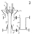
- a transmission mechanism is organized for the motorization of accessories 1,2 of a rotorcraft, such as an alternator 1 and a compressor 2. It will be noted at this stage of the description that these accessories 1,2, and their situation in the mechanism, are cited and illustrated by way of nonlimiting example as to the scope of the present invention.
- These accessories 1, 2 are motorized from one of the 3 driving members of a pair of rotorcraft drive members 3,4 for driving the rotor 5.
- This transmission mechanism comprises a driving shaft 6 in relation to with the motor unit 3 assigned to the motorization of accessories 1.2.
- This driving shaft 6 is in relation with a main shaft 7 driving the rotor 5, via a main member 8 with differential rotation speeds. and via a selectively driving member 9 of the main shaft 7 by the driving shaft 6.
- the main shaft 7 is in relation with the rotor 5 via a gear, including in particular a drive member 10 of the rotor 5 which it is provided, such as a bevel gear or the like.
- the main shaft 7 is more particularly mounted coaxially around the drive shaft 6, the main member 8 with a differential speed of rotation consisting of a main freewheel interposed between them.
- the selectively driving member 9 is interposed between the drive shaft 6 and the free wheel 8, being operable axially by a member 11 arranged in axial rod or the like.
- This selectively driving member 9 is in particular constituted in the usual manner in the field by a dog clutch device operable by the axial rod 11, whose known details are not shown.
- the driving shaft 6 is also related to a secondary shaft 12 for driving the accessories 1 and 2.
- the secondary shaft 12 is more particularly coaxial with the driving shaft 6 that it extends, extending at least partially inside the main shaft 7.
- this secondary shaft 12 advantageously houses the rod axial 11 maneuvering the selective drive member 9, which emerges at its end opposite to that of the extension of the drive shaft 6.
- the secondary shaft 12 and the axial rod 11 for operating the selectively driving member 8 coincide. More specifically, the axial rod 11 constitutes in itself the secondary shaft 12, being in relation with the intermediate shaft (13) via the secondary member (16,17) differential speed of rotation.
- the bead wire 11 has at its distal end, opposite to that used for its operation, a control member 25 for the operation of the selectively-driving member 9, which co-operates in particular with the freewheel 8.
- the selectively-driving member 9 and the freewheel 8 are arranged in a rotary-cage freewheel known per se in the field.
- the accessories 1 and 2 are connected to the main shaft 7 via a gear comprising an intermediate shaft 13.
- the latter 13 is in direct engagement with the main shaft 7, via a set of gears 14 and 15 or the like which are assigned to them.
- This set of gears comprises in particular a first pinion 14, which is provided with the intermediate shaft 13, which is engaged on a drive input pinion 15 fitted to the main shaft 7.
- the intermediate shaft 13 is also in relation with the secondary shaft 12 via a secondary member 16,17 differential rotation speeds and an output gear 23 motorization for driving accessories 1 and 2.
- This secondary member with differential rotation speeds is composed of a set of secondary free wheels 16,17 or the like.
- a first secondary freewheel 16 is interposed between the intermediate shaft 13 and a second pinion 18 equipping the latter 13, while a second secondary freewheel 17 is interposed between the second pinion 18 and the secondary shaft 12.
- the intermediate gear between the accessories 1 and 2 and the secondary shaft 12 further comprises a first elementary drive shaft 19 accessories 1 and 2, which is engaged on the secondary shaft 12.
- a second elementary shaft 20 d The drive of the accessories 1 and 2 is engaged on the intermediate shaft 13.
- these accessory sockets respectively on the secondary shaft and on the intermediate shaft are, if appropriate, made through the intermediate shaft.
- an elementary gear 21,24 and 22 respectively as illustrated.
- Such an arrangement of the transmission mechanism of the present invention allows in general its motorization accessories 1 and 2 not only with the motor member 3 which is directly affected, but also in case of failure of the latter 3 with the other motor unit 4 driving the rotor 5, or even the rotor 5 itself when it is autorotating in the event of breakdowns of the engines 3 and 4 of the rotorcraft.
- the transition from one to the other of these training situations accessories 1 and 2 is allowed without having to interrupt the training of the latter, even momentarily.
- This option is offered with additional weight and reduced space, and without inducing a change in the usual operating conditions of such a mechanism, particularly with regard to the procedures for connecting the main shaft 7 and the motor shaft 6, and those of connection of the motor shaft 6 with the secondary drive shaft 12.
- the intermediate shaft 13 is immobilized in rotation due to its grip on the main shaft 7 by means of the conical gear 10.
- the main shaft 7 is itself immobile in the absence of rotor drive.
- Such immobilization of the intermediate shaft 13 does not, however, prevent the drive of the secondary shaft 12 by the drive shaft 6.
- the free wheel 17 is mounted on the secondary shaft 12 so that it drives the elementary gear 23.
- the free wheel 16 is mounted on the intermediate shaft 13 slidably, to allow the rotation of the second pinion 18, engaged on the elementary gear 23, while the intermediate shaft 13 is immobilized, in the absence of driving the rotor 5.
- the relative speeds between the main shaft 7 and the drive shaft 6 allowing the axial operation of the selectively driven member 8 by means of the rod 11, the intermediate shaft 13 and the secondary shaft 12 are respectively driven by the main shaft 7 and the drive shaft 6.
- the secondary shaft 12 is driven by the drive shaft 6, while the intermediate shaft 13 is driven by the rotor 5 by the intermediate of the main shaft 7 and gears 14 and 15, respectively first and motor input.
- the operation of the selective drive member 9 is performed at low speed differential, to avoid any risk of rupture of the bodies in the presence.
- the operation of the selective drive member 9 can be performed directly, in particular by the operation of the rod 11.
- the member 3 motor accessories 1 and 2 is in operation, its operating speed is gradually decreased. It follows that the low speed differential between the drive shaft 6 and the main shaft 7 allows the operation of the selective drive member 9 without risk of damage.
- the drive output gear 23 is nevertheless driven by the intermediate shaft 13, engaged on the main shaft 7 itself driven in rotation by the rotor 5.
- This drive is more particularly obtained by the successive connection between the main shaft 7 and the drive input gear 15 which it is equipped, with the first elementary gear 14 and thus the intermediate shaft 13 which supports it, then with the second pinion 18 and the output gear 23 motorization through the secondary member 16 and 17 differential rotation, in particular constituted by a free wheel set with ossicles or the like for example.
- the transmission device of the present invention is connected to a single pinion 10 driving the rotor 5, notwithstanding the presence of several drive members 3 and 4 used for the motorization of the latter. It follows that the transmission device of the present invention is likely to be installed on one side of the device, with the advantages provided relating in particular to its size and simplicity of structure.
Landscapes
- Engineering & Computer Science (AREA)
- Mechanical Engineering (AREA)
- General Engineering & Computer Science (AREA)
- Aviation & Aerospace Engineering (AREA)
- Auxiliary Drives, Propulsion Controls, And Safety Devices (AREA)
- Transmission Devices (AREA)
- Retarders (AREA)
- Connection Of Motors, Electrical Generators, Mechanical Devices, And The Like (AREA)
- Structure Of Transmissions (AREA)
- One-Way And Automatic Clutches, And Combinations Of Different Clutches (AREA)
Claims (10)
- Übertragungsmechanismus zwischen mindestens einem Zubehörteil (1, 2) und Antriebsorganen (3, 4) für den Antrieb eines Rotors (5) eines Drehflüglers, wobei ein erstes Antriebsorgan (3) dem Antrieb des Zubehörteils (1, 2) einzeln oder zusammen mit dem Rotor (5) zugeteilt ist, und ein zweites Antriebsorgan (4) nur für den Antrieb des Rotors (5) vorgesehen ist, wobei dieser Mechanismus eine Hauptwelle (7) aufweist, die mit einem Antriebsorgan (10) des Rotors (5) versehen ist, wobei die Hauptwelle mit einer Antriebswelle (6) in Eingriff auf dem ersten Antriebsorgan (3) über ein Hauptorgan (8) mit Drehgeschwindigkeitsdifferenzial und über ein Organ (9) zum selektiven Drehantrieb in Verbindung steht, wobei das Organ (9) zum selektiven Drehantrieb zwischen einer Stellung des kombinierten Antriebs des Zubehörteils (1, 2) und des Rotors (5), in der die Hauptwelle (7) in Eingriff auf der Antriebswelle (6) ist, und einer Stellung des einzelnen Antriebs nur zum Antreiben des Zubehörteils (1, 2) betätigbar ist, in der die Hauptwelle (7) nicht in Eingriff auf der Antriebswelle (6) ist, wobei das Zubehörteil (1, 2) über ein Zahnradgetriebe auf einer Sekundärwelle (12) in Verbindung mit der Antriebswelle (6) des ersten Antriebsorgans (3) in Eingriff ist, wobei das Zahnradgetriebe mindestens eine Zwischenwelle (13) aufweist, die zwischen die Hauptwelle (7) und die Sekundärwelle (12) eingefügt ist, wobei die Zwischenwelle (13) in direktem Eingriff auf der Hauptwelle (7) ist und auf der Sekundärwelle (12) in Eingriff ist, wobei ein Sekundärorgan (16,17) mit Drehgeschwindigkeitsdifferenzial zwischen die Sekundärwelle (12) und die Zwischenwelle (13) eingefügt ist, um den Antrieb der Zubehörteile (1, 2) entweder alleine über die Sekundärwelle (12, die von der Antriebswelle (6) in der Stellung des einzelnen Antriebs angetrieben wird, oder über die Zwischenwelle (13) zu erlauben, die von der Hauptwelle (7) angetrieben wird, und wobei die Hauptwelle (7) koaxial zur Antriebswelle (6) montiert ist, wobei das Organ (9) für den selektiven Antrieb zwischen die Antriebswelle (6) und das Hauptorgan (8) mit Drehgeschwindigkeitsdifferenzial eingefügt ist, wobei der Mechanismus eine axiale Stange (11) zur Betätigung des selektiven Antriebsorgans (9) aufweist.
- Mechanismus nach Anspruch 1, bei dem die Zwischenwelle (13) mit einem ersten Zahnrad (14) in Eingriff auf einem Eingangs-Antriebszahnrad (15), das die Hauptwelle (7) bestückt, und mit einem zweiten Zahnrad (18) bestückt ist, das einerseits mit der Sekundärwelle (12) über das Sekundärorgan (16, 17) mit Geschwindigkeitsdifferenzial verbunden und andererseits auf einem Ausgangs-Antriebszahnrad (23) für den Antrieb der Zubehörteile (1, 2) in Eingriff ist.
- Mechanismus nach Anspruch 2, bei dem das Sekundärorgan (16, 17) mit Geschwindigkeitsdifferenzial ein Paar von sekundären Freilaufrädern aufweist, die zwischen das zweite Zahnrad (18) und die Zwischenwelle (13) für ein erstes sekundäres Freilaufrad (16), und zwischen das Antriebs-Ausgangszahnrad (23) und die Sekundärwelle (12) für ein zweites sekundäres Freilaufrad (17) eingefügt sind.
- Mechanismus nach einem der Ansprüche 2 oder 3, bei dem die Verhältnisse zwischen dem Eingangs-Antriebszahnrad (15) und dem ersten Zahnrad (14) einerseits und zwischen dem Ausgangs-Antriebszahnrad (23) und dem zweiten Zahnrad (18) andererseits die folgende Ungleichheit erfüllen
 - Z 15 die Anzahl von Zähnen des Eingangs-Antriebszahnrads ist,- Z14 die Anzahl von Zähnen des ersten Zahnrads ist,- Z23 die Anzahl von Zähnen des Ausgangs-Antriebszahnrads ist,- Z 18 die Anzahl von Zähnen des zweiten Zahnrads ist.
 - Mechanismus nach einem der vorhergehenden Ansprüche, bei dem die Hauptwelle (7) koaxial um die Antriebswelle (6) montiert ist, wobei das Hauptorgan (8) mit Drehgeschwindigkeitsdifferenzial hauptsächlich aus einem Haupt-Freilaufrad besteht, das zwischen ihnen angeordnet ist.
- Mechanismus nach einem der Ansprüche 1 bis 5, bei dem die Sekundärwelle (12) koaxial zur Antriebswelle (6) ist, die sie verlängert, wobei die Antriebswelle (6) sich zumindest teilweise innerhalb der Hauptwelle (7) erstreckt und die Stange (11) aufnimmt, die an ihrem dem Verlängerungsende der Antriebswelle (6) gegenüberliegenden Ende austritt.
- Mechanismus nach einem der Ansprüche 1 bis 5, bei dem die Sekundärwelle (12) und die Stange (11) zur Betätigung des Organs (9) zum selektiven Antrieb zusammenfallen, wobei die Stange (11) mit der Zwischenwelle (13) über das Sekundärorgan (16, 17) mit Drehgeschwindigkeitsdifferenzial in Verbindung steht und an ihrem fernen Ende gegenüber demjenigen, das für ihre Betätigung verwendet wird, ein Steuerorgan (25) zur Betätigung des Organs (9) zum selektiven Antrieb aufweist.
- Mechanismus nach einem der vorhergehenden Ansprüche, bei dem eine erste elementare Antriebswelle (19) der Zubehörteile (1, 2) auf der Sekundärwelle (12) in Eingriff ist, während eine zweite elementare Antriebswelle (20) der Zubehörteile (1, 2) auf der Zwischenwelle (13) in Eingriff ist.
- Mechanismus nach Anspruch 4, bei dem der Übergang zwischen der Stellung der einzelnen Antriebs und der Stellung des kombinierten Antriebs mit einem Drehgeschwindigkeitsdifferenzial zwischen den Geschwindigkeiten der Antriebswelle (6) und der Hauptwelle (7) erfolgt.
- Mechanismus nach Anspruch 4, bei dem der Übergang zwischen der Stellung des einzelnen Antriebs und der Stellung des kombinierten Antriebs ausgehend von einer Verringerung der Betriebsdrehzahl des ersten Antriebsorgans (3) im Vergleich mit der Betriebsdrehzahl des zweiten Antriebsorgans (4) erfolgt, um die Betätigung des Organs (9) zum selektiven Antrieb zu vereinfachen.
Applications Claiming Priority (2)
| Application Number | Priority Date | Filing Date | Title |
|---|---|---|---|
| FR0406131A FR2871138B1 (fr) | 2004-06-07 | 2004-06-07 | Mecanisme de transmission entre des accessoires et les organes moteurs d'entrainement du rotor d'un giravion, selectivement isolement ou conjointement |
| PCT/FR2005/001319 WO2006005830A1 (fr) | 2004-06-07 | 2005-06-01 | Mecanisme de transmission entre des accessoires et les organes moteurs d'entrainement du rotor d'un giravion, selectivement isolement ou conjointement. |
Publications (2)
| Publication Number | Publication Date |
|---|---|
| EP1753657A1 EP1753657A1 (de) | 2007-02-21 |
| EP1753657B1 true EP1753657B1 (de) | 2008-08-13 |
Family
ID=34945623
Family Applications (1)
| Application Number | Title | Priority Date | Filing Date |
|---|---|---|---|
| EP05773025A Ceased EP1753657B1 (de) | 2004-06-07 | 2005-06-01 | Übertragungsmechanismus zwischen zubehörelementen und anlasselementen, selektive, individuelle oder gemeinsame steuerung eines drehflügelrotors |
Country Status (8)
| Country | Link |
|---|---|
| US (1) | US7418888B2 (de) |
| EP (1) | EP1753657B1 (de) |
| JP (1) | JP4414462B2 (de) |
| KR (1) | KR100843307B1 (de) |
| CN (1) | CN100482537C (de) |
| DE (1) | DE602005008952D1 (de) |
| FR (1) | FR2871138B1 (de) |
| WO (1) | WO2006005830A1 (de) |
Cited By (1)
| Publication number | Priority date | Publication date | Assignee | Title |
|---|---|---|---|---|
| CN104061284A (zh) * | 2014-06-23 | 2014-09-24 | 深圳市高士通科技有限公司 | 无人直升机用t型二级减速器 |
Families Citing this family (21)
| Publication number | Priority date | Publication date | Assignee | Title |
|---|---|---|---|---|
| US20050025825A1 (en) * | 2003-07-31 | 2005-02-03 | Xanodyne Pharmacal, Inc. | Tranexamic acid formulations with reduced adverse effects |
| US8022106B2 (en) | 2004-03-04 | 2011-09-20 | Ferring B.V. | Tranexamic acid formulations |
| US20050244495A1 (en) | 2004-03-04 | 2005-11-03 | Xanodyne Pharmaceuticals, Inc. | Tranexamic acid formulations |
| US20050245614A1 (en) * | 2004-03-04 | 2005-11-03 | Xanodyne Pharmaceuticals, Inc. | Tranexamic acid formulations |
| ES2702125T3 (es) * | 2005-06-23 | 2019-02-27 | Ital Res & Innovation S R L | Máquina combinada multiuso |
| AU2006318319B2 (en) * | 2005-11-18 | 2013-01-17 | Glaxo Group Limited | Machine and method for pharmaceutical and pharmaceutical-like product assembly |
| US7536927B2 (en) * | 2006-06-05 | 2009-05-26 | Brose Fahrzeugteile GmbH & Co. Kommanditgesellschaft, Würzburg | Window lift drive for raising and lowering windows in a vehicle door |
| FR2928192B1 (fr) * | 2008-02-28 | 2010-03-19 | Eurocopter France | Boite de transmission de puissance presentant en sortie une vitesse de rotation modifiable et procede de fonctionnement correspondant |
| WO2009111724A1 (en) * | 2008-03-06 | 2009-09-11 | Karem Aircraft, Inc. | Torque balancing gearbox |
| US8133155B2 (en) * | 2009-07-14 | 2012-03-13 | Bell Helicopter Textron Inc. | Multi-ratio rotorcraft drive system and a method of changing gear ratios thereof |
| EP2653751A1 (de) * | 2012-04-17 | 2013-10-23 | Siemens Aktiengesellschaft | Getriebemotorenbaureihe |
| FR2992630B1 (fr) * | 2012-06-29 | 2015-02-20 | Turbomeca | Procede et configuration d'apport d'energie propulsive et/ou non propulsive dans une architecture d'helicoptere par un moteur auxiliaire de puissance |
| EP2818419B1 (de) * | 2013-06-27 | 2017-04-12 | Airbus Defence and Space Limited | Drehbare Anordnung |
| ITVR20130272A1 (it) * | 2013-12-09 | 2015-06-10 | Siral S R L | Dispositivo di cambio di velocità per mezzi di trasporto |
| FR3019247B1 (fr) * | 2014-03-27 | 2017-09-01 | Turbomeca | Ensemble de transmission pour aeronef et helicoptere |
| CN104864073A (zh) * | 2015-05-08 | 2015-08-26 | 博艳萍 | 一种双向安装式齿轮驱动机构 |
| CN104960664A (zh) * | 2015-05-26 | 2015-10-07 | 北京理工大学 | 一种重型可跳飞式自转旋翼飞行器复合跳飞系统 |
| FR3055934B1 (fr) * | 2016-09-09 | 2018-08-17 | Airbus Helicopters | Systeme mecanique de transmission d'un mouvement et aeronef equipe d'un systeme correspondant |
| FR3055883B1 (fr) * | 2016-09-09 | 2019-03-29 | Airbus Helicopters | Systeme mecanique de transmission d'un mouvement et aeronef equipe d'un systeme correspondant |
| FR3072944B1 (fr) * | 2017-10-26 | 2019-10-11 | Airbus Helicopters | Procede et dispositif d'optimisation de puissance dans une installation motrice |
| FR3147793A1 (fr) | 2023-04-13 | 2024-10-18 | Airbus Helicopters | procédé de pilotage d’un aéronef à voilure tournante multimoteur à consommation de carburant réduite au sol |
Family Cites Families (16)
| Publication number | Priority date | Publication date | Assignee | Title |
|---|---|---|---|---|
| US2979968A (en) * | 1958-08-28 | 1961-04-18 | United Aircraft Corp | Power transmission system |
| FR1325704A (fr) * | 1962-03-14 | 1963-05-03 | Sud Aviation | Perfectionnement apporté aux boîtes de transmission pour hélicoptères monorotor à plusieurs turbines |
| GB1389403A (en) * | 1971-06-01 | 1975-04-03 | Westland Aircraft Ltd | Helicopter power transmission systems |
| IT1179663B (it) | 1984-05-14 | 1987-09-16 | Agusta Aeronaut Costr | Trasmissione principale per elicotteri |
| FR2568541B1 (fr) * | 1984-08-06 | 1987-03-20 | Aerospatiale | Boite de transmission principale pour helicoptere bimoteur |
| GB8625712D0 (en) * | 1986-10-28 | 1987-03-18 | Westland Plc | Transmission system |
| US5108043A (en) * | 1991-03-29 | 1992-04-28 | Bell Helicopter Textron, Inc. | Twin engine helicopter accesssory drive |
| CN1025951C (zh) * | 1992-05-30 | 1994-09-21 | 李晓阳 | 一种共轴旋翼飞行器的传动差速机构 |
| US5281099A (en) * | 1992-06-22 | 1994-01-25 | United Technologies Corporation | Integrated spline/cone seat subassembly for a rotor assembly having ducted, coaxial counter-rotating rotors |
| IT1261872B (it) * | 1993-09-17 | 1996-06-03 | Fiatavio Spa | Applicazione di ingranaggi facciali a trasmissioni per elicotteri. |
| US5472386A (en) * | 1994-05-26 | 1995-12-05 | United Technologies Corporation | Stacked compound planetary gear train for an upgraded powertrain system for a helicopter |
| JP3029976B2 (ja) * | 1995-01-27 | 2000-04-10 | 株式会社コミュータヘリコプタ先進技術研究所 | ヘリコプタの動力伝達装置 |
| JP3029981B2 (ja) * | 1995-04-27 | 2000-04-10 | 株式会社コミュータヘリコプタ先進技術研究所 | ヘリコプタの動力伝達装置 |
| US5802918A (en) * | 1996-10-16 | 1998-09-08 | Mcdonnell Douglas Helicopter Co. | Concentric face gear transmission assembly |
| US5853145A (en) * | 1997-01-09 | 1998-12-29 | Cartercopters, Llc | Rotor head for rotary wing aircraft |
| US6443035B1 (en) * | 2001-09-20 | 2002-09-03 | The Boeing Company | Hybrid power input quill for transmissions |
-
2004
- 2004-06-07 FR FR0406131A patent/FR2871138B1/fr not_active Expired - Fee Related
-
2005
- 2005-06-01 EP EP05773025A patent/EP1753657B1/de not_active Ceased
- 2005-06-01 JP JP2007514021A patent/JP4414462B2/ja not_active Expired - Fee Related
- 2005-06-01 WO PCT/FR2005/001319 patent/WO2006005830A1/fr not_active Ceased
- 2005-06-01 KR KR1020067024935A patent/KR100843307B1/ko not_active Expired - Lifetime
- 2005-06-01 CN CNB200580018110XA patent/CN100482537C/zh not_active Expired - Fee Related
- 2005-06-01 DE DE602005008952T patent/DE602005008952D1/de not_active Expired - Lifetime
- 2005-06-07 US US11/145,928 patent/US7418888B2/en active Active
Cited By (2)
| Publication number | Priority date | Publication date | Assignee | Title |
|---|---|---|---|---|
| CN104061284A (zh) * | 2014-06-23 | 2014-09-24 | 深圳市高士通科技有限公司 | 无人直升机用t型二级减速器 |
| CN104061284B (zh) * | 2014-06-23 | 2016-10-26 | 深圳市高士通科技有限公司 | 无人直升机用t型二级减速器 |
Also Published As
| Publication number | Publication date |
|---|---|
| US20060000300A1 (en) | 2006-01-05 |
| CN1964888A (zh) | 2007-05-16 |
| US7418888B2 (en) | 2008-09-02 |
| EP1753657A1 (de) | 2007-02-21 |
| KR100843307B1 (ko) | 2008-07-04 |
| FR2871138A1 (fr) | 2005-12-09 |
| JP2008501564A (ja) | 2008-01-24 |
| JP4414462B2 (ja) | 2010-02-10 |
| KR20070020050A (ko) | 2007-02-16 |
| CN100482537C (zh) | 2009-04-29 |
| DE602005008952D1 (de) | 2008-09-25 |
| WO2006005830A1 (fr) | 2006-01-19 |
| FR2871138B1 (fr) | 2006-08-04 |
Similar Documents
| Publication | Publication Date | Title |
|---|---|---|
| EP1753657B1 (de) | Übertragungsmechanismus zwischen zubehörelementen und anlasselementen, selektive, individuelle oder gemeinsame steuerung eines drehflügelrotors | |
| EP2512855B1 (de) | Motorisierte nabe mit kupplungs- und entkupplungsmitteln | |
| EP3034397B1 (de) | Motorisierungssystem eines rads, das mit einer aufhängung versehen ist | |
| EP2431274B1 (de) | Drehflügelflugzeug mit einem Antriebsmittel und von diesem Flugzeug angewendeten Verfahren. | |
| EP1845016B1 (de) | Fahrwerk umfassend mehrere elektromechanische Ausrichtungsstellglieder | |
| EP0224407B1 (de) | Zahnradgetriebe mit einer Antriebswelle und zwei Vorgelegewellen | |
| EP1541834A1 (de) | Hilfsgeräteantrieb für ein Zweiwellenflugtriebwerk | |
| WO2015052430A1 (fr) | Boitier d'entrainement d'accessoires pour turbomachine | |
| FR2973334A1 (fr) | Actionneur rotatif a haute integrite et procede de commande | |
| FR2954236A1 (fr) | Systeme de motorisation electrique d'une roue | |
| EP0227503A1 (de) | Ausbaufähiges Getriebe mit parallelen Achsen und Planetensatz, insbesondere für Motorfahrzeuge | |
| FR2939763A1 (fr) | Train d'atterrissage motorise pour aeronef | |
| EP2174868A1 (de) | Vorrichtung zum Antrieb des ersten und zweiten Hauptrotors eines Tragschraubers mit zwei in Tandem angeordneten Hauptrotoren | |
| EP3176469B1 (de) | Lenksystem mit mechanischem differenzial geringen platzbedarfs | |
| WO2014013084A1 (fr) | Moyeu motorise comprenant un changement de rapport et des moyens de couplage et de decouplage | |
| WO2023209291A1 (fr) | Boîtier de relais d'accessoires et turbomachine d'aéronef comportant un tel boîtier | |
| EP3293111B1 (de) | Mechanisches system zur übertragung einer bewegung, und mit einem solchen system ausgestattetes luftfahrzeug | |
| FR2966786A3 (fr) | Systeme de motorisation hybride pour vehicule automobile | |
| FR3013262A1 (fr) | Groupe moteur destine a equiper un aeronef convertible | |
| EP0819864B1 (de) | Kompakte Synchronisiereinrichtung für ein Zahnradwechselgetriebe, insbesondere für ein Kraftfahrzeug | |
| FR3008955A1 (fr) | Dispositif d'entrainement en rotation d'une roue d'aeronef | |
| EP1097317A1 (de) | Wendegetriebe montiert zwischen einem wechselgetriebe und mindestens zwei angetriebenen rädern | |
| FR2683013A1 (fr) | Dispositif de transmission modulaire et groupe moto-propulseur ainsi equipe. | |
| FR2929562A1 (fr) | Vehicule leger muni d'un ensemble propulsif sans differentiel. | |
| US20100173741A1 (en) | Method of altering a drive ratio on a driven wheel and a drive assembly in accordance with the method |
Legal Events
| Date | Code | Title | Description |
|---|---|---|---|
| PUAI | Public reference made under article 153(3) epc to a published international application that has entered the european phase |
Free format text: ORIGINAL CODE: 0009012 |
|
| 17P | Request for examination filed |
Effective date: 20061025 |
|
| AK | Designated contracting states |
Kind code of ref document: A1 Designated state(s): DE GB IT |
|
| TPAC | Observations filed by third parties |
Free format text: ORIGINAL CODE: EPIDOSNTIPA |
|
| DAX | Request for extension of the european patent (deleted) | ||
| RBV | Designated contracting states (corrected) |
Designated state(s): DE GB IT |
|
| GRAP | Despatch of communication of intention to grant a patent |
Free format text: ORIGINAL CODE: EPIDOSNIGR1 |
|
| GRAS | Grant fee paid |
Free format text: ORIGINAL CODE: EPIDOSNIGR3 |
|
| GRAA | (expected) grant |
Free format text: ORIGINAL CODE: 0009210 |
|
| AK | Designated contracting states |
Kind code of ref document: B1 Designated state(s): DE GB IT |
|
| REG | Reference to a national code |
Ref country code: GB Ref legal event code: FG4D Free format text: NOT ENGLISH |
|
| REF | Corresponds to: |
Ref document number: 602005008952 Country of ref document: DE Date of ref document: 20080925 Kind code of ref document: P |
|
| PLBE | No opposition filed within time limit |
Free format text: ORIGINAL CODE: 0009261 |
|
| STAA | Information on the status of an ep patent application or granted ep patent |
Free format text: STATUS: NO OPPOSITION FILED WITHIN TIME LIMIT |
|
| 26N | No opposition filed |
Effective date: 20090514 |
|
| REG | Reference to a national code |
Ref country code: DE Ref legal event code: R082 Ref document number: 602005008952 Country of ref document: DE Representative=s name: GPI & ASSOCIES, FR |
|
| REG | Reference to a national code |
Ref country code: DE Ref legal event code: R082 Ref document number: 602005008952 Country of ref document: DE Representative=s name: GPI & ASSOCIES, FR Ref country code: DE Ref legal event code: R081 Ref document number: 602005008952 Country of ref document: DE Owner name: AIRBUS HELICOPTERS, FR Free format text: FORMER OWNER: EUROCOPTER, MARIGNANE, FR |
|
| PGFP | Annual fee paid to national office [announced via postgrant information from national office to epo] |
Ref country code: GB Payment date: 20200625 Year of fee payment: 16 |
|
| PGFP | Annual fee paid to national office [announced via postgrant information from national office to epo] |
Ref country code: DE Payment date: 20210618 Year of fee payment: 17 |
|
| GBPC | Gb: european patent ceased through non-payment of renewal fee |
Effective date: 20210601 |
|
| PG25 | Lapsed in a contracting state [announced via postgrant information from national office to epo] |
Ref country code: GB Free format text: LAPSE BECAUSE OF NON-PAYMENT OF DUE FEES Effective date: 20210601 |
|
| PGFP | Annual fee paid to national office [announced via postgrant information from national office to epo] |
Ref country code: IT Payment date: 20220627 Year of fee payment: 18 |
|
| REG | Reference to a national code |
Ref country code: DE Ref legal event code: R119 Ref document number: 602005008952 Country of ref document: DE |
|
| PG25 | Lapsed in a contracting state [announced via postgrant information from national office to epo] |
Ref country code: DE Free format text: LAPSE BECAUSE OF NON-PAYMENT OF DUE FEES Effective date: 20230103 |
|
| PG25 | Lapsed in a contracting state [announced via postgrant information from national office to epo] |
Ref country code: IT Free format text: LAPSE BECAUSE OF NON-PAYMENT OF DUE FEES Effective date: 20230601 |