EP1753657B1 - Transmission mechanism between accessories and motoring members, driving a rotorcraft rotor, selectively, individually or jointly - Google Patents
Transmission mechanism between accessories and motoring members, driving a rotorcraft rotor, selectively, individually or jointly Download PDFInfo
- Publication number
- EP1753657B1 EP1753657B1 EP05773025A EP05773025A EP1753657B1 EP 1753657 B1 EP1753657 B1 EP 1753657B1 EP 05773025 A EP05773025 A EP 05773025A EP 05773025 A EP05773025 A EP 05773025A EP 1753657 B1 EP1753657 B1 EP 1753657B1
- Authority
- EP
- European Patent Office
- Prior art keywords
- shaft
- drive
- gear
- accessories
- rotor
- Prior art date
- Legal status (The legal status is an assumption and is not a legal conclusion. Google has not performed a legal analysis and makes no representation as to the accuracy of the status listed.)
- Ceased
Links
- 230000007246 mechanism Effects 0.000 title claims description 33
- 230000005540 biological transmission Effects 0.000 title claims description 20
- 238000002955 isolation Methods 0.000 claims description 2
- 210000000056 organ Anatomy 0.000 description 6
- 230000007704 transition Effects 0.000 description 4
- 238000002360 preparation method Methods 0.000 description 3
- 230000015556 catabolic process Effects 0.000 description 2
- 230000008859 change Effects 0.000 description 2
- 238000012423 maintenance Methods 0.000 description 2
- 230000008520 organization Effects 0.000 description 2
- 101100536354 Drosophila melanogaster tant gene Proteins 0.000 description 1
- 239000011324 bead Substances 0.000 description 1
- 230000003247 decreasing effect Effects 0.000 description 1
- 230000001627 detrimental effect Effects 0.000 description 1
- 230000009977 dual effect Effects 0.000 description 1
- 235000021183 entrée Nutrition 0.000 description 1
- 230000001939 inductive effect Effects 0.000 description 1
- 230000009347 mechanical transmission Effects 0.000 description 1
- 238000000034 method Methods 0.000 description 1
- 230000000717 retained effect Effects 0.000 description 1
- 238000004513 sizing Methods 0.000 description 1
Images

Classifications
-
- F—MECHANICAL ENGINEERING; LIGHTING; HEATING; WEAPONS; BLASTING
- F16—ENGINEERING ELEMENTS AND UNITS; GENERAL MEASURES FOR PRODUCING AND MAINTAINING EFFECTIVE FUNCTIONING OF MACHINES OR INSTALLATIONS; THERMAL INSULATION IN GENERAL
- F16H—GEARING
- F16H1/00—Toothed gearings for conveying rotary motion
- F16H1/02—Toothed gearings for conveying rotary motion without gears having orbital motion
- F16H1/20—Toothed gearings for conveying rotary motion without gears having orbital motion involving more than two intermeshing members
- F16H1/22—Toothed gearings for conveying rotary motion without gears having orbital motion involving more than two intermeshing members with a plurality of driving or driven shafts; with arrangements for dividing torque between two or more intermediate shafts
-
- B—PERFORMING OPERATIONS; TRANSPORTING
- B64—AIRCRAFT; AVIATION; COSMONAUTICS
- B64C—AEROPLANES; HELICOPTERS
- B64C27/00—Rotorcraft; Rotors peculiar thereto
- B64C27/04—Helicopters
- B64C27/12—Rotor drives
- B64C27/14—Direct drive between power plant and rotor hub
-
- Y—GENERAL TAGGING OF NEW TECHNOLOGICAL DEVELOPMENTS; GENERAL TAGGING OF CROSS-SECTIONAL TECHNOLOGIES SPANNING OVER SEVERAL SECTIONS OF THE IPC; TECHNICAL SUBJECTS COVERED BY FORMER USPC CROSS-REFERENCE ART COLLECTIONS [XRACs] AND DIGESTS
- Y10—TECHNICAL SUBJECTS COVERED BY FORMER USPC
- Y10T—TECHNICAL SUBJECTS COVERED BY FORMER US CLASSIFICATION
- Y10T74/00—Machine element or mechanism
- Y10T74/19—Gearing
- Y10T74/19023—Plural power paths to and/or from gearing
- Y10T74/19126—Plural drivers plural driven
- Y10T74/19135—Spur
-
- Y—GENERAL TAGGING OF NEW TECHNOLOGICAL DEVELOPMENTS; GENERAL TAGGING OF CROSS-SECTIONAL TECHNOLOGIES SPANNING OVER SEVERAL SECTIONS OF THE IPC; TECHNICAL SUBJECTS COVERED BY FORMER USPC CROSS-REFERENCE ART COLLECTIONS [XRACs] AND DIGESTS
- Y10—TECHNICAL SUBJECTS COVERED BY FORMER USPC
- Y10T—TECHNICAL SUBJECTS COVERED BY FORMER US CLASSIFICATION
- Y10T74/00—Machine element or mechanism
- Y10T74/19—Gearing
- Y10T74/19642—Directly cooperating gears
- Y10T74/19647—Parallel axes or shafts
Definitions
- the invention is in the field of mechanical transmission, and more particularly mechanisms for selectively relating a rotating shaft with one or alternatively several driving sources. It relates to such a transmission mechanism for driving accessories, such as an alternator and / or a compressor, from drive members driving a shaft, and in particular a rotor drive shaft of a rotorcraft, selectively in isolation or together.
- driving accessories such as an alternator and / or a compressor
- a general problem lies in the dual destination of the rotorcraft engines, both for driving the rotor and, for one of them at least, for the motorization of accessories. This problem is made all the more difficult to solve as it is common to drive the accessories independently of the rotor while the rotorcraft is on the ground, in pre-flight or waiting phase in particular. For this purpose, it is usual to affect one of the drive members to drive the accessories while the connection between the rotor and all the drive members is broken.
- the motor unit assigned to the motorization of accessories is on the one hand in relation with a main shaft driving the rotor via a selective drive member, such as interconnection mechanism or the like, and secondly in connection with a secondary drive shaft accessories.
- a selective drive member such as interconnection mechanism or the like
- the drive member of the accessories may alternatively be driving the accessories only, or jointly drive them with the rotor.
- patents are known FR 2 140 107 and US 3,782,223 revealing a device that has a large number of parts and is complex, cumbersome and relatively fragile.
- the object of the present invention is to propose a solution relating to the maintenance of the motorization of the accessories of a rotorcraft, including between the phases of motorization of the accessories by the sole drive member assigned to them and / or jointly with the rotor .
- This solution must nevertheless make possible the usual selective operation of driving these accessories by the drive members, and more particularly selectively isolated by the drive member assigned to the accessories or jointly by all the drive members of the rotor drive.
- the mechanism of the present invention is a transmission mechanism between at least one accessory and the drive members of a general shaft drive rotor of a rotorcraft in particular.
- This transmission mechanism is of the kind organized to allow accessories to be driven selectively one of the driving members assigned to their motorization, or jointly by all of the drive members of the rotor, particularly in pairs. More specifically, said drive members are assigned for one to the motorization of the accessory alone or together with the rotor and for the other at least to the motor alone rotor.
- This mechanism comprises a main shaft which is provided with a rotor drive member, such as a bevel gear, and which is in relation with a motor shaft engaged on the motor member assigned to the motorization of the accessory. .
- This linking is carried out by means of a main member with differential rotation speeds, including freewheel or the like, and a selectively rotating drive member with axial operation, such as a jaw clutching device. in particular or the like.
- This selective drive is performed between a combined motor position of the accessory and the rotor, in which the main shaft is engaged on the motor shaft, and an isolated motor position in which this socket is broken, for the accessory training only.
- This accessory is engaged via a gear on a secondary shaft in relation to the drive shaft of the accessory drive member.
- the intermediate shaft is oriented parallel to the main shaft and the secondary shaft, without such a measure being restrictive as to the scope of the present invention.
- the main rotational speed differential member is advantageously constituted by a main freewheel interposed between the main shaft and indifferently any one of the secondary shaft and the motor shaft.
- the selectively rotating drive member in particular consisting of a clutch device, is meanwhile interposed between the main freewheel and the drive shaft and / or the secondary shaft, being axially operable by an emerging rod. advantageously at the end of the secondary shaft opposite to that through which it is abutted to the drive shaft.
- the intermediate shaft is equipped with a first pinion meshing with a motor input pinion. equipping the main shaft, and a second pinion on the one hand in relation to the secondary shaft via the differential secondary gear member, and secondly on an output pinion of motorization.
- the secondary differential gear member is in turn preferentially composed of a pair of secondary freewheels or the like, which are interposed between the second gear and the intermediate shaft for a first secondary freewheel, and between the output gear motor and the secondary shaft for a second secondary freewheel.
- a transmission mechanism is organized for the motorization of accessories 1,2 of a rotorcraft, such as an alternator 1 and a compressor 2. It will be noted at this stage of the description that these accessories 1,2, and their situation in the mechanism, are cited and illustrated by way of nonlimiting example as to the scope of the present invention.
- These accessories 1, 2 are motorized from one of the 3 driving members of a pair of rotorcraft drive members 3,4 for driving the rotor 5.
- This transmission mechanism comprises a driving shaft 6 in relation to with the motor unit 3 assigned to the motorization of accessories 1.2.
- This driving shaft 6 is in relation with a main shaft 7 driving the rotor 5, via a main member 8 with differential rotation speeds. and via a selectively driving member 9 of the main shaft 7 by the driving shaft 6.
- the main shaft 7 is in relation with the rotor 5 via a gear, including in particular a drive member 10 of the rotor 5 which it is provided, such as a bevel gear or the like.
- the main shaft 7 is more particularly mounted coaxially around the drive shaft 6, the main member 8 with a differential speed of rotation consisting of a main freewheel interposed between them.
- the selectively driving member 9 is interposed between the drive shaft 6 and the free wheel 8, being operable axially by a member 11 arranged in axial rod or the like.
- This selectively driving member 9 is in particular constituted in the usual manner in the field by a dog clutch device operable by the axial rod 11, whose known details are not shown.
- the driving shaft 6 is also related to a secondary shaft 12 for driving the accessories 1 and 2.
- the secondary shaft 12 is more particularly coaxial with the driving shaft 6 that it extends, extending at least partially inside the main shaft 7.
- this secondary shaft 12 advantageously houses the rod axial 11 maneuvering the selective drive member 9, which emerges at its end opposite to that of the extension of the drive shaft 6.
- the secondary shaft 12 and the axial rod 11 for operating the selectively driving member 8 coincide. More specifically, the axial rod 11 constitutes in itself the secondary shaft 12, being in relation with the intermediate shaft (13) via the secondary member (16,17) differential speed of rotation.
- the bead wire 11 has at its distal end, opposite to that used for its operation, a control member 25 for the operation of the selectively-driving member 9, which co-operates in particular with the freewheel 8.
- the selectively-driving member 9 and the freewheel 8 are arranged in a rotary-cage freewheel known per se in the field.
- the accessories 1 and 2 are connected to the main shaft 7 via a gear comprising an intermediate shaft 13.
- the latter 13 is in direct engagement with the main shaft 7, via a set of gears 14 and 15 or the like which are assigned to them.
- This set of gears comprises in particular a first pinion 14, which is provided with the intermediate shaft 13, which is engaged on a drive input pinion 15 fitted to the main shaft 7.
- the intermediate shaft 13 is also in relation with the secondary shaft 12 via a secondary member 16,17 differential rotation speeds and an output gear 23 motorization for driving accessories 1 and 2.
- This secondary member with differential rotation speeds is composed of a set of secondary free wheels 16,17 or the like.
- a first secondary freewheel 16 is interposed between the intermediate shaft 13 and a second pinion 18 equipping the latter 13, while a second secondary freewheel 17 is interposed between the second pinion 18 and the secondary shaft 12.
- the intermediate gear between the accessories 1 and 2 and the secondary shaft 12 further comprises a first elementary drive shaft 19 accessories 1 and 2, which is engaged on the secondary shaft 12.
- a second elementary shaft 20 d The drive of the accessories 1 and 2 is engaged on the intermediate shaft 13.
- these accessory sockets respectively on the secondary shaft and on the intermediate shaft are, if appropriate, made through the intermediate shaft.
- an elementary gear 21,24 and 22 respectively as illustrated.
- Such an arrangement of the transmission mechanism of the present invention allows in general its motorization accessories 1 and 2 not only with the motor member 3 which is directly affected, but also in case of failure of the latter 3 with the other motor unit 4 driving the rotor 5, or even the rotor 5 itself when it is autorotating in the event of breakdowns of the engines 3 and 4 of the rotorcraft.
- the transition from one to the other of these training situations accessories 1 and 2 is allowed without having to interrupt the training of the latter, even momentarily.
- This option is offered with additional weight and reduced space, and without inducing a change in the usual operating conditions of such a mechanism, particularly with regard to the procedures for connecting the main shaft 7 and the motor shaft 6, and those of connection of the motor shaft 6 with the secondary drive shaft 12.
- the intermediate shaft 13 is immobilized in rotation due to its grip on the main shaft 7 by means of the conical gear 10.
- the main shaft 7 is itself immobile in the absence of rotor drive.
- Such immobilization of the intermediate shaft 13 does not, however, prevent the drive of the secondary shaft 12 by the drive shaft 6.
- the free wheel 17 is mounted on the secondary shaft 12 so that it drives the elementary gear 23.
- the free wheel 16 is mounted on the intermediate shaft 13 slidably, to allow the rotation of the second pinion 18, engaged on the elementary gear 23, while the intermediate shaft 13 is immobilized, in the absence of driving the rotor 5.
- the relative speeds between the main shaft 7 and the drive shaft 6 allowing the axial operation of the selectively driven member 8 by means of the rod 11, the intermediate shaft 13 and the secondary shaft 12 are respectively driven by the main shaft 7 and the drive shaft 6.
- the secondary shaft 12 is driven by the drive shaft 6, while the intermediate shaft 13 is driven by the rotor 5 by the intermediate of the main shaft 7 and gears 14 and 15, respectively first and motor input.
- the operation of the selective drive member 9 is performed at low speed differential, to avoid any risk of rupture of the bodies in the presence.
- the operation of the selective drive member 9 can be performed directly, in particular by the operation of the rod 11.
- the member 3 motor accessories 1 and 2 is in operation, its operating speed is gradually decreased. It follows that the low speed differential between the drive shaft 6 and the main shaft 7 allows the operation of the selective drive member 9 without risk of damage.
- the drive output gear 23 is nevertheless driven by the intermediate shaft 13, engaged on the main shaft 7 itself driven in rotation by the rotor 5.
- This drive is more particularly obtained by the successive connection between the main shaft 7 and the drive input gear 15 which it is equipped, with the first elementary gear 14 and thus the intermediate shaft 13 which supports it, then with the second pinion 18 and the output gear 23 motorization through the secondary member 16 and 17 differential rotation, in particular constituted by a free wheel set with ossicles or the like for example.
- the transmission device of the present invention is connected to a single pinion 10 driving the rotor 5, notwithstanding the presence of several drive members 3 and 4 used for the motorization of the latter. It follows that the transmission device of the present invention is likely to be installed on one side of the device, with the advantages provided relating in particular to its size and simplicity of structure.
Landscapes
- Engineering & Computer Science (AREA)
- Mechanical Engineering (AREA)
- General Engineering & Computer Science (AREA)
- Aviation & Aerospace Engineering (AREA)
- Auxiliary Drives, Propulsion Controls, And Safety Devices (AREA)
- Transmission Devices (AREA)
- Retarders (AREA)
- Connection Of Motors, Electrical Generators, Mechanical Devices, And The Like (AREA)
- Structure Of Transmissions (AREA)
- One-Way And Automatic Clutches, And Combinations Of Different Clutches (AREA)
Description
L'invention est du domaine de la transmission mécanique, et plus particulièrement des mécanismes pour mettre sélectivement en relation un arbre tournant avec une ou alternativement plusieurs sources motrices. Elle a pour objet un tel mécanisme de transmission pour entraîner des accessoires, tel qu'un alternateur et/ou un compresseur, à partir des organes moteurs d'entraînement d'un arbre, et notamment un arbre d'entraînement du rotor d'un giravion, sélectivement isolément ou conjointement.The invention is in the field of mechanical transmission, and more particularly mechanisms for selectively relating a rotating shaft with one or alternatively several driving sources. It relates to such a transmission mechanism for driving accessories, such as an alternator and / or a compressor, from drive members driving a shaft, and in particular a rotor drive shaft of a rotorcraft, selectively in isolation or together.
On rappelle que dans le domaine des giravions, hélicoptères notamment ou analogues, il est commun d'entraîner le rotor au moyen de plusieurs organes moteurs, en couple notamment. On rappelle aussi que l'un au moins de ces organes moteurs est en outre mis à profit pour motoriser des accessoires du giravion, tels qu'un alternateur ou un compresseur par exemple. On notera à ce stade de la description que le nombre et la nature de ces accessoires ne sont pas limitatifs quant à la portée de la présente invention.It is recalled that in the field of rotorcraft, helicopters in particular or the like, it is common to drive the rotor by means of several driving members, in particular couple. It is also recalled that at least one of these drive members is also used to motorize accessories of the rotorcraft, such as an alternator or a compressor for example. It will be noted at this stage of the description that the number and nature of these accessories are not limiting as to the scope of the present invention.
Un problème général posé réside dans la double destination des organes moteurs du giravion, à la fois pour l'entraînement du rotor et, pour l'un d'eux au moins, pour la motorisation des accessoires. Ce problème est rendu d'autant plus délicat à résoudre qu'il est commun d'entraîner les accessoires indépendamment du rotor pendant que le giravion est au sol, en phase préparatoire au vol ou en phase d'attente notamment. A cet effet, il est habituel d'affecter l'un des organes moteurs à l'entraînement des accessoires alors que la liaison entre le rotor et l'ensemble des organes moteurs est rompue.A general problem lies in the dual destination of the rotorcraft engines, both for driving the rotor and, for one of them at least, for the motorization of accessories. This problem is made all the more difficult to solve as it is common to drive the accessories independently of the rotor while the rotorcraft is on the ground, in pre-flight or waiting phase in particular. For this purpose, it is usual to affect one of the drive members to drive the accessories while the connection between the rotor and all the drive members is broken.
Plus précisément, l'organe moteur affecté à la motorisation des accessoires est d'une part en relation avec un arbre principal d'entraînement du rotor par l'intermédiaire d'un organe d'entraînement sélectif, tel que mécanisme de crabotage ou analogue, et d'autre part en relation avec un arbre secondaire d'entraînement des accessoires. Ces dispositions sont telles qu'à partir de la manoeuvre de l'organe d'entraînement sélectif, l'organe de motorisation des accessoires puisse alternativement soit entraîner les accessoires seulement, soit entraîner conjointement ces derniers avec le rotor.More specifically, the motor unit assigned to the motorization of accessories is on the one hand in relation with a main shaft driving the rotor via a selective drive member, such as interconnection mechanism or the like, and secondly in connection with a secondary drive shaft accessories. These arrangements are such that from the operation of the selective drive member, the drive member of the accessories may alternatively be driving the accessories only, or jointly drive them with the rotor.
Notamment lors d'une phase de préparation du giravion, préalablement à une mise en rotation du rotor, la liaison entre l'organe de motorisation des accessoires et l'arbre principal est rompue, seuls les accessoires étant entraînés par cet organe moteur. Puis, cette phase de préparation étant achevée, la liaison entre l'organe de motorisation des accessoires et le rotor est établie par l'intermédiaire de l'organe d'entraînement sélectif. Notamment encore, lors d'une phase d'attente du giravion pendant laquelle un entraînement du rotor est momentanément interrompu, l'organe d'entraînement sélectif est manoeuvré pour rompre la liaison entre l'arbre principal et l'organe affecté à la motorisation des accessoires, l'entraînement de ces derniers perdurant néanmoins.In particular during a phase of preparation of the rotorcraft, prior to a rotation of the rotor, the connection between the drive member of the accessories and the main shaft is broken, only the accessories being driven by the drive member. Then, this preparation phase being completed, the connection between the drive member of the accessories and the rotor is established via the selective drive member. In particular, during a waiting phase of the rotorcraft during which a rotor drive is momentarily interrupted, the selective drive member is operated to break the link between the main shaft and the member assigned to the motorization of the rotorcraft. accessories, the training of these last ones nevertheless.
On connaît par exemple les brevets
On relèvera à ce stade de la description qu'il est en outre commun d'interposer entre les organes moteurs et les arbres principaux d'entraînement du rotor qui leur sont affectés, des mécanismes à différentiel de rotation, roues libres notamment ou analogues. Ces roues libres, rendues d'autant plus indispensables que le rotor présente une inertie conséquente, visent à rendre sans conséquence une différence de vitesse relative entre le rotor et l'un ou l'autre des arbres principaux d'entraînement de celui-ci en relation avec l'organe moteur correspondant. Cependant, il est courant de manoeuvrer axialement l'organe d'entraînement sélectif interposé entre l'arbre principal d'entraînement du rotor et l'organe de motorisation des accessoires, et une telle manoeuvre est rendue difficile, voire impossible, au delà d'un seuil admis de différence de vitesses de rotation entre le rotor et l'organe moteur affecté à la motorisation des accessoires.It will be noted at this stage of the description that it is also common to interpose between the drive members and the main rotor drive shafts assigned to them, differential rotation mechanisms, including freewheels or the like. These freewheels, made even more essential that the rotor has a substantial inertia, aim to make inconsequential a relative speed difference between the rotor and one or other of the main drive shafts thereof. relationship with the corresponding motor unit. However, it is common to axially manipulate the selective drive member interposed between the main drive shaft of the rotor and the drive member. motorization of the accessories, and such a maneuver is made difficult, if not impossible, beyond an admitted threshold difference in rotational speeds between the rotor and the motor unit assigned to the motorization of accessories.
Pour surmonter cette difficulté, il est commun lors du passage de la position d'entraînement des accessoires seuls à la position d'entraînement conjoint de ces derniers avec le rotor, d'attendre l'atteinte de ce seuil de différence de vitesses pour manoeuvrer l'organe d'entraînement sélectif et provoquer l'entraînement du rotor à partir de l'ensemble des organes moteurs. Inversement, lorsque le rotor est entraîné par l'ensemble des organes moteurs, la manoeuvre axiale de l'organe d'entraînement sélectif est provoquée, puis seul l'organe de motorisation des accessoires est maintenu en fonctionnement. La manoeuvre de l'organe d'entraînement sélectif étant rendue délicate en raison de la différence de rotation entre les différents organes moteurs, notamment entre la position d'entraînement des accessoires seuls et la position d'entraînement de ces derniers conjointement avec le rotor, il est communément admis d'avoir à interrompre momentanément l'entraînement des accessoires, jusqu'à l'obtention d'une harmonisation suffisante des vitesses d'entraînement des différents organes tournants les unes par rapport aux autres.To overcome this difficulty, it is common during the transition from the drive position of the accessories alone to the joint drive position of the latter with the rotor, to wait for the threshold of this difference in speed to maneuver. selective drive member and cause the rotor to be driven from all the driving members. Conversely, when the rotor is driven by all the drive members, the axial operation of the selective drive member is caused, then only the drive member of the accessories is kept in operation. The operation of the selective drive member being made difficult because of the difference in rotation between the various drive members, in particular between the drive position of the accessories alone and the driving position of the latter together with the rotor, it is commonly accepted to have to temporarily interrupt the drive accessories, until a sufficient harmonization of the drive speeds of different rotating members relative to each other.
Il est apparu à l'usage qu'une telle organisation générale du mécanisme de transmission n'est pas pleinement satisfaisante, notamment en raison du risque d'une perte de fonctionnement des accessoires lors de la phase d'attente de l'harmonisation susvisée des vitesses entre-elles, et/ou en cas de panne de l'un quelconque des moteurs. En effet, une rupture, même momentanée, de l'entraînement des accessoires, est préjudiciable lorsque parmi ceux-ci sont notamment compris un alternateur d'alimentation en énergie d'organes à mémoire, avec pour conséquence un risque d'une perte d'informations, ou un climatiseur. Cependant, et notamment au regard de l'inconvénient que présenterait un surcroît de poids indésirable, la pratique dans le domaine tend à négliger ce défaut de satisfaction.It has become apparent that such a general organization of the transmission mechanism is not fully satisfactory, in particular because of the risk of a loss of functioning of the accessories during the waiting phase of the above-mentioned harmonization of the transmission mechanisms. speeds between them, and / or in the event of failure of any one of the engines. Indeed, a break, even momentary, of the drive accessories, is detrimental when among these include including an alternator power supply of memory organs, with the consequent risk of a loss of information, or an air conditioner. However, and particularly in view of the disadvantage that would present an undesirable weight increase, practice in the field tends to neglect this lack of satisfaction.
Cette pratique est d'autant plus admise que les contraintes de fonctionnement de ces accessoires, et notamment de l'alternateur, imposent des seuils minimum et maximum de vitesses d'entraînement de ces derniers, qui tendent à accroître la complexité de la structure du mécanisme de transmission, et à rendre rédhibitoire une organisation de cette structure permettant de garantir dans quelques situations que ce soient le maintien de l'entraînement des accessoires.This practice is all the more accepted as the operating constraints of these accessories, and in particular of the alternator, impose minimum and maximum thresholds of drive speeds of the latter, which tend to increase the complexity of the structure of the mechanism. transmission, and to make prohibitory organization of this structure to ensure in some situations that it is the maintenance of the drive accessories.
Le but de la présente invention est de proposer une solution relative au maintien de la motorisation des accessoires d'un giravion, y compris entre les phases de motorisation des accessoires par l'organe moteur seul qui leur est affecté et/ou conjointement avec le rotor. Cette solution doit néanmoins rendre possible le fonctionnement habituel sélectif d'entraînement de ces accessoires par les organes moteurs, et plus particulièrement sélectivement isolément par l'organe de motorisation affecté aux accessoires ou conjointement par l'ensemble des organes moteurs d'entraînement du rotor.The object of the present invention is to propose a solution relating to the maintenance of the motorization of the accessories of a rotorcraft, including between the phases of motorization of the accessories by the sole drive member assigned to them and / or jointly with the rotor . This solution must nevertheless make possible the usual selective operation of driving these accessories by the drive members, and more particularly selectively isolated by the drive member assigned to the accessories or jointly by all the drive members of the rotor drive.
Il est plus précisément visé par la présente invention d'autoriser les manoeuvre d'entraînement sélectif des accessoires, sans être soumis à la contrainte d'avoir à interrompre le fonctionnement des organes moteurs d'entraînement du rotor, une telle liberté de manoeuvre devant être réalisée sans porter atteinte à la fiabilité des moyens mis en oeuvre pour l'entraînement tant du rotor que des accessoires, pour un encombrement et une masse les plus réduits possibles.It is more precisely the object of the present invention to authorize selectively driving the accessories, without being subjected to the constraint of having to interrupt the operation of the drive members of the rotor, such freedom of maneuvering to be performed without compromising the reliability of the means used for the drive of both the rotor and accessories for a space and a reduced mass possible.
Il est aussi plus précisément visé par la présente invention de proposer une telle solution qui prenne en compte une panne éventuelle de l'un quelconque des organes moteurs du giravion.It is also more precisely the object of the present invention to provide such a solution that takes into account a possible failure of any of the engine organs of the rotorcraft.
Le mécanisme de la présente invention est un mécanisme de transmission entre au moins un accessoire et les organes moteurs d'entraînement d'un arbre général, d'entraînement du rotor d'un giravion notamment. Ce mécanisme de transmission est du genre de ceux organisés pour permettre un entraînement des accessoires sélectivement isolément par l'un des organes moteurs affectés à leur motorisation, ou conjointement par l'ensemble des organes moteurs d'entraînement du rotor, notamment en couple. Plus précisément, lesdits organes moteurs sont affectés pour l'un à la motorisation de l'accessoire isolément ou conjointement avec le rotor et pour l'autre au moins à la motorisation seule du rotor. Ce mécanisme comprend un arbre principal qui est muni d'un organe d'entraînement du rotor, tel qu'un pignon conique, et qui est en relation avec un arbre moteur en prise sur l'organe moteur affecté à la motorisation de l'accessoire. Cette mise en relation est réalisée par l'intermédiaire d'un organe principal à différentiel de vitesses de rotation, roue libre notamment ou analogue, et d'un organe d'entraînement sélectif en rotation à manoeuvre axiale, tel qu'un dispositif de crabotage notamment ou analogue. Cet entraînement sélectif est réalisé entre une position de motorisation combinée de l'accessoire et du rotor, dans laquelle l'arbre principal est en prise sur l'arbre moteur, et une position de motorisation isolée dans laquelle cette prise est rompue, pour l'entraînement de l'accessoire seulement. Cet accessoire est en prise par l'intermédiaire d'une pignonerie sur un arbre secondaire en relation avec l'arbre moteur de l'organe de motorisation des accessoires.The mechanism of the present invention is a transmission mechanism between at least one accessory and the drive members of a general shaft drive rotor of a rotorcraft in particular. This transmission mechanism is of the kind organized to allow accessories to be driven selectively one of the driving members assigned to their motorization, or jointly by all of the drive members of the rotor, particularly in pairs. More specifically, said drive members are assigned for one to the motorization of the accessory alone or together with the rotor and for the other at least to the motor alone rotor. This mechanism comprises a main shaft which is provided with a rotor drive member, such as a bevel gear, and which is in relation with a motor shaft engaged on the motor member assigned to the motorization of the accessory. . This linking is carried out by means of a main member with differential rotation speeds, including freewheel or the like, and a selectively rotating drive member with axial operation, such as a jaw clutching device. in particular or the like. This selective drive is performed between a combined motor position of the accessory and the rotor, in which the main shaft is engaged on the motor shaft, and an isolated motor position in which this socket is broken, for the accessory training only. This accessory is engaged via a gear on a secondary shaft in relation to the drive shaft of the accessory drive member.
Selon la présente invention, un tel mécanisme de transmission est principalement reconnaissable en ce que la dite pignonerie comprend au moins un arbre intermédiaire interposé entre l'arbre principal et l'arbre secondaire, cet arbre intermédiaire étant en prise directe sur l'arbre principal. On comprendra que la prise directe de l'arbre intermédiaire sur l'arbre principal doit être entendue par une prise homocinétique, c'est à dire sans variation significative de vitesse angulaire, cette prise directe étant susceptible d'être réalisée par l'intermédiaire d'une pignonerie sans pour autant déroger à la règle énoncée de la présente invention. En outre, un organe secondaire à différentiel de vitesses de rotation est interposé entre l'arbre intermédiaire et l'arbre secondaire, de sorte que l'entraînement des accessoires est conservé, y compris en cas de panne de l'un quelconque au moins des organes moteurs du giravion. Plus précisément, ces dispositions sont telles que l'entraînement des accessoires est réalisé :
- * ) soit par l'arbre secondaire seul, lui-même entraîné par l'arbre moteur en position de motorisation isolée,
- * ) soit par l'arbre intermédiaire entraîné par l'arbre principal, lui-même entraîné par le rotor, tant à partir de l'organe de motorisation indirecte des accessoires qu'à partir du rotor lui-même lorsqu'il est en autorotation, en cas de panne de l'un et l'autre des organes moteurs.
- *) either by the secondary shaft alone, itself driven by the motor shaft in the isolated drive position,
- *) either by the intermediate shaft driven by the main shaft, which is itself driven by the rotor, both from the indirect drive member of the accessories and from the rotor itself when it is in autorotation , in case of failure of the one and the other of the driving organs.
Il en ressort que quelles que soient les vitesses relatives entre l'arbre secondaire et d'une part l'arbre moteur et/ou d'autre part l'arbre principal, l'entraînement de l'accessoire est garanti, notamment quelle que soit la situation du giravion, que ce soit en phase de préparation d'un vol, en phase de vol ou en phase d'attente, y compris en cas de panne de l'un de ses organes moteurs en vol.It follows that whatever the relative speeds between the secondary shaft and the motor shaft and / or the main shaft, the drive of the accessory is guaranteed, in particular whatever the situation of the rotorcraft, whether in the preparation phase of a flight, during the flight phase or in the waiting phase, including in the event of failure of one of its engine parts in flight.
On notera qu'il est préférable que l'arbre intermédiaire soit orienté parallèlement à l'arbre principal et à l'arbre secondaire, sans pour autant qu'une telle mesure soit restrictive quant à la portée de la présente invention. On notera aussi qu'il est préféré de disposer coaxialement l'arbre moteur prolongé par l'arbre secondaire, et l'arbre principal autour de ces derniers. Dans ce cas, l'organe principal différentiel de vitesse de rotation est avantageusement constitué d'une roue libre principale interposée entre l'arbre principal et indifféremment l'un quelconque de l'arbre secondaire et de l'arbre moteur. L'organe d'entraînement sélectif en rotation, notamment constitué d'un dispositif à crabot, est quant à lui interposé entre la roue libre principale et l'arbre moteur et/ou l'arbre secondaire, en étant axialement manoeuvrable par une tringle émergeant avantageusement à l'extrémité de l'arbre secondaire opposée à celle par l'intermédiaire de laquelle il est abouté à l'arbre moteur. Il doit cependant être compris que ces dispositions préférées sont citées pour exemple et ne sont en rien limitatives quant à la portée de la présente invention.Note that it is preferable that the intermediate shaft is oriented parallel to the main shaft and the secondary shaft, without such a measure being restrictive as to the scope of the present invention. Note also that it is preferred to arrange coaxially the motor shaft extended by the secondary shaft, and the main shaft around them. In this case, the main rotational speed differential member is advantageously constituted by a main freewheel interposed between the main shaft and indifferently any one of the secondary shaft and the motor shaft. The selectively rotating drive member, in particular consisting of a clutch device, is meanwhile interposed between the main freewheel and the drive shaft and / or the secondary shaft, being axially operable by an emerging rod. advantageously at the end of the secondary shaft opposite to that through which it is abutted to the drive shaft. It should be understood, however, that these preferred arrangements are exemplified and are in no way limiting as to the scope of the present invention.
Selon un exemple avantageux de réalisation, l'arbre intermédiaire est équipé d'un premier pignon en prise sur un pignon d'entrée de motorisation équipant l'arbre principal, et d'un deuxième pignon d'une part en relation avec l'arbre secondaire par l'intermédiaire de l'organe secondaire à différentiel de vitesses, et d'autre part en prise sur un pignon de sortie de motorisation.According to an advantageous exemplary embodiment, the intermediate shaft is equipped with a first pinion meshing with a motor input pinion. equipping the main shaft, and a second pinion on the one hand in relation to the secondary shaft via the differential secondary gear member, and secondly on an output pinion of motorization.
L'organe secondaire à différentiel de vitesses est quant à lui préférentiellement composé d'un couple de roues libres secondaires ou analogues, qui sont interposées entre le deuxième pignon et l'arbre intermédiaire pour une première roue libre secondaire, et entre le pignon de sortie de motorisation et l'arbre secondaire pour une deuxième roue libre secondaire.The secondary differential gear member is in turn preferentially composed of a pair of secondary freewheels or the like, which are interposed between the second gear and the intermediate shaft for a first secondary freewheel, and between the output gear motor and the secondary shaft for a second secondary freewheel.
La présente invention sera mieux comprise, et des détails en relevant apparaîtront, à la lecture de la description qui va en être faite d'exemples de réalisation, en relation avec les figures des planches annexées dans lesquelles :
- La
figure 1 illustre schématiquement en perspective un mécanisme de transmission selon un premier exemple de réalisation de l'invention. - La
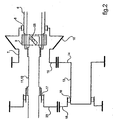
figure 2 illustre schématiquement en coupe axiale un mécanisme de transmission selon un deuxième exemple de réalisation de l'invention.
- The
figure 1 schematically illustrates in perspective a transmission mechanism according to a first embodiment of the invention. - The
figure 2 illustrates schematically in axial section a transmission mechanism according to a second embodiment of the invention.
Sur les figures, un mécanisme de transmission est organisé pour la motorisation d'accessoires 1,2 d'un giravion, tels qu'un alternateur 1 et un compresseur 2. On notera à ce stade de la description que ces accessoires 1,2, et leur situation dans le mécanisme, sont cités et illustrés pour exemple non limitatif quant à la portée de la présente invention. Ces accessoires 1,2 sont motorisés à partir de l'un 3 des organes moteurs d'un couple d'organes moteurs 3,4 du giravion destinés à l'entraînement du rotor 5. Ce mécanisme de transmission comprend un arbre moteur 6 en relation avec l'organe moteur 3 affecté à la motorisation des accessoires 1,2. Cet arbre moteur 6 est en relation avec un arbre principal 7 d'entraînement du rotor 5, par l'intermédiaire d'un organe principal 8 à différentiel de vitesses de rotation et par l'intermédiaire d'un organe 9 à entraînement sélectif de l'arbre principal 7 par l'arbre moteur 6.In the figures, a transmission mechanism is organized for the motorization of
L'arbre principal 7 est en relation avec le rotor 5 par l'intermédiaire d'une pignonerie, comprenant notamment un organe 10 d'entraînement du rotor 5 dont il est muni, tel qu'un pignon conique ou analogue.The main shaft 7 is in relation with the
Sur les exemples illustrés, l'arbre principal 7 est plus particulièrement monté coaxialement autour de l'arbre moteur 6, l'organe principal 8 à différentiel de vitesses de rotation étant constitué d'une roue libre principale interposée entre eux. L'organe à entraînement sélectif 9 est quant à lui interposé entre l'arbre moteur 6 et la roue libre 8, en étant manoeuvrable axialement par un organe 11 agencé en tringle axiale ou analogue. Cet organe à entraînement sélectif 9 est notamment constitué à la manière habituelle dans le domaine par un dispositif à crabot manoeuvrable par la tringle axiale 11, dont les détails connus ne sont pas représentés.In the illustrated examples, the main shaft 7 is more particularly mounted coaxially around the drive shaft 6, the main member 8 with a differential speed of rotation consisting of a main freewheel interposed between them. The selectively driving member 9 is interposed between the drive shaft 6 and the free wheel 8, being operable axially by a member 11 arranged in axial rod or the like. This selectively driving member 9 is in particular constituted in the usual manner in the field by a dog clutch device operable by the axial rod 11, whose known details are not shown.
L'arbre moteur 6 est par ailleurs en relation avec un arbre secondaire 12 pour l'entraînement des accessoires 1 et 2.The driving shaft 6 is also related to a
Sur l'exemple de réalisation illustré sur la
Sur l'exemple de réalisation illustré sur la
Les accessoires 1 et 2 sont en relation avec l'arbre principal 7 par l'intermédiaire d'une pignonerie comprenant un arbre intermédiaire 13. Ce dernier 13 est en prise directe sur l'arbre principal 7, par l'intermédiaire d'un jeu de pignons 14 et 15 ou analogues qui leurs sont affectés. Ce jeu de pignons comprend notamment un premier pignon 14, dont est muni l'arbre intermédiaire 13, qui est en prise sur un pignon d'entrée 15 de motorisation équipant l'arbre principal 7. L'arbre intermédiaire 13 est aussi en relation avec l'arbre secondaire 12 par l'intermédiaire d'un organe secondaire 16,17 à différentiel de vitesses de rotation et d'un pignon de sortie 23 de motorisation pour l'entraînement des accessoires 1 et 2.The
Cet organe secondaire à différentiel de vitesses de rotation est composé d'un jeu de roues libres secondaires 16,17 ou analogues. Une première roue libre secondaire 16 est interposée entre l'arbre intermédiaire 13 et un deuxième pignon 18 équipant ce dernier 13, tandis qu'une deuxième roue libre secondaire 17 est interposée entre le deuxième pignon 18 et l'arbre secondaire 12.This secondary member with differential rotation speeds is composed of a set of secondary
Sur la
Un tel agencement du mécanisme de transmission de la présente invention permet dans sa généralité de motoriser les accessoires 1 et 2 non seulement avec l'organe moteur 3 qui leur est directement affecté, mais aussi en cas de panne de ce dernier 3 avec l'autre organe moteur 4 d'entraînement du rotor 5, voire par le rotor 5 lui-même lorsqu'il est en autorotation en cas de pannes des organes moteurs 3 et 4 du giravion. On notera que le passage de l'une à l'autre de ces situations d'entraînement des accessoires 1 et 2 est autorisée sans avoir à interrompre l'entraînement de ces derniers, même momentanément. Cette faculté est offerte avec un surcroît de poids et d'encombrement réduits, et sans pour autant induire un changement des modalités habituelles de fonctionnement d'un tel mécanisme, au regard notamment des procédures de mise en relation entre l'arbre principal 7 et l'arbre moteur 6, et celles de mise en relation de l'arbre moteur 6 avec l'arbre d'entraînement secondaire 12.Such an arrangement of the transmission mechanism of the present invention allows in general its motorization
Plus précisément, en position de motorisation isolée, l'arbre intermédiaire 13 est immobilisé en rotation en raison de sa prise sur l'arbre principal 7 par l'intermédiaire du pignon conique 10. On comprendra par motorisation isolée la position selon laquelle les accessoires 1 et 2 sont entraînés en l'absence d'entraînement du rotor 5, lorsque l'appareil est en phase d'attente au sol notamment. L'arbre principal 7 est lui-même immobile en l'absence d'entraînement du rotor. Une telle immobilisation de l'arbre intermédiaire 13 ne fait néanmoins pas obstacle à l'entraînement de l'arbre secondaire 12 par l'arbre moteur 6. Suivant cette position de motorisation isolée, la roue libre 17 est montée sur l'arbre secondaire 12 de sorte qu'elle entraîne le pignon élémentaire 23. La roue libre 16 est quant à elle montée sur l'arbre intermédiaire 13 de manière glissante, pour permettre la rotation du deuxième pignon 18, en prise sur le pignon élémentaire 23, tandis que l'arbre intermédiaire 13 est immobilisé, en l'absence d'entraînement du rotor 5.More specifically, in the isolated drive position, the
Plus précisément encore en position de motorisation combinée, les vitesses relatives entre l'arbre principal 7 et l'arbre moteur 6 autorisant la manoeuvre axiale de l'organe 8 à entraînement sélectif au moyen de la tringle 11, l'arbre intermédiaire 13 et l'arbre secondaire 12 sont respectivement entraînés par l'arbre principal 7 et par l'arbre moteur 6. On comprendra par motorisation combinée la position selon laquelle les accessoires 1 et 2 sont entraînés simultanément avec le rotor 5, lui même conjointement entraîné par l'ensemble des organes moteurs 3 et 4. Suivant cette position de motorisation combinée, l'arbre secondaire 12 est entraîné par l'arbre moteur 6, tandis que l'arbre intermédiaire 13 est entraîné par le rotor 5 par l'intermédiaire de l'arbre principal 7 et des pignons 14 et 15, respectivement premier et d'entrée de motorisation.More precisely still in the combined drive position, the relative speeds between the main shaft 7 and the drive shaft 6 allowing the axial operation of the selectively driven member 8 by means of the rod 11, the
Il apparaît un choix astucieux du dimensionnement des rapports de transmission entre le pignon d'entrée de motorisation 15 et le premier pignon 14 d'une part, et entre le pignon de sortie 23 de motorisation et le deuxième pignon 18. En effet et compte tenu des différences d'inertie des organes tournants mis en oeuvre, notamment entre le rotor et les accessoires, et compte tenu d'éventuelles contraintes de seuils de fonctionnement minimum et maximum de l'un au moins des accessoires, il est souhaitable que le résultat de la multiplication entre les rapports susvisés soit de l'ordre de 1, en étant légèrement supérieur à cette valeur.It appears a clever choice of sizing transmission ratios between the
Plus précisément et selon un autre aspect de la présente invention, les rapports entre le pignon d'entrée 15 de motorisation et le premier pignon 14 d'une part, et entre le pignon de sortie de motorisation 23 et le deuxième pignon 18 d'autre part, répondent à la règle selon laquelle (Z15 / Z14) X (Z23 / Z18) est légèrement supérieur à 1, dans laquelle :
- Z15 est le nombre de dents du pignon d'entrée de motorisation.
- Z14 est le nombre de dents du premier pignon.
- Z23 est le nombre de dents du pignon de sortie de motorisation.
- Z18 est le nombre de dents du deuxième pignon.
- Z15 is the number of teeth of the motor input gear.
- Z14 is the number of teeth in the first gear.
- Z23 is the number of teeth of the motor output gear.
- Z18 is the number of teeth of the second gear.
Ces dispositions sont telles que pour la mise en oeuvre d'un tel mécanisme de transmission, le passage entre la position de motorisation isolée et la position de motorisation combinée, et inversement, s'effectue avec un léger différentiel de vitesse de rotation entre les vitesses de l'arbre moteur 6 et de l'arbre principal 7. Ce léger différentiel de vitesse est notamment obtenu à partir d'une légère diminution du régime de fonctionnement de l'organe moteur 3 affecté directement à la motorisation des accessoires, par rapport au régime de fonctionnement de l'organe 4 de motorisation indirecte des accessoires 1,2 par l'intermédiaire du rotor 5. Ces dispositions permettent une manoeuvre aisée de l'organe d'entraînement sélectif 9.These arrangements are such that for the implementation of such a transmission mechanism, the passage between the isolated motor position and the combined motor position, and vice versa, is performed with a slight differential speed of rotation between the speeds of the motor shaft 6 and the main shaft 7. This slight difference in speed is obtained in particular from a slight decrease in the speed of rotation. operation of the
On notera que le passage entre la position de motorisation isolée et la position de motorisation combinée et inversement peut être opéré sans interruption de la motorisation des accessoires 1 et 2, et que néanmoins en cas de rupture de l'entraînement de l'arbre secondaire 12 par l'arbre moteur 6, l'entraînement du pignon 23 est autorisé par l'intermédiaire de l'arbre intermédiaire 13 et de l'arbre principal 7 entraîné par le rotor 5, lui-même soit entraîné par l'organe 4 de motorisation indirecte des accessoires, soit en autorotation en cas de panne de ce dernier 3. On notera aussi que ces dispositions sont telles que la manoeuvre axiale de l'organe 8 à entraînement sélectif au moyen de la tringle 11 en est facilitée, à partir d'une exploitation des vitesses relatives de rotation entre les différents arbres 6,7,12, et 13 progressivement mises en harmonisation.It should be noted that the passage between the isolated motor position and the combined motor position and vice versa can be performed without interruption of the motorization of the
Plus précisément lors du passage de la position de motorisation isolée à celle de motorisation combinée, la manoeuvre de l'organe d'entraînement sélectif 9 est réalisée à faible différentiel de vitesse, pour éviter tout risque de rupture des organes en présence. Dans le cas où l'ensemble des organes moteurs 3 et 4 sont arrêtés, la manoeuvre de l'organe d'entraînement sélectif 9 est susceptible d'être effectuée directement, notamment par la manoeuvre de la tringle 11. Dans le cas où l'organe 3 de motorisation des accessoires 1 et 2 est en fonctionnement, son régime de fonctionnement est progressivement diminué. Il en ressort que le faible différentiel de vitesse entre l'arbre moteur 6 et l'arbre principal 7 autorise la manoeuvre de l'organe d'entraînement sélectif 9 sans risque de détérioration.More specifically, during the transition from the isolated drive position to that of the combined drive, the operation of the selective drive member 9 is performed at low speed differential, to avoid any risk of rupture of the bodies in the presence. In the case where all the
Plus précisément encore, lors du passage de la position de motorisation combinée à celle de motorisation isolée, le régime de l'organe 3 de motorisation des accessoires 1 et 2 est légèrement diminué pour permettre la manoeuvre inverse de l'organe d'entraînement sélectif 9.More precisely still, during the transition from the combined motor position to that of isolated motorization, the speed of the
On comprendra cependant que sans déroger aux règles qui ont été énoncées, il est visé par l'invention de permettre de procéder à un changement de motorisation des accessoires 1 et 2 à partir d'une légère variation de régime des organes de motorisation 3 et 4 l'un par rapport à l'autre, une diminution du régime de l'organe 3 de motorisation directe des accessoires 1 et 2 étant néanmoins préférée.It will be understood, however, that without derogating from the rules that have been set forth, it is the object of the invention to make it possible to carry out a motorization change of the
En cas de panne de l'organe 3 de motorisation des accessoires 1 et 2, le pignon de sortie 23 de motorisation est néanmoins entraîné par l'arbre intermédiaire 13, en prise sur l'arbre principal 7 lui-même entraîné en rotation par le rotor 5. Cet entraînement est plus particulièrement obtenu par la liaison successive entre l'arbre principal 7 et le pignon d'entrée 15 de motorisation dont il est équipé, avec le premier pignon élémentaire 14 et donc l'arbre intermédiaire 13 qui le supporte, puis avec le deuxième pignon 18 et le pignon de sortie 23 de motorisation par l'intermédiaire de l'organe secondaire 16 et 17 à différentiel de rotation, notamment constitué par un jeu de roues libre à osselets ou analogue par exemple.In the event of a breakdown of the
On relèvera que le dispositif de transmission de la présente invention est relié à un seul pignon 10 d'entraînement du rotor 5, nonobstant la présence de plusieurs organes moteurs 3 et 4 utilisés pour la motorisation de ce dernier. Il en ressort que le dispositif de transmission de la présente invention est susceptible d'être installé sur l'un des côtés de l'appareil, avec les avantages procurés relatifs notamment à son encombrement et à sa simplicité de structure.It will be noted that the transmission device of the present invention is connected to a
Claims (10)
- A transmission mechanism between at least one accessory (1,2) and engine members (3, 4) for driving a rotor (5) of a rotorcraft, a first engine member (3) being allocated to driving the accessory (1, 2) in isolation or together with the rotor (5), and a second engine member (4) being provided for driving only the rotor (5), this mechanism comprising a main shaft (7) provided with a drive member (10) for the rotor (5), the main shaft being associated with a drive shaft (6) engaged with the first engine member (3) via a main rotary speed differential member (8) and a selective rotary drive member (9), the selective rotary drive member (9) being movable between a position for combined drive of the accessory (1, 2) and the rotor (5) in which the main shaft (7) engages the drive shaft (6), and an isolated drive position in which the main shaft (7) does not engage the drive shaft (6) so as to drive the accessory (1, 2) alone, the accessory (1, 2) being engaged via gearing with a secondary shaft (12) associated with the drive shaft (6) of the first engine member (3), in which said gearing comprises at least one intermediate shaft (13) interposed between the main shaft (7) and the secondary shaft (12), the intermediate shaft (13) directly engaging the main shaft (7) and engaging the secondary shaft (12), a second rotary speed differential member (16, 17) being interposed between the secondary shaft (12) and the intermediate shaft (13) to enable the accessories (1, 2) to be driven either by the secondary shaft (12) alone, driven by the drive shaft (6) in the isolated drive position, or else by the intermediate shaft (13) driven by the main shaft (7), and in which the main shaft (7) is mounted coaxially to the drive shaft (6), the selective drive member (9) being interposed between the drive shaft (6) and the main rotary speed differential member (8), the mechanism comprising an axial rod (11) for moving the selective drive member (9).
- A mechanism according to claim 1, in which the intermediate shaft (13) is fitted with a first gear (14) engaged with a drive inlet gear (15) fitted on the main shaft (17), and with a second gear (18) engaging firstly with the secondary shaft (12) via the secondary speed differential member, and secondly engaging with a drive outlet gear (23) for driving the accessories (1, 2).
- A mechanism according to claim 2, in which the secondary speed differential member (16, 17) comprises a pair of secondary freewheels interposed between the second gear (18) and the intermediate shaft (13) for a first secondary freewheel (16), and between the drive outlet gear (23) and the secondary shaft (12) for a second secondary freewheel (17) .
- A mechanism according to any one of claims 2 or 3, in which the ratio between the drive inlet gear (15) and the first gear (14) on one hand, and the ratio between the drive outlet gear (23) and the second gear (18) on the other hand satisfy the following inequality

in which:- Z 15 is the number of teeth on the drive inlet gear;- Z14 is the number of teeth on the first gear;- Z23 is the number of teeth on the drive outlet gear; and- Z18 is the number of teeth on the second gear. - A mechanism according to any one of the preceding claims, in which the main shaft (7) is mounted coaxially around the drive shaft (6), the main rotary speed differential member (8) being constituted essentially by a main freewheel interposed between them.
- A mechanism according to any one of claims 1 to 5, in which the secondary shaft (12) is coaxial to the drive shaft (6) which it extends, the drive shaft (6) extending at least in part inside the main shaft (7) and receiving the rod (11) which emerges at its end opposite from its end extending the drive shaft (6).
- A mechanism according to any one of claims 1 to 5, in which the secondary shaft (12) and the rod (11) for moving the selective drive member (9) coincide, the rod (11) being associated with the intermediate shaft (13) via the secondary rotary speed differential member (16, 17) and having, at its distal end opposite from its end used for moving it, a control member (25) for moving the selective drive member (9).
- A mechanism according to any one of the preceding claims, in which a first individual shaft (19) for driving the accessories (1, 2) is engaged on the secondary shaft (12) while a second individual shaft (20) for driving the accessories (1, 2) is engaged on the intermediate shaft (13).
- A mechanism according to claim 4, in which the passage between the isolated drive position and the combined drive position is performed with a rotary speed differential between the speed of the drive shaft (6) and the speed of the main shaft (7).
- A mechanism according to claim 4, in which the passage between the isolated drive position and the combined drive position is performed by reducing the operating speed of the first engine member (3) relative to the operating speed of the second engine member (4) in order to make it easy to move the selective drive member (9).
Applications Claiming Priority (2)
| Application Number | Priority Date | Filing Date | Title |
|---|---|---|---|
| FR0406131A FR2871138B1 (en) | 2004-06-07 | 2004-06-07 | TRANSMISSION MECHANISM BETWEEN ACCESSORIES AND ROTOR DRIVE ENGINE ORGANS OF A ROTOR, SELECTIVELY ISOLATED OR JOINTLY |
| PCT/FR2005/001319 WO2006005830A1 (en) | 2004-06-07 | 2005-06-01 | Transmission mechanism between accessories and motoring members, driving a rotorcraft rotor, selectively, individually or jointly |
Publications (2)
| Publication Number | Publication Date |
|---|---|
| EP1753657A1 EP1753657A1 (en) | 2007-02-21 |
| EP1753657B1 true EP1753657B1 (en) | 2008-08-13 |
Family
ID=34945623
Family Applications (1)
| Application Number | Title | Priority Date | Filing Date |
|---|---|---|---|
| EP05773025A Ceased EP1753657B1 (en) | 2004-06-07 | 2005-06-01 | Transmission mechanism between accessories and motoring members, driving a rotorcraft rotor, selectively, individually or jointly |
Country Status (8)
| Country | Link |
|---|---|
| US (1) | US7418888B2 (en) |
| EP (1) | EP1753657B1 (en) |
| JP (1) | JP4414462B2 (en) |
| KR (1) | KR100843307B1 (en) |
| CN (1) | CN100482537C (en) |
| DE (1) | DE602005008952D1 (en) |
| FR (1) | FR2871138B1 (en) |
| WO (1) | WO2006005830A1 (en) |
Cited By (1)
| Publication number | Priority date | Publication date | Assignee | Title |
|---|---|---|---|---|
| CN104061284A (en) * | 2014-06-23 | 2014-09-24 | 深圳市高士通科技有限公司 | T-shaped secondary speed reducer for unmanned helicopter |
Families Citing this family (21)
| Publication number | Priority date | Publication date | Assignee | Title |
|---|---|---|---|---|
| US20050025825A1 (en) * | 2003-07-31 | 2005-02-03 | Xanodyne Pharmacal, Inc. | Tranexamic acid formulations with reduced adverse effects |
| US8022106B2 (en) | 2004-03-04 | 2011-09-20 | Ferring B.V. | Tranexamic acid formulations |
| US20050244495A1 (en) | 2004-03-04 | 2005-11-03 | Xanodyne Pharmaceuticals, Inc. | Tranexamic acid formulations |
| US20050245614A1 (en) * | 2004-03-04 | 2005-11-03 | Xanodyne Pharmaceuticals, Inc. | Tranexamic acid formulations |
| ES2702125T3 (en) * | 2005-06-23 | 2019-02-27 | Ital Res & Innovation S R L | Combined multipurpose machine |
| AU2006318319B2 (en) * | 2005-11-18 | 2013-01-17 | Glaxo Group Limited | Machine and method for pharmaceutical and pharmaceutical-like product assembly |
| US7536927B2 (en) * | 2006-06-05 | 2009-05-26 | Brose Fahrzeugteile GmbH & Co. Kommanditgesellschaft, Würzburg | Window lift drive for raising and lowering windows in a vehicle door |
| FR2928192B1 (en) * | 2008-02-28 | 2010-03-19 | Eurocopter France | POWER TRANSMISSION BOX HAVING AN ALTERNATIVE ROTATION SPEED AND CORRESPONDING METHOD OF OPERATION |
| WO2009111724A1 (en) * | 2008-03-06 | 2009-09-11 | Karem Aircraft, Inc. | Torque balancing gearbox |
| US8133155B2 (en) * | 2009-07-14 | 2012-03-13 | Bell Helicopter Textron Inc. | Multi-ratio rotorcraft drive system and a method of changing gear ratios thereof |
| EP2653751A1 (en) * | 2012-04-17 | 2013-10-23 | Siemens Aktiengesellschaft | Gear motor series |
| FR2992630B1 (en) * | 2012-06-29 | 2015-02-20 | Turbomeca | METHOD AND CONFIGURATION OF PROPULSIVE AND / OR NON-PROPULSIVE ENERGY DELIVERY IN A HELICOPTER ARCHITECTURE BY A POWER AUXILIARY ENGINE |
| EP2818419B1 (en) * | 2013-06-27 | 2017-04-12 | Airbus Defence and Space Limited | A rotatable assembly |
| ITVR20130272A1 (en) * | 2013-12-09 | 2015-06-10 | Siral S R L | SPEED EXCHANGE DEVICE FOR MEANS OF TRANSPORT |
| FR3019247B1 (en) * | 2014-03-27 | 2017-09-01 | Turbomeca | TRANSMISSION ASSEMBLY FOR AIRCRAFT AND HELICOPTER |
| CN104864073A (en) * | 2015-05-08 | 2015-08-26 | 博艳萍 | Bi-directional mounting-type gear-driving mechanism |
| CN104960664A (en) * | 2015-05-26 | 2015-10-07 | 北京理工大学 | Composite jump takeoff system for heavy gyroplane with jump takeoff capability |
| FR3055934B1 (en) * | 2016-09-09 | 2018-08-17 | Airbus Helicopters | MECHANICAL SYSTEM FOR TRANSMITTING A MOVEMENT AND AIRCRAFT EQUIPPED WITH A CORRESPONDING SYSTEM |
| FR3055883B1 (en) * | 2016-09-09 | 2019-03-29 | Airbus Helicopters | MECHANICAL SYSTEM FOR TRANSMITTING A MOVEMENT AND AIRCRAFT EQUIPPED WITH A CORRESPONDING SYSTEM |
| FR3072944B1 (en) * | 2017-10-26 | 2019-10-11 | Airbus Helicopters | METHOD AND DEVICE FOR OPTIMIZING POWER IN A POWER PLANT |
| FR3147793A1 (en) | 2023-04-13 | 2024-10-18 | Airbus Helicopters | method of piloting a multi-engine rotary wing aircraft with reduced fuel consumption on the ground |
Family Cites Families (16)
| Publication number | Priority date | Publication date | Assignee | Title |
|---|---|---|---|---|
| US2979968A (en) * | 1958-08-28 | 1961-04-18 | United Aircraft Corp | Power transmission system |
| FR1325704A (en) * | 1962-03-14 | 1963-05-03 | Sud Aviation | Further development of gearboxes for single-rotor helicopters with several turbines |
| GB1389403A (en) * | 1971-06-01 | 1975-04-03 | Westland Aircraft Ltd | Helicopter power transmission systems |
| IT1179663B (en) | 1984-05-14 | 1987-09-16 | Agusta Aeronaut Costr | MAIN TRANSMISSION FOR HELICOPTERS |
| FR2568541B1 (en) * | 1984-08-06 | 1987-03-20 | Aerospatiale | MAIN TRANSMISSION BOX FOR TWIN-MOTOR HELICOPTER |
| GB8625712D0 (en) * | 1986-10-28 | 1987-03-18 | Westland Plc | Transmission system |
| US5108043A (en) * | 1991-03-29 | 1992-04-28 | Bell Helicopter Textron, Inc. | Twin engine helicopter accesssory drive |
| CN1025951C (en) * | 1992-05-30 | 1994-09-21 | 李晓阳 | Transmission differential mechanism of coaxial rotor craft |
| US5281099A (en) * | 1992-06-22 | 1994-01-25 | United Technologies Corporation | Integrated spline/cone seat subassembly for a rotor assembly having ducted, coaxial counter-rotating rotors |
| IT1261872B (en) * | 1993-09-17 | 1996-06-03 | Fiatavio Spa | APPLICATION OF FACIAL GEARS FOR TRANSMISSIONS FOR HELICOPTERS. |
| US5472386A (en) * | 1994-05-26 | 1995-12-05 | United Technologies Corporation | Stacked compound planetary gear train for an upgraded powertrain system for a helicopter |
| JP3029976B2 (en) * | 1995-01-27 | 2000-04-10 | 株式会社コミュータヘリコプタ先進技術研究所 | Helicopter power transmission |
| JP3029981B2 (en) * | 1995-04-27 | 2000-04-10 | 株式会社コミュータヘリコプタ先進技術研究所 | Helicopter power transmission |
| US5802918A (en) * | 1996-10-16 | 1998-09-08 | Mcdonnell Douglas Helicopter Co. | Concentric face gear transmission assembly |
| US5853145A (en) * | 1997-01-09 | 1998-12-29 | Cartercopters, Llc | Rotor head for rotary wing aircraft |
| US6443035B1 (en) * | 2001-09-20 | 2002-09-03 | The Boeing Company | Hybrid power input quill for transmissions |
-
2004
- 2004-06-07 FR FR0406131A patent/FR2871138B1/en not_active Expired - Fee Related
-
2005
- 2005-06-01 EP EP05773025A patent/EP1753657B1/en not_active Ceased
- 2005-06-01 JP JP2007514021A patent/JP4414462B2/en not_active Expired - Fee Related
- 2005-06-01 WO PCT/FR2005/001319 patent/WO2006005830A1/en not_active Ceased
- 2005-06-01 KR KR1020067024935A patent/KR100843307B1/en not_active Expired - Lifetime
- 2005-06-01 CN CNB200580018110XA patent/CN100482537C/en not_active Expired - Fee Related
- 2005-06-01 DE DE602005008952T patent/DE602005008952D1/en not_active Expired - Lifetime
- 2005-06-07 US US11/145,928 patent/US7418888B2/en active Active
Cited By (2)
| Publication number | Priority date | Publication date | Assignee | Title |
|---|---|---|---|---|
| CN104061284A (en) * | 2014-06-23 | 2014-09-24 | 深圳市高士通科技有限公司 | T-shaped secondary speed reducer for unmanned helicopter |
| CN104061284B (en) * | 2014-06-23 | 2016-10-26 | 深圳市高士通科技有限公司 | The T-shaped two stage reducer of depopulated helicopter |
Also Published As
| Publication number | Publication date |
|---|---|
| US20060000300A1 (en) | 2006-01-05 |
| CN1964888A (en) | 2007-05-16 |
| US7418888B2 (en) | 2008-09-02 |
| EP1753657A1 (en) | 2007-02-21 |
| KR100843307B1 (en) | 2008-07-04 |
| FR2871138A1 (en) | 2005-12-09 |
| JP2008501564A (en) | 2008-01-24 |
| JP4414462B2 (en) | 2010-02-10 |
| KR20070020050A (en) | 2007-02-16 |
| CN100482537C (en) | 2009-04-29 |
| DE602005008952D1 (en) | 2008-09-25 |
| WO2006005830A1 (en) | 2006-01-19 |
| FR2871138B1 (en) | 2006-08-04 |
Similar Documents
| Publication | Publication Date | Title |
|---|---|---|
| EP1753657B1 (en) | Transmission mechanism between accessories and motoring members, driving a rotorcraft rotor, selectively, individually or jointly | |
| EP2512855B1 (en) | Motorised hub with coupling/decoupling means | |
| EP3034397B1 (en) | System for motorising a wheel connected to a suspension | |
| EP2431274B1 (en) | Rotary wing aircraft with propulsion means and a method applied by said aircraft. | |
| EP1845016B1 (en) | Landing gear comprising several electromechanical direction actuators | |
| EP0224407B1 (en) | Gear transmission with one input shaft and two counter shafts | |
| EP1541834A1 (en) | Power take-off for the accessories of a twin spool turbo-jet engine | |
| WO2015052430A1 (en) | Turbomachine auxiliary drive gearbox | |
| FR2973334A1 (en) | HIGH INTEGRITY ROTARY ACTUATOR AND CONTROL METHOD | |
| FR2954236A1 (en) | Coaxial wheel motorization system for main landing gear in airplane, has clutch device connecting output shaft of motor block to driving element, where motor block comprises electric motor arranged in axle crosspiece of wheel | |
| EP0227503A1 (en) | Convertible gear box with parallel axes and a planetary gear train, especially for motor vehicles | |
| FR2939763A1 (en) | Front landing gear for aircraft, has wheel provided with rim, hub for carrying rim, and motor and reducer that are completely received in hub for driving of wheel, where motor or reducer is arranged between axis of hub and brake of wheel | |
| EP2174868A1 (en) | Device for driving first and second main rotors of a tandem birotor helicopter | |
| EP3176469B1 (en) | Steering system with low-bulk mechanical differential | |
| WO2014013084A1 (en) | Motorized hub comprising a change in ratio and coupling and uncoupling means | |
| WO2023209291A1 (en) | Accessory gearbox and aircraft turbine engine comprising such a box | |
| EP3293111B1 (en) | A mechanical motion transmission system and an aircraft fitted with a corresponding system | |
| FR2966786A3 (en) | HYBRID MOTORIZATION SYSTEM FOR MOTOR VEHICLE | |
| FR3013262A1 (en) | ENGINE GROUP FOR EQUIPPING A CONVERTIBLE AIRCRAFT | |
| EP0819864B1 (en) | Compact synchronizer for a gearbox, especially for a motorvehicle | |
| FR3008955A1 (en) | DEVICE FOR DRIVING ROTATION OF AN AIRCRAFT WHEEL | |
| EP1097317A1 (en) | Transmission unit with reversing mechanism mounted between a gearbox and at least two drive wheels | |
| FR2683013A1 (en) | MODULAR TRANSMISSION DEVICE AND MOTOR-PROPELLER UNIT THUS EQUIPPED. | |
| FR2929562A1 (en) | Light weight vehicle i.e. tricycle, for e.g. leisure activity, has pinions substituting differential, where each pinion transmits entire or fraction of torque to wheels, when speed of driven part is not greater than speed of driving part | |
| US20100173741A1 (en) | Method of altering a drive ratio on a driven wheel and a drive assembly in accordance with the method |
Legal Events
| Date | Code | Title | Description |
|---|---|---|---|
| PUAI | Public reference made under article 153(3) epc to a published international application that has entered the european phase |
Free format text: ORIGINAL CODE: 0009012 |
|
| 17P | Request for examination filed |
Effective date: 20061025 |
|
| AK | Designated contracting states |
Kind code of ref document: A1 Designated state(s): DE GB IT |
|
| TPAC | Observations filed by third parties |
Free format text: ORIGINAL CODE: EPIDOSNTIPA |
|
| DAX | Request for extension of the european patent (deleted) | ||
| RBV | Designated contracting states (corrected) |
Designated state(s): DE GB IT |
|
| GRAP | Despatch of communication of intention to grant a patent |
Free format text: ORIGINAL CODE: EPIDOSNIGR1 |
|
| GRAS | Grant fee paid |
Free format text: ORIGINAL CODE: EPIDOSNIGR3 |
|
| GRAA | (expected) grant |
Free format text: ORIGINAL CODE: 0009210 |
|
| AK | Designated contracting states |
Kind code of ref document: B1 Designated state(s): DE GB IT |
|
| REG | Reference to a national code |
Ref country code: GB Ref legal event code: FG4D Free format text: NOT ENGLISH |
|
| REF | Corresponds to: |
Ref document number: 602005008952 Country of ref document: DE Date of ref document: 20080925 Kind code of ref document: P |
|
| PLBE | No opposition filed within time limit |
Free format text: ORIGINAL CODE: 0009261 |
|
| STAA | Information on the status of an ep patent application or granted ep patent |
Free format text: STATUS: NO OPPOSITION FILED WITHIN TIME LIMIT |
|
| 26N | No opposition filed |
Effective date: 20090514 |
|
| REG | Reference to a national code |
Ref country code: DE Ref legal event code: R082 Ref document number: 602005008952 Country of ref document: DE Representative=s name: GPI & ASSOCIES, FR |
|
| REG | Reference to a national code |
Ref country code: DE Ref legal event code: R082 Ref document number: 602005008952 Country of ref document: DE Representative=s name: GPI & ASSOCIES, FR Ref country code: DE Ref legal event code: R081 Ref document number: 602005008952 Country of ref document: DE Owner name: AIRBUS HELICOPTERS, FR Free format text: FORMER OWNER: EUROCOPTER, MARIGNANE, FR |
|
| PGFP | Annual fee paid to national office [announced via postgrant information from national office to epo] |
Ref country code: GB Payment date: 20200625 Year of fee payment: 16 |
|
| PGFP | Annual fee paid to national office [announced via postgrant information from national office to epo] |
Ref country code: DE Payment date: 20210618 Year of fee payment: 17 |
|
| GBPC | Gb: european patent ceased through non-payment of renewal fee |
Effective date: 20210601 |
|
| PG25 | Lapsed in a contracting state [announced via postgrant information from national office to epo] |
Ref country code: GB Free format text: LAPSE BECAUSE OF NON-PAYMENT OF DUE FEES Effective date: 20210601 |
|
| PGFP | Annual fee paid to national office [announced via postgrant information from national office to epo] |
Ref country code: IT Payment date: 20220627 Year of fee payment: 18 |
|
| REG | Reference to a national code |
Ref country code: DE Ref legal event code: R119 Ref document number: 602005008952 Country of ref document: DE |
|
| PG25 | Lapsed in a contracting state [announced via postgrant information from national office to epo] |
Ref country code: DE Free format text: LAPSE BECAUSE OF NON-PAYMENT OF DUE FEES Effective date: 20230103 |
|
| PG25 | Lapsed in a contracting state [announced via postgrant information from national office to epo] |
Ref country code: IT Free format text: LAPSE BECAUSE OF NON-PAYMENT OF DUE FEES Effective date: 20230601 |