EP1753629B1 - Arbeitsmaschinen-vollreifen mit elastischem körper - Google Patents
Arbeitsmaschinen-vollreifen mit elastischem körper Download PDFInfo
- Publication number
- EP1753629B1 EP1753629B1 EP05735517A EP05735517A EP1753629B1 EP 1753629 B1 EP1753629 B1 EP 1753629B1 EP 05735517 A EP05735517 A EP 05735517A EP 05735517 A EP05735517 A EP 05735517A EP 1753629 B1 EP1753629 B1 EP 1753629B1
- Authority
- EP
- European Patent Office
- Prior art keywords
- cavities
- work machine
- tire
- radial
- band
- Prior art date
- Legal status (The legal status is an assumption and is not a legal conclusion. Google has not performed a legal analysis and makes no representation as to the accuracy of the status listed.)
- Expired - Lifetime
Links
- 239000007787 solid Substances 0.000 title description 13
- 239000000463 material Substances 0.000 claims abstract description 53
- 239000011800 void material Substances 0.000 claims abstract description 35
- 239000013536 elastomeric material Substances 0.000 claims abstract description 7
- 230000004888 barrier function Effects 0.000 claims description 7
- 229920001971 elastomer Polymers 0.000 description 12
- 239000005060 rubber Substances 0.000 description 10
- 230000002441 reversible effect Effects 0.000 description 6
- 238000005452 bending Methods 0.000 description 5
- 230000000750 progressive effect Effects 0.000 description 4
- 238000007906 compression Methods 0.000 description 3
- 230000006835 compression Effects 0.000 description 3
- 230000000670 limiting effect Effects 0.000 description 3
- 230000001133 acceleration Effects 0.000 description 2
- 239000000806 elastomer Substances 0.000 description 2
- 239000000203 mixture Substances 0.000 description 2
- 229920003052 natural elastomer Polymers 0.000 description 2
- 229920001194 natural rubber Polymers 0.000 description 2
- 230000036961 partial effect Effects 0.000 description 2
- 229920003051 synthetic elastomer Polymers 0.000 description 2
- 244000043261 Hevea brasiliensis Species 0.000 description 1
- 230000001351 cycling effect Effects 0.000 description 1
- 230000003247 decreasing effect Effects 0.000 description 1
- 238000006073 displacement reaction Methods 0.000 description 1
- 239000006263 elastomeric foam Substances 0.000 description 1
- 238000005188 flotation Methods 0.000 description 1
- 238000009472 formulation Methods 0.000 description 1
- 238000004519 manufacturing process Methods 0.000 description 1
- 238000000034 method Methods 0.000 description 1
- 238000000465 moulding Methods 0.000 description 1
- 229920002635 polyurethane Polymers 0.000 description 1
- 239000004814 polyurethane Substances 0.000 description 1
- 230000002829 reductive effect Effects 0.000 description 1
- 239000012265 solid product Substances 0.000 description 1
- 239000005061 synthetic rubber Substances 0.000 description 1
Images


Classifications
-
- B—PERFORMING OPERATIONS; TRANSPORTING
- B60—VEHICLES IN GENERAL
- B60C—VEHICLE TYRES; TYRE INFLATION; TYRE CHANGING; CONNECTING VALVES TO INFLATABLE ELASTIC BODIES IN GENERAL; DEVICES OR ARRANGEMENTS RELATED TO TYRES
- B60C7/00—Non-inflatable or solid tyres
- B60C7/10—Non-inflatable or solid tyres characterised by means for increasing resiliency
- B60C7/107—Non-inflatable or solid tyres characterised by means for increasing resiliency comprising lateral openings
Definitions
- the present disclosure relates generally to work machine tires, and more specifically to non-pneumatic work machine tires.
- work machine tires can be non-pneumatic, and thus, are comprised of solid or semi-solid products.
- the non-pneumatic work machine tires are more durable than pneumatic tires, the non-pneumatic tires are often too stiff to provide a smooth ride and lack the contact area with the ground to provide relatively good traction.
- some non-pneumatic tires include a radial band of unpressurized cavities, or recesses. The radial band lessens the stiffness and increases the deformation of the tire so it will ride better than a solid tire.
- Such a tire is sold by MITL under a trademark that suggests flexibility, but it still provides a stiff ride more similar to a solid tire than a pneumatic tire.
- the non-pneumatic tire described in U.S. Patent Number 5,042,544 corresponding with the preamble of claim 1, issued to Dehasse, on 27 August 1991 defined a radial band of recesses that enable the tire to deform due to a load and provides an area of contact with the road that is supposedly similar to that provided by a pneumatic tire.
- the recesses of the Dehasse non-pneumatic tire are taught as being intrinsically dissymmetrical to any radial direction and overlap one another.
- the Dehasse non-pneumatic tire uses recesses in order to control the tire performance and road handling, the Dehasse tire is intended to have a weight and bulk similar to that of pneumatic tires. Thus, the Dehasse tire would not possess the durability required for high load, low speed work machine applications.
- the present disclosure is directed at overcoming one or more of the problems set forth above.
- a work machine tire includes an annular body of elastomeric material.
- a radial middle region of the elastomeric material defines a plurality of unpressurized cavities distributed in a pattern that includes a first radially inner band of cavities and a second radially outer band of cavities.
- Each cavity of the first radial band of cavities is oriented at a positive angle with respect to a radius therethrough, and each cavity of the second radial band of cavities is oriented at a negative angle with respect to a radius therethrough.
- a material volume of the radial middle region is more than one and a half times greater than a combined void volume of the plurality of unpressurized cavities.
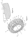
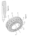
- FIG. 1 there is shown an isometric view of a work machine tire 10, according to a preferred embodiment of the present disclosure.
- all work machine tires 10, 110, 210, 310, 410 and 510 illustrated in the six embodiments are 31 inch diameter tires designed for a skid steer loader, those skilled in the art will appreciate that the present disclosure contemplates tires of various sizes that can be used with other various work machines, preferably with relatively small work machines, such as small wheel loaders, backhoe loaders and maybe trucks, but other larger work machines are still suitable.
- the work machine tire 10 includes an annular body 11 of elastomeric material.
- annular body 11 could be made from various elastomeric materials, the annular body 11 is illustrated as being made from rubber of any suitable tire formulation known in the art.
- tire 10 might be molded from a natural rubber or a natural/synthetic rubber blend having a Young's Modulus between 1 MPa and 6 MPa at 100% elongation.
- a 100% tensile modulus of about 2.75 MPa is used.
- Fully synthetic elastomers, such as polyurethanes could also be used.
- the annular body 11 includes a radial middle region 12, and preferably a radial outer region 13 and a radial inner region 14, both of which are adjacent to the radial middle region 12.
- the radial inner region 14 attaches to a wheel hub in a conventional manner, such as by being directly bonded thereto, and the wheel is attached to the work machine.
- the radial outer region includes the tread.
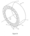
- the radial outer region 13 and the radial inner region 14 are preferably, but not necessarily cavity-free, and the radial middle region 12 defines a plurality of unpressurized cavities 15 that are distributed in a pattern that includes a first radial band of cavities 16 and a second radial band of cavities 17.
- the bands may or may not overlap, depending upon the desired properties of the particular application.
- the cavities 15 are evenly spaced throughout each radial band 16 and 17.
- Each cavity within the first radial band of cavities 16 is oriented at a positive angle with respect to a radius therethrough, and each cavity within the second radial band of cavities 17 is oriented at a negative angle with respect to a radius therethrough.
- the first and second radial bands of cavities 16 and 17 are oriented at opposing angles in order to cancel or reduce any torsional stiffness bias created by each radial band of cavities 16 and 17. Without the first radial band of cavities 16 canceling the torsional stiffness bias of the second radial band of cavities 17, and vice versa, a tangential force acting in a forward direction on the work machine tire 10, when compared with the reverse direction, might cause a significantly different degree of rotation of an outer portion of the work machine tire 10 to rotate with respect to an inner portion. This could result in unpredictable work machine motion during acceleration, stopping, pulling, pushing, digging, or any other work cycle that could produce a tangential force on the tire.
- the positive angle is 63° and the negative angle is 52° with respect to a radial line through the center of the cavity.
- the positive and negative angles can vary, and are determined based on various factors, including but not limited to, the size and shape of cavities within the first radial band and the second radial band.
- the positive angle of the first radial band 16 is preferably different than the negative angle of the second radial band 17, those skilled in the art will appreciate that the positive angle and the negative angle could be the same.
- the shape and/or size and/or number of the cavities within the first radial band may need to be different than the shape and/or size and/or number of cavities in the second radial band in order to generate similar performance.
- the number of cavities is preferably proportional to the diameter of the tire.
- the work machine tire 10 includes less than fifty unpressurized cavities 15.
- the work machine tire 10 includes forty unpressurized cavities 15, with twenty unpressurized cavities within each of the first and second radial bands 16 and 17.
- each of the unpressurized cavities within the plurality 15 have an axis of symmetry parallel to a tire axis of rotation 18.
- the plurality of unpressurized cavities 15 preferably have a uniform shape and volume, it should be appreciated that the first radial band of cavities could have a different shape than the second radial band of cavities.
- the shape and/or size of the first radial band may differ from the shape and/or sizes of the second radial band.
- the uniform shape illustrated includes a cross-sectional shape with a perimeter 25 that includes a pair of straight wall portions 25 a separated by a pair of arches 25b.
- the length and width of the cross-sectional shape can vary depending on various factors, including but not limited to, the desired combined void volume. In the preferred embodiment, the length of the cavities 15 is illustrated as approximately 2.3 inches, the width is approximately 0.9 inch, and the depth is approximately 4.9 inches if extending half the tire width, but may be 9.8 inches if extending the full width of the tire.
- FIG. 1a there is shown a cross-sectioned view of the radial outer region 13 of the work machine tire 10.
- the radial outer region 13 includes an exposed off-road tread pattern 21 that has a depth 22, which is the distance between a base 23 and a top 24 of the tread 21.
- the view of Fig. 1a and similar views in the other drawings show the theoretical intersection of the side profile and the crown at the comers; it may not reflect the maximum diametrical location on the tire. Although maximum tread depth is desirable for traction and wear purposes, the tread depth 22 is limited by the overall desired diameter of the tire 10.
- the tread depth 22 is typically a compromise between the desired traction, stiffness and rubber strain of the tire 10.
- the depth 22 of the off-road tread pattern 21 is at least one inch. In the preferred embodiment illustrated in Figure 1a , the off-road tread is 1.74 inches deep. Those skilled in the art will appreciate that the off-road tread 21 should be sufficient for the operation of work machine tire 10 in off-road environments.
- the radial middle region 12 includes a material volume, and the plurality of unpressurized cavities 15 have a combined void volume.
- radial middle region is bounded by an inner diameter that is tangent to the inner band of cavities 16, and bounded by an outer diameter tangent to the outer band of cavities 17.
- a ratio of the material volume to the combined void volume may vary, the material volume is more than one and a half times greater than a combined void volume of the plurality of unpressurized cavities 15.
- the material volume of the middle radial region 12 is about twice the combined void volume.
- the cavities 15 within the tire 10 lessen the stiffness of the tire 10 in order to provide deflection and a relatively smooth ride for the operator the load and the work machine. Moreover, the cavities 15 permit the material to deflect by bending, rather than by either pure compression or stretching, thereby limiting the material strain while permitting substantial deflections. However, the work machine tire 10 must include sufficient material in order to carry the loads to which the work machine is subjected. Thus, the determination of the material volume to the combined void volume ratio is a compromise between various known factors, including but not limited to the desired stiffness and strain and durability of the work machine tire.
- each cavity within the plurality 115 includes a length of 2.2 inches, a width of 0.9 inch, and a depth of 4.9 inches for halfway through (9.8 inches if full width of tire).
- the radial outer region 113 includes an exposed off-road tread pattern 121 that has a depth 122 defined as the distance between a base 123 of the tread 121 and a top 124 of the tread 121.
- the depth 22 of the off-road tread pattern 21 of Figure 1 was 1.74 inches
- the depth 122 of the off-road tread pattern 121 of the second embodiment is 1.98 inches.
- the work machine tire 10 can support a thicker off-road tread 121 than in the preferred embodiment.
- the higher material volume to void volume ratio may result in an increased stiffness that can affect the smoothness of the work machine ride.
- a work machine tire 210 is similar to the work machine tires 10 and 110 of the preferred and second embodiments except that a material volume to a combined void volume ratio of the work machine 210 is less than that of the preferred and the second embodiments.
- a radial middle region 212 of the work machine tire 210 includes the material volume that is 1.8 times greater (which is still about twice) than the combined void volume of the plurality of cavities 215.
- Each cavity within the plurality 215 includes a length of 2.3 inches, a width of 1.1 inches, and a depth of 4.9 inches for half way through (9.8 inches if full width of tire).
- the radial outer region 213 includes an exposed off-road tread 221 that includes a depth 222 defined as the distance between a base 223 and a top 224 of the tread 221.
- the depth 222 of the tread 221 is 1.54 inches.
- the work machine tire 310 includes an annular body 311 that includes a radial middle region 312 adjacent to a preferably cavity-free radial inner region 14 and a preferably cavity-free radial outer region 313.
- the radial middle region 312 defines a plurality of unpressurized cavities 315 that include that a first radial band of cavities 316 that are oriented at a positive angle with respect to a radius therethrough and a second radial band of cavities 317 that are oriented at a negative angle with respect to a radius therethrough.
- the tires 10, 110 and 210 of the first, second and third embodiments include twenty cavities in each radial band 16, 116, 216 and 17, 117, 217
- the work machine 310 defines eighteen cavities in each of the first and second radial bands 316 and 317, for a total of thirty-six cavities within the plurality 315.
- a material volume of the radial middle region 312 is 2.6 times a combined void volume of the plurality of cavities 315.
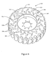
- the work machine tire 410 includes an annular body 411 that includes a radial middle region 412 adjacent to a preferably cavity-free radial inner region 14 and a preferably cavity-free radial outer region 413.
- the radial middle region 412 defines a plurality of unpressurized cavities 415 that include that a first radial band of cavities 416 that are oriented at a positive angle with respect to a radius therethrough and a second radial band of cavities 417 that are oriented at a negative angle with respect to a radius therethrough.
- the work machine tire 410 includes twenty-four cavities in each of the first and second radial bands 416 and 417, for a total of forty-eight cavities 415. Further, a material volume of the radial middle region 412 is 2.1 times a combined void volume of the plurality of cavities 415. Although any embodiment of the present disclosure could include a barrier for, at least, a portion of the cavities, the work machine tire 410 is illustrated as including at least one barrier 27 separating the unpressurized cavities 415 from the space surrounding the tire 410. The barriers 27 prevent debris from entering the cavities 415 and affecting the performance of the tire 410.
- the barriers 27 being comprised of various materials, including, but not limited to a thin screen or rubber layer over the cavity, or possibly by filling the cavity with an elastomeric foam.
- the barriers 27 can be inserted into the cavities 415 or cover the opening of the cavities 415.
- the material for the barriers 27 can be selected to alter the deflection rate of the tire 410, or to not affect the performance of the tire 410.
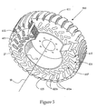
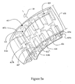
- FIG. 5a there is shown a diagrammatic representation through a portion of the work machine tire 410 of Figure 5 .
- the unpressurized cavities 415 are illustrated as extending about half the width 431 of the tire 410.
- the first radial band of cavities 416 includes an inboard band of cavities 416a and an outboard band of cavities 416b that are out of phase with respect to the inboard band of cavities 416a about the axis of rotation 18.
- the second radial band of cavities 417 includes an inboard band of cavities 417a and an outboard band of cavities 417b that are out of phase with respect to the inboard band of cavities 417a about the axis of rotation 18.
- the cavities 415 are evenly spread throughout the radial middle region 412 of the tire 410 in order to provide uniform performance of the tire 410 throughout 360° of rotation.
- each cavity of the plurality 415 includes a tapered end 426 adjacent to the middle of the width 431 of the tire 410.
- the tapered ends 426 of the cavities 415 eases the removal of a molding core from the elastomeric material to form the cavities 415 during manufacturing.
- a taper can impart a different spring rate to the tire, and can be used to tailor the ground pressure distribution under the tire, i.e. cause the middle of the tire to carry more load.
- tire 510 includes a radial inner region 14, a radial middle region 512 that includes a plurality of unpressurized cavities 415 and a radial outer region 513 that includes the tread.
- the tread has a depth 522 of about 1.37 inches.
- This embodiment is similar to some of the previous embodiments in that each of the radial bands of cavities 516 and 517 each include twenty cavities. Also, this embodiment differs from the earlier embodiment in that the ratio of the material volume to the combined void volume in the middle region 412 is 1.6, which is still about twice.
- Table I there is shown data summarizing the geometry for the six embodiments of the work machine tire 10,110, 210, 310, 410 and 510.
- Each work machine tire 10, 110, 210, 310, 410 and 510 are 31 inch diameter tires made for a skid steer loader.
- Table I EMBOD. TREAD DEPTH in. STIFFNESS @4500#, lb/in CAVITY WIDTH in. CAVITY LENGTH in.
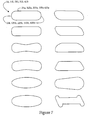
- FIG. 7 there is shown a collection of diagrammatic representations of various-shaped cavities of work machine tires, according to the present disclosure.
- the work machine tires 10, 110, 210, 310, 410 and 510 of the illustrated embodiments include pluralities of cavities 15, 115, 215, 315, 415 and 515 that include the preferred cross-sectional shape having the pair of straight deflectable wall portions 25a, 125a, 225a, 325a, 425a separated by the pair of symmetrical arches 25b, 125b, 225b, 325, 425b.
- the present disclosure contemplates use of various other cavity shapes, all of which include a pair of deflectable wall portions separated by a pair of arches, including, but not limited to, those illustrated in Figure 7 .
- the shapes are preferably symmetrical, but can have a skewed shape. Further, the present disclosure contemplates a work machine tire including non-uniform cavities. Those skilled in the art appreciate that there are various combinations of cavity shapes that can provide the desired stiffness, torque cancellation, and durability of the work machine tire. Thus, Fig. 7 represents only a fraction of cavity shapes that are appropriate for the work machine tire.
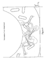
- FIG. 8 there is shown a diagrammatic representation illustrating the deflection of a work machine under a radial load.
- the dotted and dashed lines show contours of constant strain in the elastomeric material out of which the tire is manufactured.
- strain appears to the largest in small regions adjacent the arches of the respective cavities.
- the material surrounding the cavities absorbs the radial load primarily by bending the deflectable wall portions of each cavity toward one another while the arches at the opposite ends of each cavity deform to accommodate the deflection of the wall portions.
- the tire deflects while minimizing material strain.
- the work machine tire can include a progressive spring, or deflection, rate, meaning that stiffness is greater at higher radial loads than at lower radial loads. This assists the tire in supporting a load without collapsing the cavities at relatively high radial loads.
- the cavities can collapse such that the wall portions contact one another, and the radial load will be absorbed through the rubber-to-rubber contact in order to place an upper limit on the maximum strain for a given tire strain.
- the overload protection collapse of the cavities 15 occurs at approximately 6,000 pounds.
- the cavities do not collapse over an expected load range for the particular tire, work machine and application.
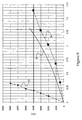
- FIG. 9 there is shown a graph illustrating deflection (D) of a work machine tire versus radial load (L), according to the present disclosure.
- Deflection (D) is illustrated along the x-axis in inches
- the radial load (L) is illustrated along the y-axis in pounds.
- the upward concavity of the curve demonstrates a preferred progressive spring rate.
- the work machine tire 10 preferably includes an average deflection rate 28 in this skid steer example of about 0.3 inches per 1000 pounds, at least up to a load of 4000 pounds.
- a deflection rate 29 of a conventional solid, non-pneumatic tire is about .05 inches per 1000 pounds.
- the deflection rate 30 of a conventional pneumatic tire is greater than the deflection rate 28 for the work machine tire
- the deflection rate 28 for the work machine tire 10 is more similar to the deflection rate 30 for the pneumatic tire than the deflection rate 29 of the solid tire.
- the material volume is more than one and a half times greater than the combined void volume, and the first radial band of cavities 16, 116, 216, 316, 416 and 516 is oriented at a positive angle with respect to a radius therethrough and the second radial band of cavities 17, 117, 217, 317, 417 and 517 is oriented at a negative angle with respect to a radius therethrough.
- the work machine tire 10 During normal operation of the skid steer loader, the work machine tire 10 will be subjected to a predictable range of radial loads. Under this range of radial loads, the material around the plurality of cavities 15 absorbs the radial load primarily by bending rather than by pure compression or stretching, thereby maintaining a relatively low maximum strain on the material. The deflection of the work machine tire 10 by bending the material that defines cavities 15 will cause a larger contact area with the ground, which provides increased traction. Due to the bending around the cavities 15 during normal operation of the work machine, the work machine tire 10 will have a stiffness more comparable to that of a pneumatic tire than a solid tire, and thus, provide the work machine operator with a relatively smooth ride. As illustrated in Figure 9 , the deflection rate 28 of the work machine 10 under 4000 pounds is more similar to the deflection rate 30 of a conventional pneumatic tire than the deflection rate 29 of a conventional solid tire.
- the work machine tire 10 preferably includes the deflection rate of 0.3 inches per 1000 pounds up to 4000 pounds, the work machine tire 10 includes a progressive spring rate that provides protection for the work machine tire 10 and the skid steer loader.
- the work machine tire 10 may become stiffer at higher radial loads.
- the cavities 15 can remain open under the higher radial loads.
- the cavities 15 will collapse, and the rubber-to-rubber contact will absorb the overload. The collapse will limit the strain that can be placed on the material.
- each radial band of cavities 16 and 17 will have a torsional stiffness bias in the direction of their respective angles, the second radial band of cavities 17 at the negative angle can cancel the torsional stiffness bias of the first radial band of cavities 16 at the positive angle, and vice versa.
- the torque will not move an outer portion of the tire 10 in relation to an inner portion of the tire 10 different amounts depending on whether the tangential force from the torque is in a forward direction or a reverse direction.
- the opposing angles of the cavities 15 provide a balanced clockwise and counterclockwise torsional stiffness for the work machine tire.
- the material volume to combined void volume can be altered.
- other considerations were made, including an assessment of how similar the ride would be to a pneumatic tire, whether there was adequate lateral stability (i.e. no worse than a pneumatic tire), and whether the flotation and traction approximated a pneumatic tire.
- Other considerations included maximizing torsional stiffness, minimizing elastomer strain and finally, maximizing the radial load at which the cavities would collapse.
- all work machine tires contemplated by the present disclosure have a material volume to void volume ratio more than one and a half, in the preferred embodiment for the work machine tire 10 for a skid steer loader, the material volume is about twice the combined void volume.
- the material volume to combined void volume can be altered by altering the size, angle and number of the cavities 15.
- the work machine tires 10, 110, 210 of the first, second and third embodiments have different material volume to combined void volume, ratios because the size, rather than the number, of the cavities 15, 115, 215 differs among the work machine tires 10, 110 and 210.
- a relatively low stiffness is desirable, the decrease in stiffness and strain is limited by the normal operating radial loads and the desired tread depth. The greater the normal operating load, the greater material volume to combined void volume may be required. The decrease in stiffness is also limited by the desired depth of the tread.
- the depth 22 of the tread 21 is 1.74 inches. Overall, it is generally a goal to maximize tread depth while maintaining a relatively low stiffness and material strain.
- the present disclosure contemplates various methods for limiting the torsional stiffness bias through the opposing radial bands of cavities.
- the radial bands of cavities 16 and 17 are at different opposing angles, 63° positive angle and 52° negative angle with respect to a radial line through the center of the cavity, but each cavity within the plurality 15 has a uniform shape and size, which may include a taper.
- Each cavity 15 has straight segments or deflectable wall portions 15a separated by curved segments or arches 15b that have a width of approximately 0.9 inch.
- the total cavity length is about 2.3 inches.
- the present disclosure contemplates the torsional stiffness bias being cancelled by altering the angles, size, number and shape of the cavities 15.
- the torsional stiffness bias could also be cancelled by radial bands having the same positive and negative angles, but different sizes and/or shapes.
- radial bands having the same positive and negative angles, but different sizes and/or shapes.
- Reducing torsional stiffness bias can prevent or reduce uncontrolled forward/reverse motion of the work machine during a change of a vertical load.
- this same factor can serve to prevent or reduce uncontrolled vertical motion from a forward or reverse torque.
- the present disclosure is advantageous because it provides a durable work machine tire that provides a relatively smooth ride for a work machine operator, the work machine and the load. Because the material volume of the radial middle region 12 is, at least, one and a half times greater than the combined void volume of the plurality of cavities 15, the work machine tire can provide the durability required of a work machine tire in harsh environments and under relatively substantial loads. However, because the work machine tire 10 defines the plurality of cavities 15, the rubber can mostly bend, rather than purely compress or stretch, under the loads. Thus, the work machine tire 10 can also provide more deflection, creating a softer ride, at lower rubber strains.
- the radial bands of cavities 16 and 17 being oriented at positive and negative angles relative to a respective radius therethrough can cancel the torsional stiffness bias of one another.
- the material surrounding the cavities 15 can absorb the tangential forces acting on the tire 10 while limiting the rotation of the outer portion of the tire relative to the inner portion during periods of acceleration, deceleration, and torques due to normal work cycles.
- the present disclosure is also advantageous because the work machine tire 10 and work machine is protected from overload. Because the work machine tire 10 include the progressive deflection rate, the increased stiffness at higher radial loads allows the cavities 15 to remain open at the higher radial loads. However, when the tire is subjected to an overload situation, the work machine tire 10 will limit the material strain by collapsing the cavities 15. The rubber-to-rubber contact can absorb the overload but the tire then performs more like a solid tire.
- the present disclosure is advantageous because the dimensions of the radial middle region can be adjusted to fit the desired operating goals of each specific work machine tire.
- the compromise between tread depth and strain and stiffness can be adjusted by adjusting the material volume to combined void volume ratio.
- the angles, size, number and shapes of the cavities can be adjusted in order to sufficiently cancel the torsional stiffness bias of the radial band of cavities and produce other known performance characteristics.
Landscapes
- Engineering & Computer Science (AREA)
- Mechanical Engineering (AREA)
- Tires In General (AREA)
- Springs (AREA)
Claims (10)
- Arbeitsmaschinenreifen (10, 110, 210, 310, 410, 510), der Folgendes aufweist:einen ringförmigen Körper (11, 111, 211, 311, 411) aus Elastomermaterial, der einen radialen mittleren Bereich (12, 112, 212, 312, 412, 512) mit einem Materialvolumen aufweist und eine Vielzahl von nicht unter Druck stehenden Hohlräumen mit einem kombinierten Leervolumen definiert, die in einem Muster verteilt sind, welches ein erstes radial inneres Band von Hohlräumen (16, 116, 216, 316, 416, 516) und ein zweites radial äußeres Band von Hohlräumen (17, 117, 217, 317, 417, 517) aufweist;wobei jeder Hohlraum des ersten radialen Bandes von Hohlräumen (16, 116, 216, 316, 416, 516) in einem positiven Winkel bezüglich eines Radius dort hindurch orientiert ist;wobei jeder Hohlraum des zweiten radialen Bandes von Hohlräumen (17, 117, 217, 317, 417, 517) in einem negativen Winkel bezüglich eines Radius dort hindurch orientiert ist, dadurch gekennzeichnet, dass das Materialvolumen mehr als eineinhalb mal größer ist als das kombinierte Leerstellenvolumen.
- Arbeitsmaschinenreifen (10, 110, 210, 310, 410, 510) nach Anspruch 1, der eine durchschnittliche Verformungsrate besitzt, die ungefähr 0,3 Inch (7,62 mm) pro 1000 Pfund (4450 N) bis zu mindestens einer Last von 4000 Pfund (17800 N) ist.
- Arbeitsmaschinenreifen (10, 110, 210, 310, 410, 510) nach Anspruch 1, wobei die nicht unter Druck stehenden Hohlräume jeweils eine Symmetrieachse haben, die parallel zu einer Reifendrehachse (18) ist;
wobei die nicht unter Druck stehenden Hohlräume eine gleichmäßige Form und ein gleichmäßiges Volumen haben; und
wobei jedes der radialen Bänder zwanzig Hohlräume hat. - Arbeitsmaschinenreifen (10, 110, 210, 310, 410, 510) nach Anspruch 1, wobei die nicht unter Druck stehenden Hohlräume jeweils eine Querschnittsform mit einem Umfang (25) haben, der ein Paar von geraden Segmenten (25a, 125a, 225a, 325a, 425a) aufweist, die durch ein Paar von gekrümmten Segmenten (25b, 125b, 225b, 325b, 425b) getrennt werden.
- Arbeitsmaschinenreifen (10, 110, 210, 310, 410, 510) nach Anspruch 1, der mindestens eine Barriere (27) aufweist, die die nicht unter Druck stehenden Hohlräume von dem Raum trennt, der den Reifen umgibt.
- Arbeitsmaschinenreifen (10, 110, 210, 310, 410, 510) nach Anspruch 1, wobei das erste radiale Band von Hohlräumen (16, 116, 216, 316, 416, 516) ein weiter innen liegendes Band von Hohlräumen und ein weiter außen liegendes Band von Hohlräumen aufweist, die radial außer Phase bezüglich des weiter innen liegenden Bandes von Hohlräumen um eine Reifendrehachse (18) sind.
- Arbeitsmaschinenreifen (10, 110, 210, 310, 410, 510) nach Anspruch 1, wobei das Materialvolumen ungefähr zweimal das kombinierte Leervolumen ist.
- Arbeitsmaschinenreifen (10, 110, 210, 310, 410, 510) nach Anspruch 1, wobei der ringförmige Körper (11, 111, 211, 311, 411) einen hohlraumfreien radialen äußeren Bereich benachbart zum mittleren Bereich aufweist, der ein freiliegendes Geländeprofilmuster aufweist; und
wobei das Geländeprofilmuster eine Profiltiefe hat, die mindestens ein Inch (25,4 mm) ist. - Arbeitsmaschinenreifen (10, 110, 210, 310, 410, 510) nach Anspruch 1, wobei jeder der Vielzahl von Hohlräumen durch erste und zweite Bögen definiert ist, die durch erste und zweite auslenkbare Wandteile verbunden sind.
- Arbeitsmaschinenreifen (10, 110, 210, 310, 410, 510) nach Anspruch 1, wobei die Vielzahl von Hohlräumen derart bemessen und angeordnet ist, dass eine radiale Last bewirkt, dass die ersten und zweiten Wandteile sich zueinander hin in einem Bereich benachbart zu radialen Last auslenken.
Applications Claiming Priority (2)
| Application Number | Priority Date | Filing Date | Title |
|---|---|---|---|
| US10/864,898 US7174936B2 (en) | 2003-12-22 | 2004-06-09 | Solid suspended work machine tire |
| PCT/US2005/012146 WO2006001875A1 (en) | 2004-06-09 | 2005-04-11 | Solid work machine tire with resilient body |
Publications (2)
| Publication Number | Publication Date |
|---|---|
| EP1753629A1 EP1753629A1 (de) | 2007-02-21 |
| EP1753629B1 true EP1753629B1 (de) | 2011-01-05 |
Family
ID=34965675
Family Applications (1)
| Application Number | Title | Priority Date | Filing Date |
|---|---|---|---|
| EP05735517A Expired - Lifetime EP1753629B1 (de) | 2004-06-09 | 2005-04-11 | Arbeitsmaschinen-vollreifen mit elastischem körper |
Country Status (8)
| Country | Link |
|---|---|
| US (1) | US7174936B2 (de) |
| EP (1) | EP1753629B1 (de) |
| CN (1) | CN100564074C (de) |
| AT (1) | ATE494160T1 (de) |
| AU (1) | AU2005257777A1 (de) |
| CA (1) | CA2565434C (de) |
| DE (1) | DE602005025758D1 (de) |
| WO (1) | WO2006001875A1 (de) |
Families Citing this family (81)
| Publication number | Priority date | Publication date | Assignee | Title |
|---|---|---|---|---|
| US20070029020A1 (en) * | 2004-06-09 | 2007-02-08 | Caterpillar Inc. | Solid suspended tire |
| GB2448026B (en) * | 2005-02-09 | 2008-11-26 | Remotec Uk Ltd | Tyre |
| JP4950563B2 (ja) * | 2005-06-07 | 2012-06-13 | インベンテイオ・アクテイエンゲゼルシヤフト | 柔軟なハンドレールを駆動するホイール |
| US20070119531A1 (en) * | 2005-11-25 | 2007-05-31 | Amerityre | Airless spare tire |
| US7743711B2 (en) * | 2006-03-08 | 2010-06-29 | Leitner-Poma Of America, Inc. | Deformable drive sheave |
| WO2008009042A1 (en) * | 2006-07-18 | 2008-01-24 | Crocodile Technology (Uk) Limited | Tyre construction |
| AP2009004883A0 (en) * | 2006-11-03 | 2009-06-30 | Bpt Technologies Propritary Ltd | A wheel |
| EP2091760B1 (de) * | 2006-11-24 | 2012-08-15 | Alliance Tire Co. | Reifen für landwirtschaftliches fahrzeug |
| US11014407B2 (en) | 2007-03-27 | 2021-05-25 | Bridgestone Americas Tire Operations, Llc | Tension-based non-pneumatic tire |
| US8109308B2 (en) | 2007-03-27 | 2012-02-07 | Resilient Technologies LLC. | Tension-based non-pneumatic tire |
| US8104524B2 (en) | 2007-03-27 | 2012-01-31 | Resilient Technologies Llc | Tension-based non-pneumatic tire |
| CN101687432B (zh) * | 2007-06-29 | 2012-01-25 | 米其林研究和技术股份有限公司 | 具有圆柱形元件的弹性剪切带及包括该剪切带的车轮 |
| US8056593B2 (en) * | 2007-10-26 | 2011-11-15 | Chemtura Corporation | Non-pneumatic tire |
| US8061398B2 (en) * | 2008-02-25 | 2011-11-22 | Chemtura Corporation | Non-pneumatic tire having angled tread groove wall |
| US20090110894A1 (en) * | 2007-10-26 | 2009-04-30 | Nybakken George H | Polyurethane elastomer articles from low free diphenylmethane diisocyanate prepolymers |
| USD602422S1 (en) | 2007-12-10 | 2009-10-20 | Chemtura Corporation | Tire |
| USD602852S1 (en) | 2007-10-26 | 2009-10-27 | Chemtura Corporation | Tire |
| US9139046B2 (en) * | 2007-11-13 | 2015-09-22 | Caterpillar, Inc. | Adjustable insert for a tire |
| US20090121542A1 (en) * | 2007-11-13 | 2009-05-14 | Caterpillar Inc. | Track for a machine |
| US20090211677A1 (en) * | 2008-02-25 | 2009-08-27 | Palinkas Richard L | Modular tire assembly |
| US20090211681A1 (en) * | 2008-02-25 | 2009-08-27 | Palinkas Richard L | Tire and tire rim assembly |
| NL1035290C2 (nl) * | 2008-04-14 | 2009-10-15 | Magna Tyres Europ B V | Band voor zware voertuigen en matrijs voor het maken van de band. |
| US9108470B2 (en) | 2008-09-29 | 2015-08-18 | Polaris Industries Inc. | Run-flat device |
| US9139045B2 (en) * | 2008-11-06 | 2015-09-22 | Chemtura Corporation | Multiple hardness non-pneumatic tire |
| US20100212797A1 (en) * | 2009-02-24 | 2010-08-26 | Vanquish Products Llc | Adjustable Foam Inserts for Vehicle Tires |
| USD615920S1 (en) | 2009-06-02 | 2010-05-18 | Maine Industrial Tire Llc | Tire |
| US8944125B2 (en) * | 2009-07-20 | 2015-02-03 | Polaris Industries Inc. | Tension-based non-pneumatic tire |
| US8176957B2 (en) * | 2009-07-20 | 2012-05-15 | Resilient Technologies, Llc. | Tension-based non-pneumatic tire |
| US9662939B2 (en) * | 2009-07-28 | 2017-05-30 | Bridgestone Americas Tire Operations, Llc | Tension-based non-pneumatic tire |
| US8479789B2 (en) * | 2009-09-15 | 2013-07-09 | Giles A. Hill, III | Self-pumping vent holes for cooling solid rubber tire and method of construction |
| US8555941B2 (en) * | 2010-08-12 | 2013-10-15 | The Boeing Company | Non-pneumatic survivable tire, cover and fabrication processes |
| US20120234444A1 (en) | 2011-03-18 | 2012-09-20 | Chemtura Corporation | Non-pneumatic tire with annular spoke reinforcing web |
| BR112014029278B1 (pt) * | 2011-05-24 | 2020-09-01 | Prospect Sa Investments 121 Limited | Pneu sem ar para veículos |
| US8905097B2 (en) | 2012-02-01 | 2014-12-09 | Bridgestone Americas Tire Operations, Llc | Agricultural tire tread |
| US9573422B2 (en) | 2012-03-15 | 2017-02-21 | Polaris Industries Inc. | Non-pneumatic tire |
| US20140062171A1 (en) * | 2012-08-30 | 2014-03-06 | Caterpillar Inc. | Non-pneumatic tire |
| US20140062168A1 (en) * | 2012-08-30 | 2014-03-06 | Caterpillar Inc. | Non-pneumatic tire |
| US20140062169A1 (en) * | 2012-08-30 | 2014-03-06 | Caterpillar Inc. | Non-pneumatic tire |
| US20140062170A1 (en) * | 2012-08-30 | 2014-03-06 | Caterpillar Inc. | Non-pneumatic tire |
| US20140062172A1 (en) * | 2012-08-30 | 2014-03-06 | Caterpillar Inc. | Non-pneumatic tire |
| US9149994B2 (en) | 2012-12-12 | 2015-10-06 | Caterpillar Inc. | Systems for molding non-pneumatic tires |
| JP6051037B2 (ja) * | 2012-12-26 | 2016-12-21 | 株式会社ブリヂストン | 非空気入りタイヤ |
| JP6242015B2 (ja) * | 2012-12-26 | 2017-12-06 | 株式会社ブリヂストン | 非空気入りタイヤ |
| US9242509B2 (en) * | 2013-02-07 | 2016-01-26 | Alice Chang | Non pneumatic vehicle tires and pneumatic vehicle tires with tread patterns |
| KR101356326B1 (ko) * | 2013-02-28 | 2014-01-29 | 한국타이어 주식회사 | 각선재 구조의 구조 보강물을 가지는 비공기입 타이어 |
| USD727247S1 (en) | 2013-03-15 | 2015-04-21 | Caterpillar Inc. | Non-pneumatic tire |
| USD731962S1 (en) | 2013-03-15 | 2015-06-16 | Caterpillar Inc. | Surface pattern for a tire |
| US20150034225A1 (en) * | 2013-07-30 | 2015-02-05 | Caterpillar Inc. | Reinforced non-pneumatic tire and system for molding reinforced non-pneumatic tire |
| CN103434343A (zh) * | 2013-09-02 | 2013-12-11 | 昆山建金工业设计有限公司 | 一种防爆轮胎 |
| WO2015047780A1 (en) | 2013-09-24 | 2015-04-02 | Bridgestone Americas Tire Operations, Llc | Tire with toroidal element |
| EP3086948B1 (de) | 2013-12-24 | 2020-03-11 | Bridgestone Americas Tire Operations, LLC | Luftloser reifenaufbau mit veränderlicher steifheit |
| US9919874B2 (en) * | 2014-03-10 | 2018-03-20 | Goodrich Corporation | Compliant tire |
| USD746220S1 (en) * | 2014-04-13 | 2015-12-29 | Bridgestone Americas Tire Operations, Llc | Tire tread |
| USD744408S1 (en) * | 2014-05-20 | 2015-12-01 | Cheng Shin Rubber (Xiamen) Ind, Ltd. | Tire |
| US9487046B2 (en) | 2014-07-18 | 2016-11-08 | Caterpillar Inc. | Laminated non-pneumatic tire |
| USD776604S1 (en) * | 2014-11-24 | 2017-01-17 | Compagnie Generale Des Etablissements Michelin | Wheel tread |
| USD777655S1 (en) | 2014-12-02 | 2017-01-31 | Caterpillar Inc. | Urethane tire |
| USD813152S1 (en) | 2014-12-18 | 2018-03-20 | Bridgestone Americas Tire Operations, Llc | Non-pneumatic tire |
| USD812552S1 (en) | 2014-12-18 | 2018-03-13 | Bridgestone Americas Tire Operations, Llc | Non-pneumatic tire |
| USD813151S1 (en) | 2014-12-18 | 2018-03-20 | Bridgestone Americas Tire Operations, Llc | Non-pneumatic tire |
| WO2016100017A1 (en) | 2014-12-18 | 2016-06-23 | Bridgestone Americas Tire Operations, Llc | Tire with arched spokes |
| USD792332S1 (en) | 2015-06-03 | 2017-07-18 | Mtd Products Inc | Non-pneumatic tire |
| US10899169B2 (en) | 2015-01-27 | 2021-01-26 | Mtd Products Inc | Wheel assemblies with non-pneumatic tires |
| US20160214435A1 (en) | 2015-01-27 | 2016-07-28 | Mtd Products Inc | Wheel assemblies with non-pneumatic tires |
| USD767483S1 (en) | 2015-02-13 | 2016-09-27 | Caterpillar Inc. | Tire tread |
| USD784917S1 (en) | 2015-06-03 | 2017-04-25 | Mtd Products Inc | Non-pneumatic tire |
| USD773387S1 (en) | 2015-07-10 | 2016-12-06 | Caterpillar Inc. | Tire shear band |
| USD803147S1 (en) * | 2015-08-07 | 2017-11-21 | Maxam Tire North America Inc. | Tire |
| US11407254B2 (en) * | 2015-12-11 | 2022-08-09 | Compagnie Generale Des Etablissements Michelin | Non-pneumatic tyre with an improved cavity aperture |
| KR101789407B1 (ko) * | 2016-02-26 | 2017-10-23 | 엘지전자 주식회사 | 로봇 청소기 및 바퀴 어셈블리 |
| CA175976S (en) * | 2017-01-24 | 2018-08-21 | Michelin & Cie | Tire |
| WO2018204250A1 (en) * | 2017-05-01 | 2018-11-08 | Achaemenid, Llc | Electric shock guard for appliance |
| PL423490A1 (pl) * | 2017-11-17 | 2019-05-20 | Korzekwa Anita Przed Produkcyjno Handlowe Anitex | Opona koła wózka dziecięcego |
| RU2758560C1 (ru) * | 2018-03-23 | 2021-10-29 | Треллеборг Вил Системз Италия С.П.А. | Сплошная шина с особыми амортизирующими отверстиями, разработанная для применения в промышленности и строительстве |
| USD913910S1 (en) * | 2018-04-06 | 2021-03-23 | Fredrick Taylor | Tire tread |
| USD859296S1 (en) | 2018-04-19 | 2019-09-10 | Compagnie Generale Des Etablissements Michelin | Tire |
| USD909286S1 (en) * | 2019-07-25 | 2021-02-02 | Vision Technical Services Pty Ltd | Airless sand tire |
| US12145404B2 (en) * | 2019-08-09 | 2024-11-19 | Berkshire Grey Operating Company, Inc. | Systems and methods for providing wheels having variable spring rates |
| US11148468B1 (en) | 2021-05-03 | 2021-10-19 | Abraham Ballena | Non-pneumatic tire with individual tire modules |
| USD1017526S1 (en) * | 2021-09-10 | 2024-03-12 | Otr Wheel Engineering, Inc. | Tire tread |
| USD1037990S1 (en) * | 2022-12-21 | 2024-08-06 | Sailun Group Co., Ltd. | Tire |
Family Cites Families (89)
| Publication number | Priority date | Publication date | Assignee | Title |
|---|---|---|---|---|
| US401896A (en) * | 1889-04-23 | mcfarlane | ||
| US410603A (en) * | 1889-09-10 | Cash indicator and register | ||
| US329413A (en) * | 1885-10-27 | Brush | ||
| US455996A (en) * | 1891-07-14 | Boom-stick | ||
| US1402190A (en) | 1922-01-03 | Cushion | ||
| US317584A (en) * | 1885-05-12 | Device for converting motion | ||
| US57136A (en) * | 1866-08-14 | Improved punch | ||
| US414724A (en) * | 1889-11-12 | Inson | ||
| US68536A (en) * | 1867-09-03 | Improvement in hay-knives | ||
| US82002A (en) * | 1868-09-08 | Improvement in horse hay-rakes | ||
| DE123458C (de) | ||||
| US92589A (en) * | 1869-07-13 | Improvement in automatic fan | ||
| US2603267A (en) | 1952-07-15 | Resilient wheel | ||
| US1485573A (en) | 1924-03-04 | swinehart | ||
| US1195379A (en) | 1916-08-22 | Besilient wheel | ||
| US654169A (en) | 1900-03-13 | 1900-07-24 | Paul Humphrey Macneil | Wheel. |
| US965922A (en) | 1908-04-15 | 1910-08-02 | Emile Baptiste Merigoux | Resilient tire. |
| US982634A (en) | 1909-12-21 | 1911-01-24 | Frank Reed | Tire. |
| US1040074A (en) | 1910-11-21 | 1912-10-01 | Michael M Weiss | Cushion-tire for vehicle-wheels. |
| US1026468A (en) | 1911-03-02 | 1912-05-14 | American Tire & Rubber Company | Cushion-tire for vehicle-wheels. |
| US1113912A (en) * | 1913-01-13 | 1914-10-13 | Frederick V Roesel | Core for resilient wheel-tires. |
| US1165512A (en) * | 1915-02-10 | 1915-12-28 | Thomas N Jordan | Tire. |
| US1258573A (en) | 1917-04-06 | 1918-03-05 | Samuel Johnstone | Automobile cushion-wheel. |
| US1386512A (en) | 1919-02-19 | 1921-08-02 | Henry M Lambert | Tire-mold |
| US1402947A (en) | 1919-03-01 | 1922-01-10 | Samuel Johnstone | Tire |
| US1365539A (en) | 1919-12-03 | 1921-01-11 | John J Rowe | Vehicle-tire |
| US1570048A (en) | 1920-08-25 | 1926-01-19 | Faultless Pneumatic Tire Compa | Vehicle tire |
| US1430100A (en) | 1920-10-15 | 1922-09-26 | Lawrence O Mitchell | Tire |
| US1462760A (en) | 1920-12-13 | 1923-07-24 | K F & C Tire & Rubber Corp | Cushion tire |
| US1444892A (en) * | 1921-01-26 | 1923-02-13 | Westgate Harry Grover | Tire filler |
| US1423580A (en) * | 1921-04-27 | 1922-07-25 | Robbins George Arthur Howard | Resilient core for motor tires |
| GB185988A (en) | 1921-11-01 | 1922-09-21 | George Arthur Howard Robbins | Improvements in resilient cores for motor tyres |
| US1414252A (en) | 1921-12-29 | 1922-04-25 | William A Brubaker | Cushion tire |
| US1678014A (en) | 1922-08-04 | 1928-07-24 | Overman Cushion Tire Company I | Tire |
| US1617870A (en) * | 1922-08-29 | 1927-02-15 | Snider Charles Albert | Cushion tire |
| US1624856A (en) | 1922-09-05 | 1927-04-12 | Arthur E Bauman | Resilient tire |
| US1702081A (en) | 1922-11-17 | 1929-02-12 | Schuyler C Hatfield | Hub tire |
| US1469020A (en) * | 1923-03-12 | 1923-09-25 | Clarence S Preston | Resilient channel and cushion tire |
| FR567280A (fr) | 1923-06-11 | 1924-02-27 | Perfectionnement aux bandages élastiques cellulaires | |
| US1670827A (en) | 1923-07-26 | 1928-05-22 | Seiberling Rubber Co | Vehicle tire |
| US1584785A (en) | 1923-09-04 | 1926-05-18 | Charles D Mccollough | Resilient wheel tire |
| US1526503A (en) | 1923-11-05 | 1925-02-17 | Clarence S Preston | Semisolid tire |
| US1641150A (en) | 1924-01-30 | 1927-09-06 | William A Brubaker | Cushion tire |
| US1524718A (en) | 1924-02-16 | 1925-02-03 | John H Leach | Cushion tire |
| US1597381A (en) | 1924-05-13 | 1926-08-24 | Henry M Lambert | Cushion tire |
| US1572440A (en) | 1924-07-03 | 1926-02-09 | Lambert Tire & Rubber Co | Mold for manufacturing tires |
| US1616843A (en) | 1924-07-29 | 1927-02-08 | William A Brubaker | Cushion tire |
| US1591982A (en) | 1925-03-18 | 1926-07-13 | William R Kirkwood | Demountable cushion tire |
| US1618843A (en) | 1925-04-16 | 1927-02-22 | Marx Richard | Loom |
| US1678631A (en) | 1926-07-12 | 1928-07-31 | Barker John | Vehicle tire |
| US1662007A (en) | 1927-03-17 | 1928-03-06 | Kuhlke Machine Company | Cushion tire |
| GB392299A (en) | 1932-02-12 | 1933-05-18 | British Thomson Houston Co Ltd | Improvements in and relating to dynamo electric machines |
| US2620844A (en) | 1950-04-27 | 1952-12-09 | Lord Mfg Co | Cushioned tire |
| US2742941A (en) | 1952-03-10 | 1956-04-24 | Up Right Inc | Rubber tire |
| US3188775A (en) | 1961-09-25 | 1965-06-15 | William J Cosmos | One piece industrial wheel |
| US3219090A (en) | 1963-09-04 | 1965-11-23 | Air Flex Corp | Wheel |
| US3822732A (en) | 1972-10-16 | 1974-07-09 | Air Cushion Vehicles | Resilient vehicle wheel with corrugated tread wall and inwardly-dished corrugated end walls |
| DE2460050A1 (de) | 1974-12-19 | 1976-06-24 | Bayer Ag | Zweiteilige pannensichere reifen |
| US4226273A (en) | 1978-06-30 | 1980-10-07 | The Goodyear Tire & Rubber Company | Nonpneumatic tire and rim assembly |
| US4921029A (en) | 1984-04-16 | 1990-05-01 | The Uniroyal Goodrich Tire Company | Trapezoidal non-pneumatic tire with supporting and cushioning members |
| US4832098A (en) | 1984-04-16 | 1989-05-23 | The Uniroyal Goodrich Tire Company | Non-pneumatic tire with supporting and cushioning members |
| AT394827B (de) * | 1985-10-16 | 1992-06-25 | Uniroyal Goodrich Tire Co | Reifen |
| DE3614260A1 (de) | 1986-04-26 | 1987-10-29 | Schaeffler Waelzlager Kg | Bauteil aus einem spritz- oder giessbaren polymeren werkstoff |
| US4784201A (en) | 1986-05-13 | 1988-11-15 | The Uniroyal Goodrich Tire Company | Non-pneumatic tire with vibration reducing features |
| JP2632574B2 (ja) | 1987-01-29 | 1997-07-23 | アルトラック リミテッド | 車輪及び無限軌道用の接地噛合部 |
| JPH0195905A (ja) | 1987-10-08 | 1989-04-14 | Sumitomo Rubber Ind Ltd | 注型タイヤ |
| USD317584S (en) | 1987-12-10 | 1991-06-18 | The Ohtsu Tire & Rubber Co., Ltd. | Vehicle tire |
| US5139066A (en) | 1987-12-15 | 1992-08-18 | Altrack Limited | Tire construction |
| US4934425A (en) | 1988-03-23 | 1990-06-19 | Uniroyal Chemical Company, Inc. | Non-pneumatic tire |
| US5078454A (en) | 1988-07-19 | 1992-01-07 | Altrack Limited | Wheel or endless track |
| FR2647715B1 (fr) | 1989-06-01 | 1991-08-23 | Michelin & Cie | Roue auxiliaire a jumeler temporairement a une roue de vehicule, dispositif de roulage ainsi obtenu |
| CA2011473C (en) * | 1989-05-22 | 1998-01-06 | Richard L. Palinkas | Trapezoidal non-pneumatic tire with supporting and cushioning members |
| US4945962A (en) | 1989-06-09 | 1990-08-07 | The Uniroyal Goodrich Tire Company | Honeycomb non-pneumatic tire with a single web on one side |
| FR2652310A1 (fr) | 1989-09-28 | 1991-03-29 | Michelin & Cie | Bandage deformable non pneumatique. |
| BR9106458A (pt) | 1990-05-14 | 1993-05-18 | Altrack Ltd | Meios de aderencia ao solo |
| AU109614S (en) | 1990-05-14 | 1990-11-19 | Altrack Ltd | Tyre |
| CA2043082A1 (en) | 1991-02-27 | 1992-08-28 | James Edward Duddey | Non-pneumatic spare tire |
| US5174634A (en) | 1991-06-28 | 1992-12-29 | Motor Wheel Corporation | Non-pneumatic spare wheel and tire |
| US5265659A (en) | 1992-03-18 | 1993-11-30 | Uniroyal Goodrich Licensing Services, Inc. | Non-pneumatic tire with ride-enhancing insert |
| US5223599A (en) | 1992-04-10 | 1993-06-29 | Uniroyal Chemical Company, Inc. | Polyurethane elastomer and non-pneumatic tire fabricated therefrom |
| CN1154582C (zh) * | 1994-08-19 | 2004-06-23 | 福山护谟工业株式会社 | 非充气轮胎 |
| AU128737S (en) | 1995-05-19 | 1996-11-26 | Airboss Tyres Pty Ltd | Tyre |
| JP2000515452A (ja) * | 1995-11-20 | 2000-11-21 | エアボス タイヤズ ピィーティーワイ リミティッド | 回転可能な地面接地構造体 |
| USD401896S (en) | 1996-05-03 | 1998-12-01 | Airboss Tyres Pty Ltd | Tire |
| US6068353A (en) | 1998-07-10 | 2000-05-30 | Agtracks, Inc. | Track apparatus incorporating non-pneumatic wheels |
| USD414724S (en) | 1998-09-29 | 1999-10-05 | Chiang-Li Lu | Wheel |
| US6834696B1 (en) * | 2000-06-29 | 2004-12-28 | Bridgestone/Firestone North American Tire, Llc | Runflat tire with cantilever-like sidewall construction |
| JP4072708B2 (ja) | 2000-12-28 | 2008-04-09 | 福山ゴム工業株式会社 | クッションタイヤ |
| USD455996S1 (en) | 2001-04-17 | 2002-04-23 | Caterpillar Inc. | Tire |
-
2004
- 2004-06-09 US US10/864,898 patent/US7174936B2/en not_active Expired - Fee Related
-
2005
- 2005-04-11 CN CNB2005800181097A patent/CN100564074C/zh not_active Expired - Fee Related
- 2005-04-11 WO PCT/US2005/012146 patent/WO2006001875A1/en not_active Ceased
- 2005-04-11 DE DE602005025758T patent/DE602005025758D1/de not_active Expired - Lifetime
- 2005-04-11 CA CA2565434A patent/CA2565434C/en not_active Expired - Fee Related
- 2005-04-11 AT AT05735517T patent/ATE494160T1/de not_active IP Right Cessation
- 2005-04-11 AU AU2005257777A patent/AU2005257777A1/en not_active Abandoned
- 2005-04-11 EP EP05735517A patent/EP1753629B1/de not_active Expired - Lifetime
Also Published As
| Publication number | Publication date |
|---|---|
| EP1753629A1 (de) | 2007-02-21 |
| US20050133133A1 (en) | 2005-06-23 |
| CA2565434C (en) | 2013-07-23 |
| DE602005025758D1 (de) | 2011-02-17 |
| CN100564074C (zh) | 2009-12-02 |
| ATE494160T1 (de) | 2011-01-15 |
| WO2006001875A1 (en) | 2006-01-05 |
| AU2005257777A1 (en) | 2006-01-05 |
| US7174936B2 (en) | 2007-02-13 |
| CA2565434A1 (en) | 2006-01-05 |
| CN1964857A (zh) | 2007-05-16 |
Similar Documents
| Publication | Publication Date | Title |
|---|---|---|
| EP1753629B1 (de) | Arbeitsmaschinen-vollreifen mit elastischem körper | |
| WO2008045194A1 (en) | Solid work machine tire with resilient body | |
| JP3985871B2 (ja) | 車両用の非空圧式タイヤ | |
| JP6690103B2 (ja) | 非空気入りタイヤ | |
| EP2910388B1 (de) | Vorrichtung für merhlagige scherbandverstärkung | |
| CN101687433B (zh) | 基于拉伸力的非充气轮胎 | |
| US9139046B2 (en) | Adjustable insert for a tire | |
| MX2013010574A (es) | Llanta no neumatica con refuerzo de radio anular. | |
| CN103732422B (zh) | 具有刀槽花纹密度可变的胎面以及圆形胎冠的轮胎 | |
| JP2011183894A (ja) | 非空気圧タイヤ | |
| EP1759886B1 (de) | Radial-luftreifen für zweirädrige fahrzeuge | |
| JPH0445364B2 (de) | ||
| AU2012288421B2 (en) | Tire for surface vehicle | |
| WO2019010432A1 (en) | NON-PNEUMATIC WHEEL | |
| CA2064369C (en) | Industrial solid tires | |
| JP6911255B2 (ja) | 非空気入りタイヤ | |
| KR102437390B1 (ko) | 비공기압 타이어 | |
| EP4081412B1 (de) | Geräuschverbessernde lauffläche | |
| KR100557510B1 (ko) | 타이어 | |
| CN210617753U (zh) | 农业机械用耐磨轮胎 | |
| JPWO1998025774A1 (ja) | タイヤ構造 |
Legal Events
| Date | Code | Title | Description |
|---|---|---|---|
| PUAI | Public reference made under article 153(3) epc to a published international application that has entered the european phase |
Free format text: ORIGINAL CODE: 0009012 |
|
| 17P | Request for examination filed |
Effective date: 20061013 |
|
| AK | Designated contracting states |
Kind code of ref document: A1 Designated state(s): AT BE BG CH CY CZ DE DK EE ES FI FR GB GR HU IE IS IT LI LT LU MC NL PL PT RO SE SI SK TR |
|
| DAX | Request for extension of the european patent (deleted) | ||
| 17Q | First examination report despatched |
Effective date: 20090529 |
|
| GRAP | Despatch of communication of intention to grant a patent |
Free format text: ORIGINAL CODE: EPIDOSNIGR1 |
|
| GRAS | Grant fee paid |
Free format text: ORIGINAL CODE: EPIDOSNIGR3 |
|
| GRAA | (expected) grant |
Free format text: ORIGINAL CODE: 0009210 |
|
| AK | Designated contracting states |
Kind code of ref document: B1 Designated state(s): AT BE BG CH CY CZ DE DK EE ES FI FR GB GR HU IE IS IT LI LT LU MC NL PL PT RO SE SI SK TR |
|
| REG | Reference to a national code |
Ref country code: GB Ref legal event code: FG4D |
|
| REG | Reference to a national code |
Ref country code: CH Ref legal event code: EP |
|
| REG | Reference to a national code |
Ref country code: IE Ref legal event code: FG4D |
|
| REF | Corresponds to: |
Ref document number: 602005025758 Country of ref document: DE Date of ref document: 20110217 Kind code of ref document: P |
|
| REG | Reference to a national code |
Ref country code: DE Ref legal event code: R096 Ref document number: 602005025758 Country of ref document: DE Effective date: 20110217 |
|
| REG | Reference to a national code |
Ref country code: NL Ref legal event code: VDEP Effective date: 20110105 |
|
| PG25 | Lapsed in a contracting state [announced via postgrant information from national office to epo] |
Ref country code: SI Free format text: LAPSE BECAUSE OF FAILURE TO SUBMIT A TRANSLATION OF THE DESCRIPTION OR TO PAY THE FEE WITHIN THE PRESCRIBED TIME-LIMIT Effective date: 20110105 |
|
| LTIE | Lt: invalidation of european patent or patent extension |
Effective date: 20110105 |
|
| PG25 | Lapsed in a contracting state [announced via postgrant information from national office to epo] |
Ref country code: LT Free format text: LAPSE BECAUSE OF FAILURE TO SUBMIT A TRANSLATION OF THE DESCRIPTION OR TO PAY THE FEE WITHIN THE PRESCRIBED TIME-LIMIT Effective date: 20110105 Ref country code: SE Free format text: LAPSE BECAUSE OF FAILURE TO SUBMIT A TRANSLATION OF THE DESCRIPTION OR TO PAY THE FEE WITHIN THE PRESCRIBED TIME-LIMIT Effective date: 20110105 Ref country code: IS Free format text: LAPSE BECAUSE OF FAILURE TO SUBMIT A TRANSLATION OF THE DESCRIPTION OR TO PAY THE FEE WITHIN THE PRESCRIBED TIME-LIMIT Effective date: 20110505 Ref country code: ES Free format text: LAPSE BECAUSE OF FAILURE TO SUBMIT A TRANSLATION OF THE DESCRIPTION OR TO PAY THE FEE WITHIN THE PRESCRIBED TIME-LIMIT Effective date: 20110416 Ref country code: PT Free format text: LAPSE BECAUSE OF FAILURE TO SUBMIT A TRANSLATION OF THE DESCRIPTION OR TO PAY THE FEE WITHIN THE PRESCRIBED TIME-LIMIT Effective date: 20110505 Ref country code: GR Free format text: LAPSE BECAUSE OF FAILURE TO SUBMIT A TRANSLATION OF THE DESCRIPTION OR TO PAY THE FEE WITHIN THE PRESCRIBED TIME-LIMIT Effective date: 20110406 |
|
| PG25 | Lapsed in a contracting state [announced via postgrant information from national office to epo] |
Ref country code: FI Free format text: LAPSE BECAUSE OF FAILURE TO SUBMIT A TRANSLATION OF THE DESCRIPTION OR TO PAY THE FEE WITHIN THE PRESCRIBED TIME-LIMIT Effective date: 20110105 Ref country code: PL Free format text: LAPSE BECAUSE OF FAILURE TO SUBMIT A TRANSLATION OF THE DESCRIPTION OR TO PAY THE FEE WITHIN THE PRESCRIBED TIME-LIMIT Effective date: 20110105 Ref country code: BG Free format text: LAPSE BECAUSE OF FAILURE TO SUBMIT A TRANSLATION OF THE DESCRIPTION OR TO PAY THE FEE WITHIN THE PRESCRIBED TIME-LIMIT Effective date: 20110405 Ref country code: AT Free format text: LAPSE BECAUSE OF FAILURE TO SUBMIT A TRANSLATION OF THE DESCRIPTION OR TO PAY THE FEE WITHIN THE PRESCRIBED TIME-LIMIT Effective date: 20110105 Ref country code: CY Free format text: LAPSE BECAUSE OF FAILURE TO SUBMIT A TRANSLATION OF THE DESCRIPTION OR TO PAY THE FEE WITHIN THE PRESCRIBED TIME-LIMIT Effective date: 20110105 Ref country code: BE Free format text: LAPSE BECAUSE OF FAILURE TO SUBMIT A TRANSLATION OF THE DESCRIPTION OR TO PAY THE FEE WITHIN THE PRESCRIBED TIME-LIMIT Effective date: 20110105 Ref country code: NL Free format text: LAPSE BECAUSE OF FAILURE TO SUBMIT A TRANSLATION OF THE DESCRIPTION OR TO PAY THE FEE WITHIN THE PRESCRIBED TIME-LIMIT Effective date: 20110105 |
|
| PG25 | Lapsed in a contracting state [announced via postgrant information from national office to epo] |
Ref country code: DK Free format text: LAPSE BECAUSE OF FAILURE TO SUBMIT A TRANSLATION OF THE DESCRIPTION OR TO PAY THE FEE WITHIN THE PRESCRIBED TIME-LIMIT Effective date: 20110105 Ref country code: EE Free format text: LAPSE BECAUSE OF FAILURE TO SUBMIT A TRANSLATION OF THE DESCRIPTION OR TO PAY THE FEE WITHIN THE PRESCRIBED TIME-LIMIT Effective date: 20110105 |
|
| PLBE | No opposition filed within time limit |
Free format text: ORIGINAL CODE: 0009261 |
|
| STAA | Information on the status of an ep patent application or granted ep patent |
Free format text: STATUS: NO OPPOSITION FILED WITHIN TIME LIMIT |
|
| PG25 | Lapsed in a contracting state [announced via postgrant information from national office to epo] |
Ref country code: SK Free format text: LAPSE BECAUSE OF FAILURE TO SUBMIT A TRANSLATION OF THE DESCRIPTION OR TO PAY THE FEE WITHIN THE PRESCRIBED TIME-LIMIT Effective date: 20110105 Ref country code: MC Free format text: LAPSE BECAUSE OF NON-PAYMENT OF DUE FEES Effective date: 20110430 Ref country code: CZ Free format text: LAPSE BECAUSE OF FAILURE TO SUBMIT A TRANSLATION OF THE DESCRIPTION OR TO PAY THE FEE WITHIN THE PRESCRIBED TIME-LIMIT Effective date: 20110105 Ref country code: RO Free format text: LAPSE BECAUSE OF FAILURE TO SUBMIT A TRANSLATION OF THE DESCRIPTION OR TO PAY THE FEE WITHIN THE PRESCRIBED TIME-LIMIT Effective date: 20110105 |
|
| REG | Reference to a national code |
Ref country code: CH Ref legal event code: PL |
|
| 26N | No opposition filed |
Effective date: 20111006 |
|
| PG25 | Lapsed in a contracting state [announced via postgrant information from national office to epo] |
Ref country code: IT Free format text: LAPSE BECAUSE OF FAILURE TO SUBMIT A TRANSLATION OF THE DESCRIPTION OR TO PAY THE FEE WITHIN THE PRESCRIBED TIME-LIMIT Effective date: 20110105 |
|
| PG25 | Lapsed in a contracting state [announced via postgrant information from national office to epo] |
Ref country code: CH Free format text: LAPSE BECAUSE OF NON-PAYMENT OF DUE FEES Effective date: 20110430 Ref country code: LI Free format text: LAPSE BECAUSE OF NON-PAYMENT OF DUE FEES Effective date: 20110430 |
|
| REG | Reference to a national code |
Ref country code: IE Ref legal event code: MM4A |
|
| REG | Reference to a national code |
Ref country code: DE Ref legal event code: R097 Ref document number: 602005025758 Country of ref document: DE Effective date: 20111006 |
|
| PG25 | Lapsed in a contracting state [announced via postgrant information from national office to epo] |
Ref country code: IE Free format text: LAPSE BECAUSE OF NON-PAYMENT OF DUE FEES Effective date: 20110411 |
|
| PG25 | Lapsed in a contracting state [announced via postgrant information from national office to epo] |
Ref country code: LU Free format text: LAPSE BECAUSE OF NON-PAYMENT OF DUE FEES Effective date: 20110411 |
|
| PG25 | Lapsed in a contracting state [announced via postgrant information from national office to epo] |
Ref country code: TR Free format text: LAPSE BECAUSE OF FAILURE TO SUBMIT A TRANSLATION OF THE DESCRIPTION OR TO PAY THE FEE WITHIN THE PRESCRIBED TIME-LIMIT Effective date: 20110105 |
|
| PG25 | Lapsed in a contracting state [announced via postgrant information from national office to epo] |
Ref country code: HU Free format text: LAPSE BECAUSE OF FAILURE TO SUBMIT A TRANSLATION OF THE DESCRIPTION OR TO PAY THE FEE WITHIN THE PRESCRIBED TIME-LIMIT Effective date: 20110105 |
|
| REG | Reference to a national code |
Ref country code: FR Ref legal event code: PLFP Year of fee payment: 11 |
|
| PGFP | Annual fee paid to national office [announced via postgrant information from national office to epo] |
Ref country code: GB Payment date: 20150325 Year of fee payment: 11 |
|
| PGFP | Annual fee paid to national office [announced via postgrant information from national office to epo] |
Ref country code: DE Payment date: 20150429 Year of fee payment: 11 |
|
| PGFP | Annual fee paid to national office [announced via postgrant information from national office to epo] |
Ref country code: FR Payment date: 20150325 Year of fee payment: 11 |
|
| REG | Reference to a national code |
Ref country code: DE Ref legal event code: R119 Ref document number: 602005025758 Country of ref document: DE |
|
| GBPC | Gb: european patent ceased through non-payment of renewal fee |
Effective date: 20160411 |
|
| REG | Reference to a national code |
Ref country code: FR Ref legal event code: ST Effective date: 20161230 |
|
| PG25 | Lapsed in a contracting state [announced via postgrant information from national office to epo] |
Ref country code: GB Free format text: LAPSE BECAUSE OF NON-PAYMENT OF DUE FEES Effective date: 20160411 Ref country code: FR Free format text: LAPSE BECAUSE OF NON-PAYMENT OF DUE FEES Effective date: 20160502 Ref country code: DE Free format text: LAPSE BECAUSE OF NON-PAYMENT OF DUE FEES Effective date: 20161101 |