EP1753093A1 - Connecteur de télécommunications - Google Patents
Connecteur de télécommunications Download PDFInfo
- Publication number
- EP1753093A1 EP1753093A1 EP05017638A EP05017638A EP1753093A1 EP 1753093 A1 EP1753093 A1 EP 1753093A1 EP 05017638 A EP05017638 A EP 05017638A EP 05017638 A EP05017638 A EP 05017638A EP 1753093 A1 EP1753093 A1 EP 1753093A1
- Authority
- EP
- European Patent Office
- Prior art keywords
- connector
- capacitor
- contacts
- accordance
- connector contacts
- Prior art date
- Legal status (The legal status is an assumption and is not a legal conclusion. Google has not performed a legal analysis and makes no representation as to the accuracy of the status listed.)
- Granted
Links
Images


Classifications
-
- H—ELECTRICITY
- H01—ELECTRIC ELEMENTS
- H01R—ELECTRICALLY-CONDUCTIVE CONNECTIONS; STRUCTURAL ASSOCIATIONS OF A PLURALITY OF MUTUALLY-INSULATED ELECTRICAL CONNECTING ELEMENTS; COUPLING DEVICES; CURRENT COLLECTORS
- H01R13/00—Details of coupling devices of the kinds covered by groups H01R12/70 or H01R24/00 - H01R33/00
- H01R13/66—Structural association with built-in electrical component
- H01R13/6608—Structural association with built-in electrical component with built-in single component
- H01R13/6625—Structural association with built-in electrical component with built-in single component with capacitive component
-
- H—ELECTRICITY
- H01—ELECTRIC ELEMENTS
- H01R—ELECTRICALLY-CONDUCTIVE CONNECTIONS; STRUCTURAL ASSOCIATIONS OF A PLURALITY OF MUTUALLY-INSULATED ELECTRICAL CONNECTING ELEMENTS; COUPLING DEVICES; CURRENT COLLECTORS
- H01R13/00—Details of coupling devices of the kinds covered by groups H01R12/70 or H01R24/00 - H01R33/00
- H01R13/646—Details of coupling devices of the kinds covered by groups H01R12/70 or H01R24/00 - H01R33/00 specially adapted for high-frequency, e.g. structures providing an impedance match or phase match
- H01R13/6461—Means for preventing cross-talk
- H01R13/6464—Means for preventing cross-talk by adding capacitive elements
-
- H—ELECTRICITY
- H01—ELECTRIC ELEMENTS
- H01R—ELECTRICALLY-CONDUCTIVE CONNECTIONS; STRUCTURAL ASSOCIATIONS OF A PLURALITY OF MUTUALLY-INSULATED ELECTRICAL CONNECTING ELEMENTS; COUPLING DEVICES; CURRENT COLLECTORS
- H01R24/00—Two-part coupling devices, or either of their cooperating parts, characterised by their overall structure
- H01R24/60—Contacts spaced along planar side wall transverse to longitudinal axis of engagement
- H01R24/62—Sliding engagements with one side only, e.g. modular jack coupling devices
- H01R24/64—Sliding engagements with one side only, e.g. modular jack coupling devices for high frequency, e.g. RJ 45
Definitions
- the invention relates to a connector in the field of telecommunications providing capacitive "cross-talk" reduction, a combination of at least two connectors and a method of connecting a first and a second connector.
- connections are established by telecommunications and/or data lines. These connections can be made by wires, for example copper wires.
- Plural wires can be put together at a connector, such as a plug or a socket. By connecting two connectors of this type with each other, plural connections between the wires, which are connected with each of the connectors, are established.
- a type of connection can also be used in networks, such as local area networks, for any connections between devices being part of the network.
- cross-talk describes an effect in which the contacts of a telecommunications module act as small antennae, which transmit an interfering signal to adjacent contacts.
- the interfering signals are transmitted by a pair of wires and, therefore, by a pair of adjacent contacts.
- cross-talk between the contacts of a single pair is not an issue.
- cross-talk between the contacts of adjacent pairs should be reduced as far as possible.
- the contacts in conventional jack connectors may be in close proximity to one another. If these jack connectors are used in high performance communication systems, cross talk between adjacent conductor pairs may occur.
- each capacitor includes a first and a second electrode.
- the terminals of the electrodes make electrical contact with selected contact wires. However, this contact is made at the free ends of the contact wires. Therefore, large positional tolerances can occur, and the reliability of the electrical connection can be unsatisfactory. This also applies to the subject matter of GB 2 329 530 A and EP 1 160 935 A1 .
- US 2004/0092170 A1 is related to a connector for data-transfer applications, in which some contacts have extensions formed on them to define capacitors.
- the extensions require a considerable space.
- the connection between the contacts and the extensions is subject to breakage.
- the invention provides a connector in the field of telecommunications which shows an improved performance with regard to its cross-talk properties, i.e. to reduce cross-talk. Moreover, a combination of two connectors and a method for connecting two connectors are provided.
- the connector described herein has connector contacts which may be contained within a housing.
- Each connector contact has a first end and a second end.
- the first end of a connector contact is adapted to connect to flexible wires of a communication cable.
- the second end of a connector contact and/or a portion adjacent thereto typically is adapted to make direct electrical connection with the contact of a complementary connector, for example a plug.
- the connector contacts can be resilient, and in the fitted state, biased towards the contacts of the complementary connector. In this way, a reliable electrical connection is achieved.
- the connector contacts of the connector have at least one bend.
- the bend can, for example, serve to provide the aforementioned resiliency.
- the bend can assist in keeping the connector compact, because the bend can bring the first contact area, for example on the first end, where wires are attached to the connector contacts, and the second end, where the connector contacts are adapted to make electrical connection with contacts of a complementary connector, close together.
- the length of the connector as a whole may be kept small.
- the bend can, moreover, be used to provide a reliable electrical connection with at least one capacitor.
- a capacitor serves to compensate cross-talk which can occur between pairs of contacts in the connector.
- telecommunications lines are normally arranged in pairs, and cross-talk can occur between adjacent pairs.
- the connector contacts of a first pair are in close proximity to the connector contacts of a second pair so that cross-talk is particularly likely to occur between these pairs of contacts.
- one contact of each pair is connectable with capacitor leads of at least one capacitor. Since a capacitor is normally formed by two parallel plates, the capacitor leads are generally connected with each of the plates.
- the invention also provides a method of connecting a first connector with at least one second connector, where the second connector effects the connection between connector contacts and capacitor leads.
- the invention provides a connector in the field of telecommunications having connector contacts with at least one bend and at least one capacitor with capacitor leads which are connectable to the connector contacts in the vicinity of the bends of the connector contacts.
- the connector contacts may be formed in any suitable manner, for example, they can be made of bent or straight sections of wires with, for example, a substantially circular cross-section. Alternatively, the contacts can be stamped from sheet metal in the form of narrow strips of metal which can be bent at one or more locations. For this purpose, wires can be soldered to the connector contacts. As an alternative, they can be wrapped around the connector contacts. It is also possible to crimp a part of each connector contact around a wire. Moreover, the connector contacts can have IDC (insulation displacement contacts) zones, which are adapted to cut the insulation of a wire and make electrical contact with the metal core.
- IDC insulation displacement contacts
- IDC zones can be provided on one or more printed circuit boards, on which printed conductors are provided, which provide a connection between the IDC zones and the connector contacts.
- the connector contacts are connected, for example soldered, to the printed conductors.
- wires are normally connected with first ends of the connector contacts.
- the capacitor leads of the connector are connectable to the connector contacts. In other words, there is no permanent connection required such as soldering or a similar type of connection. Such connections are, because of mechanical stress, subject to breakage.
- the capacitor leads in a first position, can be disconnected from the connector contacts and connected with the connector contacts in a second position.
- This arrangement can, for example, be adapted for "activation" by a complementary connector.
- a complementary connector can, when fitted to a first connector, act on the connector contacts to deform and/or displace the free ends of the connector contacts so that these free ends at least partially move to a position which brings the bent portions of the connector contacts into contact with the capacitor leads to make the desired electrical connection.
- At least in the state in which a complementary connector is fitted to a first connector at least one capacitor may be connected with the connector contacts and cross-talk can be reduced.
- the capacitor leads can also, however, be permanently connected with the connector contacts (i.e. in case of tolerances of the connector contacts) and the capacitor leads relative to each other so that these are in contact before a second connector, (for example a plug) is inserted.
- the above-described, flexible or disconnectable connection between the capacitor leads and the connector contacts also allows different types of complementary connectors (such as plugs) to be connected with the connector while reliably establishing contact between the connector contacts and the capacitor leads.
- any kind of tolerances at any components of the connector and/or a complementary connector can be compensated and do not affect the electrical contact between the connector contacts and the capacitor leads.
- the described electrical connection between the capacitor leads and the connector contacts is established in the general vicinity of the bends of the connector contacts.
- these electrical connections can be spaced apart from the free ends of the connector contacts.
- the reliability of the electrical connection can be improved because positional tolerances, vibrations or the like of the free ends of the connector contacts do not affect the electrical connection with the connector contacts.
- the positional accuracy of the connector contacts can be ensured relatively easily and reliably in the vicinity of the bends.
- the electrical connection is also not endangered by mechanical stress, which could break a connection formed for example by soldering.
- costly production steps such as those necessary for soldering can be eliminated.
- connection with the capacitor is brought close to the area where connection is made with a complementary connector such as a plug. This improves cross-talk compensation.
- electrical connection with the capacitor which is formed in the vicinity of the bends can at the same time be arranged relatively close to those free ends of the connector contacts, where they are adapted to be connected with contacts of a complementary connector.
- the connectors described herein can include one or more printed circuit boards.
- the connector contacts may, for example, with their aforementioned first end, be inserted into a printed circuit board.
- IDC zones can be provided on the printed circuit board in order to allow the connection of flexible wires with the IDC zones.
- printed conductors can be formed on the printed circuit board in order to connect the IDC zones with the connector contacts.
- the connector can be formed particularly compact when the at least one bend of the connector contacts has an angle of 90° or less. This, in other words, implies that an acute angle is formed on the connector contacts which keeps the connector compact and provides, as experiments have shown, a reliable connection with the capacitor leads.
- the reliability of the electrical connection can also be improved when positional tolerances of the capacitor are limited.
- This can, for example, be achieved by providing the connector with a contact holder having at least one recess, in which the capacitor is placed.
- the capacitor can be positioned on the contact holder or any other component of the connector in any other suitable manner, such as by positioning pins, suitable steps, etc.
- the connector contacts can be secured to the contact holder.
- the above-described recess for accommodating at least one capacitor can be formed in the guides which can serve to position the connector contacts.
- the recess for accommodating the at least one capacitor can also be formed outside the guides.
- the guides can be formed by grooves with webs, shoulders, partitions or walls between the grooves. The webs can be formed with a reduced height, at least along some portions, so that a recess is formed on one or more such webs, in which the capacitor can be accommodated.
- a contact holder When a contact holder is present, it can efficiently be used to additionally position the connector contacts.
- an efficient structure has been found in a contact holder in which the connector contacts are placed at an inner level and the capacitor is positioned at an outer level.
- the reliable positioning of the connector contacts and/or the capacitor leads can be further improved if the contact holder has guides in which at least portions of the connector contacts and/or the capacitor leads are arranged.
- a capacitor of this type may be formed having plates made from sheet metal or a metallic foil positioned on either side of a dielectric material.
- the capacitor may comprise a non-metallic foil which is metalized on both sides. Capacitors with this structure can be manufactured in a cost-efficient manner. Using a non-conductive foil or a film as the dielectric provides less variation in the distance between the plates which results in less deviation in the capacitance between different capacitors.
- the capacitance can be influenced by choosing an appropriate material and/or an appropriate thickness for the dielectric.
- the capacitance of the capacitor can be set to a predetermined value in a reliable manner and with low tolerances by controlling the surface area of the conductive plates.
- at least one of the plates of the capacitor extends beyond the other plate on at least one edge thereof.
- the plates can be combined in a manner in which a first plate extends beyond a second plate at two opposite edges and the second plate extends beyond the first plate at the other two, opposite edges.
- the dimensions of one plate can be larger in one or two directions so that the larger plate extends beyond the smaller plate at one or more edge of the smaller plate.
- the manufacture of the plates of the capacitor it provides advantages if these are produced by stamping.
- This type of manufacturing is, firstly, efficient and, secondly, allows the formation of the plates with a high accuracy.
- the capacitance of the resulting capacitor can efficiently be set to a predetermined value with low tolerances.
- Other methods for producing the plates of the capacitor, such as cutting, are possible.
- stamping the plates of the capacitor allows very low tolerances of the resulting capacitors, for example smaller than 0.1 pF.
- the assembly of the connector described herein can be facilitated when the capacitor is preassembled and fitted to the connector in the preassembled state.
- it provides advantages when the capacitor has at least one recess or an opening which cooperates with at least one projection formed on the connector.
- the projection can, for example, be a pin accommodated in an opening formed in the capacitor when the capacitor is fitted to the connector.
- resiliency of the connector contacts and capacitor leads is not necessarily required in order to provide the desired connections of the connector contacts with the capacitor leads.
- the reliability of this connection can be improved when the connector contacts and/or the capacitor leads are flexible.
- flexibility or resiliency can, moreover, improve the reliability of the electrical connection with the connector contacts of a complementary connector.
- the capacitor leads can have any suitable form. However, it keeps the structure thereof simple when they are formed substantially straight. It provides advantages when the capacitor leads are connectable to the connector contacts at free ends of the capacitor leads. When this connection is formed in the vicinity of bends of the connector contacts, it has proven to be beneficial when the capacitor leads have, for example, at their free ends at least one curved portion.
- the curved portion can, at least in the connected position, be substantially in conformity with the bend formed on the connector contacts so that a relatively large contact zone is provided in which contact is reliably made.
- the novel connector described herein is not limited to any specific number of connector contacts. However, for specific applications it provides advantages when the connector has eight connector contacts arranged in pairs.
- the single capacitor which can be present in such an embodiment, has two capacitor leads which are connectable to a third and a fifth connector contact. In such an arrangement a first and a second connector contact form a first pair, a third and a sixth connector contact form a second pair, a fourth and a fifth connector contact constitute a third pair, and a seventh and an eighth connector contact form a fourth pair. (See EIA/TIA568A)
- the structure of the connector described herein can also be applied to a plug-type connector, it is currently envisaged to form the novel connector as a socket which is adapted to receive a plug.
- connection of at least one capacitor and connector contacts particularly shows when two connectors are connected with each other. Therefore, a combination of at least one connector designed as described herein and a second connector is to be considered subject matter of the present invention.
- the novel connector being currently preferably designed as a socket the second, complementary connector can, for example, be a plug.
- connector contacts 12 of the connector described herein are formed with a bend 14 defining, in the embodiment shown, an acute angle ⁇ between a first portion 38 and a second portion 40 of the connector contact 12.
- the bend 14 is formed curved, rounded or arc-shaped, as shown in Fig. 1.
- the first portion 38 of the connector contact is adapted for connecting wires (not shown) herewith, as will be described in more detail with reference to Fig. 10, and is, in the embodiment shown, somewhat shorter than the second portion 40. However, the first portion 38 can also have approximately the same length or it can be longer than the second portion 40.
- the second portion 40 of the connector contact is adapted to establish electrical connection, preferably direct electrical connection, with contacts of a complementary connector (see Fig.
- the capacitor is shown at 16 and comprises capacitor leads, of which only one lead 18 is shown in Fig. 1.
- the lead 18 is formed substantially straight, somewhat shorter than the first portion 38 of the connector contact, substantially parallel thereto, and has a curved portion 42 at its free end.
- the curved portion conforms, in the embodiment shown, substantially with the bend 14 of the connector contact and covers an angle of approximately 120°. This angle can also be smaller.
- this conformity serves to form a contact zone which, in the embodiment shown, extends for a considerable part of the bend 14 and the curved portion 42.
- this connector acts, in the embodiment shown, to push the second portion 40 of the connector contacts 12 towards the first portions so that these portions are, in the embodiment shown, almost parallel to each other.
- the mentioned portions can also be arranged non-parallel to each other.
- the connector contacts 12 are, in the embodiment shown, resilient, they are, firstly, biased towards contacts 58 of the second connector 36 and reliably make contact with these. A reliable electrical contact is, secondly, established with the capacitor leads 18.
- the capacitor 16 is, in the embodiment shown, constituted by two plates 26, 28 and a dielectric 30 between them. As will be described in more detail below, one of the plates 28 can be larger than the other plate 26. Moreover, the dielectric 30 can be larger than both plates.
- the capacitor 16 comprises a hole or an opening (which is not visible in the drawing, the opening 32 is shown in Figs. 6 to 9), which serves to accommodate a pin 34.
- the pin 34 is, in the embodiment shown, formed on a contact holder described in more detail below and serves to position the capacitor 16 on the contact holder 20.
- the contact holder 20 also includes, in the embodiment shown, a recess 22 for accommodating the capacitor 16.
- further projections in the form of webs 44 are present in order to space the capacitor 16 from a wall 46 of the contact holder.
- one or more webs 44 can be replaced by one or more pillars, pins or similar projections, which act as spacers.
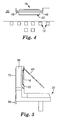
- Fig. 4 shows an alternative arrangement for the recess 22 formed on the contact holder 20.
- steps 48 are provided at the side of the recess 22 in order to locate the capacitor 16.
- the air which is present in the recess 22, serves to space the capacitor from the connector contacts, which are schematically indicated in Fig. 4 at 12. This reduces interference between the connector contacts 12 and the capacitor 16.
- Fig. 5 shows the complete structure of the contact holder 20, on which the connector contacts 12 are arranged.
- the first portions 38 at least these portions as well as the bend 14 (see Fig. 1, the bend 14 is hidden behind a wall in Fig. 5) can be arranged in guides 24 formed on the contact holder 20.
- the guides 24 can be present in form of grooves, which are delimited by webs or walls, one of the walls 50 hiding the bend of the connector contact 12.
- a recess 22 is formed in the contact holder, for example, by reducing the height of webs or walls at least along a portion thereof.
- the contact holder 20 shown in Fig. 5, can be accommodated in a housing (not shown) of the assembled connector.
- the capacitor 16 is constituted by two plates 28, 26, which are arranged in a kind of a "cross".
- the plates 26, 28 are rectangular, and the longer dimensions of each plate are arranged at a substantially right angle to each other.
- the first plate 26 extends beyond the edges of the second plate 28 in the up and down direction according to Fig. 6, and the second plate 28 extends beyond the edges of the first plate 26 in the left and right direction.
- the effective capacitor is defined by that area, where both plates overlap, and is indicated at 52.
- the dielectric 30 is, in the embodiment shown, somewhat'bigger than the plate 28.
- the opening 32 (in the embodiment shown approximately in the center) of the capacitor 16 is shown, which cooperates with the pin 34 (see Fig. 3).
- a first plate 54 is, in two perpendicular directions, smaller than a second plate 56 so that the effective capacitor, i.e., where the plates overlap, is defined by the smaller plate 54 alone because all edges are, in the embodiment shown, substantially parallel.
- the dielectric 30 is larger than both the smaller plate 54 and the larger plate 56. In the case shown, both plates 54 and 56 and the dielectric 30 are substantially square-shaped.
- Fig. 10 shows a sectional view of the novel connector in the form of a socket 60.
- the socket 60 includes a housing which has a first housing part 62 and a second housing part 64.
- the housing parts 62, 64 are connected with each other by mechanical connections, in the embodiment shown by latch hooks 66 provided on the second housing part 64, which cooperate with suitable shoulders 68 of the first housing part 62.
- the second housing part 64 includes a flap 70 which can be opened to provide access to the cavity 72 of the socket 60, which is adapted to receive a plug (not shown).
- a coil spring 74 with two arms is provided to bias the flap 70 to the closed position.
- the connector contacts 12 are exposed to the cavity 72.
- the contact holder 20 which has been described in more detail above with reference to Fig. 5, is shown incorporated into the second housing part 64. As compared to the orientation of Fig. 5, the contact holder is apparent in a mirror image and turned 90°.
- the socket 60 includes a printed circuit board 76, which includes holes, into which the end of the first portion 38 of the connector contacts 12 is inserted. This end is, for example, pressed into or soldered to the printed circuit board 36, and printed conductors (not shown) are provided in order to make connection with the IDC contacts 78. Ends 80 of the IDC contacts are also inserted into openings of the printed circuit board and, for example, pressed into or soldered to printed conductors. Flexible wires (not shown) can be connected with the IDC contacts 78. Finally, in the embodiment shown, a carrier 82 is provided to support the IDC contacts 78. This is particularly beneficial, before the first 62 and second housing part 64 are mated.
- the printed circuit board 76 is provided on the second housing part 64, and the ends 80 of the IDC contacts are inserted into the printed circuit board 76, when the latch hooks 66 of the second housing part 64 engage the shoulders 68 of the first housing part 62.
Landscapes
- Details Of Connecting Devices For Male And Female Coupling (AREA)
Priority Applications (13)
| Application Number | Priority Date | Filing Date | Title |
|---|---|---|---|
| ES05017638T ES2313165T3 (es) | 2005-08-12 | 2005-08-12 | Conectador de telecomunicaciones. |
| PL05017638T PL1753093T3 (pl) | 2005-08-12 | 2005-08-12 | Łącznik telekomunikacyjny |
| AT05017638T ATE405974T1 (de) | 2005-08-12 | 2005-08-12 | Telekommunikatiosverbinder |
| DE602005009179T DE602005009179D1 (de) | 2005-08-12 | 2005-08-12 | Telekommunikatiosverbinder |
| EP05017638A EP1753093B1 (fr) | 2005-08-12 | 2005-08-12 | Connecteur de télécommunications |
| JP2008526135A JP4852606B2 (ja) | 2005-08-12 | 2006-08-08 | 電気通信分野用コネクタ及び少なくとも2個のコネクタの組み合わせ |
| BRPI0614763-1A BRPI0614763A2 (pt) | 2005-08-12 | 2006-08-08 | conector no campo das telecomunicações e combinação de pelo menos dois conectores |
| PCT/US2006/030879 WO2007021684A1 (fr) | 2005-08-12 | 2006-08-08 | Connecteur utilise dans le domaine des telecommunications et combinaison d'au moins deux connecteurs |
| MX2008001924A MX2008001924A (es) | 2005-08-12 | 2006-08-08 | Un conector en el campo de las telecomunicaciones y una combinacion de al menos dos conectores. |
| US11/997,966 US7637780B2 (en) | 2005-08-12 | 2006-08-08 | Connector in the field of telecommunications and a combination of at least two connectors |
| RU2008107933/09A RU2383092C2 (ru) | 2005-08-12 | 2006-08-08 | Соединитель для использования в области телекоммуникаций и соединительное устройство, включающее соединитель |
| ARP060103523A AR054911A1 (es) | 2005-08-12 | 2006-08-11 | Un conector en el campo de las telecomunicaciones, una combiancion de al menos dos conectores y un metodo para conectar un primer conector con un segundo conector |
| TW095129471A TW200735481A (en) | 2005-08-12 | 2006-08-11 | A connector in the field of telecommunications, a combination of at least two connectors and a method of connecting a first connector with a second connector |
Applications Claiming Priority (1)
| Application Number | Priority Date | Filing Date | Title |
|---|---|---|---|
| EP05017638A EP1753093B1 (fr) | 2005-08-12 | 2005-08-12 | Connecteur de télécommunications |
Publications (2)
| Publication Number | Publication Date |
|---|---|
| EP1753093A1 true EP1753093A1 (fr) | 2007-02-14 |
| EP1753093B1 EP1753093B1 (fr) | 2008-08-20 |
Family
ID=35826237
Family Applications (1)
| Application Number | Title | Priority Date | Filing Date |
|---|---|---|---|
| EP05017638A Not-in-force EP1753093B1 (fr) | 2005-08-12 | 2005-08-12 | Connecteur de télécommunications |
Country Status (13)
| Country | Link |
|---|---|
| US (1) | US7637780B2 (fr) |
| EP (1) | EP1753093B1 (fr) |
| JP (1) | JP4852606B2 (fr) |
| AR (1) | AR054911A1 (fr) |
| AT (1) | ATE405974T1 (fr) |
| BR (1) | BRPI0614763A2 (fr) |
| DE (1) | DE602005009179D1 (fr) |
| ES (1) | ES2313165T3 (fr) |
| MX (1) | MX2008001924A (fr) |
| PL (1) | PL1753093T3 (fr) |
| RU (1) | RU2383092C2 (fr) |
| TW (1) | TW200735481A (fr) |
| WO (1) | WO2007021684A1 (fr) |
Cited By (6)
| Publication number | Priority date | Publication date | Assignee | Title |
|---|---|---|---|---|
| WO2010083150A1 (fr) | 2009-01-15 | 2010-07-22 | 3M Innovative Properties Company | Prise de télécommunications à carte imprimée multicouche |
| EP3132510A4 (fr) * | 2014-04-14 | 2017-09-27 | Leviton Manufacturing Company, Inc. | Sortie de communication dotée d'un mécanisme d'obturateur, et dispositif de gestion de fils |
| US9831606B2 (en) | 2015-10-14 | 2017-11-28 | Leviton Manufacturing Co., Inc. | Communication connector |
| US9859663B2 (en) | 2013-03-15 | 2018-01-02 | Leviton Manufacturing Co., Inc. | Communications connector system |
| US10135207B2 (en) | 2016-01-31 | 2018-11-20 | Leviton Manufacturing Co., Inc. | High-speed data communications connector |
| USD848430S1 (en) | 2014-06-19 | 2019-05-14 | Leviton Manufacturing Co., Inc. | Communication outlet |
Families Citing this family (6)
| Publication number | Priority date | Publication date | Assignee | Title |
|---|---|---|---|---|
| CN201112786Y (zh) * | 2007-09-22 | 2008-09-10 | 富士康(昆山)电脑接插件有限公司 | 电连接器及其组件 |
| DE602007012257D1 (de) | 2007-10-04 | 2011-03-10 | 3M Innovative Properties Co | Verbinder auf dem Gebiet der Telekommunikation |
| EP2045884B1 (fr) * | 2007-10-04 | 2010-12-01 | 3M Innovative Properties Company | Blindage fixable à un connecteur dans le domaine des télécommunications, combinaison d'un connecteur et au moins un blindage, et procédé de blindage d'un connecteur |
| US7794286B2 (en) * | 2008-12-12 | 2010-09-14 | Hubbell Incorporated | Electrical connector with separate contact mounting and compensation boards |
| GB0914025D0 (en) | 2009-08-11 | 2009-09-16 | 3M Innovative Properties Co | Telecommunications connector |
| RU2476964C2 (ru) * | 2011-05-27 | 2013-02-27 | Евгений Владиславович Чёрный | Способ соединения печатной платы с несущей конструкцией |
Citations (5)
| Publication number | Priority date | Publication date | Assignee | Title |
|---|---|---|---|---|
| GB2329530A (en) | 1997-06-30 | 1999-03-24 | Whitaker Corp | Capacitance coupled cross-talk suppressing communication connector |
| EP1059704A2 (fr) * | 1999-06-08 | 2000-12-13 | Lucent Technologies Inc. | Connecteur de communication avec compensation de diaphonie |
| EP1063734A2 (fr) * | 1999-06-25 | 2000-12-27 | Lucent Technologies Inc. | Montage capacitif pour la compensation de la diaphonie pour connecteurs de communication |
| EP1160935A1 (fr) | 2000-05-31 | 2001-12-05 | Avaya Technology Corp. | Connecteur de communication avec compensation de diaphonie |
| US20040092170A1 (en) | 2002-11-10 | 2004-05-13 | Stewart Connector Systems, Inc. | High performance, high capacitance gain, jack connector for data transmission or the like |
Family Cites Families (8)
| Publication number | Priority date | Publication date | Assignee | Title |
|---|---|---|---|---|
| US4083022A (en) * | 1976-10-12 | 1978-04-04 | Bunker Ramo Corporation | Planar pi multi-filter having a ferrite inductance for pin filters in electrical connectors |
| JPS5963526A (ja) * | 1982-10-01 | 1984-04-11 | Ishikawajima Harima Heavy Ind Co Ltd | 回転機械の診断方法 |
| JPS5963526U (ja) * | 1982-10-21 | 1984-04-26 | ティーディーケイ株式会社 | ソケツト付ノイズフイルタ |
| US7945322B2 (en) * | 2005-11-11 | 2011-05-17 | Greatbatch Ltd. | Tank filters placed in series with the lead wires or circuits of active medical devices to enhance MRI compatibility |
| US6238247B1 (en) * | 1999-09-22 | 2001-05-29 | Berg Technology, Inc. | Electrical connector with retaining device for releasably retaining component package therein |
| US6882248B2 (en) * | 2000-09-07 | 2005-04-19 | Greatbatch-Sierra, Inc. | EMI filtered connectors using internally grounded feedthrough capacitors |
| US6773298B2 (en) * | 2002-05-06 | 2004-08-10 | Pulse Engineering, Inc. | Connector assembly with light source sub-assemblies and method of manufacturing |
| JP3800536B2 (ja) * | 2002-12-06 | 2006-07-26 | Tdk株式会社 | モジュラジャック |
-
2005
- 2005-08-12 DE DE602005009179T patent/DE602005009179D1/de active Active
- 2005-08-12 EP EP05017638A patent/EP1753093B1/fr not_active Not-in-force
- 2005-08-12 AT AT05017638T patent/ATE405974T1/de not_active IP Right Cessation
- 2005-08-12 ES ES05017638T patent/ES2313165T3/es active Active
- 2005-08-12 PL PL05017638T patent/PL1753093T3/pl unknown
-
2006
- 2006-08-08 RU RU2008107933/09A patent/RU2383092C2/ru not_active IP Right Cessation
- 2006-08-08 JP JP2008526135A patent/JP4852606B2/ja not_active Expired - Fee Related
- 2006-08-08 MX MX2008001924A patent/MX2008001924A/es active IP Right Grant
- 2006-08-08 WO PCT/US2006/030879 patent/WO2007021684A1/fr active Application Filing
- 2006-08-08 US US11/997,966 patent/US7637780B2/en not_active Expired - Fee Related
- 2006-08-08 BR BRPI0614763-1A patent/BRPI0614763A2/pt not_active IP Right Cessation
- 2006-08-11 AR ARP060103523A patent/AR054911A1/es unknown
- 2006-08-11 TW TW095129471A patent/TW200735481A/zh unknown
Patent Citations (6)
| Publication number | Priority date | Publication date | Assignee | Title |
|---|---|---|---|---|
| GB2329530A (en) | 1997-06-30 | 1999-03-24 | Whitaker Corp | Capacitance coupled cross-talk suppressing communication connector |
| EP1059704A2 (fr) * | 1999-06-08 | 2000-12-13 | Lucent Technologies Inc. | Connecteur de communication avec compensation de diaphonie |
| EP1063734A2 (fr) * | 1999-06-25 | 2000-12-27 | Lucent Technologies Inc. | Montage capacitif pour la compensation de la diaphonie pour connecteurs de communication |
| US6176742B1 (en) | 1999-06-25 | 2001-01-23 | Avaya Inc. | Capacitive crosstalk compensation arrangement for communication connectors |
| EP1160935A1 (fr) | 2000-05-31 | 2001-12-05 | Avaya Technology Corp. | Connecteur de communication avec compensation de diaphonie |
| US20040092170A1 (en) | 2002-11-10 | 2004-05-13 | Stewart Connector Systems, Inc. | High performance, high capacitance gain, jack connector for data transmission or the like |
Cited By (8)
| Publication number | Priority date | Publication date | Assignee | Title |
|---|---|---|---|---|
| WO2010083150A1 (fr) | 2009-01-15 | 2010-07-22 | 3M Innovative Properties Company | Prise de télécommunications à carte imprimée multicouche |
| US8282424B2 (en) | 2009-01-15 | 2012-10-09 | 3M Innovative Properties Company | Telecommunications jack with a multilayer PCB |
| US9859663B2 (en) | 2013-03-15 | 2018-01-02 | Leviton Manufacturing Co., Inc. | Communications connector system |
| EP3132510A4 (fr) * | 2014-04-14 | 2017-09-27 | Leviton Manufacturing Company, Inc. | Sortie de communication dotée d'un mécanisme d'obturateur, et dispositif de gestion de fils |
| USD848430S1 (en) | 2014-06-19 | 2019-05-14 | Leviton Manufacturing Co., Inc. | Communication outlet |
| USD901509S1 (en) | 2014-06-19 | 2020-11-10 | Leviton Manufacturing Co., Inc. | Communication outlet |
| US9831606B2 (en) | 2015-10-14 | 2017-11-28 | Leviton Manufacturing Co., Inc. | Communication connector |
| US10135207B2 (en) | 2016-01-31 | 2018-11-20 | Leviton Manufacturing Co., Inc. | High-speed data communications connector |
Also Published As
| Publication number | Publication date |
|---|---|
| ATE405974T1 (de) | 2008-09-15 |
| US7637780B2 (en) | 2009-12-29 |
| PL1753093T3 (pl) | 2009-01-30 |
| RU2383092C2 (ru) | 2010-02-27 |
| WO2007021684A1 (fr) | 2007-02-22 |
| BRPI0614763A2 (pt) | 2011-04-12 |
| EP1753093B1 (fr) | 2008-08-20 |
| DE602005009179D1 (de) | 2008-10-02 |
| MX2008001924A (es) | 2008-03-24 |
| RU2008107933A (ru) | 2009-09-20 |
| JP4852606B2 (ja) | 2012-01-11 |
| US20080280493A1 (en) | 2008-11-13 |
| TW200735481A (en) | 2007-09-16 |
| AR054911A1 (es) | 2007-07-25 |
| ES2313165T3 (es) | 2009-03-01 |
| JP2009505353A (ja) | 2009-02-05 |
Similar Documents
| Publication | Publication Date | Title |
|---|---|---|
| EP1753093B1 (fr) | Connecteur de télécommunications | |
| CN101114746B (zh) | 多位射频连接器 | |
| CN100492769C (zh) | 具有调谐阻抗端子的边缘卡连接器组件 | |
| EP2191541B1 (fr) | Circuit de compensation de diaphonie interne forme sur une carte de circuit imprime souple positionnee dans une prise de communication, et procedes et systemes associes a ce circuit | |
| US7819703B1 (en) | Electrical connector configured by wafer having coupling lead-frame and method for making the same | |
| CN100389525C (zh) | 用于插入带多根引线丝的插头的模块插座组件 | |
| JP3831333B2 (ja) | 電気コネクタ | |
| EP2797180B1 (fr) | Connecteur coaxial avec commutateur | |
| KR20080105155A (ko) | 콘택트 플레이트를 갖는 전기 커넥터 | |
| KR20120022624A (ko) | 전기 커넥터 및 회로 보드 어셈블리 | |
| US20080293292A1 (en) | Cable connector assembly with wire management member thereof | |
| US8992247B2 (en) | Multi-surface contact plug assemblies, systems and methods | |
| KR20150018372A (ko) | 동축형 전기 커넥터 | |
| US20100221933A1 (en) | Cable connector assembly with grounding device | |
| CN100481647C (zh) | 模块插座组件 | |
| WO2009148576A1 (fr) | Connecteur électrique à composant de compensation | |
| CN103078209B (zh) | 连接器 | |
| CN101473496B (zh) | 同轴电缆用连接器 | |
| US20070077823A1 (en) | Shielded electrical connector for camera module | |
| CN101183753A (zh) | 扁平缆线用电连接器 | |
| EP0509412A2 (fr) | Module de connexion à plusieurs jacks | |
| WO2023058696A1 (fr) | Connecteur, ensemble connecteur, et câble équipé d'un connecteur | |
| EP2624377B1 (fr) | Adaptateur de communication | |
| US20240186730A1 (en) | Electrical Connector, Connecting Body Between a Circuit Board and Electrical Connector | |
| WO1996037016A1 (fr) | Jack modulaire pour transmission de donnees a haute vitesse |
Legal Events
| Date | Code | Title | Description |
|---|---|---|---|
| PUAI | Public reference made under article 153(3) epc to a published international application that has entered the european phase |
Free format text: ORIGINAL CODE: 0009012 |
|
| 17P | Request for examination filed |
Effective date: 20060531 |
|
| AK | Designated contracting states |
Kind code of ref document: A1 Designated state(s): AT BE BG CH CY CZ DE DK EE ES FI FR GB GR HU IE IS IT LI LT LU LV MC NL PL PT RO SE SI SK TR |
|
| AX | Request for extension of the european patent |
Extension state: AL BA HR MK YU |
|
| AKX | Designation fees paid |
Designated state(s): AT BE BG CH CY CZ DE DK EE ES FI FR GB GR HU IE IS IT LI LT LU LV MC NL PL PT RO SE SI SK TR |
|
| GRAP | Despatch of communication of intention to grant a patent |
Free format text: ORIGINAL CODE: EPIDOSNIGR1 |
|
| GRAS | Grant fee paid |
Free format text: ORIGINAL CODE: EPIDOSNIGR3 |
|
| GRAA | (expected) grant |
Free format text: ORIGINAL CODE: 0009210 |
|
| AK | Designated contracting states |
Kind code of ref document: B1 Designated state(s): AT BE BG CH CY CZ DE DK EE ES FI FR GB GR HU IE IS IT LI LT LU LV MC NL PL PT RO SE SI SK TR |
|
| REG | Reference to a national code |
Ref country code: GB Ref legal event code: FG4D |
|
| REG | Reference to a national code |
Ref country code: CH Ref legal event code: EP |
|
| REG | Reference to a national code |
Ref country code: IE Ref legal event code: FG4D |
|
| REF | Corresponds to: |
Ref document number: 602005009179 Country of ref document: DE Date of ref document: 20081002 Kind code of ref document: P |
|
| PG25 | Lapsed in a contracting state [announced via postgrant information from national office to epo] |
Ref country code: IS Free format text: LAPSE BECAUSE OF FAILURE TO SUBMIT A TRANSLATION OF THE DESCRIPTION OR TO PAY THE FEE WITHIN THE PRESCRIBED TIME-LIMIT Effective date: 20081220 Ref country code: LT Free format text: LAPSE BECAUSE OF FAILURE TO SUBMIT A TRANSLATION OF THE DESCRIPTION OR TO PAY THE FEE WITHIN THE PRESCRIBED TIME-LIMIT Effective date: 20080820 |
|
| REG | Reference to a national code |
Ref country code: PL Ref legal event code: T3 |
|
| PG25 | Lapsed in a contracting state [announced via postgrant information from national office to epo] |
Ref country code: LV Free format text: LAPSE BECAUSE OF FAILURE TO SUBMIT A TRANSLATION OF THE DESCRIPTION OR TO PAY THE FEE WITHIN THE PRESCRIBED TIME-LIMIT Effective date: 20080820 Ref country code: FI Free format text: LAPSE BECAUSE OF FAILURE TO SUBMIT A TRANSLATION OF THE DESCRIPTION OR TO PAY THE FEE WITHIN THE PRESCRIBED TIME-LIMIT Effective date: 20080820 Ref country code: AT Free format text: LAPSE BECAUSE OF FAILURE TO SUBMIT A TRANSLATION OF THE DESCRIPTION OR TO PAY THE FEE WITHIN THE PRESCRIBED TIME-LIMIT Effective date: 20080820 Ref country code: SI Free format text: LAPSE BECAUSE OF FAILURE TO SUBMIT A TRANSLATION OF THE DESCRIPTION OR TO PAY THE FEE WITHIN THE PRESCRIBED TIME-LIMIT Effective date: 20080820 |
|
| REG | Reference to a national code |
Ref country code: ES Ref legal event code: FG2A Ref document number: 2313165 Country of ref document: ES Kind code of ref document: T3 |
|
| REG | Reference to a national code |
Ref country code: HU Ref legal event code: AG4A Ref document number: E004429 Country of ref document: HU |
|
| PG25 | Lapsed in a contracting state [announced via postgrant information from national office to epo] |
Ref country code: DK Free format text: LAPSE BECAUSE OF FAILURE TO SUBMIT A TRANSLATION OF THE DESCRIPTION OR TO PAY THE FEE WITHIN THE PRESCRIBED TIME-LIMIT Effective date: 20080820 Ref country code: BG Free format text: LAPSE BECAUSE OF FAILURE TO SUBMIT A TRANSLATION OF THE DESCRIPTION OR TO PAY THE FEE WITHIN THE PRESCRIBED TIME-LIMIT Effective date: 20081120 |
|
| PG25 | Lapsed in a contracting state [announced via postgrant information from national office to epo] |
Ref country code: RO Free format text: LAPSE BECAUSE OF FAILURE TO SUBMIT A TRANSLATION OF THE DESCRIPTION OR TO PAY THE FEE WITHIN THE PRESCRIBED TIME-LIMIT Effective date: 20080820 Ref country code: SK Free format text: LAPSE BECAUSE OF FAILURE TO SUBMIT A TRANSLATION OF THE DESCRIPTION OR TO PAY THE FEE WITHIN THE PRESCRIBED TIME-LIMIT Effective date: 20080820 Ref country code: CZ Free format text: LAPSE BECAUSE OF FAILURE TO SUBMIT A TRANSLATION OF THE DESCRIPTION OR TO PAY THE FEE WITHIN THE PRESCRIBED TIME-LIMIT Effective date: 20080820 Ref country code: PT Free format text: LAPSE BECAUSE OF FAILURE TO SUBMIT A TRANSLATION OF THE DESCRIPTION OR TO PAY THE FEE WITHIN THE PRESCRIBED TIME-LIMIT Effective date: 20090120 |
|
| PLBE | No opposition filed within time limit |
Free format text: ORIGINAL CODE: 0009261 |
|
| STAA | Information on the status of an ep patent application or granted ep patent |
Free format text: STATUS: NO OPPOSITION FILED WITHIN TIME LIMIT |
|
| 26N | No opposition filed |
Effective date: 20090525 |
|
| PG25 | Lapsed in a contracting state [announced via postgrant information from national office to epo] |
Ref country code: EE Free format text: LAPSE BECAUSE OF FAILURE TO SUBMIT A TRANSLATION OF THE DESCRIPTION OR TO PAY THE FEE WITHIN THE PRESCRIBED TIME-LIMIT Effective date: 20080820 |
|
| PG25 | Lapsed in a contracting state [announced via postgrant information from national office to epo] |
Ref country code: SE Free format text: LAPSE BECAUSE OF FAILURE TO SUBMIT A TRANSLATION OF THE DESCRIPTION OR TO PAY THE FEE WITHIN THE PRESCRIBED TIME-LIMIT Effective date: 20081120 |
|
| PG25 | Lapsed in a contracting state [announced via postgrant information from national office to epo] |
Ref country code: MC Free format text: LAPSE BECAUSE OF NON-PAYMENT OF DUE FEES Effective date: 20090831 |
|
| REG | Reference to a national code |
Ref country code: CH Ref legal event code: PL |
|
| PG25 | Lapsed in a contracting state [announced via postgrant information from national office to epo] |
Ref country code: CH Free format text: LAPSE BECAUSE OF NON-PAYMENT OF DUE FEES Effective date: 20090831 Ref country code: LI Free format text: LAPSE BECAUSE OF NON-PAYMENT OF DUE FEES Effective date: 20090831 |
|
| PG25 | Lapsed in a contracting state [announced via postgrant information from national office to epo] |
Ref country code: IE Free format text: LAPSE BECAUSE OF NON-PAYMENT OF DUE FEES Effective date: 20090812 |
|
| PG25 | Lapsed in a contracting state [announced via postgrant information from national office to epo] |
Ref country code: GR Free format text: LAPSE BECAUSE OF FAILURE TO SUBMIT A TRANSLATION OF THE DESCRIPTION OR TO PAY THE FEE WITHIN THE PRESCRIBED TIME-LIMIT Effective date: 20081121 |
|
| PG25 | Lapsed in a contracting state [announced via postgrant information from national office to epo] |
Ref country code: LU Free format text: LAPSE BECAUSE OF NON-PAYMENT OF DUE FEES Effective date: 20090812 |
|
| PG25 | Lapsed in a contracting state [announced via postgrant information from national office to epo] |
Ref country code: CY Free format text: LAPSE BECAUSE OF FAILURE TO SUBMIT A TRANSLATION OF THE DESCRIPTION OR TO PAY THE FEE WITHIN THE PRESCRIBED TIME-LIMIT Effective date: 20080820 |
|
| PGFP | Annual fee paid to national office [announced via postgrant information from national office to epo] |
Ref country code: PL Payment date: 20110714 Year of fee payment: 7 Ref country code: HU Payment date: 20110725 Year of fee payment: 7 Ref country code: TR Payment date: 20110722 Year of fee payment: 7 |
|
| PGFP | Annual fee paid to national office [announced via postgrant information from national office to epo] |
Ref country code: BE Payment date: 20110812 Year of fee payment: 7 Ref country code: NL Payment date: 20110818 Year of fee payment: 7 Ref country code: IT Payment date: 20110812 Year of fee payment: 7 |
|
| PGFP | Annual fee paid to national office [announced via postgrant information from national office to epo] |
Ref country code: GB Payment date: 20120808 Year of fee payment: 8 |
|
| PGFP | Annual fee paid to national office [announced via postgrant information from national office to epo] |
Ref country code: FR Payment date: 20120823 Year of fee payment: 8 Ref country code: ES Payment date: 20120907 Year of fee payment: 8 Ref country code: DE Payment date: 20120808 Year of fee payment: 8 |
|
| BERE | Be: lapsed |
Owner name: 3M INNOVATIVE PROPERTIES CY Effective date: 20120831 |
|
| REG | Reference to a national code |
Ref country code: NL Ref legal event code: V1 Effective date: 20130301 |
|
| PG25 | Lapsed in a contracting state [announced via postgrant information from national office to epo] |
Ref country code: HU Free format text: LAPSE BECAUSE OF NON-PAYMENT OF DUE FEES Effective date: 20120813 Ref country code: NL Free format text: LAPSE BECAUSE OF NON-PAYMENT OF DUE FEES Effective date: 20130301 |
|
| PG25 | Lapsed in a contracting state [announced via postgrant information from national office to epo] |
Ref country code: BE Free format text: LAPSE BECAUSE OF NON-PAYMENT OF DUE FEES Effective date: 20120831 Ref country code: IT Free format text: LAPSE BECAUSE OF NON-PAYMENT OF DUE FEES Effective date: 20120812 |
|
| PG25 | Lapsed in a contracting state [announced via postgrant information from national office to epo] |
Ref country code: PL Free format text: LAPSE BECAUSE OF NON-PAYMENT OF DUE FEES Effective date: 20120812 |
|
| REG | Reference to a national code |
Ref country code: PL Ref legal event code: LAPE |
|
| GBPC | Gb: european patent ceased through non-payment of renewal fee |
Effective date: 20130812 |
|
| PG25 | Lapsed in a contracting state [announced via postgrant information from national office to epo] |
Ref country code: DE Free format text: LAPSE BECAUSE OF NON-PAYMENT OF DUE FEES Effective date: 20140301 |
|
| REG | Reference to a national code |
Ref country code: DE Ref legal event code: R119 Ref document number: 602005009179 Country of ref document: DE Effective date: 20140301 |
|
| REG | Reference to a national code |
Ref country code: FR Ref legal event code: ST Effective date: 20140430 |
|
| PG25 | Lapsed in a contracting state [announced via postgrant information from national office to epo] |
Ref country code: TR Free format text: LAPSE BECAUSE OF NON-PAYMENT OF DUE FEES Effective date: 20120812 |
|
| PG25 | Lapsed in a contracting state [announced via postgrant information from national office to epo] |
Ref country code: GB Free format text: LAPSE BECAUSE OF NON-PAYMENT OF DUE FEES Effective date: 20130812 |
|
| PG25 | Lapsed in a contracting state [announced via postgrant information from national office to epo] |
Ref country code: FR Free format text: LAPSE BECAUSE OF NON-PAYMENT OF DUE FEES Effective date: 20130902 |
|
| REG | Reference to a national code |
Ref country code: ES Ref legal event code: FD2A Effective date: 20140905 |
|
| PG25 | Lapsed in a contracting state [announced via postgrant information from national office to epo] |
Ref country code: ES Free format text: LAPSE BECAUSE OF NON-PAYMENT OF DUE FEES Effective date: 20130813 |