EP1753065A1 - Fastening tool for fuel cell - Google Patents
Fastening tool for fuel cell Download PDFInfo
- Publication number
- EP1753065A1 EP1753065A1 EP05734635A EP05734635A EP1753065A1 EP 1753065 A1 EP1753065 A1 EP 1753065A1 EP 05734635 A EP05734635 A EP 05734635A EP 05734635 A EP05734635 A EP 05734635A EP 1753065 A1 EP1753065 A1 EP 1753065A1
- Authority
- EP
- European Patent Office
- Prior art keywords
- torque
- rotors
- fastening
- fuel cell
- rotate
- Prior art date
- Legal status (The legal status is an assumption and is not a legal conclusion. Google has not performed a legal analysis and makes no representation as to the accuracy of the status listed.)
- Withdrawn
Links
Images


Classifications
-
- H—ELECTRICITY
- H01—ELECTRIC ELEMENTS
- H01M—PROCESSES OR MEANS, e.g. BATTERIES, FOR THE DIRECT CONVERSION OF CHEMICAL ENERGY INTO ELECTRICAL ENERGY
- H01M8/00—Fuel cells; Manufacture thereof
- H01M8/24—Grouping of fuel cells, e.g. stacking of fuel cells
- H01M8/2465—Details of groupings of fuel cells
- H01M8/247—Arrangements for tightening a stack, for accommodation of a stack in a tank or for assembling different tanks
- H01M8/248—Means for compression of the fuel cell stacks
-
- B—PERFORMING OPERATIONS; TRANSPORTING
- B23—MACHINE TOOLS; METAL-WORKING NOT OTHERWISE PROVIDED FOR
- B23P—METAL-WORKING NOT OTHERWISE PROVIDED FOR; COMBINED OPERATIONS; UNIVERSAL MACHINE TOOLS
- B23P19/00—Machines for simply fitting together or separating metal parts or objects, or metal and non-metal parts, whether or not involving some deformation; Tools or devices therefor so far as not provided for in other classes
- B23P19/04—Machines for simply fitting together or separating metal parts or objects, or metal and non-metal parts, whether or not involving some deformation; Tools or devices therefor so far as not provided for in other classes for assembling or disassembling parts
- B23P19/06—Screw or nut setting or loosening machines
- B23P19/069—Multi-spindle machines
-
- B—PERFORMING OPERATIONS; TRANSPORTING
- B25—HAND TOOLS; PORTABLE POWER-DRIVEN TOOLS; MANIPULATORS
- B25B—TOOLS OR BENCH DEVICES NOT OTHERWISE PROVIDED FOR, FOR FASTENING, CONNECTING, DISENGAGING, OR HOLDING
- B25B21/00—Portable power-driven screw or nut setting or loosening tools; Attachments for drilling apparatus serving the same purpose
- B25B21/002—Portable power-driven screw or nut setting or loosening tools; Attachments for drilling apparatus serving the same purpose for special purposes
-
- B—PERFORMING OPERATIONS; TRANSPORTING
- B25—HAND TOOLS; PORTABLE POWER-DRIVEN TOOLS; MANIPULATORS
- B25B—TOOLS OR BENCH DEVICES NOT OTHERWISE PROVIDED FOR, FOR FASTENING, CONNECTING, DISENGAGING, OR HOLDING
- B25B23/00—Details of, or accessories for, spanners, wrenches, screwdrivers
- B25B23/14—Arrangement of torque limiters or torque indicators in wrenches or screwdrivers
- B25B23/141—Mechanical overload release couplings
-
- H—ELECTRICITY
- H01—ELECTRIC ELEMENTS
- H01M—PROCESSES OR MEANS, e.g. BATTERIES, FOR THE DIRECT CONVERSION OF CHEMICAL ENERGY INTO ELECTRICAL ENERGY
- H01M8/00—Fuel cells; Manufacture thereof
- H01M8/10—Fuel cells with solid electrolytes
- H01M2008/1095—Fuel cells with polymeric electrolytes
-
- Y—GENERAL TAGGING OF NEW TECHNOLOGICAL DEVELOPMENTS; GENERAL TAGGING OF CROSS-SECTIONAL TECHNOLOGIES SPANNING OVER SEVERAL SECTIONS OF THE IPC; TECHNICAL SUBJECTS COVERED BY FORMER USPC CROSS-REFERENCE ART COLLECTIONS [XRACs] AND DIGESTS
- Y02—TECHNOLOGIES OR APPLICATIONS FOR MITIGATION OR ADAPTATION AGAINST CLIMATE CHANGE
- Y02E—REDUCTION OF GREENHOUSE GAS [GHG] EMISSIONS, RELATED TO ENERGY GENERATION, TRANSMISSION OR DISTRIBUTION
- Y02E60/00—Enabling technologies; Technologies with a potential or indirect contribution to GHG emissions mitigation
- Y02E60/30—Hydrogen technology
- Y02E60/50—Fuel cells
Definitions
- This invention relates to a fastening tool for a fuel cell for simultaneously fastening a large number of stacked unit fuel cells using a plurality of fastening members.
- a polymer electrolyte fuel cell is known as one type of fuel cell.
- This polymer electric fuel cell (referred to below on occasion simply as a "fuel cell”) is formed by stacking a large number of planar unit fuel cells (i.e., unit cells).
- unit cells planar unit fuel cells
- the present invention therefore provides a fastening tool for a fuel cell that enables the number of steps required to assemble a fuel cell to be decreased, while maintaining a uniform fastening force in a plurality of fastening members.
- the present invention is a fastening tool for a fuel cell that is used to simultaneously fasten a large number of stacked unit cells using a plurality of fastening members.
- This fastening tool for a fuel cell includes: a plurality of socket members that are engaged so as to be able to transmit torque individually to a plurality of fastening tools for simultaneously fastening a large number of stacked unit cells; rotors that are provided individually on each of the socket members; a torque input device that inputs torque for rotating the respective rotors; a torque transmission mechanism that divides torque that is input from the torque input device and transmits it to the respective rotors so as to cause each rotor to rotate uniformly; and clutch mechanisms that are individually provided between the respective socket members and rotors and cause the socket members to rotate together with the rotors when a tightening torque that causes the rotors to rotate is equal to or less than a predetermined value, and cause the rotors to rotate idly relative to the socket members when the
- the respective fastening members are simultaneously tightened.
- the tightening torque in each fastening member i.e., the tightening torque
- the clutch mechanisms allows the rotors to rotate idly relative to the socket members.
- the present invention when assembling a fuel cell, an operation to fasten stacked unit cells using separate pressing machines or the like is unnecessary, and it is possible to apply surface pressure evenly to the unit cells while a uniform fastening force is maintained in each fastening member.
- any unevenness in the temporary joining state of the respective fastening tools is absorbed and they can be simultaneously and uniformly tightened, the number of steps needed to assemble the fuel cell can be greatly reduced.
- a fastening tool for a fuel cell indicated by the symbol 10 in FIG. 1 is formed so that, when a fuel cell 1 is being assembled, a large number of stacked unit cells 2 are fastened in a stacking direction using a plurality of fastening members 5.
- the fuel cell 1 is a known polymer electrolyte fuel cell 1 (PEFC) that is formed by stacking a large number of rectangular plate-shaped unit cells (i.e., unit cells) 2 and then sandwiching these between a pair of fastening plates 3 and 4.
- a plurality of fastening members 5 are provided in parallel rows around the fuel cell 1. Both end portions of each fastening member 5 are connected to outer peripheral portions of the respective fastening plates 3 and 4 and the fastening members 5 generate fastening force that compresses the space between the respective fastening plates 3 and 4.
- each fastening member 5 is aligned substantially equidistantly along the long sides of the unit cells 2 and three are aligned substantially equidistantly along the short sides of the unit cells 2, so that a total of ten fastening members 5 are provided for one fuel cell 1.
- the fastening force of each fastening member 5 is imparted via the two fastening plates 3 and 4 to the respective unit cells 2 so that uniform surface pressure is generated in the respective unit cells 2.
- Each fastening member 5 is principally formed by a stud bolt 6 that penetrates the respective fastening plates 3 and 4 in the stacking direction of the unit cells 2 and by a nut 7 that is threaded onto the stud bolt 6.
- a compression coil spring 8 is interposed between the nut 7 and the fastening plate 3
- the unit cells 2 are resiliently fastened.
- the stacking direction of the unit cells 2 is taken as a vertical direction with the head portion 6a side (i.e., the fastening plate 4 side) of the stud bolts 6 taken as the downward side and the nut 7 side (i.e., the fastening plate 3 side) taken as the upward side.
- the nut 7 is threaded onto the portion of the stud bolts 6 that protrudes upwards from the top side fastening plate 3, and the compression coil springs 8 are interposed between the nut 7 and the fastening plate 3.
- a bottom end of the compression coil springs 8 is placed against a top surface of the fastening plate 3, while a top surface thereof is placed via a flat washer 9 against a bottom surface of the nut 7.
- the top side fastening plate 3 is urged downwards and the bottom side fastening plate 4 is urged upwards via the nut 7 and the stud bolt 6. Accordingly, the two fastening plates 3 and 4 fasten the unit cells 2 between them.
- the torque that is required to tighten the nut 7 i.e., the tightening torque
- the tightening torque increases or decreases in proportion to the increase or decrease of the resilient force of the compression coil spring 8. In other words, the tightening torque increases or decreases in accordance with the reaction force received from the unit cells 2 that have been fastened by the fastening members 5.
- the fastening tool 10 receives an input of torque from a single handle (i.e., torque input device) 12 and by simultaneously operating a plurality of torque wrenches 20 that are provided for the respective fastening members 5, this torque is divided between the respective fastening members 5 and the nuts 7 of the respective fastening members 5 are tightened with a predetermined tightening torque.
- a single handle i.e., torque input device
- the fastening tool 10 is provided with a box-shaped frame 11 that, in a top view, presents a flat, rectangular parallelepiped-shaped external appearance in a vertical direction substantially superimposed on the respective fastening plates 3 and 4.
- a torque input shaft 13 having an axis of rotation that runs in the vertical direction is placed in a center portion of the frame 11.
- the plurality of torque wrenches 20 that also have an axis of rotation running in the vertical direction are placed at outer peripheral portions of the frame 11.
- the torque input shaft 13 is supported so as to be able to rotate freely in the frame 11.
- a top end portion of the torque input shaft 13 protrudes upward from a top wall portion 11a of the frame 11 and is connected to a base portion of the handle 12. Namely, by operating the handle 12, the desired torque can be input into the torque input shaft 13.
- the torque that is input into the input shaft 13 is divided via a torque transmission mechanism 15 that is formed by a plurality of gears.
- the divided torque is transmitted to input rotors (i.e., rotors) 21 of the respective torque wrenches 20.
- the torque transmission mechanism 15 has an input gear 16 that is coaxially fixed to the torque input shaft 13, intermediate gears 17 that are located in four directions around the input gear 16 and mesh with the input gear 16, and output gears 18 that mesh with the adjacent intermediate gear 17.
- the output gears 18 are formed integrally with the input rotors 21 of the respective torque wrenches 20.
- the input gear 16 is formed larger than the intermediate gears 17 and the output gears 18, and increases the angular velocity of the respective torque wrenches 20 relative to the angular velocity of the handle 12.
- the respective intermediate gears 17 are supported so as to be freely rotatable in the frame 11 and are each placed so as to mesh with a total of three output gears 18, namely, those of the torque wrench 20 positioned in the corner of the frame 11 and of the two torque wrenches 20 positioned adjacent to this. Accordingly, the center output gear 18 from among the three torque wrenches 20 positioned along the short side of the unit cells 2 meshes with two intermediate gears 17.
- each torque wrench 20 has a socket member 22 that engages with the nut 7 of the corresponding fastening member 5 such that it can transmit torque thereto, the input rotor 21, and a clutch mechanism 23 that is interposed between the input rotor 21 and the socket member 22 and controls the transmission of torque between them.
- the socket member 22 is supported so as to be able to rotate freely in the frame 11, and is made up of a socket body 24 that is provided so as to protrude downwards from a bottom wall portion 11b of the frame 11, a bottom side supporting portion 25 that is continuous from a top end of the socket body 24, an input shaft portion 26 that is continuous from a top end of the bottom side supporting portion 25, and a top side supporting portion 27 that is continuous from a top end of the input shaft portion 26 that are all formed integrally with each other.
- the socket body 24 is formed as a circular cylinder having one closed end that opens in a downwards direction, and has a comparatively thick bottom wall portion 24a and a comparatively thin circumferential wall portion 24b.
- the axis of rotation of the socket body 24 matches the axis of rotation of the socket member 22. If the socket body 24 is fitted onto the fastening member 5 so as to cover the compression coil spring 8 of the fastening member 5, then the nut 7 fits inside a concave portion 24c that is formed in a center of a bottom surface of the bottom wall portion 24a. Note that a guide surface 24d that guides the nut 7 when it is being fitted is formed on a peripheral edge on the aperture side of the concave portion 24c.
- the bottom side supporting portion 25 is formed coaxially with the socket body 24 as a small diameter circular column.
- the bottom side supporting portion 25 is supported such that it can rotate freely on the bottom wall portion 11b of the frame 11 via a bearing 28 that is fitted onto the outer circumferential surface thereof.
- the input shaft portion 26 is shaped as a rod that extends from a top end of the bottom side supporting portion 25 to the vicinity of the top wall portion 11a of the frame 11, and is formed having a substantially D-shaped cross section by being provided with a flat beveled portion 26a on one side of a circular column that is coaxial with the socket member 22.
- a male threaded portion 26b having thread ridges on its outer circumferential portion is formed on the top end portion of the input shaft portion 26.
- the top side supporting portion 27 has a circular column shape that is coaxial with the input shaft portion 26, and is supported such that it can rotate freely on the top wall portion 11a of the frame 11 via a bearing 29 that is fitted onto the outer circumferential surface thereof.
- a C-clip 27a is mounted on a top end portion of the top side supporting portion 27.
- the input rotors 21 are supported on the input shaft portion 26 of the socket member 22 such that they can rotate freely around the axis of rotation of the socket member 22.
- the input rotors 21 are shaped as circular cylinders through which the input shaft portions 26 can be inserted, and the output gears 18 are formed integrally with an outer circumferential portion of the bottom portion thereof.
- Disc-shaped thick washers 31 and 32 are placed respectively on the top and bottom of the input rotors 21. These thick washers 31 and 32 respectively have substantially D-shaped insertion holes 31a and 32a that match the cross-sectional configuration of the input shaft portions 26. By inserting an input shaft portion 26 through the insertion holes 31a and 32a, the respective thick washers 31 and 32 are mounted on the input shaft portion 26 in a state in which they are allowed to make relative movements in the vertical direction relative to the input shaft portion 26, however, any relative rotation thereof around the axis of rotation is restricted.
- a plurality of disc-springs 33 and 34 are interposed between the input rotor 21 and the respective thick washers 31 and 32. Specifically, two disc springs 33 whose outer circumferential side is positioned higher than their center side are stacked between the input rotor 21 and the top side thick washer 31. Three disc springs 34 whose outer circumferential side is positioned lower than their center side are stacked between the input rotor 21 and the bottom side thick washer 32. Note that in the present embodiment the disc springs 33 and 34 are placed above and below the input rotor 21, however, the disc spring is also possible to be placed either above or below the input rotor 21.
- a wrench nut 35 is threaded onto the male threaded portion 26b of the input shaft 26.
- the top side thick washer 31 and the two disc springs 33 are placed between the bottom surface of the wrench nut 35 and the top surface of the input rotor 21.
- the bottom side thick washer 32 and the three disc springs 34 are placed between the top surface of the bottom side supporting portion 25 and the bottom surface of the input rotor 21.
- the respective thick washers 31 and 32, the disc springs 33 and 34, and the input rotor 21 that are placed between the bottom surface of the wrench nut 35 and the top surface of the bottom side supporting portion 25 are held by the wrench nut 35 and the bottom side supporting portion 25.
- the respective thick washers 31 and 32 and the input rotor 21 are engaged by friction via the respective disc springs 33 and 34.
- the respective thick washers 31 and 32 and the disc springs 33 and 34 constitute the clutch mechanism 23 that is interposed between the input rotor 21 and the socket member 22.
- This type of clutch mechanism 23 adjusts the amount that the wrench nut 35 is tightened on the male threaded portion 26b and changes the resilient force of the disc springs 33 and 34, thereby resulting in the friction engagement (i.e., the clutch capacity) between the input rotor 21 and the socket member 22 being increased or decreased. Namely, when a top limit value is set for the tightening torque that can be transmitted between the input rotor 21 and the socket member 22 and torque that exceeds this top limit value is applied, the clutch mechanism 23 is made to slip and the input rotor 21 and socket member 22 are rotated relatively to each other, resulting in it not being possible to transmit torque between them.
- the fastening tool 10 for a fuel cell of the above described example is used to simultaneously fasten a large number of stacked unit cells 2 using a plurality of fastening members 5.
- This fastening tool 10 for a fuel cell is provided with the socket members 22 that are provided so as to correspond to each fastening member 5 and are engaged such that they can transmit torque to the fastening members 5, the torque transmission mechanism 15 that divides torque that is input from the torque input device in the form of the handle 12 and transmits it to the input rotors 21 that are provided to correspond to each socket member 22, and the clutch mechanisms 23 that are provided respectively between each socket member 22 and input rotor 21.
- the clutch mechanism 23 is constructed so as to cause the socket members 22 to rotate together with the input rotors 21 when the torque required to tighten the fastening member 5 is equal to or less than a predetermined value, and so as to cause the input rotors 21 to rotate idly relative to the socket members 22 when the torque is larger than a predetermined value.
- the adjustment of the fastening force of the fastening member 5 can be performed not on the nut 7 side, but by tightening the head portion 6a side of the stud bolt 6.
- the torque transmission mechanism 15 may also be formed by a combination of a chain and sprocket or by a combination of a belt and pulley.
- the urging device for the clutch mechanism 23 does not use disc springs but coil springs, however, from the standpoint of it being possible to suppress the entire length in the vertical direction of each torque wrench 20, it is desirable for disc springs to be used.
- a guide or the like in the frame 11 in order to stabilize the fuel cell 1. For example, by extending the side surfaces of the frame 11 to the socket member side so as to provide a frame-shaped guide, the fuel cell 1 can be fitted in the inner side of this guide. Therefore, the frame 11 can be stabilized and the fuel cell 1 can be fastened.
- a fuel cell is used as an object fastened by a fastening tool, however, the fastened object is not limited to a fuel cell.
- the structure in the above described example is only one example and it should be understood that various modifications can be made without departing from the scope of the present invention. Additions, omissions, substitutions, and other modifications can be made without departing from the spirit or scope of the present invention. Accordingly, the invention is not to be considered as limited by the foregoing description and is only limited by the scope of the appended claims.
- the present invention when assembling a fuel cell, an operation to fasten stacked unit cells using separate pressing machines or the like is unnecessary, and it is possible to maintain a uniform fastening force in each fastening member and apply surface pressure evenly to the unit cells. In addition, any unevenness in the temporary joining state of the respective fastening members is absorbed, and they can be simultaneously and uniformly tightened. As a result, it is possible to greatly decrease the number of steps required to assemble a fuel cell.
Landscapes
- Engineering & Computer Science (AREA)
- Mechanical Engineering (AREA)
- Life Sciences & Earth Sciences (AREA)
- Manufacturing & Machinery (AREA)
- Sustainable Development (AREA)
- Sustainable Energy (AREA)
- Chemical & Material Sciences (AREA)
- Chemical Kinetics & Catalysis (AREA)
- Electrochemistry (AREA)
- General Chemical & Material Sciences (AREA)
- Fuel Cell (AREA)
Abstract
Description
- This invention relates to a fastening tool for a fuel cell for simultaneously fastening a large number of stacked unit fuel cells using a plurality of fastening members.
Priority is claimed onJapanese Patent Application No. 2004-156327, filed May 26, 2004 - Conventionally, a polymer electrolyte fuel cell (PEFC) is known as one type of fuel cell. This polymer electric fuel cell (referred to below on occasion simply as a "fuel cell") is formed by stacking a large number of planar unit fuel cells (i.e., unit cells). In this type of fuel cell, in order for them to be operated while a high level of performance is maintained, it is necessary to fasten the stacked fuel cells in the stacking direction thereof so as to impart a predetermined surface pressure thereto. Moreover, in the aforementioned fuel cells, because there is expansion and contraction particularly in the stacking direction that is caused by heat generation and heat discharge during operations, it is common for a predetermined fastening force to be applied in conjunction with this expansion and contraction (see, for example,
Japanese Patent Granted Application Publication No. H07-54713 - When fastening the stacked unit cells using a plurality of fastening members, in order to impart surface pressure evenly to the unit cells and maintain a uniform fastening force in each fastening tool, it is preferable for the fastening operation of each fastening tool to be performed with the stacked unit cells in a fastened state using separate pressing machines or the like. However, this type of operation has the problem that an increased number of steps are needed to assemble the fuel cell.
The present invention therefore provides a fastening tool for a fuel cell that enables the number of steps required to assemble a fuel cell to be decreased, while maintaining a uniform fastening force in a plurality of fastening members. - The present invention is a fastening tool for a fuel cell that is used to simultaneously fasten a large number of stacked unit cells using a plurality of fastening members. This fastening tool for a fuel cell includes: a plurality of socket members that are engaged so as to be able to transmit torque individually to a plurality of fastening tools for simultaneously fastening a large number of stacked unit cells; rotors that are provided individually on each of the socket members; a torque input device that inputs torque for rotating the respective rotors; a torque transmission mechanism that divides torque that is input from the torque input device and transmits it to the respective rotors so as to cause each rotor to rotate uniformly; and clutch mechanisms that are individually provided between the respective socket members and rotors and cause the socket members to rotate together with the rotors when a tightening torque that causes the rotors to rotate is equal to or less than a predetermined value, and cause the rotors to rotate idly relative to the socket members when the tightening torque is greater than a predetermined value.
- According to this structure, when a fuel cell is being assembled, after the respective fastening members have been temporarily joined to the stacked unit cells, the respective fastening members are simultaneously tightened.
At this time, even if there are differences in the temporary joining of the respective fastening members, if the tightening torque in each fastening member (i.e., the tightening torque) reaches a predetermined value, in other words, if the fastening force of the fastening tools reaches a predetermined value, then the clutch mechanisms allows the rotors to rotate idly relative to the socket members. Namely, simply by inputting torque until all of the rotors are rotating idly, any unevenness in the temporary joining state of the respective fastening members is absorbed, and the respective fastening members can be simultaneously and uniformly tightened. Accordingly, surface pressure can be applied evenly to the unit cells while a uniform fastening force is maintained in each fastening member. - According to the present invention, when assembling a fuel cell, an operation to fasten stacked unit cells using separate pressing machines or the like is unnecessary, and it is possible to apply surface pressure evenly to the unit cells while a uniform fastening force is maintained in each fastening member. In addition, because any unevenness in the temporary joining state of the respective fastening tools is absorbed and they can be simultaneously and uniformly tightened, the number of steps needed to assemble the fuel cell can be greatly reduced.
-
- [FIG. 1] FIG. 1 is a perspective view showing a fuel cell and a fastening tool in an embodiment of this invention.
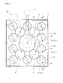
- [FIG. 2] FIG. 2 is a top view showing the fastening tool.
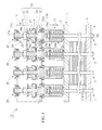
- [FIG. 3] FIG. 3 is a cross-sectional view taken along the line A-A in FIG. 2.
- [FIG. 4] FIG. 4 is an exploded explanatory view showing a torque wrench of the above fastening tool.
-
- 2
- Unit cell
- 5
- Fastening member
- 10
- Fastening tool for a fuel cell
- 11
- Frame
- 12
- Handle (Torque input device)
- 15
- Torque transmission mechanism
- 21
- Input rotor (i.e., rotor)
- 22
- Socket member
- 23
- Clutch mechanism
- 31,32
- Washers
- 33, 34
- Disc springs
- 35
- Nut
- An embodiment of the present invention will now be described with reference made to the drawings.
A fastening tool for a fuel cell indicated by thesymbol 10 in FIG. 1 is formed so that, when afuel cell 1 is being assembled, a large number of stackedunit cells 2 are fastened in a stacking direction using a plurality of fasteningmembers 5. - The
fuel cell 1 is a known polymer electrolyte fuel cell 1 (PEFC) that is formed by stacking a large number of rectangular plate-shaped unit cells (i.e., unit cells) 2 and then sandwiching these between a pair offastening plates members 5 are provided in parallel rows around thefuel cell 1. Both end portions of eachfastening member 5 are connected to outer peripheral portions of therespective fastening plates members 5 generate fastening force that compresses the space between therespective fastening plates - Four of the
respective fastening members 5 are aligned substantially equidistantly along the long sides of theunit cells 2 and three are aligned substantially equidistantly along the short sides of theunit cells 2, so that a total of ten fasteningmembers 5 are provided for onefuel cell 1. The fastening force of eachfastening member 5 is imparted via the twofastening plates respective unit cells 2 so that uniform surface pressure is generated in therespective unit cells 2. - A description will now be given with reference made to FIG. 3. Each fastening
member 5 is principally formed by astud bolt 6 that penetrates therespective fastening plates unit cells 2 and by anut 7 that is threaded onto thestud bolt 6. By employing a structure in which acompression coil spring 8 is interposed between thenut 7 and thefastening plate 3, theunit cells 2 are resiliently fastened. Hereinafter, the stacking direction of theunit cells 2 is taken as a vertical direction with thehead portion 6a side (i.e., thefastening plate 4 side) of thestud bolts 6 taken as the downward side and thenut 7 side (i.e., thefastening plate 3 side) taken as the upward side. - Shaft portions of the
stud bolts 6 penetrate thefastening plates fastening plate 4, which is on the bottom side, towards the top of thefastening plate 3, which is on the top side. Thenut 7 is threaded onto the portion of thestud bolts 6 that protrudes upwards from the topside fastening plate 3, and thecompression coil springs 8 are interposed between thenut 7 and thefastening plate 3. - A bottom end of the
compression coil springs 8 is placed against a top surface of thefastening plate 3, while a top surface thereof is placed via aflat washer 9 against a bottom surface of thenut 7. As a result of the resilient force of thiscompression coil spring 8 in its direction of expansion, the topside fastening plate 3 is urged downwards and the bottomside fastening plate 4 is urged upwards via thenut 7 and thestud bolt 6. Accordingly, the twofastening plates unit cells 2 between them. - Namely, if the
nut 7 is loosened, the resilient force of thecompression coil spring 8 is reduced so that the fastening force of thefastening member 5 is reduced. If thenut 7 is tightened, the resilient force of thecompression coil spring 8 is increased so that the fastening force of thefastening member 5 is increased. Here, the torque that is required to tighten the nut 7 (i.e., the tightening torque) increases or decreases in proportion to the increase or decrease of the resilient force of thecompression coil spring 8. In other words, the tightening torque increases or decreases in accordance with the reaction force received from theunit cells 2 that have been fastened by thefastening members 5. - The
fastening tool 10 receives an input of torque from a single handle (i.e., torque input device) 12 and by simultaneously operating a plurality oftorque wrenches 20 that are provided for therespective fastening members 5, this torque is divided between therespective fastening members 5 and thenuts 7 of therespective fastening members 5 are tightened with a predetermined tightening torque. - As is shown in FIGS. 1 and 2, the
fastening tool 10 is provided with a box-shapedframe 11 that, in a top view, presents a flat, rectangular parallelepiped-shaped external appearance in a vertical direction substantially superimposed on therespective fastening plates torque input shaft 13 having an axis of rotation that runs in the vertical direction is placed in a center portion of theframe 11. The plurality oftorque wrenches 20 that also have an axis of rotation running in the vertical direction are placed at outer peripheral portions of theframe 11. - The
torque input shaft 13 is supported so as to be able to rotate freely in theframe 11. A top end portion of thetorque input shaft 13 protrudes upward from atop wall portion 11a of theframe 11 and is connected to a base portion of thehandle 12. Namely, by operating thehandle 12, the desired torque can be input into thetorque input shaft 13.
The torque that is input into theinput shaft 13 is divided via atorque transmission mechanism 15 that is formed by a plurality of gears. The divided torque is transmitted to input rotors (i.e., rotors) 21 of therespective torque wrenches 20. - The
torque transmission mechanism 15 has aninput gear 16 that is coaxially fixed to thetorque input shaft 13,intermediate gears 17 that are located in four directions around theinput gear 16 and mesh with theinput gear 16, and output gears 18 that mesh with the adjacentintermediate gear 17. The output gears 18 are formed integrally with theinput rotors 21 of therespective torque wrenches 20. Theinput gear 16 is formed larger than theintermediate gears 17 and the output gears 18, and increases the angular velocity of therespective torque wrenches 20 relative to the angular velocity of thehandle 12. - The respective
intermediate gears 17 are supported so as to be freely rotatable in theframe 11 and are each placed so as to mesh with a total of three output gears 18, namely, those of thetorque wrench 20 positioned in the corner of theframe 11 and of the twotorque wrenches 20 positioned adjacent to this. Accordingly, thecenter output gear 18 from among the threetorque wrenches 20 positioned along the short side of theunit cells 2 meshes with twointermediate gears 17. - If torque is input in a rightward direction (as seen in top view) into the
torque input shaft 13 using thehandle 12, then the same rightward torque is transmitted via theinput gear 16, the respectiveintermediate gears 17, and the respective output gears 18 to theinput rotors 21 of therespective torque wrenches 20 so that therespective input rotors 21 are rotated in the same manner. Namely, therespective torque wrenches 20 operate in conjunction with the rotation of thetorque input shaft 13. - As is shown in FIGS. 3 and 4, each
torque wrench 20 has asocket member 22 that engages with thenut 7 of thecorresponding fastening member 5 such that it can transmit torque thereto, theinput rotor 21, and aclutch mechanism 23 that is interposed between theinput rotor 21 and thesocket member 22 and controls the transmission of torque between them. - The
socket member 22 is supported so as to be able to rotate freely in theframe 11, and is made up of asocket body 24 that is provided so as to protrude downwards from abottom wall portion 11b of theframe 11, a bottomside supporting portion 25 that is continuous from a top end of thesocket body 24, aninput shaft portion 26 that is continuous from a top end of the bottomside supporting portion 25, and a topside supporting portion 27 that is continuous from a top end of theinput shaft portion 26 that are all formed integrally with each other. - The
socket body 24 is formed as a circular cylinder having one closed end that opens in a downwards direction, and has a comparatively thickbottom wall portion 24a and a comparatively thincircumferential wall portion 24b. The axis of rotation of thesocket body 24 matches the axis of rotation of thesocket member 22. If thesocket body 24 is fitted onto thefastening member 5 so as to cover thecompression coil spring 8 of thefastening member 5, then thenut 7 fits inside aconcave portion 24c that is formed in a center of a bottom surface of thebottom wall portion 24a. Note that aguide surface 24d that guides thenut 7 when it is being fitted is formed on a peripheral edge on the aperture side of theconcave portion 24c. - The bottom
side supporting portion 25 is formed coaxially with thesocket body 24 as a small diameter circular column. The bottomside supporting portion 25 is supported such that it can rotate freely on thebottom wall portion 11b of theframe 11 via abearing 28 that is fitted onto the outer circumferential surface thereof. - The
input shaft portion 26 is shaped as a rod that extends from a top end of the bottomside supporting portion 25 to the vicinity of thetop wall portion 11a of theframe 11, and is formed having a substantially D-shaped cross section by being provided with a flatbeveled portion 26a on one side of a circular column that is coaxial with thesocket member 22. A male threadedportion 26b having thread ridges on its outer circumferential portion is formed on the top end portion of theinput shaft portion 26. - The top
side supporting portion 27 has a circular column shape that is coaxial with theinput shaft portion 26, and is supported such that it can rotate freely on thetop wall portion 11a of theframe 11 via abearing 29 that is fitted onto the outer circumferential surface thereof. A C-clip 27a is mounted on a top end portion of the topside supporting portion 27. As a result of the C-clip 27a and the top end portion of thesocket body 24 coming into contact with theframe 11 via flange portions of therespective bearings socket member 22 is positioned in the vertical direction relative to theframe 11. - The input rotors 21 are supported on the
input shaft portion 26 of thesocket member 22 such that they can rotate freely around the axis of rotation of thesocket member 22. The input rotors 21 are shaped as circular cylinders through which theinput shaft portions 26 can be inserted, and the output gears 18 are formed integrally with an outer circumferential portion of the bottom portion thereof. - Disc-shaped
thick washers input rotors 21. Thesethick washers insertion holes input shaft portions 26. By inserting aninput shaft portion 26 through theinsertion holes thick washers input shaft portion 26 in a state in which they are allowed to make relative movements in the vertical direction relative to theinput shaft portion 26, however, any relative rotation thereof around the axis of rotation is restricted. - A plurality of disc-
springs input rotor 21 and the respectivethick washers input rotor 21 and the top sidethick washer 31. Three disc springs 34 whose outer circumferential side is positioned lower than their center side are stacked between theinput rotor 21 and the bottom sidethick washer 32.
Note that in the present embodiment the disc springs 33 and 34 are placed above and below theinput rotor 21, however, the disc spring is also possible to be placed either above or below theinput rotor 21. - A
wrench nut 35 is threaded onto the male threadedportion 26b of theinput shaft 26. The top sidethick washer 31 and the two disc springs 33 are placed between the bottom surface of thewrench nut 35 and the top surface of theinput rotor 21. In contrast, the bottom sidethick washer 32 and the three disc springs 34 are placed between the top surface of the bottomside supporting portion 25 and the bottom surface of theinput rotor 21. Namely, the respectivethick washers input rotor 21 that are placed between the bottom surface of thewrench nut 35 and the top surface of the bottomside supporting portion 25 are held by thewrench nut 35 and the bottomside supporting portion 25. - If the
wrench nut 35 is tightened so that a predetermined resilient force is generated in the respective disc springs 33 and 34, then the respectivethick washers input rotor 21 are engaged by friction via the respective disc springs 33 and 34. As a result, it becomes possible for torque to be transmitted between theinput rotor 21 and thesocket member 22. Namely, the respectivethick washers clutch mechanism 23 that is interposed between theinput rotor 21 and thesocket member 22. - This type of
clutch mechanism 23 adjusts the amount that thewrench nut 35 is tightened on the male threadedportion 26b and changes the resilient force of the disc springs 33 and 34, thereby resulting in the friction engagement (i.e., the clutch capacity) between theinput rotor 21 and thesocket member 22 being increased or decreased. Namely, when a top limit value is set for the tightening torque that can be transmitted between theinput rotor 21 and thesocket member 22 and torque that exceeds this top limit value is applied, theclutch mechanism 23 is made to slip and theinput rotor 21 andsocket member 22 are rotated relatively to each other, resulting in it not being possible to transmit torque between them. - As has been described above, the
fastening tool 10 for a fuel cell of the above described example is used to simultaneously fasten a large number ofstacked unit cells 2 using a plurality offastening members 5. Thisfastening tool 10 for a fuel cell is provided with thesocket members 22 that are provided so as to correspond to eachfastening member 5 and are engaged such that they can transmit torque to thefastening members 5, thetorque transmission mechanism 15 that divides torque that is input from the torque input device in the form of thehandle 12 and transmits it to theinput rotors 21 that are provided to correspond to eachsocket member 22, and theclutch mechanisms 23 that are provided respectively between eachsocket member 22 andinput rotor 21. Theclutch mechanism 23 is constructed so as to cause thesocket members 22 to rotate together with theinput rotors 21 when the torque required to tighten thefastening member 5 is equal to or less than a predetermined value, and so as to cause theinput rotors 21 to rotate idly relative to thesocket members 22 when the torque is larger than a predetermined value. - According to this structure, when a
fuel cell 1 is being assembled, after therespective fastening members 5 have been temporarily joined to the stackedunit cells 2, they are simultaneously tightened. As a result, it is possible to maintain a uniform fastening force in eachfastening member 5 and apply surface pressure evenly to theunit cells 2.
Because of this, when assembling afuel cell 1, an operation to fasten stackedunit cells 2 using separate pressing machines or the like is unnecessary, and it is possible to maintain a uniform fastening force in eachfastening member 5 and apply surface pressure evenly to theunit cells 2. Accordingly, the effect is obtained that the number of steps needed to assemble thefuel cell 1 can be decreased. - Moreover, even if there are differences in the temporary joining state of the respective fastening members 5 (for example, the amount that each
nut 7 has been threaded onto the stud bolts 6), if the torque required to tighten thefastening members 5 reaches a predetermined value, in other words, if the fastening force of thefastening members 5 reaches the predetermined value, then because theclutch mechanism 23 allows theinput rotors 21 to rotate idly relative to thesocket members 22, the result is that simply by inputting torque until all of theinput rotors 21 are rotating idly, any unevenness in the temporary joining state of therespective fastening members 5 is absorbed, and they can be simultaneously and uniformly tightened.
As a result, the effect is obtained that, in combination with the above described operating effects, it is possible to greatly decrease the number of steps required to assemble thefuel cell 1. - Note that this invention is not limited to the above described example. For example, it is also possible to employ an electric motor type or pneumatic type or the like of torque input device instead of using the
handle 12. Moreover, the adjustment of the fastening force of thefastening member 5 can be performed not on thenut 7 side, but by tightening thehead portion 6a side of thestud bolt 6. Furthermore, thetorque transmission mechanism 15 may also be formed by a combination of a chain and sprocket or by a combination of a belt and pulley. Furthermore, it is also possible to employ a structure in which the urging device for theclutch mechanism 23 does not use disc springs but coil springs, however, from the standpoint of it being possible to suppress the entire length in the vertical direction of eachtorque wrench 20, it is desirable for disc springs to be used.
It is also possible to provide a guide or the like in theframe 11 in order to stabilize thefuel cell 1. For example, by extending the side surfaces of theframe 11 to the socket member side so as to provide a frame-shaped guide, thefuel cell 1 can be fitted in the inner side of this guide. Therefore, theframe 11 can be stabilized and thefuel cell 1 can be fastened.
Moreover, in the present embodiment a fuel cell is used as an object fastened by a fastening tool, however, the fastened object is not limited to a fuel cell.
In addition, the structure in the above described example is only one example and it should be understood that various modifications can be made without departing from the scope of the present invention. Additions, omissions, substitutions, and other modifications can be made without departing from the spirit or scope of the present invention. Accordingly, the invention is not to be considered as limited by the foregoing description and is only limited by the scope of the appended claims. - According to the present invention, when assembling a fuel cell, an operation to fasten stacked unit cells using separate pressing machines or the like is unnecessary, and it is possible to maintain a uniform fastening force in each fastening member and apply surface pressure evenly to the unit cells. In addition, any unevenness in the temporary joining state of the respective fastening members is absorbed, and they can be simultaneously and uniformly tightened. As a result, it is possible to greatly decrease the number of steps required to assemble a fuel cell.
Claims (4)
- A fastening tool for a fuel cell comprising:a plurality of socket members that are engaged so as to be able to transmit torque individually to a plurality of fastening members for simultaneously fastening a large number of stacked unit cells;rotors that are provided individually on each of the socket members;a torque input device that inputs torque for rotating the respective rotors;a torque transmission mechanism that divides torque that is input from the torque input device and transmits it to the respective rotors so as to cause each rotor to rotate uniformly; andclutch mechanisms that are individually provided between the respective socket members and rotors and cause the socket members to rotate together with the rotors when a tightening torque that causes the rotors to rotate is equal to or less than a predetermined value, and cause the rotors to rotate idly relative to the socket members when the tightening torque is greater than the predetermined value.
- The fastening tool for a fuel cell according to claim 1, wherein:the clutch mechanisms comprise:washers that are placed at one end in an axial rotation direction of the rotors and rotate integrally with the rotors; anddisc springs that are placed between the rotors and the washers and are compressed.
- The fastening tool for a fuel cell according to claim 2, further comprising nuts that change a resilient force of the disc springs.
- The fastening tool for a fuel cell according to claim 1, further comprising a box-shaped frame that supports the socket members and the torque input device so as to rotate freely, and that houses the clutch mechanism.
Applications Claiming Priority (2)
| Application Number | Priority Date | Filing Date | Title |
|---|---|---|---|
| JP2004156327A JP4667766B2 (en) | 2004-05-26 | 2004-05-26 | Fastening tool for fuel cell |
| PCT/JP2005/007441 WO2005117194A1 (en) | 2004-05-26 | 2005-04-19 | Fastening tool for fuel cell |
Publications (2)
| Publication Number | Publication Date |
|---|---|
| EP1753065A1 true EP1753065A1 (en) | 2007-02-14 |
| EP1753065A4 EP1753065A4 (en) | 2010-03-24 |
Family
ID=35451188
Family Applications (1)
| Application Number | Title | Priority Date | Filing Date |
|---|---|---|---|
| EP05734635A Withdrawn EP1753065A4 (en) | 2004-05-26 | 2005-04-19 | FIXING TOOL FOR FUEL CELL |
Country Status (3)
| Country | Link |
|---|---|
| EP (1) | EP1753065A4 (en) |
| JP (1) | JP4667766B2 (en) |
| WO (1) | WO2005117194A1 (en) |
Cited By (12)
| Publication number | Priority date | Publication date | Assignee | Title |
|---|---|---|---|---|
| WO2012176032A1 (en) * | 2011-06-21 | 2012-12-27 | Toyota Jidosha Kabushiki Kaisha | Multi-axis temporary tightening tool |
| FR3012189A1 (en) * | 2013-10-22 | 2015-04-24 | Ct Tech Des Ind Mecaniques | MULTI-SLEEVE CLAMPING DEVICE |
| US20170033392A1 (en) * | 2015-07-31 | 2017-02-02 | Hyundai Motor Company | Apparatus for assembling fuel cell stack |
| CN108202220A (en) * | 2017-12-29 | 2018-06-26 | 王建林 | A kind of circuit breaker base automatic screw fixing machine |
| WO2019089414A1 (en) * | 2017-11-01 | 2019-05-09 | Superbolt, Inc. | A system for simultaneously pre-set torqueing and tensioning a multi-jackbolt tensioner |
| DE102018210176A1 (en) * | 2018-06-22 | 2019-12-24 | Audi Ag | fuel cell stack |
| DE102018210179A1 (en) * | 2018-06-22 | 2019-12-24 | Audi Ag | fuel cell stack |
| WO2019242932A1 (en) * | 2018-06-22 | 2019-12-26 | Audi Ag | Fuel cell stack |
| WO2020126100A1 (en) * | 2018-12-21 | 2020-06-25 | Caterpillar Energy Solutions Gmbh | Apparatus for simultaneously actuating at least two screw tensioning devices |
| CN111941054A (en) * | 2020-09-11 | 2020-11-17 | 意华控股集团有限公司 | Automatic screw locking device |
| CN113732678A (en) * | 2020-05-29 | 2021-12-03 | 盟立自动化股份有限公司 | Disassembling and assembling equipment |
| TWI755142B (en) * | 2020-05-29 | 2022-02-11 | 盟立自動化股份有限公司 | Assembly and disassembly equipment |
Families Citing this family (8)
| Publication number | Priority date | Publication date | Assignee | Title |
|---|---|---|---|---|
| KR100710274B1 (en) | 2005-12-29 | 2007-04-20 | 재단법인서울대학교산학협력재단 | Fastening Structure of Fuel Cell Stack |
| KR100746270B1 (en) | 2006-01-20 | 2007-08-03 | 재단법인서울대학교산학협력재단 | Fastening device of fuel cell stack |
| JP4989161B2 (en) * | 2006-09-08 | 2012-08-01 | 本田技研工業株式会社 | Fuel cell stack |
| JP5039494B2 (en) * | 2007-10-03 | 2012-10-03 | 本田技研工業株式会社 | Pinning tool for fastening fuel cell |
| JP6467681B2 (en) * | 2014-12-26 | 2019-02-13 | マグネクス株式会社 | Solid oxide fuel cell |
| CN106964973A (en) * | 2017-05-17 | 2017-07-21 | 深圳市山龙智控有限公司 | Screwed lock pays mechanism and filature |
| CN108637304A (en) * | 2018-05-24 | 2018-10-12 | 西安航空职业技术学院 | A kind of numerical control processing apparatus |
| CN110900175A (en) * | 2019-11-21 | 2020-03-24 | 安徽枫雅轩科技信息服务有限公司 | Battery module assembly fixture |
Family Cites Families (17)
| Publication number | Priority date | Publication date | Assignee | Title |
|---|---|---|---|---|
| DE1628024A1 (en) * | 1967-06-21 | 1971-11-25 | Vickers Zimmer Ag | Device for tightening screw connections, especially on spinnerets |
| GB1462759A (en) * | 1973-10-10 | 1977-01-26 | Neil Holdings Ltd James | Torque wrenches |
| SU975303A1 (en) * | 1981-07-10 | 1982-11-23 | Рязанский Филиал Центрального Конструкторско-Технологического Бюро Госкомсельхозтехники Рсфср | Multispindle power nut driver |
| JPS5989814A (en) * | 1982-11-12 | 1984-05-24 | 株式会社日立製作所 | Fixed-torque clamping screw |
| JPS59108279A (en) * | 1982-12-10 | 1984-06-22 | Sanyo Electric Co Ltd | Compression device for fuel cell stack and its compression method |
| DE3344600C2 (en) * | 1983-12-09 | 1986-06-19 | Helfer & Co KG, 3260 Rinteln | Screw head |
| DE3421596A1 (en) * | 1984-06-09 | 1985-12-12 | Helfer & Co KG, 3260 Rinteln | SCREW ATTACHMENT |
| DE3443072A1 (en) * | 1984-11-26 | 1986-05-28 | Rudolf Dipl.-Ing. Höpfner (FH), 8500 Nürnberg | Torque limiter |
| DE19829960C2 (en) * | 1998-07-04 | 2000-06-21 | Norbert Felder | Torque limiting device |
| JP4083304B2 (en) * | 1998-08-20 | 2008-04-30 | 松下電器産業株式会社 | Polymer electrolyte fuel cell |
| JP3420508B2 (en) * | 1998-08-20 | 2003-06-23 | 松下電器産業株式会社 | Polymer electrolyte fuel cell |
| JP2000208163A (en) * | 1999-01-19 | 2000-07-28 | Ishikawajima Harima Heavy Ind Co Ltd | Fuel cell fastening device |
| US6134989A (en) * | 1999-02-03 | 2000-10-24 | Stevens; Gerald | Multi-lug nut driving device |
| US6253644B1 (en) * | 1999-03-02 | 2001-07-03 | David M. Duquette | Torque wrench |
| US6428921B1 (en) * | 1999-10-22 | 2002-08-06 | General Motors Corporation | Fuel cell stack compression method and apparatus |
| JP4227736B2 (en) * | 2001-04-04 | 2009-02-18 | 三菱重工業株式会社 | Solid polymer water electrolysis cell structure |
| US6834567B2 (en) * | 2002-06-11 | 2004-12-28 | General Motors Corporation | Multiple torque adjustable spindles with a single drive motor |
-
2004
- 2004-05-26 JP JP2004156327A patent/JP4667766B2/en not_active Expired - Fee Related
-
2005
- 2005-04-19 WO PCT/JP2005/007441 patent/WO2005117194A1/en not_active Ceased
- 2005-04-19 EP EP05734635A patent/EP1753065A4/en not_active Withdrawn
Cited By (19)
| Publication number | Priority date | Publication date | Assignee | Title |
|---|---|---|---|---|
| WO2012176032A1 (en) * | 2011-06-21 | 2012-12-27 | Toyota Jidosha Kabushiki Kaisha | Multi-axis temporary tightening tool |
| CN103619531A (en) * | 2011-06-21 | 2014-03-05 | 丰田自动车株式会社 | Multi-axis temporary tightening tool |
| CN103619531B (en) * | 2011-06-21 | 2016-03-16 | 丰田自动车株式会社 | Multi-shaft temporary fastening tool |
| FR3012189A1 (en) * | 2013-10-22 | 2015-04-24 | Ct Tech Des Ind Mecaniques | MULTI-SLEEVE CLAMPING DEVICE |
| US20170033392A1 (en) * | 2015-07-31 | 2017-02-02 | Hyundai Motor Company | Apparatus for assembling fuel cell stack |
| US10170785B2 (en) * | 2015-07-31 | 2019-01-01 | Hyundai Motor Company | Apparatus for assembling fuel cell stack |
| WO2019089414A1 (en) * | 2017-11-01 | 2019-05-09 | Superbolt, Inc. | A system for simultaneously pre-set torqueing and tensioning a multi-jackbolt tensioner |
| CN108202220A (en) * | 2017-12-29 | 2018-06-26 | 王建林 | A kind of circuit breaker base automatic screw fixing machine |
| DE102018210176A1 (en) * | 2018-06-22 | 2019-12-24 | Audi Ag | fuel cell stack |
| DE102018210179A1 (en) * | 2018-06-22 | 2019-12-24 | Audi Ag | fuel cell stack |
| WO2019242932A1 (en) * | 2018-06-22 | 2019-12-26 | Audi Ag | Fuel cell stack |
| US11791492B2 (en) | 2018-06-22 | 2023-10-17 | Volkswagen Ag | Fuel cell stack |
| US11817611B2 (en) | 2018-06-22 | 2023-11-14 | Volkswagen Ag | Fuel cell stack |
| WO2020126100A1 (en) * | 2018-12-21 | 2020-06-25 | Caterpillar Energy Solutions Gmbh | Apparatus for simultaneously actuating at least two screw tensioning devices |
| GB2580107A (en) * | 2018-12-21 | 2020-07-15 | Caterpillar Energy Solutions Gmbh | Apparatus for simultaneously actuating at least two screw tensioning devices |
| GB2580107B (en) * | 2018-12-21 | 2021-04-28 | Caterpillar Energy Solutions Gmbh | Apparatus for simultaneously actuating at least two screw tensioning devices |
| CN113732678A (en) * | 2020-05-29 | 2021-12-03 | 盟立自动化股份有限公司 | Disassembling and assembling equipment |
| TWI755142B (en) * | 2020-05-29 | 2022-02-11 | 盟立自動化股份有限公司 | Assembly and disassembly equipment |
| CN111941054A (en) * | 2020-09-11 | 2020-11-17 | 意华控股集团有限公司 | Automatic screw locking device |
Also Published As
| Publication number | Publication date |
|---|---|
| WO2005117194A1 (en) | 2005-12-08 |
| JP2005339958A (en) | 2005-12-08 |
| JP4667766B2 (en) | 2011-04-13 |
| EP1753065A4 (en) | 2010-03-24 |
Similar Documents
| Publication | Publication Date | Title |
|---|---|---|
| EP1753065A1 (en) | Fastening tool for fuel cell | |
| US8480527B2 (en) | Gearing arrangement | |
| KR101583703B1 (en) | Reducer endurance test apparatus | |
| GB2476376A (en) | Power drill | |
| WO2007084289A3 (en) | Power closure actuator | |
| JP5873990B2 (en) | Compressor fixing structure | |
| JP2017512952A (en) | Brake gear motor group | |
| WO2006112163A1 (en) | Propulsion force transmission device | |
| JP7674780B2 (en) | Variable planetary carrier system and planetary transmission equipped with the same | |
| TW202348494A (en) | Drive arrangement | |
| KR20130008356A (en) | In-wheel working device | |
| TWM632933U (en) | A drive arrangement, a frame element for receiving such drive arrangement and a vehicle comprising such drive arrangement | |
| US20100113198A1 (en) | Tensioning device pertaining to a traction mechanism drive | |
| JP2012177335A (en) | Fixing structure of compressor | |
| EP2412996A1 (en) | Friction clutch | |
| JP2021028520A (en) | Damper device | |
| EP3343195B1 (en) | Rotation pulsation generating mechanism | |
| JP2010174966A (en) | Fixing device of power transmitting member for air conditioner | |
| KR0134720Y1 (en) | Torque limiter device for power transmission | |
| US20230211487A1 (en) | Power tool and clutch assembly thereof | |
| CN218747533U (en) | Mounting tool for locking nut of main shaft bearing of engine | |
| US20050100397A1 (en) | Power transmission mechanism and process of assembling the same | |
| CN109844365B (en) | Planetary gear speed reducer for ultra-high speed reduction | |
| JP2013072556A (en) | Crankshaft accessory used as torque variation absorbing damper or vibration isolation belt pulley | |
| EP3898107B1 (en) | Apparatus for simultaneously actuating at least two screw tensioning devices |
Legal Events
| Date | Code | Title | Description |
|---|---|---|---|
| PUAI | Public reference made under article 153(3) epc to a published international application that has entered the european phase |
Free format text: ORIGINAL CODE: 0009012 |
|
| 17P | Request for examination filed |
Effective date: 20061117 |
|
| AK | Designated contracting states |
Kind code of ref document: A1 Designated state(s): DE FR GB |
|
| DAX | Request for extension of the european patent (deleted) | ||
| A4 | Supplementary search report drawn up and despatched |
Effective date: 20100219 |
|
| RIC1 | Information provided on ipc code assigned before grant |
Ipc: H01M 8/10 20060101ALI20100215BHEP Ipc: B25B 21/00 20060101ALN20100215BHEP Ipc: B25B 23/14 20060101ALI20100215BHEP Ipc: H01M 8/24 20060101AFI20051216BHEP Ipc: B23P 19/06 20060101ALI20100215BHEP |
|
| STAA | Information on the status of an ep patent application or granted ep patent |
Free format text: STATUS: THE APPLICATION HAS BEEN WITHDRAWN |
|
| 18W | Application withdrawn |
Effective date: 20100423 |