EP1753062A1 - Système à pile à combustible et methode pour déterminer/côntroler le débit d'oxydant dans ledit système - Google Patents
Système à pile à combustible et methode pour déterminer/côntroler le débit d'oxydant dans ledit système Download PDFInfo
- Publication number
- EP1753062A1 EP1753062A1 EP06117233A EP06117233A EP1753062A1 EP 1753062 A1 EP1753062 A1 EP 1753062A1 EP 06117233 A EP06117233 A EP 06117233A EP 06117233 A EP06117233 A EP 06117233A EP 1753062 A1 EP1753062 A1 EP 1753062A1
- Authority
- EP
- European Patent Office
- Prior art keywords
- fuel cell
- oxidizer
- cell system
- volume flow
- control
- Prior art date
- Legal status (The legal status is an assumption and is not a legal conclusion. Google has not performed a legal analysis and makes no representation as to the accuracy of the status listed.)
- Withdrawn
Links
- 239000000446 fuel Substances 0.000 title claims abstract description 111
- 239000007800 oxidant agent Substances 0.000 title claims abstract description 96
- 238000000034 method Methods 0.000 title claims abstract description 24
- 230000001590 oxidative effect Effects 0.000 title claims abstract description 13
- 230000001105 regulatory effect Effects 0.000 claims description 18
- 210000004027 cell Anatomy 0.000 description 74
- XLYOFNOQVPJJNP-UHFFFAOYSA-N water Substances O XLYOFNOQVPJJNP-UHFFFAOYSA-N 0.000 description 31
- OKKJLVBELUTLKV-UHFFFAOYSA-N Methanol Chemical compound OC OKKJLVBELUTLKV-UHFFFAOYSA-N 0.000 description 30
- 239000001301 oxygen Substances 0.000 description 8
- 229910052760 oxygen Inorganic materials 0.000 description 8
- QVGXLLKOCUKJST-UHFFFAOYSA-N atomic oxygen Chemical compound [O] QVGXLLKOCUKJST-UHFFFAOYSA-N 0.000 description 7
- LFQSCWFLJHTTHZ-UHFFFAOYSA-N Ethanol Chemical compound CCO LFQSCWFLJHTTHZ-UHFFFAOYSA-N 0.000 description 6
- 238000001816 cooling Methods 0.000 description 6
- 230000001276 controlling effect Effects 0.000 description 5
- 239000000203 mixture Substances 0.000 description 4
- 229920005597 polymer membrane Polymers 0.000 description 4
- 238000010521 absorption reaction Methods 0.000 description 3
- 239000003990 capacitor Substances 0.000 description 3
- 238000006243 chemical reaction Methods 0.000 description 3
- 230000005611 electricity Effects 0.000 description 3
- 239000012530 fluid Substances 0.000 description 3
- 239000007789 gas Substances 0.000 description 3
- 230000003647 oxidation Effects 0.000 description 3
- 238000007254 oxidation reaction Methods 0.000 description 3
- UFHFLCQGNIYNRP-UHFFFAOYSA-N Hydrogen Chemical compound [H][H] UFHFLCQGNIYNRP-UHFFFAOYSA-N 0.000 description 2
- 238000010586 diagram Methods 0.000 description 2
- 239000001257 hydrogen Substances 0.000 description 2
- 229910052739 hydrogen Inorganic materials 0.000 description 2
- 239000007788 liquid Substances 0.000 description 2
- 238000004519 manufacturing process Methods 0.000 description 2
- 239000012528 membrane Substances 0.000 description 2
- 239000007864 aqueous solution Substances 0.000 description 1
- 210000000170 cell membrane Anatomy 0.000 description 1
- 238000002485 combustion reaction Methods 0.000 description 1
- 239000000470 constituent Substances 0.000 description 1
- 230000006735 deficit Effects 0.000 description 1
- 230000018044 dehydration Effects 0.000 description 1
- 238000006297 dehydration reaction Methods 0.000 description 1
- 230000001419 dependent effect Effects 0.000 description 1
- 239000012078 proton-conducting electrolyte Substances 0.000 description 1
- 238000004064 recycling Methods 0.000 description 1
- 238000007493 shaping process Methods 0.000 description 1
- 239000000243 solution Substances 0.000 description 1
Images
Classifications
-
- H—ELECTRICITY
- H01—ELECTRIC ELEMENTS
- H01M—PROCESSES OR MEANS, e.g. BATTERIES, FOR THE DIRECT CONVERSION OF CHEMICAL ENERGY INTO ELECTRICAL ENERGY
- H01M8/00—Fuel cells; Manufacture thereof
- H01M8/04—Auxiliary arrangements, e.g. for control of pressure or for circulation of fluids
- H01M8/04082—Arrangements for control of reactant parameters, e.g. pressure or concentration
- H01M8/04089—Arrangements for control of reactant parameters, e.g. pressure or concentration of gaseous reactants
- H01M8/04111—Arrangements for control of reactant parameters, e.g. pressure or concentration of gaseous reactants using a compressor turbine assembly
-
- H—ELECTRICITY
- H01—ELECTRIC ELEMENTS
- H01M—PROCESSES OR MEANS, e.g. BATTERIES, FOR THE DIRECT CONVERSION OF CHEMICAL ENERGY INTO ELECTRICAL ENERGY
- H01M8/00—Fuel cells; Manufacture thereof
- H01M8/04—Auxiliary arrangements, e.g. for control of pressure or for circulation of fluids
- H01M8/04082—Arrangements for control of reactant parameters, e.g. pressure or concentration
- H01M8/04089—Arrangements for control of reactant parameters, e.g. pressure or concentration of gaseous reactants
-
- H—ELECTRICITY
- H01—ELECTRIC ELEMENTS
- H01M—PROCESSES OR MEANS, e.g. BATTERIES, FOR THE DIRECT CONVERSION OF CHEMICAL ENERGY INTO ELECTRICAL ENERGY
- H01M8/00—Fuel cells; Manufacture thereof
- H01M8/04—Auxiliary arrangements, e.g. for control of pressure or for circulation of fluids
- H01M8/04298—Processes for controlling fuel cells or fuel cell systems
- H01M8/04313—Processes for controlling fuel cells or fuel cell systems characterised by the detection or assessment of variables; characterised by the detection or assessment of failure or abnormal function
- H01M8/0438—Pressure; Ambient pressure; Flow
- H01M8/04395—Pressure; Ambient pressure; Flow of cathode reactants at the inlet or inside the fuel cell
-
- H—ELECTRICITY
- H01—ELECTRIC ELEMENTS
- H01M—PROCESSES OR MEANS, e.g. BATTERIES, FOR THE DIRECT CONVERSION OF CHEMICAL ENERGY INTO ELECTRICAL ENERGY
- H01M8/00—Fuel cells; Manufacture thereof
- H01M8/04—Auxiliary arrangements, e.g. for control of pressure or for circulation of fluids
- H01M8/04298—Processes for controlling fuel cells or fuel cell systems
- H01M8/04313—Processes for controlling fuel cells or fuel cell systems characterised by the detection or assessment of variables; characterised by the detection or assessment of failure or abnormal function
- H01M8/0444—Concentration; Density
- H01M8/04447—Concentration; Density of anode reactants at the inlet or inside the fuel cell
-
- H—ELECTRICITY
- H01—ELECTRIC ELEMENTS
- H01M—PROCESSES OR MEANS, e.g. BATTERIES, FOR THE DIRECT CONVERSION OF CHEMICAL ENERGY INTO ELECTRICAL ENERGY
- H01M8/00—Fuel cells; Manufacture thereof
- H01M8/04—Auxiliary arrangements, e.g. for control of pressure or for circulation of fluids
- H01M8/04298—Processes for controlling fuel cells or fuel cell systems
- H01M8/04694—Processes for controlling fuel cells or fuel cell systems characterised by variables to be controlled
- H01M8/04746—Pressure; Flow
- H01M8/04753—Pressure; Flow of fuel cell reactants
-
- H—ELECTRICITY
- H01—ELECTRIC ELEMENTS
- H01M—PROCESSES OR MEANS, e.g. BATTERIES, FOR THE DIRECT CONVERSION OF CHEMICAL ENERGY INTO ELECTRICAL ENERGY
- H01M8/00—Fuel cells; Manufacture thereof
- H01M8/10—Fuel cells with solid electrolytes
- H01M2008/1095—Fuel cells with polymeric electrolytes
-
- H—ELECTRICITY
- H01—ELECTRIC ELEMENTS
- H01M—PROCESSES OR MEANS, e.g. BATTERIES, FOR THE DIRECT CONVERSION OF CHEMICAL ENERGY INTO ELECTRICAL ENERGY
- H01M8/00—Fuel cells; Manufacture thereof
- H01M8/10—Fuel cells with solid electrolytes
- H01M8/1009—Fuel cells with solid electrolytes with one of the reactants being liquid, solid or liquid-charged
- H01M8/1011—Direct alcohol fuel cells [DAFC], e.g. direct methanol fuel cells [DMFC]
-
- Y—GENERAL TAGGING OF NEW TECHNOLOGICAL DEVELOPMENTS; GENERAL TAGGING OF CROSS-SECTIONAL TECHNOLOGIES SPANNING OVER SEVERAL SECTIONS OF THE IPC; TECHNICAL SUBJECTS COVERED BY FORMER USPC CROSS-REFERENCE ART COLLECTIONS [XRACs] AND DIGESTS
- Y02—TECHNOLOGIES OR APPLICATIONS FOR MITIGATION OR ADAPTATION AGAINST CLIMATE CHANGE
- Y02E—REDUCTION OF GREENHOUSE GAS [GHG] EMISSIONS, RELATED TO ENERGY GENERATION, TRANSMISSION OR DISTRIBUTION
- Y02E60/00—Enabling technologies; Technologies with a potential or indirect contribution to GHG emissions mitigation
- Y02E60/30—Hydrogen technology
- Y02E60/50—Fuel cells
Definitions
- the invention relates to a method for determining and / or adjusting the oxidizer volume flow, which is supplied to a cathode device of a fuel cell system, wherein the oxidizer is fed via a driven conveyor of the cathode device.
- the invention further relates to a fuel cell system, comprising at least one fuel cell with an anode device and a cathode device, wherein the anode device fuel and the cathode device oxidizer can be fed.
- the fuel cell system includes a fuel cell having an anode outlet that discharges an H 2 -containing anode exhaust gas and a cathode outlet that discharges an O 2 -containing cathode exhaust gas, a hydrogen source for supplying hydrogen to an anode Anode of the fuel cell, and an air compressor for supplying oxygen to a cathode of the fuel cell. Further, a modulatable pressure regulator is provided downstream of the cathode outlet for changing the backpressure of the cathode exhaust gas.
- the environment around the system is detected and a signal indicating that it is sent to a controller. At least one operating state of the system is detected and a signal indicating it is sent to a controller.
- the controller is modulated by the controller in response to the signals to optimize the performance of the system in the environment.
- an apparatus for controlling the performance of an air-breathing fuel cell having a variable speed compressor disposed in the air supply line to the fuel cell and having an expander disposed in the air discharge line, the compressor and the expander being disposed on a common shaft.
- An expander with variable absorption capacity is used.
- the speed of the compressor and the absorption capacity of the expander are set by a control unit to predetermined setpoints.
- a desired value for the air volume flow is determined, the actual value of the air volume flow adjusted by adjustment of the compressor speed to this target value and the pressure in the cathode compartment of the fuel cell adjusted by adjusting the absorption capacity of the expander to a predetermined operating pressure.
- oxidizer is fed to the cathode device at a constant volume flow.
- the oxidizer is, for example, atmospheric oxygen, which is supplied in an air stream. Is the oxidizer volume flow too high, then an undesirable increased water discharge can take place. An increased power requirement is necessary. It can also be done too much cooling. If the oxidizer flow rate is too low, then electrochemical conversion may not be effective (as it occurs in the oxidizer deficit), and cooling may be too low.
- the invention has for its object to provide a method of the type mentioned, which is carried out in a simple manner.
- This object is achieved in the said method according to the invention in that the back pressure is measured, is conveyed against the oxidizer on the fuel cell system, and from the measured backpressure and one or more drive parameters of the conveyor, the supplied oxidizer flow rate is determined.
- the conveyor which includes, for example, a fan or a compressor is controlled accordingly.
- the one or more drive parameters such as a control voltage of the drive motor, are known.
- the back pressure can be measured via one or more pressure sensors. It has been found that the volume flow has a considerable dependence on both the backpressure and the drive parameter (s) of the conveyor. The back pressure is also variable over time. There may be pressure fluctuations, which are caused for example by water droplets, different moisture levels or clogged channels. Even relatively small pressure fluctuations can have a major influence on the oxidizer volume flow.
- the backpressure is measured directly, and the actual oxidant volume flow is determined from the drive parameter (s). It is then no volume flow sensor necessary. This makes it easy and inexpensive to build the fuel cell system. Furthermore, weight and volume can be reduced.
- the determination of the actual value can be used to build up a control loop.
- the regulatory burden can be kept low.
- the oxidizer volume flow can be regulated in a simple manner by controlling the drive parameter (s).
- the characteristic curve field which characterizes the dependence of the volume flow on the backpressure and the drive parameter (s), can be set up via calibration data which are determined on the fuel cell system.
- the inventive method can be used in a variety of fuel cell types. It can be used, for example, in connection with direct methanol fuel cells or with polymer membrane fuel cells.
- the conveyor comprises a compressor, for example in the form of a fan, an air conveyor or a compressor.
- the compressor is driven accordingly, and preferably one or more drive parameters are adjustable to adjust the power of the compressor and thus the output oxidant volume flow.
- the at least one drive parameter is a control voltage or a control current of a drive of the conveyor.
- a drive parameter can be detected or adjusted in a simple manner.
- the oxidizer volume flow is determined via previously determined calibration data. With measured backpressure and known drive parameters or known drive parameters, the oxidizer volume flow (as actual oxidizer volume flow) can then be read from a characteristic field (corresponding to the calibration data). If an adjustment of the oxidizer volume flow is to take place on a desired oxidizer volume flow, then the directions for the regulation can be determined from the characteristic field of the calibration data; As a result, a desired value can be achieved quickly or during operation, the oxidizer air flow can be effectively maintained at a desired value.
- the calibration data is in a form that characterizes the dependence of the oxidant volume flow on the back pressure and the at least one drive parameter.
- the actual oxidizer volume flow can be determined in a simple manner with known drive parameters or known drive parameters and measured backpressure.
- the oxidizer volume flow is adjusted or adjusted to an operating point or to an operating point range.
- the operating point or operating point range is preferably selected such that a high power efficiency of the fuel cell system with optimized cooling results.
- the operating point or operating point range is determined to be substantially constant. It is particularly provided that the oxidizer is carried out in the superstoichiometric ratio.
- the controlled variable is the oxidizer volume flow.
- the control takes place such that the oxidizer volume flow is at a desired value. It is checked whether there is a deviation between an actual value of the oxidizer volume flow and a desired value.
- the control variable or control variables are the drive parameter (s). These can be easily recorded and adjusted.
- the characteristic curve field of the fuel cell system for the dependence of the volume flow on the counterpressure and the drive parameter (s) can be used to easily determine the direction for the control of the drive parameter (s), if there is a deviation of the actual value from the desired value.
- an actual value of the oxidizer air flow is compared with a desired value of the oxidizer air flow, and the drive parameter (s) are varied until the desired value is reached.
- the variation of the at least one drive parameter preferably takes place on the basis of calibration data, ie a corresponding adjustment of the drive parameter (s) is carried out by the type of deviation (upwards or downwards) and possibly also by the magnitude of the deviation, in order to quickly reach the desired value. To achieve value.
- At least one pressure sensor is provided for measuring the backpressure.
- the at least one pressure sensor is arranged on a supply line to the cathode device in order to detect the back pressure in an effective manner.
- the invention is further based on the object to provide a fuel cell system of the type mentioned, in which the regulatory burden on the Oxidatorzu Equipment is kept low.
- the fuel cell system according to the invention has the advantages already explained in connection with the method according to the invention.
- the fuel cell system according to the invention is, for example, a direct oxidation fuel cell system such as a direct methanol fuel cell system or direct ethanol fuel cell system. It may also be a polymer membrane fuel cell system or another type of fuel cell system.
- the at least one pressure sensor is arranged on a supply line for oxidizer to the cathode device.
- the backpressure can be determined in a simple and effective manner. It is in principle possible that, for example, a suction pump is seated on a discharge line of the cathode device and the backpressure on the suction pump is determined.
- the at least one pressure sensor is connected to the control and / or regulating device in order to provide its data.
- the control and / or regulating device can then determine the actual oxidizer volume flow from a predetermined characteristic field with the data of the pressure sensor.
- control and / or regulating device determines the oxidizer volume flow from one or more drive parameters of the conveyor and the data of the pressure sensor. It is then no volumetric flow sensor necessary.
- control and / or regulating device controls the oxidizer volume flow by controlling one or more drive parameters of the conveyor.
- the drive parameters or the drive parameters can be detected and controlled in a simple manner. For example, it is a control voltage that is easily varied.
- the conveyor device comprises a compressor in order to be able to supply oxidizer to the cathode device.
- the compressor may be a compressor, a fan or an air conveyor.
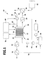
- FIG. 1 An exemplary embodiment of a fuel cell system according to the invention, which is shown in FIG. 1 and designated therein by 10, comprises a fuel cell block 12 (fuel cell stack, fuel cell stack), which has a plurality of fuel cells 14.
- Each fuel cell 14 has a cathode and an anode, wherein the entirety of the anodes of the fuel cell block 12 forms an anode device 16 and the entirety of the cathodes of the fuel cell block 12 forms a cathode device 18.
- a proton-conducting electrolyte is arranged, which is formed for example in the form of a membrane.
- the anodes and the cathodes and thus also the anode device 16 and the cathode device 18 are contacted electrically via a current collector.
- the anode device 16 is assigned a fluid distributor 20 via which fuel can be fed to the anodes of the fuel cell block 12.
- the cathode device 18 is associated with a fluid distributor 22, via which the cathode of the fuel cell block 12 oxidizer can be fed.
- the oxidizer is, for example, atmospheric oxygen, wherein the cathode device 18 is then supplied with an air volume flow.
- the fuel cell system 10 may be a direct oxidation fuel cell system to which fuel is supplied in liquid form.
- DMFC direct methanol fuel cell system
- DEFC direct ethanol fuel cell system
- the fuel cell system 10 may be another type of fuel cell system, such as a polymer membrane fuel cell system (PMFC).
- PMFC polymer membrane fuel cell system
- the fuel cell system 10 will be exemplified as a direct methanol fuel cell system.
- This electricity is produced. Due to the production of electricity fuel consumption and oxidizer consumption occurs.
- Air oxygen is supplied via a feed line 24 of the cathode device 18.
- a conveying device 26 is provided in order to convey the oxidizer and, in particular, to provide a defined volume of the oxidizer and, in particular, an air volume flow to the fuel cell block 12.
- the conveyor 26 is driven by a motor drive. It includes, for example, a fan and / or conveyor and / or compressor.
- the cathode device 18 is associated with a discharge line 28, is discharged through the unconsumed oxidizer; through the discharge line 28 low-oxygen air is removed.
- the discharged fluid contains water.
- the discharge line 28 comprises a capacitor 30 which is connected downstream of the cathode device 18. With the condenser 30, the exhaust product, which comes from the cathode device 18, cool, in particular, water is liquefied.
- the condenser 30 is followed by a water separator 32, by means of which water can be separated from the other constituents.
- the water separator 32 has a first outlet 34, via which gaseous products can be removed. Furthermore, it has a second outlet 36, via which liquid water can be coupled out.
- the anode device 16 is supplied with a fuel-water mixture from a container 38.
- This container 38 is connected via a line 40 on the output side to the anode device 16.
- a pump 42 is arranged to promote the fuel-water mixture.
- a sensor 44 may be provided to determine the amount of fuel in the fuel-water mixture.
- direct methanol fuel cells there is usually an electroosmotic transfer of the fuel from the anode side to the cathode side [fuel crossover or fuel drag].
- On the cathode side there is a direct oxidation of the fuel with oxygen, which is not usable with respect to electricity production.
- the fuel crossover is dependent on the fuel concentration, with the lower fuel concentration being less than the amount of fuel transferred, and therefore the amount of fuel consumed at the anode means 16 is greater than the amount of fuel reacted according to the above equation; Crossover also contributes to fuel consumption at anode device 16.
- a fuel supply 46 fuel can be supplied to the container 38.
- a metering pump 48 is provided for metered supply.
- the container 38 is further coupled via an input to a water supply 50 through which water can be supplied to the container 38 in order to provide a fuel-water mixture can.
- the water separator 32 is coupled with its second outlet 36 directly or indirectly to the water supply 50 in order to keep separated water in the system, d. H. to be able to provide a water cycle.
- water which is supplied by the water separator 32, to be completely or partially separated from the fuel cell system 10.
- the anode device 16 On the output side, the anode device 16 is assigned a capacitor 52, via which products dissipated by the anode device 16 can be cooled.
- This capacitor 52 is followed by a water separator 54.
- water and CO 2 can be separated with the water separator.
- the water separator 54 is connected on the output side via a line 52 to the container 38. As a result, separated water can flow into the container, so that water deposited in the water separator 54 can be held in the fuel cell system 10.
- the power generated by the fuel cell block 12 is delivered to a load 58, wherein a shaping / conversion of the electrical energy may be provided before delivery.
- a control and / or regulating device 60 is provided for controlling and / or regulating the fuel cell system.
- the fuel supply to the anode device 16 is controlled, wherein preferably the fuel crossover is taken into account. For example, it receives data from the sensor 44.
- control and / or regulating device 60 controls or regulates the oxidator supply to the cathode device 18 and in particular controls or regulates the oxidizer volume flow (for example as air volume flow) which is supplied to the cathode device 18.
- a pressure sensor 62 is arranged, through which the back pressure can be determined, against which the oxidizer volume flow must be promoted to the fuel cell system 10.
- pressure fluctuations can occur, which can result, for example, from water droplets, different degrees of humidity or clogged channels. Even relatively small pressure fluctuations can exert a major influence on the oxidizer volume flow. For example, it has been found that pressure fluctuations on the order of 1 mbar can cause an oxidizer volume flow change of the order of about 1%.
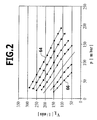
- FIG. 2 shows, for a direct methanol fuel cell system, the dependence of the air volume flow V L as the oxidizer volume flow on the back pressure p for various control voltages of a compressor of the conveyor 26 is shown.
- the upper curve 64 has the highest control voltage (ie, the compressor is operated with the largest power consumption), and the lower curve 66 has the smallest control voltage.
- the upper curve 64 corresponds to a control voltage of 7 volts for the compressor and the lower curve 66 of a control voltage of 4 volts.
- the intervening curves differ by a step of 0.5 volts each.
- the calibration data of the oxidizer volume flow as a function of the backpressure and of the drive parameter or parameters were previously determined on the fuel cell system 10. For this determination, a volume flow sensor can be used.
- a fuel cell system 10 is operated at an oxidizer operating point or in an oxidizer operating point range where oxidant is supplied in a superstoichiometric factor.
- the oxidizer volume flow should be kept constant at the operating point or in the operating point range. It is therefore an adjustment or a regulation of the oxidizer volume flow necessary.
- oxidizer volume flow is too low, then a flooding of the fuel cell 14 can be done with water. There is basically the risk that the fuel cells 14 too little oxidizer is supplied.
- the cooling capacity may be too low and lead to a thermal load of fuel cell membranes.
- an optimized oxidizer volume flow is specified. This forms a target value.
- the actual value of the oxidizer volume flow can be determined by determining the backpressure via the pressure sensor 62 and the drive parameter (s) of the conveyor 26 via calibration data (see FIG. The control and / or regulating device 60 can then check whether there is a deviation between the actual value and the desired value.
- the controlled variable is the oxidizer volume flow, the control variable being the drive parameter or parameters of the conveyor 26. If, for example, the oxidizer volume flow is too high for a given backpressure (which may change over time), then the control voltage for driving the conveyor 26 is reduced. If the actual oxidizer volume flow is too low compared to the set flow rate, then the control voltage is increased.
- the oxidizer volume flow can be set or adjusted to the desired value via the control and / or regulating device 60.
- the actual oxidizer volumetric flow can be determined via the method according to the invention.
- the determination takes place via a characteristic field of the oxidizer volume flow as a function of the drive parameter (s) of the conveyor 26 and the counterpressure, ie by means of the calibration data.
- a simple adjustability or controllability of the oxidizer volume flow to a desired value at an operating point or in an operating point range can be achieved.
- the corresponding fuel cell system can be realized easily and inexpensively as well as with low weight and low volume.
- the adjustment effort or regulatory effort is minimized.
Landscapes
- Life Sciences & Earth Sciences (AREA)
- Engineering & Computer Science (AREA)
- Manufacturing & Machinery (AREA)
- Sustainable Development (AREA)
- Sustainable Energy (AREA)
- Chemical & Material Sciences (AREA)
- Chemical Kinetics & Catalysis (AREA)
- Electrochemistry (AREA)
- General Chemical & Material Sciences (AREA)
- Fuel Cell (AREA)
Applications Claiming Priority (1)
| Application Number | Priority Date | Filing Date | Title |
|---|---|---|---|
| DE102005038455.2A DE102005038455B4 (de) | 2005-08-03 | 2005-08-03 | Verfahren zur Ermittlung und/oder Einstellung des Oxidator-Volumenstroms bei einem Brennstoffzellensystem |
Publications (1)
| Publication Number | Publication Date |
|---|---|
| EP1753062A1 true EP1753062A1 (fr) | 2007-02-14 |
Family
ID=37022955
Family Applications (1)
| Application Number | Title | Priority Date | Filing Date |
|---|---|---|---|
| EP06117233A Withdrawn EP1753062A1 (fr) | 2005-08-03 | 2006-07-14 | Système à pile à combustible et methode pour déterminer/côntroler le débit d'oxydant dans ledit système |
Country Status (2)
| Country | Link |
|---|---|
| EP (1) | EP1753062A1 (fr) |
| DE (1) | DE102005038455B4 (fr) |
Families Citing this family (2)
| Publication number | Priority date | Publication date | Assignee | Title |
|---|---|---|---|---|
| DE102007019361A1 (de) * | 2007-04-23 | 2008-10-30 | J. Eberspächer GmbH & Co. KG | Kalibrierverfahren für eine Brennstoffzellensteuerung |
| JP5924228B2 (ja) | 2012-10-17 | 2016-05-25 | トヨタ自動車株式会社 | 燃料電池システムおよびその制御方法 |
Citations (9)
| Publication number | Priority date | Publication date | Assignee | Title |
|---|---|---|---|---|
| EP0629013A2 (fr) | 1993-06-07 | 1994-12-14 | Daimler-Benz Aktiengesellschaft | Procédé et dispositif pour l'alimentation en air d'un système de piles à combustible |
| EP0993060A2 (fr) * | 1998-10-02 | 2000-04-12 | Toyota Jidosha Kabushiki Kaisha | Dispositif de commande pour pile à combustible et procédé de commande d'une pile à combustible en utilisant un tel dispositif de commande |
| DE10118151A1 (de) | 2000-05-31 | 2001-12-13 | Gen Motors Corporotion Detroit | Brennstoffzelle mit dynamisch geregeltem Gegendruck |
| JP2003168467A (ja) * | 2001-11-30 | 2003-06-13 | Nissan Motor Co Ltd | 車両用燃料電池システムの制御装置 |
| US6586123B1 (en) * | 2001-02-07 | 2003-07-01 | Utc Fuel Cells, Llc | Variable stochiometry fuel cell |
| US6773837B1 (en) * | 1999-05-20 | 2004-08-10 | Honda Giken Kogyo Kabushiki Kaisha | Fuel cell system |
| JP2005038691A (ja) * | 2003-07-14 | 2005-02-10 | Nissan Motor Co Ltd | 燃料電池システムの制御装置 |
| JP2005044737A (ja) | 2003-07-25 | 2005-02-17 | Sumitomo Precision Prod Co Ltd | 直接メタノール型燃料電池の空気流量の制御方法およびその制御装置。 |
| US20050164057A1 (en) * | 2004-01-27 | 2005-07-28 | Peter Pospichal | Virtual compressor operational parameter measurement and surge detection in a fuel cell system |
-
2005
- 2005-08-03 DE DE102005038455.2A patent/DE102005038455B4/de active Active
-
2006
- 2006-07-14 EP EP06117233A patent/EP1753062A1/fr not_active Withdrawn
Patent Citations (9)
| Publication number | Priority date | Publication date | Assignee | Title |
|---|---|---|---|---|
| EP0629013A2 (fr) | 1993-06-07 | 1994-12-14 | Daimler-Benz Aktiengesellschaft | Procédé et dispositif pour l'alimentation en air d'un système de piles à combustible |
| EP0993060A2 (fr) * | 1998-10-02 | 2000-04-12 | Toyota Jidosha Kabushiki Kaisha | Dispositif de commande pour pile à combustible et procédé de commande d'une pile à combustible en utilisant un tel dispositif de commande |
| US6773837B1 (en) * | 1999-05-20 | 2004-08-10 | Honda Giken Kogyo Kabushiki Kaisha | Fuel cell system |
| DE10118151A1 (de) | 2000-05-31 | 2001-12-13 | Gen Motors Corporotion Detroit | Brennstoffzelle mit dynamisch geregeltem Gegendruck |
| US6586123B1 (en) * | 2001-02-07 | 2003-07-01 | Utc Fuel Cells, Llc | Variable stochiometry fuel cell |
| JP2003168467A (ja) * | 2001-11-30 | 2003-06-13 | Nissan Motor Co Ltd | 車両用燃料電池システムの制御装置 |
| JP2005038691A (ja) * | 2003-07-14 | 2005-02-10 | Nissan Motor Co Ltd | 燃料電池システムの制御装置 |
| JP2005044737A (ja) | 2003-07-25 | 2005-02-17 | Sumitomo Precision Prod Co Ltd | 直接メタノール型燃料電池の空気流量の制御方法およびその制御装置。 |
| US20050164057A1 (en) * | 2004-01-27 | 2005-07-28 | Peter Pospichal | Virtual compressor operational parameter measurement and surge detection in a fuel cell system |
Non-Patent Citations (2)
| Title |
|---|
| PATENT ABSTRACTS OF JAPAN vol. 2003, no. 10 8 October 2003 (2003-10-08) * |
| PATENT ABSTRACTS OF JAPAN vol. 2003, no. 12 5 December 2003 (2003-12-05) * |
Also Published As
| Publication number | Publication date |
|---|---|
| DE102005038455B4 (de) | 2016-04-14 |
| DE102005038455A1 (de) | 2007-02-08 |
Similar Documents
| Publication | Publication Date | Title |
|---|---|---|
| DE60030000T2 (de) | Verfahren und vorrichtung zum betrieb einer brennstoffzelle | |
| DE102006019077B4 (de) | Verfahren zur Steuerung der elektrischen Leistungserzeugung in einem Brennstoffzellensystem | |
| EP0629013B2 (fr) | Dispositif pour l'alimentation en air d'un système de piles à combustible | |
| DE102009029837B4 (de) | Brennstoffzellensystem und Verfahren zum Betrieb eines Brennstoffzellensystems mit adaptiver Kompressorpumpsteuerung | |
| DE102017103056B4 (de) | Brennstoffzellensystem und Steuerverfahren für selbiges | |
| DE112006003292B4 (de) | Brennstoffzellensystem und Verwendung des Brennstoffzellelsystems in einem beweglichen Gegenstand | |
| DE112007000808T5 (de) | Brennstoffzellen-Betriebssystem und Ventilöffnungsgrad-Berechnungsverfahren in dem Brennstoffzellen-Betriebssystem | |
| DE102008020102A1 (de) | Anordnung und Verfahren zur Steuerung bzw. Regelung der Feuchtigkeit in einem Brennstoffzellenstapel | |
| DE112007002653B4 (de) | Brennstoffzellensystem | |
| DE112005000767T5 (de) | Brennstoffzellensystem | |
| DE102019103023A1 (de) | Brennstoffzellensystem und verfahren zum steuern einer brennstoffzelle | |
| DE102015215927A1 (de) | Brennstoffzellensystem sowie Verfahren zum Betreiben eines solchen | |
| DE112006002627T5 (de) | Brennstoffzellensystem und Betriebsverfahren für ein Brennstoffzellensystem | |
| DE112005002023T5 (de) | Brennstoffzellensystem und Flüssigkeitsableitungsverfahren für dasselbe | |
| DE102006042037B4 (de) | Brennstoffzellensystem und Verfahren zum Betreiben eines Brennstoffzellensystems | |
| WO2007098782A1 (fr) | Système d'alimentation d'anode pour une pile à combustible et procédé de nettoyage du système d'alimentation d'anode | |
| DE102005038455B4 (de) | Verfahren zur Ermittlung und/oder Einstellung des Oxidator-Volumenstroms bei einem Brennstoffzellensystem | |
| WO2023110475A1 (fr) | Procédé de fonctionnement de système de pile à combustible, et dispositif de commande | |
| DE102011005693B4 (de) | Brennstoffzellensystem und zugehöriges Betriebsverfahren | |
| CH697499B1 (de) | Brennstoffzellenanlage mit einem Kathodenstoffstrom. | |
| EP1454373B1 (fr) | Procede de fonctionnement d'un dispositif de pile a combustible pem et dispositif de pile a combustible correspondant | |
| DE102005033821B4 (de) | Direktoxidations-Brennstoffzellensystem und Verfahren zur Steuerung/Regelung des Wasserhaushalts eines Direktoxidations-Brennstoffzellensystems | |
| DE102014018121A1 (de) | Verfahren zur Brennstoffzufuhr | |
| EP2130260B1 (fr) | Système de pile à combustible et procédé de régulation d'un système de pile à combustible | |
| DE102006048825B4 (de) | Direktoxidations-Brennstoffzellensystem und Verfahren zum Betrieb eines Direktoxidations-Brennstoffzellensystems |
Legal Events
| Date | Code | Title | Description |
|---|---|---|---|
| PUAI | Public reference made under article 153(3) epc to a published international application that has entered the european phase |
Free format text: ORIGINAL CODE: 0009012 |
|
| AK | Designated contracting states |
Kind code of ref document: A1 Designated state(s): AT BE BG CH CY CZ DE DK EE ES FI FR GB GR HU IE IS IT LI LT LU LV MC NL PL PT RO SE SI SK TR |
|
| AX | Request for extension of the european patent |
Extension state: AL BA HR MK YU |
|
| AKX | Designation fees paid | ||
| STAA | Information on the status of an ep patent application or granted ep patent |
Free format text: STATUS: THE APPLICATION IS DEEMED TO BE WITHDRAWN |
|
| 18D | Application deemed to be withdrawn |
Effective date: 20070816 |
|
| REG | Reference to a national code |
Ref country code: DE Ref legal event code: 8566 |