EP1752692A1 - Elektromagnetisch angetriebenes Ventil - Google Patents
Elektromagnetisch angetriebenes Ventil Download PDFInfo
- Publication number
- EP1752692A1 EP1752692A1 EP06117903A EP06117903A EP1752692A1 EP 1752692 A1 EP1752692 A1 EP 1752692A1 EP 06117903 A EP06117903 A EP 06117903A EP 06117903 A EP06117903 A EP 06117903A EP 1752692 A1 EP1752692 A1 EP 1752692A1
- Authority
- EP
- European Patent Office
- Prior art keywords
- valve
- coil
- electric current
- valve opening
- valve closing
- Prior art date
- Legal status (The legal status is an assumption and is not a legal conclusion. Google has not performed a legal analysis and makes no representation as to the accuracy of the status listed.)
- Granted
Links
Images


Classifications
-
- F—MECHANICAL ENGINEERING; LIGHTING; HEATING; WEAPONS; BLASTING
- F16—ENGINEERING ELEMENTS AND UNITS; GENERAL MEASURES FOR PRODUCING AND MAINTAINING EFFECTIVE FUNCTIONING OF MACHINES OR INSTALLATIONS; THERMAL INSULATION IN GENERAL
- F16K—VALVES; TAPS; COCKS; ACTUATING-FLOATS; DEVICES FOR VENTING OR AERATING
- F16K31/00—Actuating devices; Operating means; Releasing devices
- F16K31/02—Actuating devices; Operating means; Releasing devices electric; magnetic
- F16K31/06—Actuating devices; Operating means; Releasing devices electric; magnetic using a magnet, e.g. diaphragm valves, cutting off by means of a liquid
- F16K31/0682—Actuating devices; Operating means; Releasing devices electric; magnetic using a magnet, e.g. diaphragm valves, cutting off by means of a liquid with an articulated or pivot armature
-
- F—MECHANICAL ENGINEERING; LIGHTING; HEATING; WEAPONS; BLASTING
- F01—MACHINES OR ENGINES IN GENERAL; ENGINE PLANTS IN GENERAL; STEAM ENGINES
- F01L—CYCLICALLY OPERATING VALVES FOR MACHINES OR ENGINES
- F01L9/00—Valve-gear or valve arrangements actuated non-mechanically
- F01L9/20—Valve-gear or valve arrangements actuated non-mechanically by electric means
-
- F—MECHANICAL ENGINEERING; LIGHTING; HEATING; WEAPONS; BLASTING
- F16—ENGINEERING ELEMENTS AND UNITS; GENERAL MEASURES FOR PRODUCING AND MAINTAINING EFFECTIVE FUNCTIONING OF MACHINES OR INSTALLATIONS; THERMAL INSULATION IN GENERAL
- F16K—VALVES; TAPS; COCKS; ACTUATING-FLOATS; DEVICES FOR VENTING OR AERATING
- F16K31/00—Actuating devices; Operating means; Releasing devices
- F16K31/02—Actuating devices; Operating means; Releasing devices electric; magnetic
- F16K31/06—Actuating devices; Operating means; Releasing devices electric; magnetic using a magnet, e.g. diaphragm valves, cutting off by means of a liquid
- F16K31/0675—Electromagnet aspects, e.g. electric supply therefor
- F16K31/0679—Electromagnet aspects, e.g. electric supply therefor with more than one energising coil
-
- H—ELECTRICITY
- H01—ELECTRIC ELEMENTS
- H01F—MAGNETS; INDUCTANCES; TRANSFORMERS; SELECTION OF MATERIALS FOR THEIR MAGNETIC PROPERTIES
- H01F7/00—Magnets
- H01F7/06—Electromagnets; Actuators including electromagnets
- H01F7/08—Electromagnets; Actuators including electromagnets with armatures
- H01F7/14—Pivoting armatures
-
- F—MECHANICAL ENGINEERING; LIGHTING; HEATING; WEAPONS; BLASTING
- F01—MACHINES OR ENGINES IN GENERAL; ENGINE PLANTS IN GENERAL; STEAM ENGINES
- F01L—CYCLICALLY OPERATING VALVES FOR MACHINES OR ENGINES
- F01L9/00—Valve-gear or valve arrangements actuated non-mechanically
- F01L9/20—Valve-gear or valve arrangements actuated non-mechanically by electric means
- F01L9/21—Valve-gear or valve arrangements actuated non-mechanically by electric means actuated by solenoids
- F01L2009/2105—Valve-gear or valve arrangements actuated non-mechanically by electric means actuated by solenoids comprising two or more coils
- F01L2009/2109—The armature being articulated perpendicularly to the coils axes
-
- H—ELECTRICITY
- H01—ELECTRIC ELEMENTS
- H01F—MAGNETS; INDUCTANCES; TRANSFORMERS; SELECTION OF MATERIALS FOR THEIR MAGNETIC PROPERTIES
- H01F7/00—Magnets
- H01F7/06—Electromagnets; Actuators including electromagnets
- H01F7/08—Electromagnets; Actuators including electromagnets with armatures
- H01F7/16—Rectilinearly-movable armatures
- H01F2007/1692—Electromagnets or actuators with two coils
-
- H—ELECTRICITY
- H01—ELECTRIC ELEMENTS
- H01F—MAGNETS; INDUCTANCES; TRANSFORMERS; SELECTION OF MATERIALS FOR THEIR MAGNETIC PROPERTIES
- H01F7/00—Magnets
- H01F7/06—Electromagnets; Actuators including electromagnets
- H01F7/08—Electromagnets; Actuators including electromagnets with armatures
- H01F7/18—Circuit arrangements for obtaining desired operating characteristics, e.g. for slow operation, for sequential energisation of windings, for high-speed energisation of windings
- H01F7/1844—Monitoring or fail-safe circuits
Definitions
- the invention relates to an electromagnetically driven valve. More particularly, the invention relates to a pivot-type electromagnetically driven valve which is used in an internal combustion engine and driven by electromagnetic force and elastic force.
- US Patent No. 6,467,441 discloses an electromagnetically driven valve.
- the valve disclosed in US Patent No. 6,467,441 is electromagnetically driven by a pivot drive having a fulcrum in a disc (armature).
- armature a pivot drive having a fulcrum in a disc (armature).
- the energizing switching time with a single coil connection is short.
- the electromagnetically driven valve cannot operate.
- This invention thus provides an electromagnetically driven valve that can operate at low voltage.
- a first aspect of the invention thus relates to an electromagnetically driven valve that operates using electromagnetic force in cooperation with elastic force.
- the electromagnetically driven valve has a valve shaft; a valve element which reciprocates in the direction in which the valve shaft extends; a oscillating member which extends from one end that is operatively linked with the valve element toward the other end and pivots around a central shaft that extends at the other end; a valve opening coil and a valve closing coil which oscillate the oscillating member; and a electric current supply portion which supplies electric current to the valve opening coil and the valve closing coil.
- the valve opening coil and the valve closing coil are serially connected.
- the electric current supply portion supplies electric current to the valve opening coil and the valve closing coil so that a reduced electric current, which is greater than 0, runs through the valve opening coil and the valve closing coil when the oscillating member is moved from one of the valve opening coil and valve closing coil to the other of the valve opening coil and the valve closing coil.
- the electric current supply portion runs a reduced electric current, which is greater than 0, running through the valve opening coil and the valve closing coil when moving the oscillating member from one of the valve opening coil and valve closing coil to the other. Therefore, the time that it takes the attraction current to rise when attracting the oscillating member at the other of the valve opening coil and the valve closing coil can be shortened, which improves responsiveness. As a result, it is possible to provide an electromagnetically driven valve that can be driven at low voltage.
- the foregoing electromagnetically driven valve may further include an elastic member which keeps the oscillating member in a neutral position between the valve opening coil and the valve closing coil.
- FIG 1 is a cross-sectional view of an electromagnetically driven valve according to a first example embodiment of the invention.
- an electromagnetically driven valve 1 has a main body 51, a valve closing electromagnet 60 and a valve opening electromagnet 160 which are both attached to the main body 51, a disc 30 that is provided between the valve closing electromagnet 60 and the valve opening electromagnet 160, and a valve stem 12, which is driven by the disc 30.
- the valve body 51 which is shaped like a sideways letter “U” is a base member to which various components are attached.
- the valve closing electromagnet 60 has a core 61 of magnetic material and a valve closing coil 62 wound around the core 61.
- the valve opening electromagnet 160 has a core 161 of magnetic material and a valve opening coil 162 wound around the core 161. Energizing the valve closing coil 62 and the valve opening coil 162 generates a magnetic field that drives the disc 30.
- the disc 30 is attracted to either the valve closing electromagnet 60 or the valve opening electromagnet 160 by the attraction force thereof. As a result, the disc 30 reciprocates between the valve opening electromagnet 160 and the valve closing electromagnet 60. The reciprocating motion of the disc 30 in the direction shown by arrow 30a is transmitted via the valve stem 12 to a valve element 14.
- the electromagnetically driven valve 1 is an electromagnetically driven valve that is operated by electromagnetic force in cooperation with elastic force, and has a valve stem 12, which serves as a valve shaft.
- a valve element 14 reciprocates in the direction in which the valve stem 12 extends (i.e., in the direction of arrow 10).
- a disc 30 serves as the oscillating member which extends from a driving end 32, which is operatively linked with the valve element 14, toward a pivoting end 33 and which pivots around a central shaft 35 that extends through the pivoting end 33.
- a valve opening coil 162 and a valve closing coil 62 oscillate the disc 30.
- a power supply supplies electric current to the valve opening coil 162 and the valve closing coil 62.
- the valve opening coil 162 and the valve closing coil 62 are serially connected.
- the power supply supplies electric current to the valve opening coil 162 and the valve closing coil 62 so that a reduced electric current, which is greater than 0, runs through the valve opening coil 162 and the valve closing coil 62 when moving the disc 30 from one of the valve opening coil 162 and the valve closing coil 62 to the other of the valve opening coil 162 and the valve closing coil 62.
- the electromagnetically driven valve 1 also includes a torsion bar 36 that serves as an elastic member that keeps the disc 30 in a neutral position between the valve opening coil 162 and the valve closing coil 62.
- the electromagnetically driven valve 1 may be used as an intake valve or exhaust valve of an internal combustion engine, such as a gasoline engine or a diesel engine.
- the valve element serves as an intake valve provided in an intake port 18, but the valve element according to the invention may also serve as an exhaust valve.
- the electromagnetically driven valve 1 shown in FIG 1 is a pivot-type electromagnetically driven valve which uses the disc 30 as the motion mechanism.
- the main body 51 is provided on a cylinder head 41.
- the valve opening electromagnet 160 is provided on the lower side in the main body 51 and the valve closing electromagnet 60 is provided on the upper side in the main body 51.
- the valve opening electromagnet 160 has an iron core 161 and a valve opening coil 162 wound around the core 161. When electric current is run through the valve opening coil 162, a magnetic field is generated around the valve opening coil 162, which attracts the disc 30.
- valve closing electromagnet 60 has an iron core 61 and a valve closing coil 62 wound around the core 61.
- a magnetic field is generated around the valve closing coil 62, which attracts the disc 30.
- the valve opening coil 162 and the valve closing coil 62 are serially connected.
- the disc 30 has an arm portion 31 and a bearing portion 38.
- the arm portion 31 extends from one end 32 to the other end 33.
- the arm portion 31 is a member which is oscillates (pivots) in the direction of arrow 30a when attracted by the valve closing electromagnet 60 and the valve opening electromagnet 160.
- the bearing portion 38 is attached to an end portion of the arm portion 31, and the arm portion 31 pivots around the bearing portion 38.
- An upper side surface 131 of the arm portion 31 faces the valve closing electromagnet 60 while a lower side surface 231 of the arm portion 31 faces the valve opening electromagnet 160.
- the lower side surface 231 contacts the valve stem 12.
- the bearing portion 38 has a cylindrical shape and houses the torsion bar 36 inside.
- a first end portion of the torsion bar 36 fits together with the main body 51 by spline fitting while the other end portion fits together with the bearing portion 38.
- the torsion bar 36 applies an urging force against the pivot of the bearing portion 38. Therefore, an urging force that urges the disc 30 toward the neutral position is always applied to the bearing portion 38.
- the cylinder head 41 is mounted to the upper portion of the engine.
- the intake port 18 is provided in the lower portion of the cylinder head 14. This intake port 18 is a passage for introducing intake air into the combustion chamber. An air-fuel mixture or air passes through the intake port 18.
- a valve seat 42 is provided between the intake port 18 and the combustion chamber. This valve seat 42 enables greater sealability of the valve element 14.
- FIG. 2 is a circuit diagram of the valve opening coil 162 and the valve closing coil 62 which are serially connected. Referring to the drawing, the valve opening coil 162 and the valve closing coil 62 are serially connected to a power supply 362. As a result, equal electric current runs through the valve closing coil 62 and the valve opening coil 162.
- FIG. 3 is a graph illustrating the relationship between current value and lift amount of the electromagnetically driven valve according to the first example embodiment.
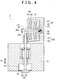
- FIGS. 4 and 5 are cross-sectional views illustrating the operation of the electromagnetically driven valve according to the first example embodiment, with FIG. 4 being a cross-sectional view showing the valve in the neutral position and FIG. 5 being a cross-sectional view showing the valve in the open position. Also, FIG. 1 is a cross-sectional view showing the valve in the closed position. Operation of the electromagnetically driven valve according to the first example embodiment will be described with reference to FIGS. 1 to 5. First, when the valve is closed, as shown in FIG.
- valve closed a predetermined electric current is run through the valve opening coil 162 and the valve closing coil 62, as denoted by "valve closed” in FIG. 3.
- the distance between the valve closing coil 62 and the disc 30 is closer than the distance between the valve opening coil 162 and the disc 30 so greater force acts between the disc 30 and the valve closing coil 62.
- the disc 30 attracts the valve closing coil 62.
- the electric current flowing through the valve opening coil 162 and the valve closing coil 62 is gradually reduced. At this time, as shown in FIG. 3, the electric current is maintained larger than 0A. Because the electric current is lower than it is when the valve is in the closed position, however, the force acting between the valve closing coil 62 and the disc 30 decreases, and becomes less than the elastic force from the torsion bar 36. As a result, the disc 30 moves downward in FIG. 1 due to the elastic force (torsion force) of the torsion bar 36 to the neutral position shown in FIG. 4. When the disc 30 is in the neutral position shown in FIG. 4, the arm portion 31 of the disc 30 is between the valve opening magnet 160 and the valve closing magnet 60. Beyond the point shown in FIG.
- the arm portion 31 moves toward the valve opening magnet 160. Then the electric current increases to the "attraction current" in FIG. 3. Accordingly, the electric current flowing through the valve opening coil 162 increases so that the valve opening coil 162 drives the arm portion 31 with great force. As a result, the arm portion 31 moves downward, as shown in FIG. 5, until it reaches the "seated" point shown in FIG. 3. In this state, the valve is open and the gap between a bell portion 13, which forms the valve element, and the valve seat 42 is large. Because the torsion bar 36 is being twisted while the valve moves from the neutral position to the open position, it applies a force which counteracts movement of the arm portion 31 to the bearing portion 38. However, because the force from the valve opening coil 162 that attracts the arm portion 31 is greater than the force applied from the torsion bar, the arm portion 31 moves downward.
- the electric current running through the valve opening coil 162 and the valve closing coil 62 is greater than 0A. Increasing the electric current running through the valve opening coil 162 and the valve closing coil 62 when the disc 30 is near the neutral position shown in FIG. 4 results in the valve closing coil 62 attracting the disc 30, thus closing the valve.
- the electromagnetically driven valve 1 Repeatedly opening and closing the valve in this way makes it possible to drive the electromagnetically driven valve 1.
- the electric current is not reduced all the way to 0A when driving the valve between the closed position and the open position, which makes it possible to reduce the time that it takes for the electric current to rise to the attraction current for the next operation (either opening or closing of the valve). Accordingly, responsiveness to the electromagnetic force is improved and the voltage can be lowered.
- FIG. 6 is a cross-sectional view of the electromagnetically driven valve 1 according to a second example embodiment of the invention.
- the electromagnetically driven valve 1 according to the second example embodiment of the invention differs from the electromagnetically driven valve 1 according to the first example embodiment in that has two discs 30 (an upper disc and a lower disc). These discs 30 are connected by a stem 1012.
- the valve opening coil 162 and the valve closing coil 62 are wound in a single electromagnet 360.
- the valve opening coil 162 and the valve closing coil 62 are serially connected.
- the electromagnetically driven valve 1 according to the second example embodiment structured as described above also displays the same effects as the electromagnetically driven valve 1 according to the first example embodiment.
- This invention may also be used in the field of an electromagnetically driven valve of an internal combustion engine mounted in a vehicle, for example.
- An electromagnetically driven valve (1) has a valve stem (12); a valve element (14) which reciprocates in the direction in which the valve stem (12) extends; a disc (30) which extends from a driving end, which is operatively linked with the valve element (14), to a pivoting end (33), and pivots around the pivoting end (33); a valve opening coil (162) and a valve closing coil (62) which oscillate the disc (30); and a electric current supply portion which supplies electric current to the valve opening coil (162) and the valve closing coil (62).
- the valve opening coil (162) and the valve closing coil (62) are serially connected.
- the reduced electric current which greater than 0, runs through the valve opening coil (162) and the valve closing coil (62) when moving the disc (30) from one of the valve opening coil (162) and the valve closing coil (62) to the other.
Landscapes
- Engineering & Computer Science (AREA)
- General Engineering & Computer Science (AREA)
- Mechanical Engineering (AREA)
- Physics & Mathematics (AREA)
- Electromagnetism (AREA)
- Power Engineering (AREA)
- Valve Device For Special Equipments (AREA)
- Magnetically Actuated Valves (AREA)
Applications Claiming Priority (1)
| Application Number | Priority Date | Filing Date | Title |
|---|---|---|---|
| JP2005229603A JP2007046497A (ja) | 2005-08-08 | 2005-08-08 | 電磁駆動弁 |
Publications (2)
| Publication Number | Publication Date |
|---|---|
| EP1752692A1 true EP1752692A1 (de) | 2007-02-14 |
| EP1752692B1 EP1752692B1 (de) | 2009-01-14 |
Family
ID=37387338
Family Applications (1)
| Application Number | Title | Priority Date | Filing Date |
|---|---|---|---|
| EP06117903A Not-in-force EP1752692B1 (de) | 2005-08-08 | 2006-07-26 | Elektromagnetisch angetriebenes Ventil |
Country Status (5)
| Country | Link |
|---|---|
| US (1) | US20070029515A1 (de) |
| EP (1) | EP1752692B1 (de) |
| JP (1) | JP2007046497A (de) |
| CN (1) | CN100427727C (de) |
| DE (1) | DE602006004801D1 (de) |
Citations (4)
| Publication number | Priority date | Publication date | Assignee | Title |
|---|---|---|---|---|
| EP1036964A1 (de) * | 1997-12-08 | 2000-09-20 | Toyota Jidosha Kabushiki Kaisha | Vorrichtung zur steuerung eines elektromagnetischen ventils |
| EP1091368A1 (de) * | 1999-10-04 | 2001-04-11 | Peugeot Citroen Automobiles SA | Elektrische Betätigungsvorrichtung, insbesondere für ein Fahrzeugmotorventil |
| US6467441B2 (en) | 2000-06-23 | 2002-10-22 | Magnetti Marelli, S.P.A. | Electromagnetic actuator for the actuation of the valves of an internal combustion engine |
| EP1296024A1 (de) * | 2001-09-20 | 2003-03-26 | MAGNETI MARELLI POWERTRAIN S.p.A. | Verfahren zur Ansteuerung elektromagnetischer Aktuatoren für die Steuerung von mehreren Ventilen einer Brennkraftmaschine |
Family Cites Families (17)
| Publication number | Priority date | Publication date | Assignee | Title |
|---|---|---|---|---|
| EP0796402B1 (de) * | 1994-11-09 | 2000-05-31 | Aura Systems, Inc. | Elektromagnetisch gelenktes ventil mit gelenkter armatur |
| US5787915A (en) * | 1997-01-21 | 1998-08-04 | J. Otto Byers & Associates | Servo positioning system |
| US6039014A (en) * | 1998-06-01 | 2000-03-21 | Eaton Corporation | System and method for regenerative electromagnetic engine valve actuation |
| US6516758B1 (en) * | 1998-11-16 | 2003-02-11 | Heinz Leiber | Electromagnetic drive |
| JP3715460B2 (ja) * | 1999-03-31 | 2005-11-09 | 株式会社日立製作所 | 機関弁の電磁駆動装置 |
| IT1310488B1 (it) * | 1999-09-23 | 2002-02-18 | Magneti Marelli Spa | Attuatore elettromagnetico per il comando delle valvole di un motore ascoppio. |
| IT1310502B1 (it) * | 1999-09-30 | 2002-02-18 | Magneti Marelli Spa | Attuatore elettromagnetico di tipo perfezionato per il comando dellevalvole di un motore a scoppio. |
| EP1270926B1 (de) * | 2000-03-08 | 2007-08-01 | Hitachi, Ltd. | Elektromagnetisch betriebenes brennstoffeinspritzventil |
| DE10035759A1 (de) * | 2000-07-22 | 2002-01-31 | Daimler Chrysler Ag | Elektromagnetischer Aktuator zur Betätigung eines Gaswechselventils einer Brennkraftmaschine |
| DE10043805A1 (de) * | 2000-09-06 | 2002-03-14 | Daimler Chrysler Ag | Vorrichtung mit einem elektromagnetischen Aktuator |
| DE10053596A1 (de) * | 2000-10-28 | 2002-05-02 | Daimler Chrysler Ag | Elektromagnetischer Aktuator zur Betätigung eines Stellgliedes |
| US6532919B2 (en) * | 2000-12-08 | 2003-03-18 | Ford Global Technologies, Inc. | Permanent magnet enhanced electromagnetic valve actuator |
| DE10120401A1 (de) * | 2001-04-25 | 2002-10-31 | Daimler Chrysler Ag | Vorrichtung zur Betätigung eines Gaswechselventils |
| US20030177989A1 (en) * | 2002-02-21 | 2003-09-25 | Baker Mark S. | Electromagnetic valve actuator for an internal combustion engine |
| US20040149944A1 (en) * | 2003-01-28 | 2004-08-05 | Hopper Mark L. | Electromechanical valve actuator |
| US20050076866A1 (en) * | 2003-10-14 | 2005-04-14 | Hopper Mark L. | Electromechanical valve actuator |
| JP2006336525A (ja) * | 2005-06-01 | 2006-12-14 | Toyota Motor Corp | 電磁駆動弁 |
-
2005
- 2005-08-08 JP JP2005229603A patent/JP2007046497A/ja not_active Withdrawn
-
2006
- 2006-07-26 CN CNB2006101075778A patent/CN100427727C/zh not_active Expired - Fee Related
- 2006-07-26 DE DE602006004801T patent/DE602006004801D1/de not_active Expired - Fee Related
- 2006-07-26 EP EP06117903A patent/EP1752692B1/de not_active Not-in-force
- 2006-07-26 US US11/492,856 patent/US20070029515A1/en not_active Abandoned
Patent Citations (4)
| Publication number | Priority date | Publication date | Assignee | Title |
|---|---|---|---|---|
| EP1036964A1 (de) * | 1997-12-08 | 2000-09-20 | Toyota Jidosha Kabushiki Kaisha | Vorrichtung zur steuerung eines elektromagnetischen ventils |
| EP1091368A1 (de) * | 1999-10-04 | 2001-04-11 | Peugeot Citroen Automobiles SA | Elektrische Betätigungsvorrichtung, insbesondere für ein Fahrzeugmotorventil |
| US6467441B2 (en) | 2000-06-23 | 2002-10-22 | Magnetti Marelli, S.P.A. | Electromagnetic actuator for the actuation of the valves of an internal combustion engine |
| EP1296024A1 (de) * | 2001-09-20 | 2003-03-26 | MAGNETI MARELLI POWERTRAIN S.p.A. | Verfahren zur Ansteuerung elektromagnetischer Aktuatoren für die Steuerung von mehreren Ventilen einer Brennkraftmaschine |
Also Published As
| Publication number | Publication date |
|---|---|
| US20070029515A1 (en) | 2007-02-08 |
| JP2007046497A (ja) | 2007-02-22 |
| DE602006004801D1 (de) | 2009-03-05 |
| EP1752692B1 (de) | 2009-01-14 |
| CN100427727C (zh) | 2008-10-22 |
| CN1912358A (zh) | 2007-02-14 |
Similar Documents
| Publication | Publication Date | Title |
|---|---|---|
| EP1789659B1 (de) | Elektromagnetisch angetriebenes ventil | |
| US7353787B2 (en) | Electromagnetically driven valve | |
| US7472884B2 (en) | Control unit for electromagnetically driven valve | |
| EP1840341B1 (de) | Elektromagnetisch angetriebenes Ventil und dessen Ansteuerungsverfahren | |
| JP2006046176A (ja) | 電磁駆動弁 | |
| EP1752692B1 (de) | Elektromagnetisch angetriebenes Ventil | |
| JP2006336525A (ja) | 電磁駆動弁 | |
| US7430996B2 (en) | Electromagnetically driven valve | |
| US7387094B2 (en) | Electromagnetically driven valve | |
| JP2010506084A (ja) | 消費エネルギーモニター式電磁駆動弁と、その制御方法 | |
| US20070058321A1 (en) | Electromagnetically driven valve and control method thereof | |
| US20080042089A1 (en) | Electromagnetically Driven Valve | |
| US7418931B2 (en) | Electromagnetically driven valve | |
| US7428887B2 (en) | Electromagnetically driven valve | |
| US20070114482A1 (en) | Electromagnetically driven valve and method for driving the same | |
| JP2009228590A (ja) | 内燃機関の吸排気弁駆動システム | |
| JP2006104981A (ja) | 電磁駆動弁および内燃機関 | |
| JP2006135025A (ja) | 電磁アクチュエータ | |
| JPH1162530A (ja) | 電磁駆動弁 | |
| JPH11236980A (ja) | 弁駆動装置 | |
| US20070125974A1 (en) | Electromagnetically driven valve | |
| JP2008248845A (ja) | 電磁駆動弁 | |
| JP2007154793A (ja) | 電磁駆動弁 |
Legal Events
| Date | Code | Title | Description |
|---|---|---|---|
| PUAI | Public reference made under article 153(3) epc to a published international application that has entered the european phase |
Free format text: ORIGINAL CODE: 0009012 |
|
| 17P | Request for examination filed |
Effective date: 20060726 |
|
| AK | Designated contracting states |
Kind code of ref document: A1 Designated state(s): AT BE BG CH CY CZ DE DK EE ES FI FR GB GR HU IE IS IT LI LT LU LV MC NL PL PT RO SE SI SK TR |
|
| AX | Request for extension of the european patent |
Extension state: AL BA HR MK YU |
|
| AKX | Designation fees paid |
Designated state(s): DE FR GB |
|
| GRAP | Despatch of communication of intention to grant a patent |
Free format text: ORIGINAL CODE: EPIDOSNIGR1 |
|
| GRAS | Grant fee paid |
Free format text: ORIGINAL CODE: EPIDOSNIGR3 |
|
| GRAA | (expected) grant |
Free format text: ORIGINAL CODE: 0009210 |
|
| AK | Designated contracting states |
Kind code of ref document: B1 Designated state(s): DE FR GB |
|
| REG | Reference to a national code |
Ref country code: GB Ref legal event code: FG4D |
|
| REF | Corresponds to: |
Ref document number: 602006004801 Country of ref document: DE Date of ref document: 20090305 Kind code of ref document: P |
|
| PLBE | No opposition filed within time limit |
Free format text: ORIGINAL CODE: 0009261 |
|
| STAA | Information on the status of an ep patent application or granted ep patent |
Free format text: STATUS: NO OPPOSITION FILED WITHIN TIME LIMIT |
|
| 26N | No opposition filed |
Effective date: 20091015 |
|
| REG | Reference to a national code |
Ref country code: FR Ref legal event code: ST Effective date: 20100331 |
|
| PG25 | Lapsed in a contracting state [announced via postgrant information from national office to epo] |
Ref country code: FR Free format text: LAPSE BECAUSE OF NON-PAYMENT OF DUE FEES Effective date: 20090731 |
|
| PG25 | Lapsed in a contracting state [announced via postgrant information from national office to epo] |
Ref country code: DE Free format text: LAPSE BECAUSE OF NON-PAYMENT OF DUE FEES Effective date: 20100202 |
|
| GBPC | Gb: european patent ceased through non-payment of renewal fee |
Effective date: 20100726 |
|
| PG25 | Lapsed in a contracting state [announced via postgrant information from national office to epo] |
Ref country code: GB Free format text: LAPSE BECAUSE OF NON-PAYMENT OF DUE FEES Effective date: 20100726 |