EP1752553A2 - Method for microstructure control of ceramic thermal spray coating - Google Patents
Method for microstructure control of ceramic thermal spray coating Download PDFInfo
- Publication number
- EP1752553A2 EP1752553A2 EP06254094A EP06254094A EP1752553A2 EP 1752553 A2 EP1752553 A2 EP 1752553A2 EP 06254094 A EP06254094 A EP 06254094A EP 06254094 A EP06254094 A EP 06254094A EP 1752553 A2 EP1752553 A2 EP 1752553A2
- Authority
- EP
- European Patent Office
- Prior art keywords
- heat
- heat source
- substrates
- ceramic
- substrate
- Prior art date
- Legal status (The legal status is an assumption and is not a legal conclusion. Google has not performed a legal analysis and makes no representation as to the accuracy of the status listed.)
- Granted
Links
Images



Classifications
-
- C—CHEMISTRY; METALLURGY
- C23—COATING METALLIC MATERIAL; COATING MATERIAL WITH METALLIC MATERIAL; CHEMICAL SURFACE TREATMENT; DIFFUSION TREATMENT OF METALLIC MATERIAL; COATING BY VACUUM EVAPORATION, BY SPUTTERING, BY ION IMPLANTATION OR BY CHEMICAL VAPOUR DEPOSITION, IN GENERAL; INHIBITING CORROSION OF METALLIC MATERIAL OR INCRUSTATION IN GENERAL
- C23C—COATING METALLIC MATERIAL; COATING MATERIAL WITH METALLIC MATERIAL; SURFACE TREATMENT OF METALLIC MATERIAL BY DIFFUSION INTO THE SURFACE, BY CHEMICAL CONVERSION OR SUBSTITUTION; COATING BY VACUUM EVAPORATION, BY SPUTTERING, BY ION IMPLANTATION OR BY CHEMICAL VAPOUR DEPOSITION, IN GENERAL
- C23C4/00—Coating by spraying the coating material in the molten state, e.g. by flame, plasma or electric discharge
- C23C4/02—Pretreatment of the material to be coated, e.g. for coating on selected surface areas
-
- C—CHEMISTRY; METALLURGY
- C23—COATING METALLIC MATERIAL; COATING MATERIAL WITH METALLIC MATERIAL; CHEMICAL SURFACE TREATMENT; DIFFUSION TREATMENT OF METALLIC MATERIAL; COATING BY VACUUM EVAPORATION, BY SPUTTERING, BY ION IMPLANTATION OR BY CHEMICAL VAPOUR DEPOSITION, IN GENERAL; INHIBITING CORROSION OF METALLIC MATERIAL OR INCRUSTATION IN GENERAL
- C23C—COATING METALLIC MATERIAL; COATING MATERIAL WITH METALLIC MATERIAL; SURFACE TREATMENT OF METALLIC MATERIAL BY DIFFUSION INTO THE SURFACE, BY CHEMICAL CONVERSION OR SUBSTITUTION; COATING BY VACUUM EVAPORATION, BY SPUTTERING, BY ION IMPLANTATION OR BY CHEMICAL VAPOUR DEPOSITION, IN GENERAL
- C23C28/00—Coating for obtaining at least two superposed coatings either by methods not provided for in a single one of groups C23C2/00 - C23C26/00 or by combinations of methods provided for in subclasses C23C and C25C or C25D
- C23C28/30—Coatings combining at least one metallic layer and at least one inorganic non-metallic layer
- C23C28/32—Coatings combining at least one metallic layer and at least one inorganic non-metallic layer including at least one pure metallic layer
- C23C28/321—Coatings combining at least one metallic layer and at least one inorganic non-metallic layer including at least one pure metallic layer with at least one metal alloy layer
- C23C28/3215—Coatings combining at least one metallic layer and at least one inorganic non-metallic layer including at least one pure metallic layer with at least one metal alloy layer at least one MCrAlX layer
-
- C—CHEMISTRY; METALLURGY
- C23—COATING METALLIC MATERIAL; COATING MATERIAL WITH METALLIC MATERIAL; CHEMICAL SURFACE TREATMENT; DIFFUSION TREATMENT OF METALLIC MATERIAL; COATING BY VACUUM EVAPORATION, BY SPUTTERING, BY ION IMPLANTATION OR BY CHEMICAL VAPOUR DEPOSITION, IN GENERAL; INHIBITING CORROSION OF METALLIC MATERIAL OR INCRUSTATION IN GENERAL
- C23C—COATING METALLIC MATERIAL; COATING MATERIAL WITH METALLIC MATERIAL; SURFACE TREATMENT OF METALLIC MATERIAL BY DIFFUSION INTO THE SURFACE, BY CHEMICAL CONVERSION OR SUBSTITUTION; COATING BY VACUUM EVAPORATION, BY SPUTTERING, BY ION IMPLANTATION OR BY CHEMICAL VAPOUR DEPOSITION, IN GENERAL
- C23C28/00—Coating for obtaining at least two superposed coatings either by methods not provided for in a single one of groups C23C2/00 - C23C26/00 or by combinations of methods provided for in subclasses C23C and C25C or C25D
- C23C28/30—Coatings combining at least one metallic layer and at least one inorganic non-metallic layer
- C23C28/34—Coatings combining at least one metallic layer and at least one inorganic non-metallic layer including at least one inorganic non-metallic material layer, e.g. metal carbide, nitride, boride, silicide layer and their mixtures, enamels, phosphates and sulphates
- C23C28/345—Coatings combining at least one metallic layer and at least one inorganic non-metallic layer including at least one inorganic non-metallic material layer, e.g. metal carbide, nitride, boride, silicide layer and their mixtures, enamels, phosphates and sulphates with at least one oxide layer
-
- C—CHEMISTRY; METALLURGY
- C23—COATING METALLIC MATERIAL; COATING MATERIAL WITH METALLIC MATERIAL; CHEMICAL SURFACE TREATMENT; DIFFUSION TREATMENT OF METALLIC MATERIAL; COATING BY VACUUM EVAPORATION, BY SPUTTERING, BY ION IMPLANTATION OR BY CHEMICAL VAPOUR DEPOSITION, IN GENERAL; INHIBITING CORROSION OF METALLIC MATERIAL OR INCRUSTATION IN GENERAL
- C23C—COATING METALLIC MATERIAL; COATING MATERIAL WITH METALLIC MATERIAL; SURFACE TREATMENT OF METALLIC MATERIAL BY DIFFUSION INTO THE SURFACE, BY CHEMICAL CONVERSION OR SUBSTITUTION; COATING BY VACUUM EVAPORATION, BY SPUTTERING, BY ION IMPLANTATION OR BY CHEMICAL VAPOUR DEPOSITION, IN GENERAL
- C23C4/00—Coating by spraying the coating material in the molten state, e.g. by flame, plasma or electric discharge
- C23C4/04—Coating by spraying the coating material in the molten state, e.g. by flame, plasma or electric discharge characterised by the coating material
- C23C4/06—Metallic material
-
- C—CHEMISTRY; METALLURGY
- C23—COATING METALLIC MATERIAL; COATING MATERIAL WITH METALLIC MATERIAL; CHEMICAL SURFACE TREATMENT; DIFFUSION TREATMENT OF METALLIC MATERIAL; COATING BY VACUUM EVAPORATION, BY SPUTTERING, BY ION IMPLANTATION OR BY CHEMICAL VAPOUR DEPOSITION, IN GENERAL; INHIBITING CORROSION OF METALLIC MATERIAL OR INCRUSTATION IN GENERAL
- C23C—COATING METALLIC MATERIAL; COATING MATERIAL WITH METALLIC MATERIAL; SURFACE TREATMENT OF METALLIC MATERIAL BY DIFFUSION INTO THE SURFACE, BY CHEMICAL CONVERSION OR SUBSTITUTION; COATING BY VACUUM EVAPORATION, BY SPUTTERING, BY ION IMPLANTATION OR BY CHEMICAL VAPOUR DEPOSITION, IN GENERAL
- C23C4/00—Coating by spraying the coating material in the molten state, e.g. by flame, plasma or electric discharge
- C23C4/12—Coating by spraying the coating material in the molten state, e.g. by flame, plasma or electric discharge characterised by the method of spraying
-
- C—CHEMISTRY; METALLURGY
- C23—COATING METALLIC MATERIAL; COATING MATERIAL WITH METALLIC MATERIAL; CHEMICAL SURFACE TREATMENT; DIFFUSION TREATMENT OF METALLIC MATERIAL; COATING BY VACUUM EVAPORATION, BY SPUTTERING, BY ION IMPLANTATION OR BY CHEMICAL VAPOUR DEPOSITION, IN GENERAL; INHIBITING CORROSION OF METALLIC MATERIAL OR INCRUSTATION IN GENERAL
- C23C—COATING METALLIC MATERIAL; COATING MATERIAL WITH METALLIC MATERIAL; SURFACE TREATMENT OF METALLIC MATERIAL BY DIFFUSION INTO THE SURFACE, BY CHEMICAL CONVERSION OR SUBSTITUTION; COATING BY VACUUM EVAPORATION, BY SPUTTERING, BY ION IMPLANTATION OR BY CHEMICAL VAPOUR DEPOSITION, IN GENERAL
- C23C4/00—Coating by spraying the coating material in the molten state, e.g. by flame, plasma or electric discharge
- C23C4/12—Coating by spraying the coating material in the molten state, e.g. by flame, plasma or electric discharge characterised by the method of spraying
- C23C4/134—Plasma spraying
-
- F—MECHANICAL ENGINEERING; LIGHTING; HEATING; WEAPONS; BLASTING
- F01—MACHINES OR ENGINES IN GENERAL; ENGINE PLANTS IN GENERAL; STEAM ENGINES
- F01D—NON-POSITIVE DISPLACEMENT MACHINES OR ENGINES, e.g. STEAM TURBINES
- F01D11/00—Preventing or minimising internal leakage of working-fluid, e.g. between stages
- F01D11/08—Preventing or minimising internal leakage of working-fluid, e.g. between stages for sealing space between rotor blade tips and stator
- F01D11/12—Preventing or minimising internal leakage of working-fluid, e.g. between stages for sealing space between rotor blade tips and stator using a rubstrip, e.g. erodible. deformable or resiliently-biased part
- F01D11/122—Preventing or minimising internal leakage of working-fluid, e.g. between stages for sealing space between rotor blade tips and stator using a rubstrip, e.g. erodible. deformable or resiliently-biased part with erodable or abradable material
-
- F—MECHANICAL ENGINEERING; LIGHTING; HEATING; WEAPONS; BLASTING
- F01—MACHINES OR ENGINES IN GENERAL; ENGINE PLANTS IN GENERAL; STEAM ENGINES
- F01D—NON-POSITIVE DISPLACEMENT MACHINES OR ENGINES, e.g. STEAM TURBINES
- F01D5/00—Blades; Blade-carrying members; Heating, heat-insulating, cooling or antivibration means on the blades or the members
- F01D5/12—Blades
- F01D5/28—Selecting particular materials; Particular measures relating thereto; Measures against erosion or corrosion
- F01D5/288—Protective coatings for blades
-
- F—MECHANICAL ENGINEERING; LIGHTING; HEATING; WEAPONS; BLASTING
- F05—INDEXING SCHEMES RELATING TO ENGINES OR PUMPS IN VARIOUS SUBCLASSES OF CLASSES F01-F04
- F05D—INDEXING SCHEME FOR ASPECTS RELATING TO NON-POSITIVE-DISPLACEMENT MACHINES OR ENGINES, GAS-TURBINES OR JET-PROPULSION PLANTS
- F05D2230/00—Manufacture
- F05D2230/90—Coating; Surface treatment
-
- F—MECHANICAL ENGINEERING; LIGHTING; HEATING; WEAPONS; BLASTING
- F05—INDEXING SCHEMES RELATING TO ENGINES OR PUMPS IN VARIOUS SUBCLASSES OF CLASSES F01-F04
- F05D—INDEXING SCHEME FOR ASPECTS RELATING TO NON-POSITIVE-DISPLACEMENT MACHINES OR ENGINES, GAS-TURBINES OR JET-PROPULSION PLANTS
- F05D2240/00—Components
- F05D2240/10—Stators
- F05D2240/11—Shroud seal segments
-
- F—MECHANICAL ENGINEERING; LIGHTING; HEATING; WEAPONS; BLASTING
- F05—INDEXING SCHEMES RELATING TO ENGINES OR PUMPS IN VARIOUS SUBCLASSES OF CLASSES F01-F04
- F05D—INDEXING SCHEME FOR ASPECTS RELATING TO NON-POSITIVE-DISPLACEMENT MACHINES OR ENGINES, GAS-TURBINES OR JET-PROPULSION PLANTS
- F05D2300/00—Materials; Properties thereof
- F05D2300/20—Oxide or non-oxide ceramics
- F05D2300/21—Oxide ceramics
-
- Y—GENERAL TAGGING OF NEW TECHNOLOGICAL DEVELOPMENTS; GENERAL TAGGING OF CROSS-SECTIONAL TECHNOLOGIES SPANNING OVER SEVERAL SECTIONS OF THE IPC; TECHNICAL SUBJECTS COVERED BY FORMER USPC CROSS-REFERENCE ART COLLECTIONS [XRACs] AND DIGESTS
- Y02—TECHNOLOGIES OR APPLICATIONS FOR MITIGATION OR ADAPTATION AGAINST CLIMATE CHANGE
- Y02T—CLIMATE CHANGE MITIGATION TECHNOLOGIES RELATED TO TRANSPORTATION
- Y02T50/00—Aeronautics or air transport
- Y02T50/60—Efficient propulsion technologies, e.g. for aircraft
Definitions
- This invention relates to thermal spray coatings and, more particularly, to controlling crack formation in ceramic coatings.
- the turbine of a modern gas turbine engine is typically of an axial flow design and includes a plurality of axial flow stages.
- Each axial flow stage comprises a plurality of blades mounted radially at the periphery of a disk which is secured to a shaft.
- a plurality of duct segments surrounds the stages to limit the leakage of gas flow around the tips of the blades.
- These duct segments are located on the inner surface of a static housing or casing. The incorporation of the duct segments improves thermal efficiency because more work may be extracted from gas flowing through the stages as opposed to leaking around the blade tips.
- duct segments limit the leakage of gas flow around the blade tips, they do not completely eliminate the leakage. It has been found that even minor amounts of gas flow around the blade tips detrimentally affect turbine efficiency. Thus, gas turbine engine designers go to great lengths to devise effective sealing structures. These structures generally include a coated duct segment in combination with a blade tip coating which renders the tips resistant to wear. In operation, the tips provide sealing by cutting into the coating on the duct segment. Thereby preventing damage to blades and resulting in minimum possible tip clearances and air leakage.
- microcracks formed parallel to the substrate surface, or horizontal microcracks, cause the coating to spall off when subjected to the above mentioned operating conditions and environment.
- vertically oriented microcracks bolster the coating's strain tolerance which prolongs the coating's service life.
- the mechanism of microcrack formation in segmented ceramic coatings is thermally induced stress. Thermal gradients are induced into the coating in a cyclic manner during coating deposition. These gradients are controlled to allow coating to be applied to a surface with no open cracks, then as each thin layer is built up and subsequently cooled, surface shrinkage produces stress levels required for cracks to propagate to the surface. Reheating of the surface then closes the cracks prior to the next thin layer of coating being applied. The relative tendency of cracks to propagate through their thickness or parallel to the substrate is dependent upon the thickness of the layers that are applied before crack propagation is induced.
- Ceramic coating loss increases blade tip clearance and thus is detrimental to turbine efficiency, as well as detrimental to the blades themselves. For example, the blades may become damaged due to the increased temperature at which the engine must then operate to make up for lost thrust. Such performance losses may be prevented by improving the quality of the segmented ceramic coating.
- United States Patent No. 6,102,656 discloses one such method of applying a segmented ceramic coating in an effort to improve the ceramic coating. Applying ceramic coatings upon substrates is an automated process whereby the substrate is placed in a fixture that rotates about an axis or moves in a linear direction along a conveyor for example.
- a substrate 10 may move in a direction indicated by an arrow 12 in such an automated process (see FIG. 1).
- a plasma torch apparatus 14 moves in a direction opposite substrate 10 as indicated by an arrow 26 and emits a plasma plume 16.
- Plasma plume 16 is defined by a pair of solid lines that is directed towards a surface 18 of substrate 10.
- Plasma torch apparatus 14 includes a ceramic (or powdered) material feeder (not shown) that emits a quantity of ceramic material 20 in a direction indicated by an arrow 28 into plasma plume 16. Ceramic material 20 becomes entrained within plasma plume 16 and is carried towards surface 18.
- plasma plume 16 comprises a much broader spray pattern than ceramic material 20 such that a deposition area 22 forms within a heated area 24 on surface 18.
- the '656 patent relies upon a high power level and gas flow utilized in conjunction with a slow relative motion of the plasma torch to the parts (substrate 10) to produce the surface heating by the plasma and air cooling necessary to achieve vertical microcracking. These conditions represent a compromise between equipment capability, efficiency and microstructural characteristics of the ceramic coating.
- the current process may not always exert adequate active control of the thermal gradients and thermal cycling that occurs in the spray process.
- the balance between vertical crack formation and horizontal crack formation is very difficult to control and occurs very randomly.
- the heating zone 24 created by the plasma torch is larger than the deposition area 22, and extends further over the substrate in the direction where deposition has just taken place than where deposition is about to take place ,i.e., the heated area 24 extends further to the left of deposition area 22 than to the right of deposition area 22 in Figure 1. Due to this relationship between surface heating and deposition location, only a moderate driving force is present to propagate through thickness cracks.
- a method of forming a segmented ceramic spray coating on a substrate broadly comprises (1) providing one or more heat sources disposed proximate to a substrate; (2) depositing optionally a quantity of a bond coat material into a heat stream of the one or more heat sources and onto a deposition area of a surface of the substrate to form an optional bond coat layer; (3) depositing optionally a quantity of a first ceramic material into the heat stream of the one or more heat sources and onto the deposition area of the surface to form an optional first ceramic material layer upon the optional bond coat layer; (4) applying the heat stream to a preheated thermal gradient zone located in front of the deposition area of a surface of the first ceramic material layer to expand the optional first ceramic material; (5) depositing one or more quantities of additional ceramic material into the heat stream upon the pre-heated, expanded optional first ceramic material layer to form one or more additional layers of ceramic material; (6) cooling one or more additional layers of ceramic materials to promote vertical crack propagation; and (7) applying the heat stream to the pre-heated
- an apparatus for applying segmented ceramic coatings broadly comprises means for supporting and moving one or more substrates; one or more heat sources disposed proximate to the one or more substrates, wherein at least one of the heat sources is positioned to apply a heat stream to pre-heat a thermal gradient zone on a surface of a substrate; a material deposition device disposed proximate to the one or more heat sources, wherein the material deposition device is positioned to deposit a material on a deposition area located behind the thermal gradient zone on the surface; and means for monitoring a surface temperature of one or more substrates.
- the methods described herein propose to increase the amount of vertical microcracking present within the coating microstructure.
- Vertical microcracking provides strain tolerance, which prolongs the coating's service life.
- the terms “equilibrium”, “equilibrate” and their related forms are intended to convey the establishment of temperatures and thermal gradients between the substrate surface and successive coating layers being deposited thereupon in order to promote vertical crack propagation in the coating.
- a repeated cycle of heat flux occurs within the coating layer(s) for a short duration of time, dynamically heating the coating layer surface and causing thermal gradients due to the heat capacities and conductivities of the materials.
- the thermal gradients are allowed to dissipate over a period of time, for example, as little as a fraction of a second, which causes shrinkage of the deposited coating layers and ratchets the vertical cracks towards the surface of the coating layers.
- the cycle of heat flux repeats over and over again as successive coatings layers are deposited.
- thermal gradients can be set up to control cracking characteristics. Unlike the process of the prior art illustrated in FIG. 1, these gradients are imposed by momentary heating of the coating surface just prior to and/or during each pass of one or more spray torches, or other heat sources, over the substrate during the deposition event.
- the thermal gradient causes expansion of the coating surface relative to the substrate, which closes the cracks while ceramic deposition is taking place. After each layer of coating is deposited the gradient is allowed to dissipate, the surface contracts and goes into tension causing propagation of the cracks to the surface.
- the surface heating, coating, cooling, and crack propagation cycles are repeated until the desired coating thickness is achieved. Benefits of this type of control include improved repeatability of microstructure formation and resultant properties, and independent control of cracking and porosity.
- the coating system described herein generally comprises a bond coat layer 30 deposited upon a surface 32 of a substrate 34, and one or more successively applied ceramic coating layers 36, 38 deposited upon bond coat layer 30.
- substrate 34 Prior to deposition, substrate 34 may be cleaned to remove contaminants using any one of or a combination of conventional methods as is understood by one of ordinary skill in the art. For example, aluminum oxide grit blasting may be utilized to clean substrate 34.
- a heat source 42 may apply heat to at least a portion of surface 32 disposed ahead of the portion of surface 32 that is being coated by a thermal spray deposition device 44. Heat source 42 raises the temperature of surface 32, or surface 32 and a deposited layer of coating, e.g., layers 30, 36, 38, prior to depositing a layer of coating thereon to ensure adequate thermal cycling and cause vertical crack propagation in the coating.
- the coating system of FIG. 2 may comprise several areas that serve to illustrate thermal gradients and crack propagation described herein.
- a low thermal gradient area 50 may initially be present where vertical cracks have propagated to the surface of the deposited layer(s).
- heat source 42 elevates the surface temperature of low thermal gradient area 50 to form surface heating area 52.
- the elevated temperature induces a thermal gradient causing the surface to expand and close existing cracks therein.
- Substrate 34 continues moving and surface heating area 52 becomes exposed to thermal spray deposition device 44.
- Device 44 deposits another successive layer 38 of coating material, within coating deposition area 54, upon existing layers 30, 36 and/or surface 32.
- the fresh coating material 38 covers the expanded surface previously described as surface heating area 52.
- the successively applied coating layers 30, 36, 38 begin cooling to form a surface cooling area 56.
- Vertical cracks begin propagating to the surface that is exposed to atmosphere to relieve tensile stresses as the temperatures between the newly deposited coating layer 38 and existing coating layers 30, 36 equilibrates.
- Substrate 34 continues moving while layer 38 continues cooling to form a low thermal gradient area 58 where vertical cracks propagate to the surface that is exposed to the atmosphere through layers 30, 36 and/or 38.
- a bond coat 30 of a MCrAlY material or other suitable material may be applied to the substrate 34.
- MCrAlY refers to known metal coating systems in which M denotes nickel, cobalt, iron, or mixtures thereof; Cr denotes chromium; Al denotes aluminum; and Y denotes yttrium.
- MCrAlY materials are often known as overlay coatings because they are applied in a predetermined composition and do not interact significantly with the substrate during the deposition process. For some non-limiting examples of MCrAlY materials see U.S. Pat. No. 3,528,861 which describes a FeCrAlY coating as does U.S. Pat. No. 3,542,530 . In addition, U.S. Pat.
- No. 3,649,225 describes a composite coating in which a layer of chromium is applied to a substrate prior to the deposition of a MCrAlY coating.
- U.S. Pat. No. 3,676,085 describes a CoCrAlY overlay coating while U.S. Pat. No. 3,754,903 describes a NiCoCrAlY overlay coating having particularly high ductility.
- U.S. Pat. No. 4,078,922 describes a cobalt base structural alloy which derives improved oxidation resistance by virtue of the presence of a combination of hafnium and yttrium.
- a preferred MCrAlY bond coat composition is described in U.S. Pat. No. Re.
- This MCrAlY bond coat 30 may be applied by any method capable of producing a dense, uniform, adherent coating of desired composition. Such techniques may include, but are not limited to, sputtering, electron beam physical vapor deposition, high velocity plasma spray techniques (HVOF, HVAF), combustion processes, wire spray techniques, laser beam cladding, electron beam cladding, etc.
- HVOF high velocity plasma spray technique
- a spray torch may operate in a vacuum chamber at a pressure of less than about 60 torr (60 mm Hg) or in another suitable atmosphere, such as air. If a vacuum chamber is employed, the substrate may be heated to a temperature of about 1500°F (816°C) to about 1900°F (1038°C). If an air atmosphere is used, the substrate temperature may be maintained at less than about 600°F (316°C).
- the particle size for the bond coat 30 may be of any suitable size, and in preferred embodiments may be between about 15 microns (0.015 mm) and about 60 microns (0.060 mm) with a mean particle size of about 25 microns (0.025 mm).
- the bond coat 30 may be applied to any suitable thickness, and in preferred embodiments may be about 5 mils (0.127 mm) to about 10 mils (0.254 mm) thick. In some preferred embodiments, the thickness may be about 6 mils (0.152 mm) to about 7 mils (0.178 mm) thick.
- Segmented ceramic coatings 36, 38 may be applied on the bond coat 30 or directly on the substrate 34.
- the ceramic coatings may comprise one or more ceramic layers 36, 38 which are individually applied to any suitable thickness. Some preferred embodiments may have an overall thickness of about 20 mils (0.508 mm) to about 150 mils (3.81 mm). Other preferred embodiments may have an overall thickness of about 50 mils (1.270 mm).
- the ceramic coatings may be produced in one or more continuous spray processes as described herein.
- a substrate 100 may move in a direction indicated by an arrow 112 in an automated process as is understood by one of ordinary skill in the art.
- a spray torch apparatus 114 may remain stationary and apply heat to substrate 100, or spray torch apparatus 114 may move in a direction opposite that of substrate 100 as indicated by an arrow 126.
- the spray torch apparatus 114 emits a heated gas plume 116 that may contain ionized species.
- the type of heat source utilized will determine whether the heat source moves or remains in place relative to the motion of the substrate 100.
- the heat source is preferably positioned to pre-heat a thermal gradient area located before the deposition area 132 on the surface 118 of the substrate 100 when applying the ceramic material.
- a representative torch may include, but is not limited to, an air plasma spray gun such as the 3MB® commercially available from Sulzer Metco, Inc., Westbury, New York.
- a ceramic (or powdered) material feeder injects a quantity of ceramic material 120 in a direction indicated by an arrow 128 into plasma plume 116.
- the direction of the injected ceramic material 120 is preferably the same as the movement of substrate 100 and opposite that of any movement of plasma torch apparatus 114. Ceramic material 120 becomes entrained within plasma plume 116 and is carried towards surface 118.
- Ceramic material 120 is preferably injected with a force sufficient to become entrained and carried by the latter portion or the far left half of plasma plume 116.
- the process in turn effectively exercises control over the location of the deposition of ceramic material 128 onto surface 118, for example, a ceramic material deposition area 132.
- Plasma plume 116 creates a heated area 130 when striking surface 118 that encompasses ceramic material deposition area 132 and effectively preheats surface 118 prior to the initial deposition or re-deposition of ceramic material 120.
- a monitoring device 134 may be employed to measure the temperature of surface 118 throughout the deposition process. Suitable monitoring devices include but are not limited to infra-red cameras, optical pyrometers, thermocouples, combinations comprising at least one of the foregoing devices, and the like. Monitoring device 134 may provide data concerning the substrate or coating surface temperatures to an operator, a PLC, an open loop control in combination with passive process controls, or a computer controlling the automated deposition process, etc.
- Heat sources 236 may be utilized to preheat the surface area 230 lying in front of a ceramic material deposition area 232.
- Heat sources 236 may have a power rating sufficient to emit a heat beam 238 upon a substrate surface 218, that is, heated area 230, in order to raise and equilibrate the temperature of substrate 200 and coating layers surrounding a ceramic material deposition area 232 to prevent and/or lessen thermal gradients and shrinkage.
- Heat sources 236 may be oriented at a distance and at an angle sufficient to ensure the temperatures of substrate 200 and coating layers are equilibrated prior to the initial deposition or re-deposition of ceramic material 220.
- Heat sources 236 may comprise any radiant or convective heat source known to one of ordinary skill in the art.
- a monitoring device 234 may be employed to measure the temperature of surface 218 throughout the deposition process. Suitable monitoring devices include but are not limited to infra-red cameras, optical pyrometers, thermocouples, combinations comprising at least one of the foregoing, and the like. Monitoring device 234 may provide data concerning the substrate and surface temperatures to an operator, a PLC, an open loop control in combination with passive process controls, or a computer controlling the automated deposition process as described earlier, etc.
- a substrate 300 may move in a direction indicated by an arrow 312.
- a plasma torch apparatus 314 may remain stationary or may move in a direction opposite that of substrate 300 as indicated by an arrow 326, and emit a plasma plume 316.
- a ceramic (or powdered) material feeder (not shown) injects a quantity of ceramic material 320 in a direction indicated by an arrow 328 into plasma plume 316.
- the direction of the injected ceramic material 320 is preferably the same as the movement of substrate 300 and opposite that of any movement of plasma torch apparatus 314. Ceramic material 320 becomes entrained within plasma plume 316 and is carried towards surface 318.
- a substrate 400 may move in a direction indicated by an arrow 412.
- a first plasma torch apparatus 414 may remain stationary or may move in a direction opposite that of substrate 400 as indicated by an arrow 426 and emit a plasma plume 416.
- One or more heat sources, and preferably a second plasma torch apparatus 436 may be utilized to preheat the existing coating surface area, that is, a heated area 430, lying in front of a ceramic material deposition area 432.
- a ceramic (or powdered) material feeder injects a quantity of ceramic material 420 in a direction indicated by an arrow 428 into plasma plume 416. Ceramic material 420 becomes entrained within plasma plume 416 and is carried towards surface 418.
- first and second plasma torch apparatus 414 and 436 By controlling the gas flow for both first and second plasma torch apparatus 414 and 436 the respective plasma plumes 416, 438 may be stretched out independently to achieve a high heat transfer rate to surface 418.
- second plasma torch apparatus 436 may be oriented at a distance and at an angle sufficient to ensure the temperatures of coating layers are heated, causing sufficiently high thermal gradients and expansion prior to the deposition of ceramic material 420.
- Second plasma torch apparatus 436 may be placed at a distance closer to surface 418 of substrate 400 than first plasma torch apparatus 414 so that second plasma plume 438 may preheat surface 418 and any coating layers already present.
- First plasma torch apparatus 414 and second plasma torch apparatus 436 may comprise any plasma torch known to one of ordinary skill in the art.
- One representative plasma torch may include but is not limited to an air plasma spray gun such as the 3MB® commercially available from Sulzer Metco, Inc., Westbury, New York.
- a monitoring device 434 may be employed to measure the temperature of surface 418 throughout the deposition process. Suitable monitoring devices include but are not limited to infra-red cameras, optical pyrometers, thermocouples, combinations comprising at least one of the foregoing, and the like. Monitoring device 434 may provide data concerning the coating surface temperatures to an operator, a PLC, an open loop control in combination with passive process controls, or a computer controlling the automated deposition process as described earlier, etc.
- the processing parameters of the methods contemplated herein are controlled to produce vertical segmentation (approximately perpendicular to the bond coat surface) and are specific to variables such as gun type and fixture geometry. In general, it is known that a close gun-to-part spray distance coupled with relatively high power deposition results in desirable vertical segmentation of between about 4 and about 20 microcracks per inch.
- the parameters may vary with the use of a different spray gun, substrate and/or fixture. Accordingly, the parameters set forth herein may be used as a guide for selecting other suitable parameters for different operating conditions.
- Ceramic material feed rate may be between about 15 grams/minute and about 300 grams/min, and in some preferred embodiments may be about 90 grams/min.
- Carrier gas flow such as nitrogen, may be used to maintain the powder under pressure and facilitate powder feed.
- the flow rate may be between about 5 scfh (standard cubic feet/hour) (0.14 scmh (standard cubic meters/hour)) and about 20 scfh (0.57 scmh), and in some preferred embodiments may be about 11 scfh (0.31 scmh).
- Standard conditions are herein defined as about room temperature (20°C) and about one atmosphere of pressure (101 kiloPascals).
- gun amperage may be between about 500 amps and about 900 amps, and in some preferred embodiments may be about 700 amps.
- the parameters are dependent on variables, including but not limited to, powder type, powder size and especially the type of gun being employed, the relative speeds and motions, and the method(s) of surface preheating employed.
Landscapes
- Chemical & Material Sciences (AREA)
- Engineering & Computer Science (AREA)
- Mechanical Engineering (AREA)
- Materials Engineering (AREA)
- Chemical Kinetics & Catalysis (AREA)
- Metallurgy (AREA)
- Organic Chemistry (AREA)
- Plasma & Fusion (AREA)
- Physics & Mathematics (AREA)
- Inorganic Chemistry (AREA)
- General Engineering & Computer Science (AREA)
- Coating By Spraying Or Casting (AREA)
- Turbine Rotor Nozzle Sealing (AREA)
Abstract
Description
- This invention relates to thermal spray coatings and, more particularly, to controlling crack formation in ceramic coatings.
- Modern gas turbine engines, particularly those used in aircraft, operate at high rotational speeds and high temperatures for increased performance and efficiency. The turbine of a modern gas turbine engine is typically of an axial flow design and includes a plurality of axial flow stages. Each axial flow stage comprises a plurality of blades mounted radially at the periphery of a disk which is secured to a shaft. A plurality of duct segments surrounds the stages to limit the leakage of gas flow around the tips of the blades. These duct segments are located on the inner surface of a static housing or casing. The incorporation of the duct segments improves thermal efficiency because more work may be extracted from gas flowing through the stages as opposed to leaking around the blade tips.
- Although the duct segments limit the leakage of gas flow around the blade tips, they do not completely eliminate the leakage. It has been found that even minor amounts of gas flow around the blade tips detrimentally affect turbine efficiency. Thus, gas turbine engine designers go to great lengths to devise effective sealing structures. These structures generally include a coated duct segment in combination with a blade tip coating which renders the tips resistant to wear. In operation, the tips provide sealing by cutting into the coating on the duct segment. Thereby preventing damage to blades and resulting in minimum possible tip clearances and air leakage.
- Unfortunately current duct segment coatings, which are typically ceramic, suffer from excessive material loss as a result of erosion or spalling. In general, erosion is the wearing away of coating material due to factors such as abrasion and corrosion. Erosion often results from particle impingement during engine operation. Spalling or spallation is typically caused by delamination cracking at the ceramic-metal interface resulting from thermal stress and the aggressive thermal environment. Spalling is essentially piecemeal coating loss consisting of many small coherent volumes of coating material.
- The coating losses due to erosion and spallation result in large part from microcracks present in the segment ceramic coating. Microcracks formed parallel to the substrate surface, or horizontal microcracks, cause the coating to spall off when subjected to the above mentioned operating conditions and environment. In contrast, vertically oriented microcracks bolster the coating's strain tolerance which prolongs the coating's service life. The mechanism of microcrack formation in segmented ceramic coatings is thermally induced stress. Thermal gradients are induced into the coating in a cyclic manner during coating deposition. These gradients are controlled to allow coating to be applied to a surface with no open cracks, then as each thin layer is built up and subsequently cooled, surface shrinkage produces stress levels required for cracks to propagate to the surface. Reheating of the surface then closes the cracks prior to the next thin layer of coating being applied. The relative tendency of cracks to propagate through their thickness or parallel to the substrate is dependent upon the thickness of the layers that are applied before crack propagation is induced.
- Ceramic coating loss increases blade tip clearance and thus is detrimental to turbine efficiency, as well as detrimental to the blades themselves. For example, the blades may become damaged due to the increased temperature at which the engine must then operate to make up for lost thrust. Such performance losses may be prevented by improving the quality of the segmented ceramic coating.
- Presently,
United States Patent No. 6,102,656 ('656 patent) discloses one such method of applying a segmented ceramic coating in an effort to improve the ceramic coating. Applying ceramic coatings upon substrates is an automated process whereby the substrate is placed in a fixture that rotates about an axis or moves in a linear direction along a conveyor for example. - As described in the '656 patent, a
substrate 10 may move in a direction indicated by anarrow 12 in such an automated process (see FIG. 1). Aplasma torch apparatus 14 moves in a direction oppositesubstrate 10 as indicated by anarrow 26 and emits aplasma plume 16.Plasma plume 16 is defined by a pair of solid lines that is directed towards asurface 18 ofsubstrate 10.Plasma torch apparatus 14 includes a ceramic (or powdered) material feeder (not shown) that emits a quantity ofceramic material 20 in a direction indicated by anarrow 28 intoplasma plume 16.Ceramic material 20 becomes entrained withinplasma plume 16 and is carried towardssurface 18. As illustrated,plasma plume 16 comprises a much broader spray pattern thanceramic material 20 such that adeposition area 22 forms within aheated area 24 onsurface 18. - The '656 patent relies upon a high power level and gas flow utilized in conjunction with a slow relative motion of the plasma torch to the parts (substrate 10) to produce the surface heating by the plasma and air cooling necessary to achieve vertical microcracking. These conditions represent a compromise between equipment capability, efficiency and microstructural characteristics of the ceramic coating.
- The current process may not always exert adequate active control of the thermal gradients and thermal cycling that occurs in the spray process. The balance between vertical crack formation and horizontal crack formation is very difficult to control and occurs very randomly. As depicted in FIG. 1, the
heating zone 24 created by the plasma torch is larger than thedeposition area 22, and extends further over the substrate in the direction where deposition has just taken place than where deposition is about to take place ,i.e., theheated area 24 extends further to the left ofdeposition area 22 than to the right ofdeposition area 22 in Figure 1. Due to this relationship between surface heating and deposition location, only a moderate driving force is present to propagate through thickness cracks. As a result, shrinkage occurs in more than one direction and thermal cycling causes cracks to form horizontally within the plane of the coating as well as vertically through the coating. The horizontal cracks that are parallel to the substrate do not improve the coating's strain tolerance and durability; these cracks actually cause the coating to spall off. - Consequently, there exists a need for an improved method for controlling the crack formation in segmented ceramic coatings, thereby improving process repeatability and consistency of coating performance, as well as for facilitating an independent control of cracking and porosity.
- In accordance with the present invention, a method of forming a segmented ceramic spray coating on a substrate broadly comprises (1) providing one or more heat sources disposed proximate to a substrate; (2) depositing optionally a quantity of a bond coat material into a heat stream of the one or more heat sources and onto a deposition area of a surface of the substrate to form an optional bond coat layer; (3) depositing optionally a quantity of a first ceramic material into the heat stream of the one or more heat sources and onto the deposition area of the surface to form an optional first ceramic material layer upon the optional bond coat layer; (4) applying the heat stream to a preheated thermal gradient zone located in front of the deposition area of a surface of the first ceramic material layer to expand the optional first ceramic material; (5) depositing one or more quantities of additional ceramic material into the heat stream upon the pre-heated, expanded optional first ceramic material layer to form one or more additional layers of ceramic material; (6) cooling one or more additional layers of ceramic materials to promote vertical crack propagation; and (7) applying the heat stream to the pre-heated thermal gradient zone of a surface of the one or more additional layers of ceramic material to expand the additional ceramic material. Steps 5 through 7 may be repeated one or more times, if desired.
- In accordance with the present invention, an apparatus for applying segmented ceramic coatings broadly comprises means for supporting and moving one or more substrates; one or more heat sources disposed proximate to the one or more substrates, wherein at least one of the heat sources is positioned to apply a heat stream to pre-heat a thermal gradient zone on a surface of a substrate; a material deposition device disposed proximate to the one or more heat sources, wherein the material deposition device is positioned to deposit a material on a deposition area located behind the thermal gradient zone on the surface; and means for monitoring a surface temperature of one or more substrates.
- Preferred embodiments of the invention will now be described, by way of example only, and with reference to the accompanying drawings in which:
- FIG. 1 is a representation of an existing system for applying a segmented ceramic spray coating;
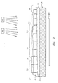
- FIG. 2 is a representation showing how to apply a segmented spray coating to achieve a vertical microcrack microstructure within the coating;
- FIG. 3 is a representation of one embodiment of a system for applying a ceramic spray coating of the present invention;
- FIG. 4 is a representation of another embodiment of a system for applying a ceramic spray coating of the present invention;
- FIG. 5 is a representation of yet another embodiment of a system for applying a ceramic spray coating of the present invention; and
- FIG. 6 is a representation of yet another embodiment of a system for applying a ceramic spray coating of the present invention.
- Like reference numbers and designations in the various drawings indicate like elements.
- To improve the quality of ceramic coatings, the methods described herein propose to increase the amount of vertical microcracking present within the coating microstructure. Vertical microcracking provides strain tolerance, which prolongs the coating's service life.
- The terms "equilibrium", "equilibrate" and their related forms are intended to convey the establishment of temperatures and thermal gradients between the substrate surface and successive coating layers being deposited thereupon in order to promote vertical crack propagation in the coating. During the processes described herein, a repeated cycle of heat flux occurs within the coating layer(s) for a short duration of time, dynamically heating the coating layer surface and causing thermal gradients due to the heat capacities and conductivities of the materials. The thermal gradients are allowed to dissipate over a period of time, for example, as little as a fraction of a second, which causes shrinkage of the deposited coating layers and ratchets the vertical cracks towards the surface of the coating layers. Throughout the methods described herein, the cycle of heat flux repeats over and over again as successive coatings layers are deposited.
- Referring now to FIG. 2, by utilizing the material properties of thermal expansion, heat capacity, and conductivity of the coating and substrate, thermal gradients can be set up to control cracking characteristics. Unlike the process of the prior art illustrated in FIG. 1, these gradients are imposed by momentary heating of the coating surface just prior to and/or during each pass of one or more spray torches, or other heat sources, over the substrate during the deposition event. The thermal gradient causes expansion of the coating surface relative to the substrate, which closes the cracks while ceramic deposition is taking place. After each layer of coating is deposited the gradient is allowed to dissipate, the surface contracts and goes into tension causing propagation of the cracks to the surface. The surface heating, coating, cooling, and crack propagation cycles are repeated until the desired coating thickness is achieved. Benefits of this type of control include improved repeatability of microstructure formation and resultant properties, and independent control of cracking and porosity.
- As illustrated in FIG. 2, the coating system described herein generally comprises a
bond coat layer 30 deposited upon asurface 32 of asubstrate 34, and one or more successively applied ceramic coating layers 36, 38 deposited uponbond coat layer 30. Prior to deposition,substrate 34 may be cleaned to remove contaminants using any one of or a combination of conventional methods as is understood by one of ordinary skill in the art. For example, aluminum oxide grit blasting may be utilized to cleansubstrate 34. Assubstrate 34 moves in a direction indicated by anarrow 40, aheat source 42 may apply heat to at least a portion ofsurface 32 disposed ahead of the portion ofsurface 32 that is being coated by a thermalspray deposition device 44. Heatsource 42 raises the temperature ofsurface 32, orsurface 32 and a deposited layer of coating, e.g., layers 30, 36, 38, prior to depositing a layer of coating thereon to ensure adequate thermal cycling and cause vertical crack propagation in the coating. - For purposes of illustration, and not to be taken in a limiting sense, the coating system of FIG. 2 may comprise several areas that serve to illustrate thermal gradients and crack propagation described herein. Prior to heating, a low
thermal gradient area 50 may initially be present where vertical cracks have propagated to the surface of the deposited layer(s). Assubstrate 34 moves,heat source 42 elevates the surface temperature of lowthermal gradient area 50 to formsurface heating area 52. Atsurface heating area 52, the elevated temperature induces a thermal gradient causing the surface to expand and close existing cracks therein.Substrate 34 continues moving andsurface heating area 52 becomes exposed to thermalspray deposition device 44.Device 44 deposits anothersuccessive layer 38 of coating material, withincoating deposition area 54, upon existinglayers surface 32. Thefresh coating material 38 covers the expanded surface previously described assurface heating area 52. - As
substrate 34 continues moving in the direction ofarrow 40 and away fromheat source 42 anddeposition device 44, the successively applied coating layers 30, 36, 38 begin cooling to form asurface cooling area 56. Vertical cracks begin propagating to the surface that is exposed to atmosphere to relieve tensile stresses as the temperatures between the newly depositedcoating layer 38 and existing coating layers 30, 36 equilibrates.Substrate 34 continues moving whilelayer 38 continues cooling to form a lowthermal gradient area 58 where vertical cracks propagate to the surface that is exposed to the atmosphere throughlayers - Optionally, a
bond coat 30 of a MCrAlY material or other suitable material may be applied to thesubstrate 34. MCrAlY refers to known metal coating systems in which M denotes nickel, cobalt, iron, or mixtures thereof; Cr denotes chromium; Al denotes aluminum; and Y denotes yttrium. MCrAlY materials are often known as overlay coatings because they are applied in a predetermined composition and do not interact significantly with the substrate during the deposition process. For some non-limiting examples of MCrAlY materials seeU.S. Pat. No. 3,528,861 which describes a FeCrAlY coating as doesU.S. Pat. No. 3,542,530 . In addition,U.S. Pat. No. 3,649,225 describes a composite coating in which a layer of chromium is applied to a substrate prior to the deposition of a MCrAlY coating.U.S. Pat. No. 3,676,085 describes a CoCrAlY overlay coating whileU.S. Pat. No. 3,754,903 describes a NiCoCrAlY overlay coating having particularly high ductility.U.S. Pat. No. 4,078,922 describes a cobalt base structural alloy which derives improved oxidation resistance by virtue of the presence of a combination of hafnium and yttrium. A preferred MCrAlY bond coat composition is described inU.S. Pat. No. Re. 32,121 , which is assigned to the present Assignee and incorporated herein by reference, as having a weight percent compositional range of 5-40 Cr, 8-35 Al, 0.1-2.0 Y, 0.1-7 Si, 0.1-2.0 Hf, balance selected from the group consisting of Ni, Co and mixtures thereof. See alsoU.S. Pat. No. 4,585,481 , which is also assigned to the present Assignee and incorporated herein by reference. - This
MCrAlY bond coat 30 may be applied by any method capable of producing a dense, uniform, adherent coating of desired composition. Such techniques may include, but are not limited to, sputtering, electron beam physical vapor deposition, high velocity plasma spray techniques (HVOF, HVAF), combustion processes, wire spray techniques, laser beam cladding, electron beam cladding, etc. In the high velocity plasma spray technique, a spray torch may operate in a vacuum chamber at a pressure of less than about 60 torr (60 mm Hg) or in another suitable atmosphere, such as air. If a vacuum chamber is employed, the substrate may be heated to a temperature of about 1500°F (816°C) to about 1900°F (1038°C). If an air atmosphere is used, the substrate temperature may be maintained at less than about 600°F (316°C). - The particle size for the
bond coat 30 may be of any suitable size, and in preferred embodiments may be between about 15 microns (0.015 mm) and about 60 microns (0.060 mm) with a mean particle size of about 25 microns (0.025 mm). Thebond coat 30 may be applied to any suitable thickness, and in preferred embodiments may be about 5 mils (0.127 mm) to about 10 mils (0.254 mm) thick. In some preferred embodiments, the thickness may be about 6 mils (0.152 mm) to about 7 mils (0.178 mm) thick. - Segmented
ceramic coatings bond coat 30 or directly on thesubstrate 34. The ceramic coatings may comprise one or moreceramic layers - Referring now to FIG. 3, a system of the present invention is illustrated. A
substrate 100 may move in a direction indicated by anarrow 112 in an automated process as is understood by one of ordinary skill in the art. Aspray torch apparatus 114 may remain stationary and apply heat tosubstrate 100, orspray torch apparatus 114 may move in a direction opposite that ofsubstrate 100 as indicated by anarrow 126. Thespray torch apparatus 114 emits aheated gas plume 116 that may contain ionized species. It is contemplated that the type of heat source utilized will determine whether the heat source moves or remains in place relative to the motion of thesubstrate 100. However, the heat source is preferably positioned to pre-heat a thermal gradient area located before thedeposition area 132 on thesurface 118 of thesubstrate 100 when applying the ceramic material. A representative torch may include, but is not limited to, an air plasma spray gun such as the 3MB® commercially available from Sulzer Metco, Inc., Westbury, New York. - Once the optional
bond coat layer 122 has been applied, a ceramic (or powdered) material feeder (not shown) injects a quantity ofceramic material 120 in a direction indicated by anarrow 128 intoplasma plume 116. The direction of the injectedceramic material 120 is preferably the same as the movement ofsubstrate 100 and opposite that of any movement ofplasma torch apparatus 114.Ceramic material 120 becomes entrained withinplasma plume 116 and is carried towardssurface 118. -
Ceramic material 120 is preferably injected with a force sufficient to become entrained and carried by the latter portion or the far left half ofplasma plume 116. By controlling the direction and velocity of the injectedceramic material 120, the process in turn effectively exercises control over the location of the deposition ofceramic material 128 ontosurface 118, for example, a ceramicmaterial deposition area 132.Plasma plume 116 creates aheated area 130 when strikingsurface 118 that encompasses ceramicmaterial deposition area 132 and effectively preheatssurface 118 prior to the initial deposition or re-deposition ofceramic material 120. - Typically, as thermal cycling occurs, deposited ceramic material begins cooling and shrinking in several directions. When another layer of ceramic material is deposited, the heat input from the ceramic material splats cause cracks within the plane of the coating. Due to the shrinkage and varying thermal gradients experienced by the coating the microcracks being formed may be non-vertical ,i.e., the microcracks may be parallel to the
surface 118 ofsubstrate 100. - Preheating
surface 118 or a deposited layer ,i.e.,bond coat layer 122, can raise and equilibrate the temperature surrounding ceramicmaterial deposition area 132 and reduce the differences in the temperature, that is, the thermal gradients, existing betweensurface 118 and/or deposited layers and ceramic material being deposited inarea 132. Shrinkage of the deposited ceramic material will become less severe relative to the pre-existing layers of ceramic, resulting in lower stresses between coating layers and a lower propensity for cracking parallel to the substrate. In addition, if the preheating occurs fast enough, a sufficient thermal gradient will be induced between thecoating surface 118 andsubstrate 100 to result in within plane stresses that will cause cracks to propagate perpendicular to the substrate upon dissipation of those gradients. The resulting deposited ceramic material layer will more likely form the desired vertically microcracked structure. - To ensure preheating occurs and thermal gradients are controlled, a
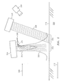
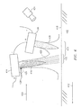
monitoring device 134 may be employed to measure the temperature ofsurface 118 throughout the deposition process. Suitable monitoring devices include but are not limited to infra-red cameras, optical pyrometers, thermocouples, combinations comprising at least one of the foregoing devices, and the like.Monitoring device 134 may provide data concerning the substrate or coating surface temperatures to an operator, a PLC, an open loop control in combination with passive process controls, or a computer controlling the automated deposition process, etc. - Referring now to FIGS. 4 and 5, two alternative embodiments of the system illustrated in FIG. 3 are depicted. Referring specifically now to FIG. 4, a
substrate 200 may move in a direction indicated by anarrow 212. Aplasma torch apparatus 214 may remain stationary or may move in a direction opposite that ofsubstrate 200 as indicated by anarrow 226, and emit aplasma plume 216. Once the optional bond coat layer has been applied, a ceramic (or powdered) material feeder (not shown) injects a quantity ofceramic material 220 in a direction indicated by anarrow 228 intoplasma plume 216. The direction of the injectedceramic material 220 is preferably the same as the movement ofsubstrate 200 and opposite that of any movement ofplasma torch apparatus 214.Ceramic material 220 becomes entrained withinplasma plume 216 and is carried towardssurface 218. - One or
more heat sources 236 may be utilized to preheat thesurface area 230 lying in front of a ceramicmaterial deposition area 232.Heat sources 236 may have a power rating sufficient to emit aheat beam 238 upon asubstrate surface 218, that is,heated area 230, in order to raise and equilibrate the temperature ofsubstrate 200 and coating layers surrounding a ceramicmaterial deposition area 232 to prevent and/or lessen thermal gradients and shrinkage.Heat sources 236 may be oriented at a distance and at an angle sufficient to ensure the temperatures ofsubstrate 200 and coating layers are equilibrated prior to the initial deposition or re-deposition ofceramic material 220.Heat sources 236 may comprise any radiant or convective heat source known to one of ordinary skill in the art. Representative heat sources may include, but are not limited to, a plasma or combustion thermal spray torch such as a 3MB® or Diamond Jet torch commercially available from Sulzer-Metco, Westbury, New York; a combustion heater or torch; radiant resistive heat sources such as incandescent, conventional or halogen lamps; laser heat sources, combinations comprising at least one of the foregoing heat sources, and the like. - As contemplated earlier, a
monitoring device 234 may be employed to measure the temperature ofsurface 218 throughout the deposition process. Suitable monitoring devices include but are not limited to infra-red cameras, optical pyrometers, thermocouples, combinations comprising at least one of the foregoing, and the like.Monitoring device 234 may provide data concerning the substrate and surface temperatures to an operator, a PLC, an open loop control in combination with passive process controls, or a computer controlling the automated deposition process as described earlier, etc. - Referring specifically now to FIG. 5, a
substrate 300 may move in a direction indicated by anarrow 312. Aplasma torch apparatus 314 may remain stationary or may move in a direction opposite that ofsubstrate 300 as indicated by anarrow 326, and emit aplasma plume 316. Once the optional bond coat layer has been applied, a ceramic (or powdered) material feeder (not shown) injects a quantity ofceramic material 320 in a direction indicated by anarrow 328 intoplasma plume 316. The direction of the injectedceramic material 320 is preferably the same as the movement ofsubstrate 300 and opposite that of any movement ofplasma torch apparatus 314.Ceramic material 320 becomes entrained withinplasma plume 316 and is carried towardssurface 318. - As described above, one or
more heat sources 336 may be utilized to preheat thesubstrate surface area 330 lying in front of a ceramicmaterial deposition area 332. In this alternative embodiment,heat source 336 may comprise a laser.Laser heat source 336 emits alaser beam 338 having a power rating or intensity sufficient to heat anarea 330 of a substrate orcoating surface 318 in order to raise the temperature of coating layers surrounding a ceramicmaterial deposition area 332 to prevent and/or lessen thermal gradients and to cause surface expansion relative to the substrate sufficient to substantially close existing through thickness cracks in the coating.Laser heat source 336 may be oriented at a distance and at an angle sufficient to ensure the temperatures of coating layers are sufficiently elevated prior to the initial deposition or re-deposition ofceramic material 320. Representative laser heat sources may include but are not limited to laser heat sources employed in welding and cutting applications as known in the art. - As contemplated earlier, a
monitoring device 334 may be employed to measure the temperature ofsurface 318 throughout the deposition process. Suitable monitoring devices include but are not limited to infra-red cameras, optical pyrometers, thermocouples, combinations comprising at least one of the foregoing, and the like.Monitoring device 334 may provide data concerning the substrate surface temperatures directly to an operator controlling the automated deposition process or provide such data to the automated system described above, etc. - Referring now to FIG. 6, yet another alternative embodiment of the system illustrated in FIG. 3 is depicted. A
substrate 400 may move in a direction indicated by anarrow 412. A firstplasma torch apparatus 414 may remain stationary or may move in a direction opposite that ofsubstrate 400 as indicated by anarrow 426 and emit aplasma plume 416. One or more heat sources, and preferably a secondplasma torch apparatus 436, may be utilized to preheat the existing coating surface area, that is, aheated area 430, lying in front of a ceramicmaterial deposition area 432. Secondplasma torch apparatus 436 emits asecond plasma plume 438 uponsurface 418, that is,heated area 430, in order to raise the temperature of coating layers surrounding a ceramicmaterial deposition area 432 to cause thermal gradients and expansion of the surface. Secondplasma torch apparatus 436 may be connected in series with first plasma torch apparatus 414 (as shown) or, in the alternative, may be powered independently and controlled by an operator, a PLC, an open loop control in combination with passive process controls, or a computer controlling the automated deposition process as described earlier.Torch apparatus Torch apparatus 436 may primarily heat the surface of the existing coating layers to expand the coating material and close the through thickness cracks on the surface. Once the optional bond coat layer has been applied, a ceramic (or powdered) material feeder (not shown) injects a quantity ofceramic material 420 in a direction indicated by anarrow 428 intoplasma plume 416.Ceramic material 420 becomes entrained withinplasma plume 416 and is carried towardssurface 418. - By controlling the gas flow for both first and second
plasma torch apparatus respective plasma plumes plasma torch apparatus 436 may be oriented at a distance and at an angle sufficient to ensure the temperatures of coating layers are heated, causing sufficiently high thermal gradients and expansion prior to the deposition ofceramic material 420. Secondplasma torch apparatus 436 may be placed at a distance closer to surface 418 ofsubstrate 400 than firstplasma torch apparatus 414 so thatsecond plasma plume 438 may preheatsurface 418 and any coating layers already present. Firstplasma torch apparatus 414 and secondplasma torch apparatus 436 may comprise any plasma torch known to one of ordinary skill in the art. One representative plasma torch may include but is not limited to an air plasma spray gun such as the 3MB® commercially available from Sulzer Metco, Inc., Westbury, New York. - As contemplated earlier, a
monitoring device 434 may be employed to measure the temperature ofsurface 418 throughout the deposition process. Suitable monitoring devices include but are not limited to infra-red cameras, optical pyrometers, thermocouples, combinations comprising at least one of the foregoing, and the like.Monitoring device 434 may provide data concerning the coating surface temperatures to an operator, a PLC, an open loop control in combination with passive process controls, or a computer controlling the automated deposition process as described earlier, etc. - The processing parameters of the methods contemplated herein are controlled to produce vertical segmentation (approximately perpendicular to the bond coat surface) and are specific to variables such as gun type and fixture geometry. In general, it is known that a close gun-to-part spray distance coupled with relatively high power deposition results in desirable vertical segmentation of between about 4 and about 20 microcracks per inch. One of ordinary skill in the art would appreciate that the parameters may vary with the use of a different spray gun, substrate and/or fixture. Accordingly, the parameters set forth herein may be used as a guide for selecting other suitable parameters for different operating conditions.
- In preferred embodiments, during the spray deposition of the ceramic material, a cylindrical fixture comprising a diameter of about 38 inches may rotate at a speed between about 5 revolutions per minute (rpm) and about 100 rpm, and preferably at about 25rpm. The plasma spray gun may be located in the interior of the hollow cylindrical fixture. The gun to part angle during individual part coating may be between about 60 degrees and about 120 degrees, and in some embodiments may be about 90 degrees. The gun-to-part distance may be varied from about 2 inches (0.05 m) to about 5 inches (0.13 m), and in some embodiments may be about 3.25 inches (0.083 m) during production of the ceramic layers. This close gun distance may be necessary for achieving satisfactory vertical segmentation. Gun traverse rate axially across the rotating fixture and substrates during deposition may be between about 0.05 inch/Revolution of the fixture (0.0013 meters/rev.) and about 1 in/Rev. (0.03 m/min), and in some embodiments may be about 0.2 in/Rev. (0.05 m/Rev.).
- Ceramic material feed rate may be between about 15 grams/minute and about 300 grams/min, and in some preferred embodiments may be about 90 grams/min. Carrier gas flow, such as nitrogen, may be used to maintain the powder under pressure and facilitate powder feed. The flow rate may be between about 5 scfh (standard cubic feet/hour) (0.14 scmh (standard cubic meters/hour)) and about 20 scfh (0.57 scmh), and in some preferred embodiments may be about 11 scfh (0.31 scmh). Standard conditions are herein defined as about room temperature (20°C) and about one atmosphere of pressure (101 kiloPascals). Primary gas flow, such as nitrogen gas, in the gun may be between about 60 scfh (1.70 scmh) and about 175 scfh (4.96 scmh), and in some preferred embodiments may be about 100 scfh (2.83 scmh). Similarly, secondary gas flow, such as hydrogen, in the gun may be between about 5 scfh (0.14 scmh) and about 30 scfh (0.85 scmh), and in some preferred embodiments may be about 18 scfh (0.51 scmh). Gun voltage may be between about 60 volts and about 80 volts, and in some preferred embodiments may be about 75 volts. Similarly, gun amperage may be between about 500 amps and about 900 amps, and in some preferred embodiments may be about 700 amps. In light of the process parameters described herein, one skilled in the art will appreciate that the parameters are dependent on variables, including but not limited to, powder type, powder size and especially the type of gun being employed, the relative speeds and motions, and the method(s) of surface preheating employed.
- The systems and methods of the present invention facilitate the independent control of coating deposition and crack formation. The systems and methods described herein control the thermal gradients responsible for crack formation by measuring and controlling the variables that directly influence crack formation, and may use an auxiliary heat source to permit independent control of spray and cracking variables. The independent control of both crack structure and coating porosity can be achieved by varying chemical compositions, porosity, and crack structure to achieve the desired thermal conductivity, erosion resistance, abradability, density, and other related crack structure and coating characteristics.
- It is to be understood that the invention is not limited to the illustrations described and shown herein, which are deemed to be merely illustrative of the best modes of carrying out the invention, and which are susceptible to modification of form, size, arrangement of parts, and details of operation. The invention rather is intended to encompass all such modifications which are within its spirit and scope as defined by the claims.
Claims (23)
- A method of forming a segmented ceramic spray coating on a substrate, comprising:(1) providing one or more heat sources disposed proximate to a substrate;(2) depositing a quantity of a first material into a heat stream of said one or more heat sources and onto a deposition area of a surface of said substrate to form a first material layer;(3) applying said heat stream to a preheated thermal gradient zone located in front of a deposition area of a surface of said first material layer to expand said material;(4) depositing one or more quantities of ceramic material into said heat stream and upon said pre-heated layer to form one or more layers of ceramic material; and(5) cooling said one or more layers of ceramic material to promote vertical crack propagation therein.
- The method of claim 1, wherein said first material layer comprises a bond coat layer.
- The method of claim 1, wherein said first material layer comprises a first ceramic material.
- The method of claim 1, wherein said first material layer comprises a first ceramic material layer on top of a bond coat layer.
- The method of any preceding claim, wherein steps 3 through 5 are repeated one or more times.
- The method of any preceding claim, wherein applying said heat stream comprises applying said heat stream using one or more heat sources.
- The method of claim 6, wherein applying said heat stream comprises applying said heat stream using two heat sources.
- The method of any preceding claim, further comprising monitoring a temperature of said first ceramic material layer and said one or more additional layers of ceramic material.
- An apparatus for applying segmented ceramic coatings, comprising:means for supporting and moving one or more substrates;one or more heat sources disposed proximate to said one or more substrates, wherein at least one of said heat sources is positioned to apply a heat stream to pre-heat a thermal gradient zone on a surface of a substrate;a material deposition device disposed proximate to said one or more heat sources, wherein said material deposition device is positioned to deposit a material on a deposition area located behind said thermal gradient zone on said surface; andmeans for monitoring a surface temperature of said one or more substrates.
- The apparatus of claim 9, wherein said one or more heat sources comprise at least one of: a torch, a radiant heat source, a convective heat source, and a laser emitting heat source.
- The apparatus of claim 9, wherein said one or more heat sources comprise a torch and a second heat source comprising at least one of: a radiant heat source, a convective heat source, and a laser emitting heat source.
- The apparatus of claim 9, wherein said one or more heat sources comprise a first heat source comprising at least one of: a radiant heat source, a convective heat source, and a laser emitting heat source; and a second heat source comprising at least one of: a radiant heat source, a convective heat source, and a laser emitting heat source.
- The apparatus of any of claims 9 to 12, wherein said material deposition device comprises a ceramic material deposition device.
- The apparatus of any of claims 9 to 12, wherein said material deposition device comprises a bond coat material deposition device.
- The apparatus of any of claims 9 to 12, wherein said material deposition device is capable of depositing more than one type of material.
- The apparatus of claim 15, wherein said more than one type of material comprises a ceramic material and a bond coat material.
- The apparatus of any of claims 9 to 16, wherein said means for supporting and moving said one or more substrates is capable of moving said one or more substrates in a first direction and said material deposition device is designed to deposit a quantity of material onto said one or more substrates in a second direction with respect to said one or more substrates.
- The apparatus of claim 17, wherein said first direction is the same or opposite said second direction.
- The apparatus of any of claims 9 to 18, wherein said means for supporting and moving said one or more substrates is capable of moving said one or more substrates in a first direction and said one or more heat sources are capable of moving in a third direction with respect to said one or more substrates.
- The apparatus of claim 19, wherein said third direction is opposite said first direction.
- The apparatus of any of claims 9 to 20, wherein said material deposition device is designed to deposit a quantity of material onto said one or more substrates in a second direction and said one or more heat sources are capable of moving in a third direction with respect to said material deposition device.
- The apparatus of claim 21, wherein said second direction is the same or opposite said third direction.
- The apparatus of any of claims 9 to 22, wherein said monitoring device comprises at least one of: an infrared camera, an optical pyrometer, and a thermocouple.
Priority Applications (1)
| Application Number | Priority Date | Filing Date | Title |
|---|---|---|---|
| EP10006996.2A EP2233599B1 (en) | 2005-08-04 | 2006-08-04 | Method for microstructure control of ceramic thermally sprayed coatings |
Applications Claiming Priority (1)
| Application Number | Priority Date | Filing Date | Title |
|---|---|---|---|
| US11/197,853 US20080166489A1 (en) | 2005-08-04 | 2005-08-04 | Method for microstructure control of ceramic thermal spray coating |
Related Child Applications (2)
| Application Number | Title | Priority Date | Filing Date |
|---|---|---|---|
| EP10006996.2A Division-Into EP2233599B1 (en) | 2005-08-04 | 2006-08-04 | Method for microstructure control of ceramic thermally sprayed coatings |
| EP10006996.2A Division EP2233599B1 (en) | 2005-08-04 | 2006-08-04 | Method for microstructure control of ceramic thermally sprayed coatings |
Publications (3)
| Publication Number | Publication Date |
|---|---|
| EP1752553A2 true EP1752553A2 (en) | 2007-02-14 |
| EP1752553A3 EP1752553A3 (en) | 2009-12-16 |
| EP1752553B1 EP1752553B1 (en) | 2014-06-04 |
Family
ID=37106924
Family Applications (2)
| Application Number | Title | Priority Date | Filing Date |
|---|---|---|---|
| EP06254094.3A Ceased EP1752553B1 (en) | 2005-08-04 | 2006-08-04 | Method for microstructure control of ceramic thermal spray coating |
| EP10006996.2A Ceased EP2233599B1 (en) | 2005-08-04 | 2006-08-04 | Method for microstructure control of ceramic thermally sprayed coatings |
Family Applications After (1)
| Application Number | Title | Priority Date | Filing Date |
|---|---|---|---|
| EP10006996.2A Ceased EP2233599B1 (en) | 2005-08-04 | 2006-08-04 | Method for microstructure control of ceramic thermally sprayed coatings |
Country Status (7)
| Country | Link |
|---|---|
| US (2) | US20080166489A1 (en) |
| EP (2) | EP1752553B1 (en) |
| JP (1) | JP2007039808A (en) |
| CN (1) | CN1908221A (en) |
| IL (1) | IL176623A0 (en) |
| SG (1) | SG130115A1 (en) |
| TW (1) | TW200712258A (en) |
Cited By (7)
| Publication number | Priority date | Publication date | Assignee | Title |
|---|---|---|---|---|
| US8802199B2 (en) | 2005-08-04 | 2014-08-12 | United Technologies Corporation | Method for microstructure control of ceramic thermal spray coating |
| EP1985723B1 (en) * | 2007-04-25 | 2015-03-25 | United Technologies Corporation | Method for improved ceramic coating |
| EP2984202A1 (en) * | 2013-04-12 | 2016-02-17 | Maschinenfabrik Reinhausen GmbH | Method and device for constructing a structure on a substrate |
| EP3068923A4 (en) * | 2013-11-11 | 2017-07-19 | United Technologies Corporation | Article with coated substrate |
| EP3434803A1 (en) * | 2017-07-28 | 2019-01-30 | United Technologies Corporation | Processes and tooling for temperature controlled plasma spray coating |
| US11123700B2 (en) | 2009-11-24 | 2021-09-21 | Gea Process Engineering A/S | Method of monitoring a spray dryer and a spray dryer comprising one or more infrared cameras |
| CN116751473A (en) * | 2023-06-20 | 2023-09-15 | 重庆大学 | A kind of high temperature resistant far infrared coating and its preparation method |
Families Citing this family (24)
| Publication number | Priority date | Publication date | Assignee | Title |
|---|---|---|---|---|
| US20100080982A1 (en) * | 2008-10-01 | 2010-04-01 | Caterpillar Inc. | Thermal spray coating application |
| US20100276827A1 (en) * | 2009-04-29 | 2010-11-04 | Kevin Smith | Method for Producing Nanoparticles |
| US20110086462A1 (en) * | 2009-10-08 | 2011-04-14 | Ovshinsky Stanford R | Process for Manufacturing Solar Cells including Ambient Pressure Plasma Torch Step |
| US8410946B2 (en) * | 2010-03-05 | 2013-04-02 | General Electric Company | Thermal measurement system and method for leak detection |
| US20110223317A1 (en) * | 2010-03-12 | 2011-09-15 | United Technologies Corporation | Direct thermal stabilization for coating application |
| US20110223354A1 (en) * | 2010-03-12 | 2011-09-15 | United Technologies Corporation | High pressure pre-oxidation for deposition of thermal barrier coating |
| US8350180B2 (en) * | 2010-03-12 | 2013-01-08 | United Technologies Corporation | High pressure pre-oxidation for deposition of thermal barrier coating with hood |
| US8328945B2 (en) * | 2010-03-12 | 2012-12-11 | United Technologies Corporation | Coating apparatus and method with indirect thermal stabilization |
| US9187815B2 (en) * | 2010-03-12 | 2015-11-17 | United Technologies Corporation | Thermal stabilization of coating material vapor stream |
| US8702372B2 (en) | 2010-05-03 | 2014-04-22 | Bha Altair, Llc | System and method for adjusting compressor inlet fluid temperature |
| US8337989B2 (en) | 2010-05-17 | 2012-12-25 | United Technologies Corporation | Layered thermal barrier coating with blended transition |
| US9097182B2 (en) | 2010-08-05 | 2015-08-04 | General Electric Company | Thermal control system for fault detection and mitigation within a power generation system |
| US8627643B2 (en) * | 2010-08-05 | 2014-01-14 | General Electric Company | System and method for measuring temperature within a turbine system |
| US9019108B2 (en) | 2010-08-05 | 2015-04-28 | General Electric Company | Thermal measurement system for fault detection within a power generation system |
| US11745201B2 (en) * | 2012-06-11 | 2023-09-05 | General Electric Company | Spray plume position feedback for robotic motion to optimize coating quality, efficiency, and repeatability |
| FR3013360B1 (en) * | 2013-11-19 | 2015-12-04 | Snecma | INTEGRATED SINTERING PROCESS FOR MICROFILERATION AND EROSION PROTECTION OF THERMAL BARRIERS |
| CA2924476A1 (en) * | 2015-04-01 | 2016-10-01 | Rolls-Royce Corporation | Vacuum plasma sprayed coating including oxide dispersions |
| DE102015211853B3 (en) * | 2015-06-25 | 2016-06-16 | Thyssenkrupp Ag | Method for coating a surface of a metal strip and metal strip coating device |
| US10815817B2 (en) * | 2016-01-21 | 2020-10-27 | Raytheon Technologies Corporation | Heat flux measurement system |
| DE102016222872A1 (en) * | 2016-11-21 | 2018-05-24 | Siemens Aktiengesellschaft | Pre-heating of a workpiece during pre-coating by a laser |
| FR3062397B1 (en) * | 2017-01-31 | 2019-04-05 | Safran Aircraft Engines | METHOD AND INSTALLATION FOR MANUFACTURING A PIECE BY PLASMAFORMING |
| US20190078463A1 (en) | 2017-09-08 | 2019-03-14 | United Technologies Corporation | Segmented Ceramic Coatings and Methods |
| CN109609886A (en) * | 2019-01-17 | 2019-04-12 | 北京矿冶科技集团有限公司 | A kind of process improving resisting corrosion of molten zinc coating life |
| TWI901741B (en) * | 2020-08-28 | 2025-10-21 | 日商東京威力科創股份有限公司 | Method for manufacturing plasma resistant component |
Citations (9)
| Publication number | Priority date | Publication date | Assignee | Title |
|---|---|---|---|---|
| US3528861A (en) | 1968-05-23 | 1970-09-15 | United Aircraft Corp | Method for coating the superalloys |
| US3542530A (en) | 1968-05-23 | 1970-11-24 | United Aircraft Corp | Nickel or cobalt base with a coating containing iron chromium and aluminum |
| US3649225A (en) | 1969-11-17 | 1972-03-14 | United Aircraft Corp | Composite coating for the superalloys |
| US3676085A (en) | 1971-02-18 | 1972-07-11 | United Aircraft Corp | Cobalt base coating for the superalloys |
| US3754903A (en) | 1970-09-15 | 1973-08-28 | United Aircraft Corp | High temperature oxidation resistant coating alloy |
| US4078922A (en) | 1975-12-08 | 1978-03-14 | United Technologies Corporation | Oxidation resistant cobalt base alloy |
| USRE32121E (en) | 1981-08-05 | 1986-04-22 | United Technologies Corporation | Overlay coatings for superalloys |
| US4585481A (en) | 1981-08-05 | 1986-04-29 | United Technologies Corporation | Overlays coating for superalloys |
| US6102656A (en) | 1995-09-26 | 2000-08-15 | United Technologies Corporation | Segmented abradable ceramic coating |
Family Cites Families (23)
| Publication number | Priority date | Publication date | Assignee | Title |
|---|---|---|---|---|
| US4297388A (en) * | 1978-11-06 | 1981-10-27 | The Charles Stark Draper Laboratory, Inc. | Process of making permanent magnets |
| JPS5887273A (en) * | 1981-11-18 | 1983-05-25 | Hitachi Ltd | Parts having ceramic coated layer and their production |
| US4897283A (en) * | 1985-12-20 | 1990-01-30 | The Charles Stark Draper Laboratory, Inc. | Process of producing aligned permanent magnets |
| JPS62274062A (en) * | 1986-05-23 | 1987-11-28 | Toyota Motor Corp | Production of ceramic coated member |
| JPS63218272A (en) * | 1987-03-06 | 1988-09-12 | Hideo Nagasaka | Method and device for thermal spraying |
| US5073433B1 (en) * | 1989-10-20 | 1995-10-31 | Praxair Technology Inc | Thermal barrier coating for substrates and process for producing it |
| US5688564A (en) * | 1992-07-23 | 1997-11-18 | Institut Polytechnique De Sevenans | Process for the preparation and coating of a surface |
| JPH09327779A (en) * | 1996-06-07 | 1997-12-22 | Mitsubishi Heavy Ind Ltd | Method for forming crack in ceramic film, and ceramic film parts formed by the method |
| US5897921A (en) * | 1997-01-24 | 1999-04-27 | General Electric Company | Directionally solidified thermal barrier coating |
| JPH10310859A (en) * | 1997-05-09 | 1998-11-24 | Natl Space Dev Agency Japan<Nasda> | Method for treating surface of hard inorganic material |
| DE19740205B4 (en) * | 1997-09-12 | 2004-11-25 | Fraunhofer-Gesellschaft zur Förderung der angewandten Forschung e.V. | Process for applying a coating by means of plasma spraying |
| US6482476B1 (en) * | 1997-10-06 | 2002-11-19 | Shengzhong Frank Liu | Low temperature plasma enhanced CVD ceramic coating process for metal, alloy and ceramic materials |
| JP2000054105A (en) * | 1998-07-16 | 2000-02-22 | Sulzer Metoco Ag | Method for pretreatment and coating of surface |
| DE19837400C1 (en) * | 1998-08-18 | 1999-11-18 | Siemens Ag | Coating of high-temperature components by plasma spraying |
| JP2000144365A (en) * | 1998-11-05 | 2000-05-26 | Toshiba Corp | Thermal barrier coating member, method of manufacturing thermal barrier coating member, and high temperature gas turbine using thermal barrier coating member |
| JP2001329358A (en) * | 2000-05-19 | 2001-11-27 | Mitsubishi Heavy Ind Ltd | Heat-insulated member, its manufacturing method, turbine blade, and gas turbine |
| JP4166416B2 (en) * | 2000-05-26 | 2008-10-15 | 関西電力株式会社 | Method for forming heat shielding ceramic film and heat-resistant component having the film |
| JP4036387B2 (en) * | 2001-05-11 | 2008-01-23 | 日鐵溶接工業株式会社 | Laser-assisted high-speed flame spraying method and apparatus |
| JP2003160852A (en) * | 2001-11-26 | 2003-06-06 | Mitsubishi Heavy Ind Ltd | Thermal insulating coating material, manufacturing method therefor, turbine member and gas turbine |
| UA74150C2 (en) * | 2002-01-09 | 2005-11-15 | Дженерал Електрік Компані | method fOR formING thermal barrier coating (VARIANTS) and thermal barrier coating |
| FR2836619B1 (en) * | 2002-02-28 | 2004-04-16 | Snecma Services | THERMAL PROJECTION INSTRUMENT |
| JP4095556B2 (en) * | 2003-02-28 | 2008-06-04 | スネクマ・セルビス | Sprayer |
| US20080166489A1 (en) | 2005-08-04 | 2008-07-10 | United Technologies Corporation | Method for microstructure control of ceramic thermal spray coating |
-
2005
- 2005-08-04 US US11/197,853 patent/US20080166489A1/en not_active Abandoned
-
2006
- 2006-06-21 TW TW095122287A patent/TW200712258A/en unknown
- 2006-06-29 IL IL176623A patent/IL176623A0/en unknown
- 2006-07-13 JP JP2006192259A patent/JP2007039808A/en active Pending
- 2006-08-03 SG SG200605231-0A patent/SG130115A1/en unknown
- 2006-08-04 EP EP06254094.3A patent/EP1752553B1/en not_active Ceased
- 2006-08-04 EP EP10006996.2A patent/EP2233599B1/en not_active Ceased
- 2006-08-04 CN CNA2006101086984A patent/CN1908221A/en active Pending
-
2009
- 2009-12-31 US US12/650,650 patent/US8802199B2/en not_active Expired - Lifetime
Patent Citations (9)
| Publication number | Priority date | Publication date | Assignee | Title |
|---|---|---|---|---|
| US3528861A (en) | 1968-05-23 | 1970-09-15 | United Aircraft Corp | Method for coating the superalloys |
| US3542530A (en) | 1968-05-23 | 1970-11-24 | United Aircraft Corp | Nickel or cobalt base with a coating containing iron chromium and aluminum |
| US3649225A (en) | 1969-11-17 | 1972-03-14 | United Aircraft Corp | Composite coating for the superalloys |
| US3754903A (en) | 1970-09-15 | 1973-08-28 | United Aircraft Corp | High temperature oxidation resistant coating alloy |
| US3676085A (en) | 1971-02-18 | 1972-07-11 | United Aircraft Corp | Cobalt base coating for the superalloys |
| US4078922A (en) | 1975-12-08 | 1978-03-14 | United Technologies Corporation | Oxidation resistant cobalt base alloy |
| USRE32121E (en) | 1981-08-05 | 1986-04-22 | United Technologies Corporation | Overlay coatings for superalloys |
| US4585481A (en) | 1981-08-05 | 1986-04-29 | United Technologies Corporation | Overlays coating for superalloys |
| US6102656A (en) | 1995-09-26 | 2000-08-15 | United Technologies Corporation | Segmented abradable ceramic coating |
Cited By (8)
| Publication number | Priority date | Publication date | Assignee | Title |
|---|---|---|---|---|
| US8802199B2 (en) | 2005-08-04 | 2014-08-12 | United Technologies Corporation | Method for microstructure control of ceramic thermal spray coating |
| EP1985723B1 (en) * | 2007-04-25 | 2015-03-25 | United Technologies Corporation | Method for improved ceramic coating |
| US11123700B2 (en) | 2009-11-24 | 2021-09-21 | Gea Process Engineering A/S | Method of monitoring a spray dryer and a spray dryer comprising one or more infrared cameras |
| EP2984202A1 (en) * | 2013-04-12 | 2016-02-17 | Maschinenfabrik Reinhausen GmbH | Method and device for constructing a structure on a substrate |
| EP3068923A4 (en) * | 2013-11-11 | 2017-07-19 | United Technologies Corporation | Article with coated substrate |
| US10280765B2 (en) | 2013-11-11 | 2019-05-07 | United Technologies Corporation | Article with coated substrate |
| EP3434803A1 (en) * | 2017-07-28 | 2019-01-30 | United Technologies Corporation | Processes and tooling for temperature controlled plasma spray coating |
| CN116751473A (en) * | 2023-06-20 | 2023-09-15 | 重庆大学 | A kind of high temperature resistant far infrared coating and its preparation method |
Also Published As
| Publication number | Publication date |
|---|---|
| US20120189763A1 (en) | 2012-07-26 |
| US8802199B2 (en) | 2014-08-12 |
| CN1908221A (en) | 2007-02-07 |
| EP1752553A3 (en) | 2009-12-16 |
| EP1752553B1 (en) | 2014-06-04 |
| EP2233599A3 (en) | 2011-10-19 |
| IL176623A0 (en) | 2006-10-31 |
| TW200712258A (en) | 2007-04-01 |
| US20080166489A1 (en) | 2008-07-10 |
| JP2007039808A (en) | 2007-02-15 |
| SG130115A1 (en) | 2007-03-20 |
| EP2233599B1 (en) | 2017-05-03 |
| EP2233599A2 (en) | 2010-09-29 |
Similar Documents
| Publication | Publication Date | Title |
|---|---|---|
| US8802199B2 (en) | Method for microstructure control of ceramic thermal spray coating | |
| US6054184A (en) | Method for forming a multilayer thermal barrier coating | |
| US5792521A (en) | Method for forming a multilayer thermal barrier coating | |
| EP1908856B2 (en) | Segmented abradable coatings and process(es) for applying the same | |
| DeMasi-Marcin et al. | Protective coatings in the gas turbine engine | |
| EP1985723B1 (en) | Method for improved ceramic coating | |
| EP1829984B1 (en) | Process for making a high density thermal barrier coating | |
| EP1642993B1 (en) | Segmented gadolinia zirconia coatings | |
| US6180260B1 (en) | Method for modifying the surface of a thermal barrier coating, and related articles | |
| US20090162670A1 (en) | Method for applying ceramic coatings to smooth surfaces by air plasma spray techniques, and related articles | |
| EP0926254B1 (en) | Thermal coating composition | |
| WO2002034967A1 (en) | Abradable coating applied with cold spray technique | |
| JP2009108410A (en) | Alumina-based protective coating for thermal barrier coating | |
| EP2336381B1 (en) | Plasma application of thermal barrier coatings with reduced thermal conductivity on combustor hardware | |
| US20200095666A1 (en) | Abradable coating | |
| JP6608589B2 (en) | Method for forming and forming cooling channels and related products | |
| Chen et al. | Deposition, microstructure and thermal cycling performance of strain-tolerant thermal barrier coatings | |
| EP1008669A1 (en) | Apparatus for electron beam physical vapor deposition | |
| KR20070016943A (en) | Microstructure Control Method of Ceramic Thermal Spray Coating | |
| US20070087210A1 (en) | High temperature insulative coating (XTR) | |
| US20050026001A1 (en) | Shielded ceramic thermal spray coating | |
| EP2423347A1 (en) | Method for forming a thermal barrier coating and a turbine component with the thermal barrier coating | |
| Yunus et al. | Characterization of Thermally Sprayed Coated GT Components Made of 3D Printing Based Selective Laser Melting Processed Inconel Alloy 718 |
Legal Events
| Date | Code | Title | Description |
|---|---|---|---|
| PUAI | Public reference made under article 153(3) epc to a published international application that has entered the european phase |
Free format text: ORIGINAL CODE: 0009012 |
|
| AK | Designated contracting states |
Kind code of ref document: A2 Designated state(s): AT BE BG CH CY CZ DE DK EE ES FI FR GB GR HU IE IS IT LI LT LU LV MC NL PL PT RO SE SI SK TR |
|
| AX | Request for extension of the european patent |
Extension state: AL BA HR MK YU |
|
| PUAL | Search report despatched |
Free format text: ORIGINAL CODE: 0009013 |
|
| AK | Designated contracting states |
Kind code of ref document: A3 Designated state(s): AT BE BG CH CY CZ DE DK EE ES FI FR GB GR HU IE IS IT LI LT LU LV MC NL PL PT RO SE SI SK TR |
|
| AX | Request for extension of the european patent |
Extension state: AL BA HR MK RS |
|
| 17P | Request for examination filed |
Effective date: 20100331 |
|
| AKX | Designation fees paid |
Designated state(s): DE GB |
|
| 17Q | First examination report despatched |
Effective date: 20111018 |
|
| REG | Reference to a national code |
Ref country code: DE Ref legal event code: R079 Ref document number: 602006041767 Country of ref document: DE Free format text: PREVIOUS MAIN CLASS: C23C0004020000 Ipc: C23C0004120000 |
|
| RIC1 | Information provided on ipc code assigned before grant |
Ipc: C23C 4/12 20060101AFI20121211BHEP Ipc: F01D 5/28 20060101ALI20121211BHEP Ipc: C23C 4/02 20060101ALI20121211BHEP Ipc: F01D 11/12 20060101ALI20121211BHEP Ipc: C23C 4/06 20060101ALI20121211BHEP Ipc: C23C 28/00 20060101ALI20121211BHEP |
|
| GRAP | Despatch of communication of intention to grant a patent |
Free format text: ORIGINAL CODE: EPIDOSNIGR1 |
|
| INTG | Intention to grant announced |
Effective date: 20131219 |
|
| GRAS | Grant fee paid |
Free format text: ORIGINAL CODE: EPIDOSNIGR3 |
|
| GRAA | (expected) grant |
Free format text: ORIGINAL CODE: 0009210 |
|
| AK | Designated contracting states |
Kind code of ref document: B1 Designated state(s): DE GB |
|
| REG | Reference to a national code |
Ref country code: GB Ref legal event code: FG4D Ref country code: DE Ref legal event code: R081 Ref document number: 602006041767 Country of ref document: DE Owner name: UNITED TECHNOLOGIES CORP. (N.D.GES.D. STAATES , US Free format text: FORMER OWNER: UNITED TECHNOLOGIES CORP. (N.D.GES.D. STAATES DELAWARE), HARTFORD, CONN., US |
|
| REG | Reference to a national code |
Ref country code: DE Ref legal event code: R096 Ref document number: 602006041767 Country of ref document: DE Effective date: 20140710 |
|
| REG | Reference to a national code |
Ref country code: DE Ref legal event code: R097 Ref document number: 602006041767 Country of ref document: DE |
|
| PLBE | No opposition filed within time limit |
Free format text: ORIGINAL CODE: 0009261 |
|
| STAA | Information on the status of an ep patent application or granted ep patent |
Free format text: STATUS: NO OPPOSITION FILED WITHIN TIME LIMIT |
|
| 26N | No opposition filed |
Effective date: 20150305 |
|
| REG | Reference to a national code |
Ref country code: DE Ref legal event code: R097 Ref document number: 602006041767 Country of ref document: DE Effective date: 20150305 |
|
| REG | Reference to a national code |
Ref country code: DE Ref legal event code: R082 Ref document number: 602006041767 Country of ref document: DE Representative=s name: SCHMITT-NILSON SCHRAUD WAIBEL WOHLFROM PATENTA, DE |
|
| REG | Reference to a national code |
Ref country code: DE Ref legal event code: R082 Ref document number: 602006041767 Country of ref document: DE Representative=s name: SCHMITT-NILSON SCHRAUD WAIBEL WOHLFROM PATENTA, DE Ref country code: DE Ref legal event code: R081 Ref document number: 602006041767 Country of ref document: DE Owner name: UNITED TECHNOLOGIES CORP. (N.D.GES.D. STAATES , US Free format text: FORMER OWNER: UNITED TECHNOLOGIES CORP., HARTFORD, CONN., US |
|
| PGFP | Annual fee paid to national office [announced via postgrant information from national office to epo] |
Ref country code: DE Payment date: 20190722 Year of fee payment: 14 |
|
| REG | Reference to a national code |
Ref country code: DE Ref legal event code: R119 Ref document number: 602006041767 Country of ref document: DE |
|
| PG25 | Lapsed in a contracting state [announced via postgrant information from national office to epo] |
Ref country code: DE Free format text: LAPSE BECAUSE OF NON-PAYMENT OF DUE FEES Effective date: 20210302 |
|
| PGFP | Annual fee paid to national office [announced via postgrant information from national office to epo] |
Ref country code: GB Payment date: 20230720 Year of fee payment: 18 |
|
| GBPC | Gb: european patent ceased through non-payment of renewal fee |
Effective date: 20240804 |
|
| PG25 | Lapsed in a contracting state [announced via postgrant information from national office to epo] |
Ref country code: GB Free format text: LAPSE BECAUSE OF NON-PAYMENT OF DUE FEES Effective date: 20240804 |