EP1752301B1 - Farbbandkassette - Google Patents
Farbbandkassette Download PDFInfo
- Publication number
- EP1752301B1 EP1752301B1 EP06252826A EP06252826A EP1752301B1 EP 1752301 B1 EP1752301 B1 EP 1752301B1 EP 06252826 A EP06252826 A EP 06252826A EP 06252826 A EP06252826 A EP 06252826A EP 1752301 B1 EP1752301 B1 EP 1752301B1
- Authority
- EP
- European Patent Office
- Prior art keywords
- case portion
- ink sheet
- case
- hook
- pair
- Prior art date
- Legal status (The legal status is an assumption and is not a legal conclusion. Google has not performed a legal analysis and makes no representation as to the accuracy of the status listed.)
- Not-in-force
Links
- 230000008878 coupling Effects 0.000 claims description 99
- 238000010168 coupling process Methods 0.000 claims description 99
- 238000005859 coupling reaction Methods 0.000 claims description 99
- 238000000926 separation method Methods 0.000 description 12
- 239000000853 adhesive Substances 0.000 description 10
- 230000001070 adhesive effect Effects 0.000 description 10
- 230000002401 inhibitory effect Effects 0.000 description 5
- 238000000034 method Methods 0.000 description 5
- 239000011347 resin Substances 0.000 description 4
- 229920005989 resin Polymers 0.000 description 4
- 230000006835 compression Effects 0.000 description 2
- 238000007906 compression Methods 0.000 description 2
Images





Classifications
-
- B—PERFORMING OPERATIONS; TRANSPORTING
- B41—PRINTING; LINING MACHINES; TYPEWRITERS; STAMPS
- B41J—TYPEWRITERS; SELECTIVE PRINTING MECHANISMS, i.e. MECHANISMS PRINTING OTHERWISE THAN FROM A FORME; CORRECTION OF TYPOGRAPHICAL ERRORS
- B41J17/00—Mechanisms for manipulating page-width impression-transfer material, e.g. carbon paper
- B41J17/32—Detachable carriers or holders for impression-transfer material mechanism
Definitions
- the present invention relates to an ink sheet cartridge, and more particularly, it relates to an ink sheet cartridge mounted on a printer.
- An ink sheet cartridge mounted on a printer is known in general, as disclosed in Japanese Patent Laying-Open No. 6-183087 (1994 ) or 6-199388 (1994 ), for example.
- the aforementioned Japanese Patent Laying-Open No. 6-183087 describes an ink sheet cartridge comprising upper and lower shell halves rotatably storing a feed bobbin wound with an ink sheet and a take-up bobbin taking up a spent ink sheet respectively.
- a first end of the upper shell half is attached to a first end of the lower shell half in an openable/closable manner with a hinge, and the upper and lower shell halves are assembled with each other by engaging a hook provided on a second end of the upper shell half with an engaging hole provided on a second end of the lower shell half.
- protrusions are provided on both side ends of the upper and lower shell halves respectively.
- Separately formed holding members are fitted with the protrusions of the upper and lower shell halves assembled with each other, thereby suppressing disassembly of the upper and lower shell halves.
- the aforementioned Japanese Patent Laying-Open No. 6-199388 describes an ink sheet cartridge comprising upper and lower shell halves rotatably storing a feed bobbin wound with an ink sheet and a take-up bobbin taking up a spent ink sheet respectively.
- a separately formed cover is mounted on the ink sheet cartridge for fixing the upper and lower shell halves to each other.
- FIG. 16 is an exploded perspective view of a conventional ink sheet cartridge 100 employed for a thermal transfer printer.
- Fig. 17 is an overall perspective view of the conventional ink sheet cartridge 100 employed for a thermal transfer printer.
- Fig. 18 is a sectional view taken along the line 200-200 in Fig. 17 . The structure of the conventional ink sheet cartridge 100 employed for a thermal transfer printer is described with reference to Figs. 16 to 18 .
- the conventional ink sheet cartridge 100 employed for a thermal transfer printer comprises upper and lower components 102 and 103 of resin constituting a bobbin case 101, as shown in Fig. 16 .
- the bobbin case 101 stores a feed bobbin 105 feeding an ink sheet 104, a take-up bobbin 106 taking up the ink sheet 104 and helical compression springs 107 for urging the feed bobbin 105 and the take-up bobbin 106 toward a first end of the bobbin case 101.
- Separately formed holding members 108 of resin are attached to both outer surfaces of the bobbin case 101 for holding the upper and lower components 102 and 103 in a state fixed to each other, as shown in Figs. 16 and 17 .
- the upper component 102 constituting the bobbin case 101 includes a feed bobbin storage portion 102a storing the feed bobbin 105, a take-up bobbin storage portion 102b storing the take-up bobbin 106 and coupling portions 102c and 102d coupling the feed bobbin storage portion 102a and the take-up bobbin storage portion 102b with each other, as shown in Fig. 16 .
- Protrusions 102e extending in parallel with the extensional direction of the feed bobbin storage portion 102a and the take-up bobbin storage portion 102b are provided on both outer surfaces of the upper component 102.
- the lower component 103 constituting the bobbin case 101 includes a feed bobbin storage portion 103a storing the feed bobbin 105, a take-up bobbin storage portion 103b storing the take-up bobbin 106 and coupling portions 103c and 103d coupling the feed bobbin storage portion 103a and the take-up bobbin storage portion 103b with each other, as shown in Fig. 16 .
- the feed bobbin storage portion 103a is provided therein with a feed bobbin support portion 103e rotatably supporting the feed bobbin 105, while the take-up bobbin storage portion 103b is provided therein with a take-up bobbin support portion 103f rotatably supporting the take-up bobbin 106.
- Protrusions 103g extending in parallel with the extensional direction of the feed bobbin storage portion 103a and the take-up bobbin storage portion 103b are provided on both outer surfaces of the lower component 103.
- the feed bobbin 105 is provided with a sheet feed shaft 105a wound with the ink sheet 104, a flange 105b, a drive shaft 105d and a driven shaft 105d, as shown in Fig. 16 .
- the take-up bobbin 106 is provided with a sheet take-up shaft 106a taking up the ink sheet 104, a flange 106b, a drive shaft 106c and a driven shaft 106d, as shown in Fig. 16 .
- Each of the holding members 108 has a U-shaped section, as shown in Figs. 16 to 18 .
- FIG. 16 A method of assembling the upper and lower components 102 and 103 of the conventional ink sheet cartridge 100 employed for a thermal transfer printer is now described with reference to Figs. 16 to 18 .
- the helical compression springs 107 are set on the driven shafts 105d and 106d of the feed bobbin 105 and the take-up bobbin 106 respectively, as shown in Fig. 16 .
- the feed bobbin 105 and the take-up bobbin 106 are arranged to be supported by the feed bobbin support portion 103e and the take-up bobbin support portion 103f of the feed bobbin storage portion 103e and the take-up bobbin storage portion 103b of the lower component 103 respectively.
- an adhesive is applied to contact surfaces of the upper and lower components 102 and 103 coming into contact with each other when the upper and lower components 102 and 103 fixed to each other. More specifically, the adhesive is applied to contact surfaces of the coupling portions 102c and 102d of the upper component 102, those of the protrusions 102e provided on both side surfaces of the upper component 102, those of the coupling portions 103c and 103d of the lower component 103 and those of the protrusions 103g provided on both side surfaces of the lower component 103 respectively.
- the upper and lower components 102 and 103 are so butted to each other that the contact surfaces thereof come into contact with each other.
- the holding members 108 coated with an adhesive are fitted with the contact portions between the protrusions 102e and 103g of the upper and lower components 102 and 103, as shown in Figs. 17 and 18 .
- the upper and lower components 102 and 103 of the ink sheet cartridge 100 are fixed to and assembled with each other.
- the upper and lower components 102 and 103 are held in the fixed state by fitting the separately formed holding members 108 of resin with the protrusions 102e and 103g provided on both side surfaces of the ink sheet cartridge 100, and hence the holding members 108 are disadvantageously necessary in order to fix the upper and lower components 102 and 103 to each other.
- the number of components is disadvantageously increased.
- the upper and lower components 102 and 103 are fixed to each other with the adhesive and thereafter held in the fixed state with the holding members 108, and hence the adhesive is disadvantageously necessary.
- the separately formed holding members must be fitted with the protrusions provided on the upper and lower shell halves respectively in order to suppress disassembly of the upper and lower shell halves, and hence the number of components is disadvantageously increased.
- the separately formed cover must be attached in order to fix the upper and lower shell halves to each other, and hence the number of components is disadvantageously increased due to the provision of the cover.
- Document US-A-5 399 035 discloses an ink ribbon cassette having a lower and upper housing.
- Each housing comprises a pair of frame members constituting a window, and a pair of semi-cylindrical bobbin housing portions.
- a hook for engaging with a portion of the upper housing is formed on the upper surface of a frame member of the lower housing.
- An outer portion of a frame member of the upper housing is notched to form an engaging portion for engaging with the hook when the lower and upper housing portion are brought together.
- Document US 2002/021926 A1 discloses a thermal transfer recording apparatus, having a detachable ink film cassette with a supply reel and a take up reel, the supply reel having a first torque limiter which provides a braking force to the shaft of the supply reel, and the take up reel having a second torque limiter, wherein the supply reel and take up reel are supported in a first frame and the first and second torque limiters are supported in a second frame, detachable from the first frame, by sliding along the axial direction of the reels.
- the first frame is provided with holding members mounted to the lateral edges, and the second frame has slides disposed on its lateral edges, which are then accepted by the holding members of the second frame when the two frame portions are slid together.
- the present invention has been proposed in order to solve the aforementioned problems, and an object of the present invention is to provide an ink sheet cartridge, requiring no adhesive, capable of inhibiting the number of components from increase.
- an ink sheet cartridge as set out in claim 1.
- the first hook portion is integrally provided on the second case portion while the first hook engaging portion engaging with the first hook portion is integrally provided on the first case portion so that the number of components can be inhibited from increase despite the provision of the first hook portion and the first hook engaging portion and the first and second case portions can be fixed to each other through the first hook portion and the first hook engaging portion without employing an adhesive.
- first case portion or the second case portion is horizontally slid while the first and second case portions are deviated from each other by the prescribed distance thereby engaging the first hook portion with the first hook engaging portion and fixing the first and second case portions to each other so that no load is applied except in the sliding direction when the first or second case portion is horizontally slid, whereby the first or second case portion can be inhibited from deflection dissimilarly to a case of vertically fixing the first and second case portions to each other while deflecting either the first case portion or the second case portion.
- the feed bobbin and the take-up bobbin stored in the ink sheet cartridge are not displaced by deflection of the first or second case portion, whereby the first and second case portions can be easily fixed to each other.
- the first hook engaging portion preferably includes an engaging hole engaging with the first hook portion. According to this structure, the first and second case portions can be easily fixed to each other by engaging the first hook portion with the engaging hole of the first hook engaging portion.
- the first hook portion and the first hook engaging portion preferably engage with each other at least in the vertical direction. According to this structure, the first and second case portions can be inhibited from separation at least in the vertical direction.
- first hook portions are preferably provided on regions corresponding to a pair of ink sheet storage portions of the second case portion, and first hook engaging portions are preferably provided on regions corresponding to a pair of ink sheet storage portions of the first case portion According to this structure, the pairs of ink sheet storage portions of the first and second case portions can be inhibited from separation.
- a first coupling portion and a second coupling portion coupling the pair of ink sheet storage portions with each other are preferably provided in the vicinity of both side end surfaces of the first case portion respectively
- a third coupling portion and a fourth coupling portion coupling the pair of ink sheet storage portions with each other are preferably provided in the vicinity of both side end surfaces of the second case portion respectively
- the first coupling portion of the first case portion and the third coupling portion of the second case portion are preferably provided with a first engaging portion and a second engaging portion engaging with each other when either the first case portion or the second case portion is horizontally slid while the first case portion and the second case portion are deviated from each other by the prescribed distance.
- the first and third coupling portions can be inhibited from separation without employing an adhesive due to the engagement between the first and second engaging portions.
- the first case portion is preferably arranged on the second case portion, and the first engaging portion of the first case portion and the second engaging portion of the second case portion preferably vertically engage with each other. According to this structure, the first and third coupling portions of the first and second case portions can be inhibited from vertical separation.
- a pair of first protrusions are preferably provided in the vicinity of both ends of a side end surface of the first case portion while a pair of first fitting portions receiving the pair of first protrusions are preferably provided in the vicinity of both ends of a side end surface of the second case portion, a pair of second fitting portions are preferably provided in the vicinity of both ends of another side end surface of the first case portion while a pair of second protrusions inserted into the pair of second fitting portions are preferably provided in the vicinity of both ends of another side end surface of the second case portion, and the pair of first protrusions are preferably inserted into the pair of first fitting portions and the pair of second protrusions are preferably inserted into the pair of second fitting portions when either the first case portion or the second case portion is horizontally slid while the first case portion and the second case portion are deviated from each other by the prescribed distance.
- four corners of the first case portion and those of the second case portion are fixed to each other upon assembling
- the first case portion is preferably arranged on the second case portion, the first protrusions of the first case portion and the first fitting portions of the second case portion preferably vertically engage with each other, and the second fitting portions of the first case portion and the second protrusions of the second case portion preferably vertically engage with each other. According to this structure, the first and second case portions can be inhibited from vertical separation.
- a first coupling portion and a second coupling portion coupling the pair of ink sheet storage portions with each other are preferably provided in the vicinity of both side end surfaces of the first case portion respectively
- a third coupling portion and a fourth coupling portion coupling the pair of ink sheet storage portions with each other are preferably provided in the vicinity of both side end surfaces of the second case portion respectively
- a pair of the first hook portions are preferably provided either on a side of the first case portion closer to the second coupling portion than the first protrusions or on a side of the second case portion closer to the fourth coupling portion than the first fitting portions
- a pair of the first hook engaging portions are preferably provided either on the side of the second case portion closer to the fourth coupling portion than the first fitting portions or on the side of the first case portion closer to the second coupling portion than the first protrusions.
- second hook portions for fixing the sliding direction of the first case portion and the second case portion are preferably provided on the outer surfaces of the ink sheet storage portions of the first case portion to extend substantially in parallel with the extensional direction of the ink sheet storage portions, and second hook engaging portions engaging with the second hook portions are preferably provided on the outer surfaces of the ink sheet storage portions of the second case portion.
- the second hook portions and the second hook engaging portions so engage with each other as to inhibit the first or second case portion from movement in the sliding direction, whereby the first and second case portions can be inhibited from cancellation of the fixed state resulting from movement of the first or second case portion in the sliding direction.
- the second hook portions of the first case portion and the second hook engaging portions of the second case portion preferably engage with each other in the sliding direction. According to this structure, the first and second case portions can be easily inhibited from cancellation of the fixed state resulting from movement of the first or second case portion in the sliding direction.
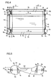
- the ink sheet cartridge 1 comprises upper and lower components 3 and 4 of resin constituting a bobbin case 2, as shown in Figs. 1 and 2 .
- the upper and lower components 3 an 4 are examples of the "first case portion" and the "second case portion” in the present invention respectively.
- the bobbin case 2 stores a feed bobbin 6 feeding an ink sheet 5, a take-up bobbin 7 taking up the ink sheet 5 and helical coil springs 8 for urging the feed bobbin 6 and the take-up bobbin 7 toward an end of the bobbin case 2, as shown in Figs. 1 and 4 .
- the upper component 3 constituting the bobbin case 2 includes a feed bobbin storage portion 3a storing the feed bobbin 6, a take-up bobbin storage portion 3b storing the take-up bobbin 7 and coupling portions 3c and 3d coupling the feed bobbin storage portion 3a and the take-up bobbin storage portion 3b with each other.
- the feed bobbin storage portion 3a and the take-up bobbin storage portion 3b are examples of the "pair of ink sheet storage portions" in the present invention.
- the coupling portions 3c and 3d are examples of the "first coupling portion" and the "second coupling portion” in the present invention respectively.
- a pair of protrusions 3e are integrally provided in the vicinity of both ends of a side end surface of the upper component 3 along arrow C, as shown in Fig. 3 .
- a pair of fitting portions 3f are integrally provided in the vicinity of both ends of another side end surface of the upper component 3 along arrow D.
- the protrusions 3e are examples of the "first protrusions” in the present invention.
- the fitting portions 3f are examples of the "second fitting portions” in the present invention.
- a pair of hook engaging portions 3g are integrally provided on the side end surface of the upper component 3 along arrow C, as shown in Fig. 3 .
- the pair of hook engaging portions 3g are provided on regions of the upper component 3 corresponding to the feed bobbin storage portion 3a and the take-up bobbin storage portion 3b respectively, as shown in Figs. 1 and 3 .
- the hook engaging portions 3g are examples of the "first hook engaging portion(s)" in the present invention.
- the pair of hook engaging portions 3g are constituted of plate members having engaging holes 3h, as shown in Fig. 1 .
- the engaging holes 3h are so formed as to engage with the forward ends of hook portions 4i described later with no clearances in the vertical direction and a sliding direction (horizontal direction) upon engagement between the hook engaging portions 3g and the hook portions 4i.
- the pair of hook engaging portions 3g are provided on positions of the upper component 3 closer to the coupling portion 3d than the protrusions 3e, as shown in Figs. 3 and 5 .
- the hook engaging portions 3g extend toward the bottom surface of the lower component 4 when the upper and lower components 3 and 4 are assembled with each other, as shown in Fig. 5 .
- an L-shaped coupling portion fixing engaging portion 3i (see Fig. 7 ) is provided on the coupling portion 3c of the upper component 3 along arrow D, as shown in Fig. 3 .
- the coupling portion fixing engaging portion 3i is an example of the "first engaging portion” in the present invention.
- Sliding direction fixing hook portions 3j are provided on both side surfaces of the end of the upper component 3 along arrow C, to extend in parallel with the extensional direction of the feed bobbin storage portion 3a and the take-up bobbin storage portion 3b.
- the sliding direction fixing hook portions 3j are examples of the "second hook portions" in the present invention.
- the lower component 4 constituting the bobbin case 2 includes a feed bobbin storage portion 4a storing a feed bobbin 6, a take-up bobbin storage portion 4b storing the take-up bobbin 7 and coupling portions 4c and 4d coupling the feed bobbin storage portion 4a and the take-up bobbin storage portion 4b with each other.
- the feed bobbin storage portion 4a and the take-up bobbin storage portion 4b are examples of the "pair of ink sheet storage portions".
- the coupling portions 4c and 4d are examples of the "third coupling portion" and the "fourth coupling portion" in the present invention respectively.
- the feed bobbin storage portion 4a is provided therein with a feed bobbin support portion 4e rotatably supporting the feed bobbin 6, while the take-up bobbin storage portion 4b is provided therein with a take-up bobbin support portion 4f rotatably supporting the take-up bobbin 7.
- a pair of fitting portions 4g are integrally provided in the vicinity of both ends of a side end surface of the lower component 4 along arrow C for receiving the pair of protrusions 3e of the upper component 3 respectively, as shown in Fig. 4 .
- the pair of fitting portions 4g and the pair of protrusions 3e vertically engage with each other.
- a pair of protrusions 4h are integrally provided in the vicinity of both ends of another side end surface of the lower component 4 along arrow D, to be inserted in to the pair of fitting portions 3f of the upper component 3 respectively.
- the pair of protrusions 4h and the pair of fitting portions 3f vertically engage with each other.
- the fitting portions 4g are examples of the "first fitting portions” in the present invention.
- the protrusions 4h are examples of the "second protrusions” in the present invention.
- a pair of hook portions 4i are integrally provided on the side end of the lower component 4 along arrow C for engaging with the pair of hook engaging portions 3g of the upper component 3.
- the pair of hook portions 4i are provided on regions of the lower component 4 corresponding to the feed bobbin storage portion 4a and the take-up bobbin storage portion 4b respectively, as shown in Figs. 1 and 4 .
- the hook portions 4i are examples of the "first hook portion” in the present invention.
- the pair of hook portions 4i are provided on positions of the lower component 4 closer to the coupling portion 4d than the fitting portions 4g, as shown in Figs. 4 and 5 . Further, the hook portions 4i extend toward the upper surface of the upper component 3 when the upper and lower components 3 and 4 are assembled with each other, as shown in Fig. 5 .
- an inverted L-shaped coupling portion fixing engaging portion 4j (see Fig. 7 ) is provided on the coupling portion 4c of the lower component 4 along arrow D for vertically engaging with the L-shaped coupling portion fixing engaging portion 3i of the upper component 3, as shown in Fig. 4 .
- the coupling portion fixing engaging portion 4j is an example of the "second engaging portion” in the present invention.
- groove-shaped sliding direction fixing hook engaging portions 4k (see Fig. 8 ) are provided on both outer surfaces of the end of the lower component 4 along arrow C for engaging with the sliding direction fixing hook portions 3j of the upper component 3.
- the sliding direction fixing hook engaging portions 4k are examples of the "second hook engaging portions" in the present invention.
- the feed bobbin 6 is provided with a sheet feed shaft 6a wound with the ink sheet 5 to be fed, a flange 6b, an engaging portion 6d (see Fig. 6 ) formed closer to the drive shaft 6c with three recess portions for engaging with a bobbin driving roll of a printer (not shown) and a driven shaft 6e, as shown in Fig. 1 .
- the take-up bobbin 7 is provided with a sheet take-up shaft 7a taking up the ink sheet 5 fed from the feed bobbin 6, a flange 7b, a drive shaft 7c, an engaging portion 7d (see Fig. 6 ) formed closer to the drive shaft 7c with three recess portions for engaging with another bobbin driving roll of the printer (not shown) and a driven shaft 7e, as shown in Fig. 1 .
- the helical coil springs 8 are set on the driven shafts 6e and 7e of the feed bobbin 6 and the take-up bobbin 7 respectively, as shown in Figs. 1 and 4 .
- the feed bobbin 6 and the take-up bobbin 7 are arranged to be supported by the feed bobbin support portion 4e and the take-up bobbin support portion of the feed bobbin storage portion 4a and the take-up bobbin storage portion 4b of the lower component 4 respectively.
- the helical coil springs 8 urge the feed bobbin 6 and the take-up bobbin 7 along arrows E respectively, as shown in Fig. 4 .
- the upper component 3 is arranged on the lower component 4 in a state deviated from the lower component 4 by a prescribed distance X.
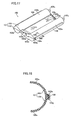
- the hook portions 4i of the lower component 4 are located under the hook engaging portions 3g of the upper component 3, as shown in Fig. 11 .
- the upper component 3 is moved along arrow F in Fig. 10 , and superposed on the lower component 4 as shown in Fig. 12 .
- the forward ends of the hook portions 4i of the lower component 4 are not yet engaged with the engaging holes 3h of the hook engaging portions 3g, constituted of plate members, of the upper component 3 but in contact with portions close to the engaging holes 3h, as shown in Figs. 12 and 13 .
- the hook portions 4i are elastically deflected, as shown in Fig. 13 .
- the upper component 3 is slid along arrow G (in the horizontal direction) in Fig. 12 with respect to the lower component 4, thereby inserting the protrusions 3e of the upper component 3 into the fitting portions 4g (see Fig. 9 ) of the lower component 4, as shown in Fig. 12 .
- the protrusions 4h of the lower component 4 are inserted into the fitting portions 3f of the upper component 3, as shown in Fig. 9 .
- the upper and lower components 3 and 4 are inhibited from vertical separation.
- the forward ends of the hook portions 4i of the lower component 4 having been in contact with the portions close to the engaging holes 3h of the hook engaging portions 3g of the upper component 3 reach the positions of the engaging holes 3h of the hook engaging portions 3g due to the sliding of the upper component 3 along arrow G (see Fig. 12 ), as shown in Fig. 14 .
- the hook portions 4i are restored from the elastically deflected state, so that the forward ends thereof engage with the engaging holes 3h of the hook engaging portions 3g as shown in Fig. 15 .
- the forward ends of the hook portions 4i engage with the engaging holes 3h of the hook engaging portions 3g with no vertical clearances, thereby inhibiting the upper and lower components 3 and 4 from vertical separation.
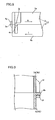
- the upper component 3 is so slid along arrow G (in the horizontal direction) in Fig. 12 with respect to the lower component 4 that the sliding direction fixing hook portions 3j of the upper component 3 engage with the sliding direction fixing hook engaging portions 4k as shown in Figs. 8 and 14 .
- the upper component 3 and the lower component 4 are inhibited from movement in the sliding direction along arrows H and I respectively, as show in Fig. 8 .
- the upper component 3 is so slid along arrow G (in the horizontal direction) in Fig. 12 with respect to the lower component 4 that the inverted L-shaped coupling portion fixing engaging portion 3i provided on the coupling portion 3c of the upper component 3 engages with the L-shaped coupling portion fixing engaging portion 4j provided on the coupling portion 4c of the lower component 4, as shown in Fig. 7 .
- the coupling portions 3c and 4c of the upper and lower components 3 and 4 are inhibited from vertical separation.
- the upper and lower components 3 and 4 of the ink sheet cartridge 1 according to this embodiment are assembled with each other in the aforementioned manner.
- the lower component 4 is integrally provided with the hook portions 4i while the upper component 3 is integrally provided with the hook engaging portions 3g engaging with the hook portions 4i in the vertical direction and the sliding direction (horizontal direction), whereby the number of components can be inhibited from increase despite the provision of the hook portions 4i and the hook engaging portions 3g and the upper and lower components 3 and 4 can be fixed to each other in the vertical direction and the sliding direction (horizontal direction) through the hook portions 4i and the hook engaging portions 3g without employing an adhesive.
- the upper component 3 is slid along arrow G (in the horizontal direction) with respect to the lower component 4 in the state deviated from the lower component 4 by the prescribed distance X thereby engaging the hook portions 4i with the hook engaging portions 3g and fixing the upper and lower components 3 and 4 to each other so that no load is applied except in the sliding direction when the upper component 3 is slid along arrow G with respect to the lower component 4, whereby the upper component 3 or the lower component 4 can be inhibited from deflection dissimilarly to a case of vertically fixing the upper and lower components 3 and 4 to each other while deflecting either the upper component 3 or the lower component 4. Therefore, the feed bobbin 6 and the take-up bobbin 7 stored in the ink sheet cartridge 1 are not displaced by deflection of the upper or lower component 3 or 4, whereby the upper and lower components 3 and 4 can be easily fixed to each other.
- the coupling portions 3c and 4c coupling the feed bobbin storage portions 3a and 4a and the take-up bobbin storage portions 3b and 4b with each other are provided in the vicinity of the side end surfaces of the upper and lower components 3 and 4 along arrow D respectively while the coupling portion fixing engaging portions 3i and 4j are provided on the coupling portions 3c and 4c of the upper and lower components 3 and 4 respectively for vertically engaging with each other when the upper component 3 is slid along arrow G (in the horizontal direction) with respect to the lower component 4 in the state deviated from the lower component 4 by the prescribed distance X, whereby the coupling portions 3c and 4c of the upper and lower components 3 an 4 can be inhibited from vertical deviation without employing an adhesive due to the engagement between the coupling portion fixing engaging portions 31 and 4j.
- the pair of protrusions 3e are provided in the vicinity of both ends of the side end surface of the upper component 3 along arrow C while the pair of fitting portions 4g vertically engaging with the pair of protrusions 3e are provided in the vicinity of both ends of the side end surface of the upper component 3 along arrow C and the pair of fitting portions 3f are provided in the vicinity of both ends of the side end surface of the upper component 3 along arrow D while the pair of protrusions 4h vertically engaging with the pair of fitting portions 3f are provided in the vicinity of both ends of the side end surface of the lower component 4 along arrow D for sliding the upper component 3 along arrow G (in the horizontal direction) with respect to the lower component 4 in the state deviated from the lower component 4 by the prescribed distance X thereby inserting the pairs of protrusions 3e and 4h into the pairs of fitting portions 4g and 3f respectively for vertically fixing four corners of the upper component 3 and those of the lower component 4 to each other upon assembling of the upper and lower components 3 and 4, whereby
- the sliding direction fixing hook portions 3j for fixing the sliding direction (horizontal direction) of the upper and lower components 3 and 4 are provided on the outer surfaces of the feed bobbin storage portion 3a and the take-up bobbin storage portion 3b of the upper component 3 to extend substantially in parallel with the extensional direction of the feed bobbin storage portion 3a and the take-up bobbin storage portion 3b of the upper component 3 while the sliding direction fixing hook engaging portions 4k engaging with the sliding direction fixing hook portions 3j are provided on the outer surfaces of the feed bobbin storage portion 4a and the take-up bobbin storage portion 4b of the lower component 4 for inhibiting the upper or lower component 3 or 4 from movement in the sliding direction due to engagement between the sliding direction fixing hook portions 3j and the sliding direction fixing hook engaging portions 4k, whereby the upper and lower components 3 and 4 can be inhibited from cancellation of the fixed state.
- the coupling portions 3d and 4d coupling the feed bobbin storage portions 3a and 4a and the take-up bobbin storage portions 3b and 4b with each other are provided in the vicinity of the side end surfaces of the upper and lower components 3 and 4 along arrow C respectively while the pair of hook engaging portions 3g constituted of the plate members having the engaging holes 3h are provided on the positions of the upper component 3 closer to the coupling portion 3d than the protrusions 3e and the pair of hook portions 4i are provided on the positions of the lower component 4 closer to the coupling portion 4d than the fitting portions 4g so that the hook portions 4i and the hook engaging portions 3g can easily engage with each other in the vicinity of the coupling portions 3d and 4d, whereby the coupling portions 3d and 4d can be inhibited from separation.
- the present invention is not restricted to this but the pair of protrusions and the pair of engaging portions may alternatively be provided only on one side end of the ink sheet cartridge for engaging with each other when either the upper component or the lower component is horizontally slid.
- the present invention is not restricted to this but the pair of hook portions may alternatively be provided in the vicinity of the coupling portions of the upper component while providing the pair of hook engaging portions in the vicinity of the coupling portions of the lower component. Further alternatively, the pair of hook portions and the pair of hook engaging portions may be provided on positions other than those in the vicinity of the coupling portions. In addition, one or at least three hook portions and one or at least three hook engaging portions may be provided for vertically fixing the upper and lower components to each other.
- the coupling portions of the upper and lower components are provided with the L-shaped and inverted L-shaped engaging portions engaging with each other in the aforementioned embodiment, the present invention is not restricted to this but the coupling portions may alternatively be provided with engaging portions having shapes other than the L and inverted L shapes.
- the present invention is not restricted to this.
Landscapes
- Impression-Transfer Materials And Handling Thereof (AREA)
Claims (18)
- Farbbandkassette, die Folgendes umfasst:ein Farbband (5) zum Drucken;einen ersten Gehäuseabschnitt (3) und einen zweiten Gehäuseabschnitt (4), die jeweils ein paar Farbbandlagerabschnitte (3a, 3b und 4a, 4b) umfassen, die das Farbband lagern;einen ersten Hakenabschnitt (4i), der einstückig an dem zweiten Gehäuseabschnitt (4) bereitgestellt ist;einen ersten Hakeneingriffsabschnitt (3g), der einstückig an dem ersten Gehäuseabschnitt (3) bereitgestellt ist, um mit dem ersten Hakenabschnitt (4i) in Eingriff zu gelangen;einen zweiten Hakenabschnitt (3j), der an dem ersten Gehäuseabschnitt (3) bereitgestellt ist;einen zweiten Hakeneingriffsabschnitt (4k), der an dem zweiten Gehäuseabschnitt (4) bereitgestellt ist;wobei der erste (3) und der zweite (4) Gehäuseabschnitt angeordnet sind, um in Bezug aufeinander in einer Verschiebungsrichtung, die als eine Richtung definiert ist, in die sich die Farbbandlagerabschnitte (3a, 3b, 4a, 4b) erstrecken, wobei sie voneinander in einem vorbestimmten Abstand in Verschiebungsrichtung abweichen, verschoben zu werden, wodurch der erste Hakenabschnitt (4i) und der erste Hakeneingriffsabschnitt (3g) in Eingriff gebracht werden und den ersten Gehäuseabschnitt und den zweiten Gehäuseabschnitt in Bezug aufeinander fixieren;wobei der zweite Hakenabschnitt (3j) und der zweite Hakeneingriffsabschnitt (4k) angeordnet sind, um zu verhindern, dass sich der erste (3) und der zweite (4) Gehäuseabschnitt in Verschiebungsrichtung bewegen, wenn der erste (3) und der zweite (4) in Bezug aufeinander fixiert werden;dadurch gekennzeichnet, dass:der erste Hakenabschnitt (4i) ablenkbar ist und der zweite Hakenabschnitt (3j) an demselben Ende des ersten Gehäuseabschnitts (3) wie der Hakeneingriffsabschnitt (3g) bereitgestellt ist und der zweite Hakeneingriffsabschnitt (4k) an demselben Ende des zweiten Gehäuseabschnitts (4) bereitgestellt ist wie der erste Hakenabschnitt (4i), wobei, wenn der erste (3) und der zweite (4) Gehäuseabschnitt in Bezug aufeinander fixiert sind, der erste Hakenabschnitt (4i) mit dem ersten Hakeneingriffsabschnitt (3g) in einem Bereich in Eingriff gelangt, der durch einen des Paars an Farbbandlagerabschnitten (3a, 3b) des ersten Gehäuseabschnitts (3) und einen des Paars an Farbbandlagerabschnitten (4a, 4b) des zweiten Gehäuseabschnitts (4) gebildet wird, der dem einen des Paars von Farbbandlagerabschnitten (3a, 3b) des ersten Gehäuseabschnitts (3) entspricht.
- Farbbandkassette nach Anspruch 1, worin der erste Hakeneingriffsabschnitt (3g) ein Eingriffsloch (3h) umfasst, das mit dem ersten Hakenabschnitt (4i) in Eingriff gelangt.
- Farbbandkassette nach Anspruch 1, worin der erste Hakenabschnitt (4i) und der erste Hakeneingriffsabschnitt (3g) mit einander in einer Richtung in Eingriff gelangen, die im rechten Winkel auf die Verschiebungsrichtung steht.
- Farbbandkassette nach Anspruch 1, worin der erste Hakenabschnitt (4i) in einem Bereich bereitgestellt ist, der einem von dem Paar an Farbbandlagerabschnitten (4a, 4b) an dem zweiten Gehäuseabschnitt (4) entspricht, und der erste Hakeneingriffsabschnitt (3g) in einem Bereich bereitgestellt ist, der einem von dem Paar an Farbbandlagerabschnitten (3a, 3b) an dem ersten Gehäuseabschnitt (3) entspricht.
- Farbbandkassette nach Anspruch 1, worin
ein erster Verbindungsabschnitt (3c) und ein zweiter Verbindungsabschnitt (3d), die das Paar an Farbbandlagerabschnitten (3a, 3b) des ersten Gehäuseabschnitts (3) miteinander verbinden, nahe des jeweiligen Endes des ersten Gehäuseabschnitts (3) bereitgestellt sind, wobei die jeweiligen Enden die Enden des ersten Gehäuseabschnitts (3) in der Richtung sind, in die sich die Farbbandlagerabschnitte (3a, 3b) des ersten Gehäuseabschnitts (3) erstrecken;
ein dritter Verbindungsabschnitt (4c) und ein Vierter Verbindungsabschnitt (4d), die das Paar an Farbbandlagerabschnitten (4a, 4b) des zweiten Gehäuseabschnitts (4) miteinander verbinden, nahe des jeweiligen Endes des zweiten Gehäuseabschnitts (4) bereitgestellt sind, wobei die jeweiligen Enden die Enden des zweiten Gehäuseabschnitts (4) in der Richtung sind, in die sich die Farbbandlagerabschnitte (4a, 4b) des zweiten Gehäuseabschnitts (4) erstrecken;
wobei der erste Verbindungsabschnitt des ersten Gehäuseabschnitts und der dritte Verbindungsabschnitt des zweiten Gehäuseabschnitts mit einem ersten Eingriffsabschnitt (3i) und einem zweiten Eingriffsabschnitt (4j) bereitgestellt sind, die miteinander in Eingriff gelangen, wenn entweder der erste Gehäuseabschnitt oder der zweite Gehäuseabschnitt in die Verschiebungsrichtung verschoben werden und über den vorgeschriebenen Abstand in der Verschiebungsrichtung voneinander abweichen. - Farbbandkassette nach Anspruch 5, worin
der erste Gehäuseabschnitt (3) auf dem zweiten Gehäuseabschnitt (4) angeordnet ist und
der erste Eingriffsabschnitt (3i) des ersten Gehäuseabschnitts (3) und der zweite Eingriffsabschnitt (4j) des zweiten Gehäuseabschnitts (4) miteinander in einer Richtung in Eingriff gelangen, die im rechten Winkel auf die Verschiebungsrichtung steht. - Farbbandkassette nach Anspruch 1, worin
ein Paar erster Vorsprünge (3e) in der Nähe beider Ränder eines Endes des ersten Gehäuseabschnitts bereitgestellt ist, wobei das Ende des ersten Gehäuseabschnitts ein Ende des ersten Gehäuseabschnitts (3) in jener Richtung ist, in die sich die Farbbandlagerabschnitte (3a, 3b) des ersten Gehäuseabschnitts (3) erstrecken, während ein Paar erster Einpassabschnitte (4g), die das Paar erster Vorsprünge (3e) aufnehmen, in der Nähe beider Ränder eines Endes des zweiten Gehäuseabschnitts (4) bereitgestellt sind, wobei das Ende des zweiten Gehäuseabschnitts ein Ende des zweiten Gehäuseabschnitts (r) in jener Richtung ist, in die sich die Farbbandlagerabschnitte (4a, 4b) des zweiten Gehäuseabschnitts (4) erstrecken,
ein Paar zweiter Einpassabschnitte (3f) in der Nähe beider Ränder eines Endes des ersten Gehäuseabschnitts bereitgestellt ist, wobei das Ende des ersten Gehäuseabschnitts ein Ende des ersten Gehäuseabschnitts (3) in jener Richtung ist, in die sich die Farbbandlagerabschnitte (3a, 3b) des ersten Gehäuseabschnitts (3) erstrecken, während ein Paar zweiter Vorsprünge (4h), das in das Paar zweiter Einpassabschnitte (3f) eingebracht wird, in der Nähe beider Ränder eines Endes des zweiten Gehäuseabschnitts (4) bereitgestellt sind, wobei das Ende des zweiten Gehäuseabschnitts ein Ende des zweiten Gehäuseabschnitts (r) in jener Richtung ist, in die sich die Farbbandlagerabschnitte (4a, 4b) des zweiten Gehäuseabschnitts (4) erstrecken, und
das Paar erster Vorsprünge (3e) in das Paar erster Einpassabschnitte (4g) eingeführt wird und das Paar zweiter Vorsprünge (4h) in das Paar zweiter Einpassabschnitte (3f) eingeführt wird, wenn entweder der erste Gehäuseabschnitt (3) oder der zweite Gehäuseabschnitt (4) in die Verschiebungsrichtung verschoben wird, während der erste (3) und der zweite (4) Gehäuseabschnitt voneinander in dem vorgeschriebenen Abstand abweichen. - Farbbandkassette nach Anspruch 7, worin der erste Gehäuseabschnitt (3) auf dem zweiten Gehäuseabschnitt (4) angeordnet ist,
die ersten Vorsprünge (3e) des ersten Gehäuseabschnitts (3) und die ersten Einpassabschnitte (4g) des zweiten Gehäuseabschnitts (4) miteinander in einer Richtung in Eingriff gelangen, die im rechten Winkel auf die Verschiebungsrichtung steht,
die zweiten Einpassabschnitte (3f) des ersten Gehäuseabschnitts (3) und die zweiten Vorsprünge (4h) des zweiten Gehäuseabschnitts (4) miteinander in einer Richtung in Eingriff gelangen, die im rechten Winkel auf die Verschiebungsrichtung steht. - Farbbandkassette nach Anspruch 7, worin
ein erster Verbindungsabschnitt (3c) und ein zweiter Verbindungsabschnitt (3d), die das Paar an Farbbandlagerabschnitten (3a, 3b) des ersten Gehäuseabschnitts (3) miteinander verbinden, nahe des jeweiligen Endes des ersten Gehäuseabschnitts (3) bereitgestellt sind;
ein dritter Verbindungsabschnitt (4c) und ein Vierter Verbindungsabschnitt (4d), die das Paar an Farbbandlagerabschnitten (4a, 4b) des zweiten Gehäuseabschnitts (4) miteinander verbinden, nahe des jeweiligen Endes des zweiten Gehäuseabschnitts (4) bereitgestellt sind;
der erste Hakenabschnitt (4i) an einer Seite des zweiten Gehäuseabschnitts (4) bereitgestellt ist, die dem vierten Verbindungsabschnitt (4d) näher ist als den Einpassabschnitten (4g), und
der erste Hakeneingriffsabschnitt (3g) an der Seite des ersten Gehäuseabschnitts (3) bereitgestellt ist, die dem zweiten Verbindungsabschnitt (3d) näher ist als den ersten Vorsprüngen (3e). - Farbbandkassette nach Anspruch 1, worin
der zweite Hakenabschnitt (3j) zur Fixierung der Verschiebungsrichtung des ersten Gehäuseabschnitts (3) und des zweiten Gehäuseabschnitts (4) an einer Außenoberfläche eines der Farbbandlagerabschnitte (3a, 3b) des ersten Gehäuseabschnitts (3) bereitgestellt ist, um sich im Wesentlichen parallel zu der Richtung zu erstrecken, in die sich die Farbbandlagerabschnitte (3a, 3b) erstrecken, und
der zweite Hakeneingriffsabschnitt (4k), um mit dem zweiten Haken in Eingriff zu gelangen, an einer Außenoberfläche eines der Farbbandlagerabschnitte (4a, 4b) des zweiten Gehäuseabschnitts (4) bereitgestellt ist. - Farbbandkassette nach Anspruch 10, worin
der zweite Hakenabschnitt (3j) des ersten Gehäuseabschnitts (3) und der zweite Hakeneingriffsabschnitt (4k) des zweiten Gehäuseabschnitts (4) in der Verschiebungsrichtung miteinander in Eingriff gelangen. - Farbbandkassette nach Anspruch 1, worin
ein erster Verbindungsabschnitt (3c) und ein zweiter Verbindungsabschnitt (3d), die das Paar an Farbbandlagerabschnitten (3a, 3b) des ersten Gehäuseabschnitts (3) miteinander verbinden, nahe des jeweiligen Endes des ersten Gehäuseabschnitts (3) bereitgestellt sind, wobei die jeweiligen Enden die Enden des ersten Gehäuseabschnitts (3) in der Richtung sind, in die sich die Farbbandlagerabschnitte (3a, 3b) des ersten Gehäuseabschnitts (3) erstrecken;
ein dritter Verbindungsabschnitt (4c) und ein Vierter Verbindungsabschnitt (4d), die das Paar an Farbbandlagerabschnitten (4a, 4b) des zweiten Gehäuseabschnitts (4) miteinander verbinden, nahe des jeweiligen Endes des zweiten Gehäuseabschnitts (4) bereitgestellt sind, wobei die jeweiligen Enden die Enden des zweiten Gehäuseabschnitts (4) in der Richtung sind, in die sich die Farbbandlagerabschnitte (4a, 4b) des zweiten Gehäuseabschnitts (4) erstrecken;
ein Paar erster Vorsprünge (3e) in der Nähe beider Ränder eines der Enden des ersten Gehäuseabschnitts bereitgestellt ist, während ein Paar erster Einpassabschnitte (4g), die das Paar erster Vorsprünge (3e) aufnehmen, in der Nähe beider Ränder des anderen Endes des zweiten Gehäuseabschnitts (4) bereitgestellt sind,
ein Paar zweiter Einpassabschnitte (3f) in der Nähe beider Ränder eines der Enden des ersten Gehäuseabschnitts bereitgestellt ist, während ein Paar zweiter Vorsprünge (4h), das in das Paar zweiter Einpassabschnitte (3f) eingebracht wird, in der Nähe beider Ränder des anderen Endes des zweiten Gehäuseabschnitts (4) bereitgestellt sind,
der zweite Hakenabschnitt (3j) zur Fixierung der Verschiebungsrichtung des ersten Gehäuseabschnitts (3) und des zweiten Gehäuseabschnitts (4) an einer Außenoberfläche eines der Farbbandlagerabschnitte (3a, 3b) des ersten Gehäuseabschnitts (3) bereitgestellt ist, um sich im Wesentlichen parallel zu der Verschiebungsrichtung zu erstrecken,
der zweite Hakeneingriffsabschnitt (4k), um mit dem zweiten Hakenabschnitt (3j) in Eingriff zu gelangen, an einer Außenoberfläche eines der Farbbandlagerabschnitte (4a, 4b) des zweiten Gehäuseabschnitts (4) bereitgestellt ist,
der erste Hakeneingriffsabschnitt (3g) an der Seite des ersten Gehäuseabschnitts (3) bereitgestellt ist, die dem zweiten Verbindungsabschnitt (3d) näher ist als den ersten Vorsprüngen (3e),
der erste Hakenabschnitt (3j) an einer Seite des zweiten Gehäuseabschnitts (4) bereitgestellt ist, die dem vierten Verbindungsabschnitt (4d) näher ist als den Einpassabschnitten (4g), und
der erste Verbindungsabschnitt (3c) des ersten Gehäuseabschnitts (3) und der dritte Verbindungsabschnitt (4c) des zweiten Gehäuseabschnitts (4) mit einem ersten Eingriffsabschnitt (3i) und einem zweiten Eingriffsabschnitt (4j) bereitgestellt sind, die miteinander in Eingriff gelangen,
wobei das Verschieben des ersten Gehäuseabschnitts (3) oder des zweiten Gehäuseabschnitts (4), während der erste Gehäuseabschnitt (3) und der zweite Gehäuseabschnitt (4) in einem vorgeschriebenen Abstand voneinander abweichen, das Paar erster Vorsprünge (3e) in das Paar erster Einpassabschnitt (4g) einführt und das Paar zweiter Vorsprünge (4h) in das Paar zweiter Einpassabschnitt (3f) einführt, während der erste Eingriffsabschnitt (3i) des ersten Verbindungsabschnitts (3c) und der zweite Eingriffsabschnitt (4j) des dritten Verbindungsabschnitts (4c) miteinander in Eingriff gebracht werden. - Farbbandkassette nach Anspruch 12, worin
der erste Hakeneingriffsabschnitt (3g) ein Eingriffsloch (3h) umfasst, um mit dem ersten Hakenabschnitt (4i) in Eingriff zu gelangen. - Farbbandkassette nach Anspruch 12, worin
der erste Hakenabschnitt (4i) und der erste Hakeneingriffsabschnitt (3g) miteinander in einer Richtung in Eingriff gelangen, die im rechten Winkel auf die Verschiebungsrichtung steht. - Farbbandkassette nach Anspruch 12, worin
der erste Hakenabschnitt (4i) in einem Bereich bereitgestellt ist, der einem des Paars von Farbbandlagerabschnitten (4a, 4b) des zweiten Gehäuseabschnitts (4) entspricht, und
der erste Hakeneingriffsabschnitt in einem Bereich bereitgestellt ist, der einem des Paars von Farbbandlagerabschnitten (3a, 3b) des ersten Gehäuseabschnitts (3) entspricht. - Farbbandkassette nach Anspruch 12, worin
der erste Gehäuseabschnitt (3) auf dem zweiten Gehäuseabschnitt (4) angeordnet ist und
der erste Eingriffsabschnitt (3i) des ersten Gehäuseabschnitts (3) und der zweite Eingriffsabschnitt (4) des zweiten Gehäuseabschnitts miteinander in einer Richtung in Eingriff gelangen, die im rechten Winkel auf die Verschiebungsrichtung steht. - Farbbandkassette nach Anspruch 12, worin
der erste Gehäuseabschnitt (3) auf dem zweiten Gehäuseabschnitt (4) angeordnet ist,
die ersten Vorsprünge (3e) des ersten Gehäuseabschnitts (3) und die ersten Einpassabschnitte (4g) des zweiten Gehäuseabschnitts (4) miteinander in einer Richtung in Eingriff gelangen, die im rechten Winkel auf die Verschiebungsrichtung steht, und
die zweiten Einpassabschnitte (3f) des ersten Gehäuseabschnitts (3) und die zweiten Vorsprünge (4h) des zweiten Gehäuseabschnitts (4) miteinander in einer Richtung in Eingriff gelangen, die im rechten Winkel auf die Verschiebungsrichtung steht. - Farbbandkassette nach Anspruch 12, worin
der zweite Hakenabschnitt (3j) des ersten Gehäuseabschnitts (3) und der Hakeneingriffsabschnitt (4k) des zweiten Gehäuseabschnitts (4) miteinander in der Verschiebungsrichtung in Eingriff gelangen.
Applications Claiming Priority (1)
| Application Number | Priority Date | Filing Date | Title |
|---|---|---|---|
| JP2005231329A JP4696771B2 (ja) | 2005-08-09 | 2005-08-09 | インクシートカートリッジ |
Publications (3)
| Publication Number | Publication Date |
|---|---|
| EP1752301A2 EP1752301A2 (de) | 2007-02-14 |
| EP1752301A3 EP1752301A3 (de) | 2008-10-01 |
| EP1752301B1 true EP1752301B1 (de) | 2012-05-23 |
Family
ID=37116133
Family Applications (1)
| Application Number | Title | Priority Date | Filing Date |
|---|---|---|---|
| EP06252826A Not-in-force EP1752301B1 (de) | 2005-08-09 | 2006-05-31 | Farbbandkassette |
Country Status (3)
| Country | Link |
|---|---|
| US (1) | US7699548B2 (de) |
| EP (1) | EP1752301B1 (de) |
| JP (1) | JP4696771B2 (de) |
Families Citing this family (1)
| Publication number | Priority date | Publication date | Assignee | Title |
|---|---|---|---|---|
| US9418103B2 (en) * | 2013-12-06 | 2016-08-16 | Quixey, Inc. | Techniques for reformulating search queries |
Family Cites Families (8)
| Publication number | Priority date | Publication date | Assignee | Title |
|---|---|---|---|---|
| NL173252C (nl) * | 1976-09-30 | Pitney Bowes Gmbh | Kleurbandcassette, in het bijzonder voor kleine drukinrichtingen. | |
| US4160605A (en) * | 1977-09-26 | 1979-07-10 | Pitney Bowes Deutschland Gmbh | Ink ribbon box |
| JPH061054A (ja) | 1992-06-19 | 1994-01-11 | Nec Corp | インクリボンカセット |
| JPH06183087A (ja) | 1992-12-22 | 1994-07-05 | Sony Corp | インクリボンカートリッジ |
| JPH06199388A (ja) | 1992-12-28 | 1994-07-19 | Sony Corp | インクリボンカートリッジのシェル |
| US6457885B1 (en) | 1996-10-31 | 2002-10-01 | Minolta Co., Ltd. | Thermal transfer recording apparatus, ink film cassette and ink film reel |
| JP2000224278A (ja) * | 1999-01-29 | 2000-08-11 | Nec Saitama Ltd | 電子機器用筐体の構造 |
| JP2001287432A (ja) * | 2000-04-07 | 2001-10-16 | Dainippon Printing Co Ltd | フィルム用カセット |
-
2005
- 2005-08-09 JP JP2005231329A patent/JP4696771B2/ja not_active Expired - Fee Related
-
2006
- 2006-05-31 EP EP06252826A patent/EP1752301B1/de not_active Not-in-force
- 2006-06-06 US US11/447,171 patent/US7699548B2/en not_active Expired - Fee Related
Also Published As
| Publication number | Publication date |
|---|---|
| EP1752301A3 (de) | 2008-10-01 |
| JP2007044977A (ja) | 2007-02-22 |
| EP1752301A2 (de) | 2007-02-14 |
| US7699548B2 (en) | 2010-04-20 |
| JP4696771B2 (ja) | 2011-06-08 |
| US20070036601A1 (en) | 2007-02-15 |
Similar Documents
| Publication | Publication Date | Title |
|---|---|---|
| EP1717052B1 (de) | Farbbandkassette | |
| US7079167B2 (en) | Ink sheet cartridge and exchangeable ink-sheet set mounted on the ink sheet cartridge | |
| US6623192B1 (en) | Ink ribbon cartridge having protrusion and recessed portion | |
| US9327531B2 (en) | Tape cartridge with open area for preventing rotation in cartridge mount | |
| US6991388B2 (en) | Ink ribbon cartridge having takeup-side cover with opening positioned beneath protrusion in cover | |
| EP1095783B1 (de) | Tintenbandcassette für einen Thermotransferzeilendrucker | |
| CN102173216B (zh) | 热打印单元 | |
| EP1752301A2 (de) | Farbbandkassette | |
| JP4373174B2 (ja) | リボンカセット | |
| US20080038018A1 (en) | Image Generating Apparatus | |
| US6715946B2 (en) | Ink ribbon cartridge and printing device | |
| US20080066636A1 (en) | Image Generating Apparatus | |
| US7633514B2 (en) | Image generating apparatus with ink sheet cartridge ejection suppression | |
| JP2001260448A (ja) | カセット及びプリンタ装置 | |
| US20070086827A1 (en) | Printer | |
| KR20240002707A (ko) | 인자 유닛 및 휴대형 단말 | |
| JPH0718853U (ja) | リボンカセット |
Legal Events
| Date | Code | Title | Description |
|---|---|---|---|
| PUAI | Public reference made under article 153(3) epc to a published international application that has entered the european phase |
Free format text: ORIGINAL CODE: 0009012 |
|
| AK | Designated contracting states |
Kind code of ref document: A2 Designated state(s): AT BE BG CH CY CZ DE DK EE ES FI FR GB GR HU IE IS IT LI LT LU LV MC NL PL PT RO SE SI SK TR |
|
| AX | Request for extension of the european patent |
Extension state: AL BA HR MK YU |
|
| PUAL | Search report despatched |
Free format text: ORIGINAL CODE: 0009013 |
|
| AK | Designated contracting states |
Kind code of ref document: A3 Designated state(s): AT BE BG CH CY CZ DE DK EE ES FI FR GB GR HU IE IS IT LI LT LU LV MC NL PL PT RO SE SI SK TR |
|
| AX | Request for extension of the european patent |
Extension state: AL BA HR MK YU |
|
| AKX | Designation fees paid |
Designated state(s): AT BE BG CH CY CZ DE DK EE ES FI FR GB GR HU IE IS IT LI LT LU LV MC NL PL PT RO SE SI SK TR |
|
| 17P | Request for examination filed |
Effective date: 20090330 |
|
| 17Q | First examination report despatched |
Effective date: 20100830 |
|
| GRAP | Despatch of communication of intention to grant a patent |
Free format text: ORIGINAL CODE: EPIDOSNIGR1 |
|
| GRAC | Information related to communication of intention to grant a patent modified |
Free format text: ORIGINAL CODE: EPIDOSCIGR1 |
|
| GRAS | Grant fee paid |
Free format text: ORIGINAL CODE: EPIDOSNIGR3 |
|
| GRAA | (expected) grant |
Free format text: ORIGINAL CODE: 0009210 |
|
| AK | Designated contracting states |
Kind code of ref document: B1 Designated state(s): AT BE BG CH CY CZ DE DK EE ES FI FR GB GR HU IE IS IT LI LT LU LV MC NL PL PT RO SE SI SK TR |
|
| REG | Reference to a national code |
Ref country code: GB Ref legal event code: FG4D |
|
| REG | Reference to a national code |
Ref country code: CH Ref legal event code: EP |
|
| REG | Reference to a national code |
Ref country code: AT Ref legal event code: REF Ref document number: 558889 Country of ref document: AT Kind code of ref document: T Effective date: 20120615 |
|
| REG | Reference to a national code |
Ref country code: IE Ref legal event code: FG4D |
|
| REG | Reference to a national code |
Ref country code: DE Ref legal event code: R096 Ref document number: 602006029629 Country of ref document: DE Effective date: 20120802 |
|
| REG | Reference to a national code |
Ref country code: NL Ref legal event code: VDEP Effective date: 20120523 |
|
| REG | Reference to a national code |
Ref country code: LT Ref legal event code: MG4D Effective date: 20120523 |
|
| PG25 | Lapsed in a contracting state [announced via postgrant information from national office to epo] |
Ref country code: CY Free format text: LAPSE BECAUSE OF FAILURE TO SUBMIT A TRANSLATION OF THE DESCRIPTION OR TO PAY THE FEE WITHIN THE PRESCRIBED TIME-LIMIT Effective date: 20120523 Ref country code: IS Free format text: LAPSE BECAUSE OF FAILURE TO SUBMIT A TRANSLATION OF THE DESCRIPTION OR TO PAY THE FEE WITHIN THE PRESCRIBED TIME-LIMIT Effective date: 20120923 Ref country code: LT Free format text: LAPSE BECAUSE OF FAILURE TO SUBMIT A TRANSLATION OF THE DESCRIPTION OR TO PAY THE FEE WITHIN THE PRESCRIBED TIME-LIMIT Effective date: 20120523 Ref country code: FI Free format text: LAPSE BECAUSE OF FAILURE TO SUBMIT A TRANSLATION OF THE DESCRIPTION OR TO PAY THE FEE WITHIN THE PRESCRIBED TIME-LIMIT Effective date: 20120523 Ref country code: SE Free format text: LAPSE BECAUSE OF FAILURE TO SUBMIT A TRANSLATION OF THE DESCRIPTION OR TO PAY THE FEE WITHIN THE PRESCRIBED TIME-LIMIT Effective date: 20120523 |
|
| REG | Reference to a national code |
Ref country code: AT Ref legal event code: MK05 Ref document number: 558889 Country of ref document: AT Kind code of ref document: T Effective date: 20120523 |
|
| PG25 | Lapsed in a contracting state [announced via postgrant information from national office to epo] |
Ref country code: PT Free format text: LAPSE BECAUSE OF FAILURE TO SUBMIT A TRANSLATION OF THE DESCRIPTION OR TO PAY THE FEE WITHIN THE PRESCRIBED TIME-LIMIT Effective date: 20120924 Ref country code: LV Free format text: LAPSE BECAUSE OF FAILURE TO SUBMIT A TRANSLATION OF THE DESCRIPTION OR TO PAY THE FEE WITHIN THE PRESCRIBED TIME-LIMIT Effective date: 20120523 Ref country code: SI Free format text: LAPSE BECAUSE OF FAILURE TO SUBMIT A TRANSLATION OF THE DESCRIPTION OR TO PAY THE FEE WITHIN THE PRESCRIBED TIME-LIMIT Effective date: 20120523 Ref country code: GR Free format text: LAPSE BECAUSE OF FAILURE TO SUBMIT A TRANSLATION OF THE DESCRIPTION OR TO PAY THE FEE WITHIN THE PRESCRIBED TIME-LIMIT Effective date: 20120824 |
|
| PG25 | Lapsed in a contracting state [announced via postgrant information from national office to epo] |
Ref country code: BE Free format text: LAPSE BECAUSE OF FAILURE TO SUBMIT A TRANSLATION OF THE DESCRIPTION OR TO PAY THE FEE WITHIN THE PRESCRIBED TIME-LIMIT Effective date: 20120523 Ref country code: MC Free format text: LAPSE BECAUSE OF NON-PAYMENT OF DUE FEES Effective date: 20120531 |
|
| REG | Reference to a national code |
Ref country code: CH Ref legal event code: PL |
|
| PG25 | Lapsed in a contracting state [announced via postgrant information from national office to epo] |
Ref country code: SK Free format text: LAPSE BECAUSE OF FAILURE TO SUBMIT A TRANSLATION OF THE DESCRIPTION OR TO PAY THE FEE WITHIN THE PRESCRIBED TIME-LIMIT Effective date: 20120523 Ref country code: CZ Free format text: LAPSE BECAUSE OF FAILURE TO SUBMIT A TRANSLATION OF THE DESCRIPTION OR TO PAY THE FEE WITHIN THE PRESCRIBED TIME-LIMIT Effective date: 20120523 Ref country code: CH Free format text: LAPSE BECAUSE OF NON-PAYMENT OF DUE FEES Effective date: 20120531 Ref country code: AT Free format text: LAPSE BECAUSE OF FAILURE TO SUBMIT A TRANSLATION OF THE DESCRIPTION OR TO PAY THE FEE WITHIN THE PRESCRIBED TIME-LIMIT Effective date: 20120523 Ref country code: DK Free format text: LAPSE BECAUSE OF FAILURE TO SUBMIT A TRANSLATION OF THE DESCRIPTION OR TO PAY THE FEE WITHIN THE PRESCRIBED TIME-LIMIT Effective date: 20120523 Ref country code: EE Free format text: LAPSE BECAUSE OF FAILURE TO SUBMIT A TRANSLATION OF THE DESCRIPTION OR TO PAY THE FEE WITHIN THE PRESCRIBED TIME-LIMIT Effective date: 20120523 Ref country code: RO Free format text: LAPSE BECAUSE OF FAILURE TO SUBMIT A TRANSLATION OF THE DESCRIPTION OR TO PAY THE FEE WITHIN THE PRESCRIBED TIME-LIMIT Effective date: 20120523 Ref country code: NL Free format text: LAPSE BECAUSE OF FAILURE TO SUBMIT A TRANSLATION OF THE DESCRIPTION OR TO PAY THE FEE WITHIN THE PRESCRIBED TIME-LIMIT Effective date: 20120523 Ref country code: LI Free format text: LAPSE BECAUSE OF NON-PAYMENT OF DUE FEES Effective date: 20120531 |
|
| REG | Reference to a national code |
Ref country code: IE Ref legal event code: MM4A |
|
| PG25 | Lapsed in a contracting state [announced via postgrant information from national office to epo] |
Ref country code: IT Free format text: LAPSE BECAUSE OF FAILURE TO SUBMIT A TRANSLATION OF THE DESCRIPTION OR TO PAY THE FEE WITHIN THE PRESCRIBED TIME-LIMIT Effective date: 20120523 Ref country code: PL Free format text: LAPSE BECAUSE OF FAILURE TO SUBMIT A TRANSLATION OF THE DESCRIPTION OR TO PAY THE FEE WITHIN THE PRESCRIBED TIME-LIMIT Effective date: 20120523 |
|
| PLBE | No opposition filed within time limit |
Free format text: ORIGINAL CODE: 0009261 |
|
| STAA | Information on the status of an ep patent application or granted ep patent |
Free format text: STATUS: NO OPPOSITION FILED WITHIN TIME LIMIT |
|
| PG25 | Lapsed in a contracting state [announced via postgrant information from national office to epo] |
Ref country code: IE Free format text: LAPSE BECAUSE OF NON-PAYMENT OF DUE FEES Effective date: 20120531 Ref country code: ES Free format text: LAPSE BECAUSE OF FAILURE TO SUBMIT A TRANSLATION OF THE DESCRIPTION OR TO PAY THE FEE WITHIN THE PRESCRIBED TIME-LIMIT Effective date: 20120903 |
|
| 26N | No opposition filed |
Effective date: 20130226 |
|
| REG | Reference to a national code |
Ref country code: DE Ref legal event code: R097 Ref document number: 602006029629 Country of ref document: DE Effective date: 20130226 |
|
| PG25 | Lapsed in a contracting state [announced via postgrant information from national office to epo] |
Ref country code: BG Free format text: LAPSE BECAUSE OF FAILURE TO SUBMIT A TRANSLATION OF THE DESCRIPTION OR TO PAY THE FEE WITHIN THE PRESCRIBED TIME-LIMIT Effective date: 20120823 |
|
| PG25 | Lapsed in a contracting state [announced via postgrant information from national office to epo] |
Ref country code: TR Free format text: LAPSE BECAUSE OF FAILURE TO SUBMIT A TRANSLATION OF THE DESCRIPTION OR TO PAY THE FEE WITHIN THE PRESCRIBED TIME-LIMIT Effective date: 20120523 |
|
| PG25 | Lapsed in a contracting state [announced via postgrant information from national office to epo] |
Ref country code: LU Free format text: LAPSE BECAUSE OF NON-PAYMENT OF DUE FEES Effective date: 20120531 |
|
| PG25 | Lapsed in a contracting state [announced via postgrant information from national office to epo] |
Ref country code: HU Free format text: LAPSE BECAUSE OF FAILURE TO SUBMIT A TRANSLATION OF THE DESCRIPTION OR TO PAY THE FEE WITHIN THE PRESCRIBED TIME-LIMIT Effective date: 20060531 |
|
| REG | Reference to a national code |
Ref country code: FR Ref legal event code: PLFP Year of fee payment: 11 |
|
| PGFP | Annual fee paid to national office [announced via postgrant information from national office to epo] |
Ref country code: DE Payment date: 20160524 Year of fee payment: 11 Ref country code: GB Payment date: 20160525 Year of fee payment: 11 |
|
| PGFP | Annual fee paid to national office [announced via postgrant information from national office to epo] |
Ref country code: FR Payment date: 20160412 Year of fee payment: 11 |
|
| REG | Reference to a national code |
Ref country code: DE Ref legal event code: R119 Ref document number: 602006029629 Country of ref document: DE |
|
| GBPC | Gb: european patent ceased through non-payment of renewal fee |
Effective date: 20170531 |
|
| REG | Reference to a national code |
Ref country code: FR Ref legal event code: ST Effective date: 20180131 |
|
| PG25 | Lapsed in a contracting state [announced via postgrant information from national office to epo] |
Ref country code: GB Free format text: LAPSE BECAUSE OF NON-PAYMENT OF DUE FEES Effective date: 20170531 Ref country code: DE Free format text: LAPSE BECAUSE OF NON-PAYMENT OF DUE FEES Effective date: 20171201 |
|
| PG25 | Lapsed in a contracting state [announced via postgrant information from national office to epo] |
Ref country code: FR Free format text: LAPSE BECAUSE OF NON-PAYMENT OF DUE FEES Effective date: 20170531 |