EP1752079A2 - Cleaning pad for vacuum cleaner - Google Patents
Cleaning pad for vacuum cleaner Download PDFInfo
- Publication number
- EP1752079A2 EP1752079A2 EP06016364A EP06016364A EP1752079A2 EP 1752079 A2 EP1752079 A2 EP 1752079A2 EP 06016364 A EP06016364 A EP 06016364A EP 06016364 A EP06016364 A EP 06016364A EP 1752079 A2 EP1752079 A2 EP 1752079A2
- Authority
- EP
- European Patent Office
- Prior art keywords
- cleaning pad
- pad
- intake opening
- frame
- working air
- Prior art date
- Legal status (The legal status is an assumption and is not a legal conclusion. Google has not performed a legal analysis and makes no representation as to the accuracy of the status listed.)
- Withdrawn
Links
Images


Classifications
-
- A—HUMAN NECESSITIES
- A47—FURNITURE; DOMESTIC ARTICLES OR APPLIANCES; COFFEE MILLS; SPICE MILLS; SUCTION CLEANERS IN GENERAL
- A47L—DOMESTIC WASHING OR CLEANING; SUCTION CLEANERS IN GENERAL
- A47L9/00—Details or accessories of suction cleaners, e.g. mechanical means for controlling the suction or for effecting pulsating action; Storing devices specially adapted to suction cleaners or parts thereof; Carrying-vehicles specially adapted for suction cleaners
- A47L9/02—Nozzles
- A47L9/06—Nozzles with fixed, e.g. adjustably fixed brushes or the like
- A47L9/0606—Nozzles with fixed, e.g. adjustably fixed brushes or the like rigidly anchored brushes, combs, lips or pads
- A47L9/0613—Nozzles with fixed, e.g. adjustably fixed brushes or the like rigidly anchored brushes, combs, lips or pads with means specially adapted for picking up threads, hair or the like, e.g. brushes, combs, lint pickers or bristles pads
-
- A—HUMAN NECESSITIES
- A47—FURNITURE; DOMESTIC ARTICLES OR APPLIANCES; COFFEE MILLS; SPICE MILLS; SUCTION CLEANERS IN GENERAL
- A47L—DOMESTIC WASHING OR CLEANING; SUCTION CLEANERS IN GENERAL
- A47L9/00—Details or accessories of suction cleaners, e.g. mechanical means for controlling the suction or for effecting pulsating action; Storing devices specially adapted to suction cleaners or parts thereof; Carrying-vehicles specially adapted for suction cleaners
- A47L9/02—Nozzles
- A47L9/06—Nozzles with fixed, e.g. adjustably fixed brushes or the like
- A47L9/0673—Nozzles with fixed, e.g. adjustably fixed brushes or the like with removable brushes, combs, lips or pads
-
- A—HUMAN NECESSITIES
- A47—FURNITURE; DOMESTIC ARTICLES OR APPLIANCES; COFFEE MILLS; SPICE MILLS; SUCTION CLEANERS IN GENERAL
- A47L—DOMESTIC WASHING OR CLEANING; SUCTION CLEANERS IN GENERAL
- A47L9/00—Details or accessories of suction cleaners, e.g. mechanical means for controlling the suction or for effecting pulsating action; Storing devices specially adapted to suction cleaners or parts thereof; Carrying-vehicles specially adapted for suction cleaners
- A47L9/02—Nozzles
- A47L9/06—Nozzles with fixed, e.g. adjustably fixed brushes or the like
- A47L9/0686—Nozzles with cleaning cloths, e.g. using disposal fabrics for covering the nozzle
Definitions
- This technology relates to an attachment for a vacuum cleaner.
- a vacuum cleaner nozzle may have rollers for movement over a hard floor surface to be cleaned by the suction of the vacuum cleaner.
- the condition of the hard floor surface may sometimes require mopping, scrubbing, dusting or the like, in addition to vacuuming.
- the claimed invention provides an apparatus for use with a vacuum cleaner nozzle having an intake opening with a flow area that receives a flow of working air.
- the apparatus comprises a cleaning pad with a structure that permits the working air to pass through the pad.
- the cleaning pad is configured to be installed over the intake opening in a position extending across the flow area.
- the apparatus 10 shown in Fig. 1 includes a vacuum cleaner nozzle 12 with a generally rectangular body 14 and a cylindrical neck 16.
- a tube 18 extends from the neck 16 to a source of suction for drawing a flow of working air through an intake opening at the bottom of the nozzle body 14.
- a frame 20 supports a cleaning pad 22 on the bottom of the nozzle body 14.
- the apparatus 10 is thus equipped to perform other cleaning functions such as wet or dry mopping, scrubbing, dusting, etc., by contact of the pad 22 with the surface to be cleaned.
- the nozzle body 14 has a peripheral flange 30 that turns upward at the front and rear.
- the nozzle body 14 has a planar lower side surface 32.
- the lower side surface 32 is defined by a base plate 34 that is fitted into the space within the surrounding flange 30.
- the base plate 34 defines the intake opening 35 which, in the illustrated example, has three distinct sections 37, 38 and 39 extending lengthwise of the base plate 34.
- a brush bar 40 is supported within the nozzle body 14.
- the brush bar 40 supports bristles 42 that project a short distance outward through the intake opening 35.
- rollers 46 which, like the bristles 42, project a short distance downward beneath the lower side surface 32 of the base plate 34.
- the rollers 46 can support the nozzle 12 for movement on a hard floor surface. The surface can then be cleaned by the brushing action of the bristles 42 and the stream of working air that is drawn inward through the combined flow area of the three sections 36, 37 and 38 of the intake opening 35.
- the frame 20 has mounting flanges 60 and 62 projecting upward for engagement with the flange 30 on the nozzle 12.
- the frame 20 has a generally rectangular configuration closely matching the combined configuration of the base plate 34 and the flange 30 at the bottom of the nozzle 12.
- the mounting flange 60 at the front of the frame 20 extends fully along its length, and has a pair of locking tabs 64 configured to snap into releasably interlocked engagement with the flange 30 at the front of the nozzle 12.
- the mounting flange 62 at the rear of the frame 20 has two sections corresponding to two sections of the flange 30 at the rear of the nozzle 12, and has two locking tabs 66 configured to snap into interlocked engagement with the flange 30 at those locations.
- a planar upper side surface 70 of the frame 20 corresponds to the planar lower side surface 32 of the base plate 34 (Fig. 3), and an intake opening 75 in the frame 20 corresponds with the intake opening 35 in the base plate 34.
- Apertures 76 near the four corners of the upper side surface 70 correspond with the rectangular array of rollers 46 at the base plate 34.
- An indicator arrow 78 on the upper side surface 70 points toward the front of the frame 20.
- a sponge 80 (Fig. 5) is mounted on a planar lower side surface 82 of the frame 20.
- the sponge 80 has an elongated configuration extending about the periphery of the intake opening 75.
- a gap 85 extends between the opposite ends 86 and 88 of the sponge 80 to define a channel for a stream of debris-laden working air to reach the intake opening 75 by flowing under the frame 20 in a direction extending rearwardly across and beneath the lower side surface 82.
- the cleaning pad 22 has a structure that permits the flow of working air to pass through the pad 22. Such permeability can be accomplished by forming the pad 22 of air-permeable material and/or by perforating a pad formed of material that is not air-permeable. In the illustrated example, the cleaning pad 22 is formed of air-permeable material, and also is perforated for additional permeability as well as for the passage of debris.
- a cleaning pad 22 is a single, one-layer sheet of soft fabric with front and rear edges 100 and 102, left and right edges 104 and 106, and upper and lower side surfaces 108 and 110.
- a slot 112 extending through the pad 22 is large enough for the passage of relatively large debris.
- the slot 112 is centered on the transverse centerline 115 of the pad 22 and is closer to the forward edge 100 than to the rear edge 102.
- a plurality of slits 116 also extend through the pad 22.
- the slits 116 are arranged lengthwise of the pad 22 in an array that is evenly distributed throughout the length and width of the pad 22.
- the slits 116 permit the passage of working air through the pad 22, and also permit the passage of debris that is relatively small, yet larger than that which is passable by the air-permeable material of which the pad 22 is formed.
- the installation indicia includes arrows 120, a primary boundary line 122, and two secondary boundary lines 124.
- the arrows 120 point toward the front edge 100.
- the primary boundary line 122 encloses a placement zone 126 with a size and shape closely matching that of the frame 20 (Fig. 4).
- the secondary boundary lines 124 enclose smaller placement zones 128 on opposite sides of the slot 112. Each of those placement zones 128 has a size and shape corresponding to a respective end portion of the intake opening 75 in the frame 20 (Fig. 3).
- Additional indicator lines 130 provide shading for greater visual contrast between the placement zones 126 and 128.
- a front edge portion 132 of the pad 22 is located forward of the primary placement zone 126.
- a rear edge portion 134 is located rearward of the secondary placement zones 128.
- the cleaning pad 22 is installed on the nozzle 12 by first placing the pad 22 on a hard floor surface in the flat condition shown in Fig. 6.
- the frame 20 is placed downward upon the upper side surface 108 of the pad 22, with the indicator arrow 78 pointing toward the front edge 100 of the pad 22, and with the frame 20 arranged in overlying alignment with the placement zones 126 and 128 on the pad 22.
- the front edge portion 132 of the pad 22 is folded upward and backward over the mounting flange 60 at the front of the frame 20, and is placed downward in a folded position overlying the upper side surface 70 of the frame 20 at a location forward of the intake opening 75.
- the rear edge portion 132 of the pad 22 is folded upward and forward over the mounting flange 62 at the rear of the frame 20, and is placed downward onto the upper side surface 70 behind the intake opening 75. Having wrapped the pad 22 around the frame 20 as shown in Fig. 8, the user can place the nozzle 12 forcefully downward upon those parts to snap the flange 30 on the nozzle body 14 into engagement with the locking tabs 64 and 66 on the frame 20. The edge portions 130 and 132 of the pad 22 are then clamped between the flange 30 and the locking tabs 64, 66, as shown in Fig. 1.
- the pad 22 extends across the flow area defined by the aligned intake openings 75 and 35 in the nozzle 12 and the frame 20, with the slot 112 in the pad 22 projecting forward in alignment with the channel 85 between the opposite ends of the sponge 80 on the frame 20, as shown in the bottom view of Fig. 9.
Abstract
Description
- This technology relates to an attachment for a vacuum cleaner.
- A vacuum cleaner nozzle may have rollers for movement over a hard floor surface to be cleaned by the suction of the vacuum cleaner. The condition of the hard floor surface may sometimes require mopping, scrubbing, dusting or the like, in addition to vacuuming.
- The claimed invention provides an apparatus for use with a vacuum cleaner nozzle having an intake opening with a flow area that receives a flow of working air. The apparatus comprises a cleaning pad with a structure that permits the working air to pass through the pad. The cleaning pad is configured to be installed over the intake opening in a position extending across the flow area.
-
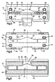
- Figure 1 is a perspective view of a vacuum cleaner nozzle having a cleaning pad installed in accordance with the claimed invention.
- Figure 2 is an exploded view of parts shown in Fig. 1.
- Figure 3 is a bottom view taken on line 3-3 of Fig. 2.
- Figure 4 is a top view taken on line 4-4 of Fig. 2.
- Figure 5 is a bottom view taken on line 5-5 of Fig. 2.
- Figure 6 is a top view taken on line 6-6 of Fig. 2.
- Figure 7 is a bottom view taken on line 7-7 of Fig. 2.
- Figure 8 is a perspective view of parts shown in Fig. 1.
- Figure 9 is a bottom view of parts shown in Fig. 1.
- The structures shown in the drawings have parts that are examples of the elements recited in the claims. The illustrated structures thus include examples of how a person of ordinary skill in the art can make and use the claimed invention. They are described here to meet the requirements of enablement and best mode without imposing limitations that are not recited in the claims.
- The
apparatus 10 shown in Fig. 1 includes avacuum cleaner nozzle 12 with a generallyrectangular body 14 and acylindrical neck 16. Atube 18 extends from theneck 16 to a source of suction for drawing a flow of working air through an intake opening at the bottom of thenozzle body 14. As further shown in Fig. 1, aframe 20 supports acleaning pad 22 on the bottom of thenozzle body 14. In addition to vacuuming, theapparatus 10 is thus equipped to perform other cleaning functions such as wet or dry mopping, scrubbing, dusting, etc., by contact of thepad 22 with the surface to be cleaned. - As viewed from the side in Fig. 2, the
nozzle body 14 has aperipheral flange 30 that turns upward at the front and rear. As viewed from beneath in Fig. 3, thenozzle body 14 has a planarlower side surface 32. Thelower side surface 32 is defined by abase plate 34 that is fitted into the space within the surroundingflange 30. Thebase plate 34 defines theintake opening 35 which, in the illustrated example, has threedistinct sections base plate 34. - A
brush bar 40 is supported within thenozzle body 14. Thebrush bar 40 supportsbristles 42 that project a short distance outward through the intake opening 35. Also shown in Fig. 3 arerollers 46 which, like thebristles 42, project a short distance downward beneath thelower side surface 32 of thebase plate 34. When theframe 20 and thecleaning pad 22 are not installed on thenozzle 12, therollers 46 can support thenozzle 12 for movement on a hard floor surface. The surface can then be cleaned by the brushing action of thebristles 42 and the stream of working air that is drawn inward through the combined flow area of the threesections - Referring again to the side view of Fig. 2, the
frame 20 has mountingflanges flange 30 on thenozzle 12. As viewed from above in Fig. 4, theframe 20 has a generally rectangular configuration closely matching the combined configuration of thebase plate 34 and theflange 30 at the bottom of thenozzle 12. Themounting flange 60 at the front of theframe 20 extends fully along its length, and has a pair oflocking tabs 64 configured to snap into releasably interlocked engagement with theflange 30 at the front of thenozzle 12. Themounting flange 62 at the rear of theframe 20 has two sections corresponding to two sections of theflange 30 at the rear of thenozzle 12, and has twolocking tabs 66 configured to snap into interlocked engagement with theflange 30 at those locations. - A planar
upper side surface 70 of theframe 20 corresponds to the planarlower side surface 32 of the base plate 34 (Fig. 3), and anintake opening 75 in theframe 20 corresponds with theintake opening 35 in thebase plate 34.Apertures 76 near the four corners of theupper side surface 70 correspond with the rectangular array ofrollers 46 at thebase plate 34. An indicator arrow 78 on theupper side surface 70 points toward the front of theframe 20. - A sponge 80 (Fig. 5) is mounted on a planar
lower side surface 82 of theframe 20. Thesponge 80 has an elongated configuration extending about the periphery of the intake opening 75. Agap 85 extends between theopposite ends sponge 80 to define a channel for a stream of debris-laden working air to reach the intake opening 75 by flowing under theframe 20 in a direction extending rearwardly across and beneath thelower side surface 82. - The
cleaning pad 22 has a structure that permits the flow of working air to pass through thepad 22. Such permeability can be accomplished by forming thepad 22 of air-permeable material and/or by perforating a pad formed of material that is not air-permeable. In the illustrated example, thecleaning pad 22 is formed of air-permeable material, and also is perforated for additional permeability as well as for the passage of debris. - More specifically, the illustrated example of a
cleaning pad 22 is a single, one-layer sheet of soft fabric with front andrear edges right edges lower side surfaces slot 112 extending through thepad 22 is large enough for the passage of relatively large debris. Theslot 112 is centered on thetransverse centerline 115 of thepad 22 and is closer to theforward edge 100 than to therear edge 102. A plurality ofslits 116 also extend through thepad 22. Theslits 116 are arranged lengthwise of thepad 22 in an array that is evenly distributed throughout the length and width of thepad 22. Theslits 116 permit the passage of working air through thepad 22, and also permit the passage of debris that is relatively small, yet larger than that which is passable by the air-permeable material of which thepad 22 is formed. - As further shown in Figs. 6 and 7, the
upper side surface 108 of thepad 22 bears installation indicia, but is otherwise the same as thelower side surface 110. The installation indicia includesarrows 120, aprimary boundary line 122, and twosecondary boundary lines 124. Thearrows 120 point toward thefront edge 100. Theprimary boundary line 122 encloses aplacement zone 126 with a size and shape closely matching that of the frame 20 (Fig. 4). Thesecondary boundary lines 124 enclosesmaller placement zones 128 on opposite sides of theslot 112. Each of thoseplacement zones 128 has a size and shape corresponding to a respective end portion of the intake opening 75 in the frame 20 (Fig. 3).Additional indicator lines 130 provide shading for greater visual contrast between theplacement zones front edge portion 132 of thepad 22 is located forward of theprimary placement zone 126. Arear edge portion 134 is located rearward of thesecondary placement zones 128. - The
cleaning pad 22 is installed on thenozzle 12 by first placing thepad 22 on a hard floor surface in the flat condition shown in Fig. 6. Theframe 20 is placed downward upon theupper side surface 108 of thepad 22, with theindicator arrow 78 pointing toward thefront edge 100 of thepad 22, and with theframe 20 arranged in overlying alignment with theplacement zones pad 22. Next, thefront edge portion 132 of thepad 22 is folded upward and backward over the mountingflange 60 at the front of theframe 20, and is placed downward in a folded position overlying theupper side surface 70 of theframe 20 at a location forward of theintake opening 75. In a similar manner, therear edge portion 132 of thepad 22 is folded upward and forward over the mountingflange 62 at the rear of theframe 20, and is placed downward onto theupper side surface 70 behind theintake opening 75. Having wrapped thepad 22 around theframe 20 as shown in Fig. 8, the user can place thenozzle 12 forcefully downward upon those parts to snap theflange 30 on thenozzle body 14 into engagement with the lockingtabs frame 20. Theedge portions pad 22 are then clamped between theflange 30 and the lockingtabs pad 22 extends across the flow area defined by the alignedintake openings nozzle 12 and theframe 20, with theslot 112 in thepad 22 projecting forward in alignment with thechannel 85 between the opposite ends of thesponge 80 on theframe 20, as shown in the bottom view of Fig. 9. - This written description sets forth the best mode of carrying out the invention, and describes the invention so as to enable a person skilled in the art to make and use the invention, by presenting examples of the elements recited in the claims. The patentable scope of the invention is defined by the claims, and may include other examples that occur to those skilled in the art. Such other examples, which may be available either before or after the application filing date, are intended to be within the scope of the claims if they have elements that do not differ from the literal language of the claims, or if they have insubstantial differences from the literal language of the claims.
Claims (16)
- An apparatus comprising:a vacuum cleaner nozzle having an intake opening with a flow area that receives a flow of working air; anda cleaning pad having a structure that permits the working air to pass through the pad, and configured to be installed over the intake opening in a position extending across the flow area.
- An apparatus for use with a vacuum cleaner nozzle having an intake opening with a flow area that receives a flow of working air, the apparatus comprising:a cleaning pad having a structure that permits the working air to pass through the pad, and configured to be installed over the intake opening in a position extending across the flow area.
- An apparatus as defined in claim 1 or 2 wherein the cleaning pad is perforated to allow passage of the flow of the working air.
- An apparatus as defined in claim 1 or 2 wherein the cleaning pad is formed of air-permeable material.
- An apparatus as defined in claim 4 wherein the cleaning pad has an aperture configured for the passage of debris larger than that which is passable by the air-permeable material.
- An apparatus as defined in claim 5 wherein the aperture is one of a plurality of debris passage apertures in the cleaning pad.
- An apparatus as defined in claim 6 wherein the cleaning pad has a relatively large debris passage aperture and a plurality of smaller debris passage apertures.
- An apparatus as defined in claim 7 wherein the relatively large debris passage aperture is a slot and the smaller debris passage apertures are slits.
- An apparatus as defined in one of the claims 1 to 8 further comprising a support structure configured to support the cleaning pad in the installed position.
- An apparatus as defined in claim 9 wherein the support structure includes a sponge.
- An apparatus as defined in claim 10 wherein the sponge is configured to define an air flow channel leading to the intake opening.
- An apparatus as defined in one of the claims 9 to 11 wherein the support structure includes a frame.
- An apparatus as defined in claim 12 wherein the frame is configured to snap into installed engagement with the nozzle and to clamp peripheral portions of the cleaning pad between the nozzle and the frame.
- An apparatus as defined in one of the previous claims wherein the cleaning pad is a sheet.
- An apparatus as defined in claim 14 wherein the cleaning pad is defined by a single layer of sheet material.
- An apparatus as defined in one of the previous claims wherein the cleaning pad has a lower side surface for contacting a surface to be cleaned, and has an upper side surface with installation indicia.
Applications Claiming Priority (1)
| Application Number | Priority Date | Filing Date | Title |
|---|---|---|---|
| US11/200,436 US7409745B2 (en) | 2005-08-09 | 2005-08-09 | Cleaning pad for vacuum cleaner |
Publications (2)
| Publication Number | Publication Date |
|---|---|
| EP1752079A2 true EP1752079A2 (en) | 2007-02-14 |
| EP1752079A3 EP1752079A3 (en) | 2008-09-17 |
Family
ID=36947575
Family Applications (1)
| Application Number | Title | Priority Date | Filing Date |
|---|---|---|---|
| EP06016364A Withdrawn EP1752079A3 (en) | 2005-08-09 | 2006-08-04 | Cleaning pad for vacuum cleaner |
Country Status (6)
| Country | Link |
|---|---|
| US (1) | US7409745B2 (en) |
| EP (1) | EP1752079A3 (en) |
| AU (1) | AU2006203368B2 (en) |
| CA (1) | CA2552501C (en) |
| NZ (1) | NZ548611A (en) |
| RU (1) | RU2327411C2 (en) |
Cited By (2)
| Publication number | Priority date | Publication date | Assignee | Title |
|---|---|---|---|---|
| EP2052658A3 (en) * | 2007-10-23 | 2009-07-15 | The Scott Fetzer Company | Vacuum cleaner nozzle with disposable cover sheet |
| EP3298943A1 (en) * | 2016-09-23 | 2018-03-28 | Wessel-Werk GmbH | Suction cleaning arrangement |
Families Citing this family (38)
| Publication number | Priority date | Publication date | Assignee | Title |
|---|---|---|---|---|
| KR100746080B1 (en) * | 2005-12-06 | 2007-08-06 | 엘지전자 주식회사 | Cleaner and Method for using the same |
| US20140130670A1 (en) | 2012-11-14 | 2014-05-15 | Peter Eisenberger | System and method for removing carbon dioxide from an atmosphere and global thermostat using the same |
| US20080289495A1 (en) * | 2007-05-21 | 2008-11-27 | Peter Eisenberger | System and Method for Removing Carbon Dioxide From an Atmosphere and Global Thermostat Using the Same |
| US8163066B2 (en) | 2007-05-21 | 2012-04-24 | Peter Eisenberger | Carbon dioxide capture/regeneration structures and techniques |
| US8500857B2 (en) | 2007-05-21 | 2013-08-06 | Peter Eisenberger | Carbon dioxide capture/regeneration method using gas mixture |
| KR20090017870A (en) * | 2007-08-16 | 2009-02-19 | 삼성광주전자 주식회사 | Suction brush for vacuum cleaner having hair removal unit |
| US20100024157A1 (en) * | 2008-07-31 | 2010-02-04 | Paul John Edward Vernon | Head for a cleaning implement |
| EP2563495B1 (en) | 2010-04-30 | 2019-09-25 | Peter Eisenberger | Method for carbon dioxide capture |
| US9028592B2 (en) | 2010-04-30 | 2015-05-12 | Peter Eisenberger | System and method for carbon dioxide capture and sequestration from relatively high concentration CO2 mixtures |
| AU2011253852B2 (en) | 2010-12-15 | 2014-06-05 | Bissell Inc. | Suction nozzle with shuttling plate and converging debris paths |
| US8438696B2 (en) | 2011-02-16 | 2013-05-14 | Techtronic Floor Care Technology Limited | Surface cleaner including a cleaning pad |
| US20130095999A1 (en) | 2011-10-13 | 2013-04-18 | Georgia Tech Research Corporation | Methods of making the supported polyamines and structures including supported polyamines |
| GB2504678B (en) * | 2012-08-03 | 2014-11-26 | Dyson Technology Ltd | A floor tool for a vacuum cleaning appliance |
| GB2504674B (en) * | 2012-08-03 | 2014-11-26 | Dyson Technology Ltd | A floor tool for a vacuum cleaning appliance |
| US11059024B2 (en) | 2012-10-25 | 2021-07-13 | Georgia Tech Research Corporation | Supported poly(allyl)amine and derivatives for CO2 capture from flue gas or ultra-dilute gas streams such as ambient air or admixtures thereof |
| EA201691356A1 (en) | 2013-12-31 | 2016-11-30 | Питер Айзенбергер | ROTATING SYSTEM FOR LAYER MOVEMENT WITH A MULTIPLE OF MONOLITHIC LAYERS TO REMOVE COAT OF THE ATMOSPHERE |
| US11518594B1 (en) | 2017-08-01 | 2022-12-06 | Garrett Dillon Smith | Vacuum wrap barrier |
| JP2020533028A (en) * | 2017-09-11 | 2020-11-19 | シャークニンジャ オペレーティング エルエルシー | Cleaning device |
| US11426038B2 (en) * | 2017-09-11 | 2022-08-30 | Sharkninja Operating Llc | Cleaning device |
| EP3873314B1 (en) | 2018-11-01 | 2023-08-30 | SharkNinja Operating LLC | Cleaning device |
| CN212853334U (en) | 2018-12-18 | 2021-04-02 | 尚科宁家运营有限公司 | Cleaning head and cleaning equipment |
| US11426044B1 (en) | 2018-12-18 | 2022-08-30 | Sharkninja Operating Llc | Cleaning device |
| CN214231225U (en) * | 2019-06-05 | 2021-09-21 | 尚科宁家运营有限公司 | Robot cleaner and cleaning pad for robot cleaner |
| JP2021016688A (en) * | 2019-07-23 | 2021-02-15 | ツインバード工業株式会社 | Nozzle device for cleaner |
| US11452414B2 (en) | 2019-10-31 | 2022-09-27 | Sharkninja Operating Llc | Replacement head for a vacuum |
| US11266283B2 (en) * | 2019-10-31 | 2022-03-08 | Sharkninja Operating Llc | Replacement head for a vacuum |
| US10959584B1 (en) | 2019-10-31 | 2021-03-30 | Sharkninja Operating Llc | Replacement head for a vacuum |
| US11219345B2 (en) | 2019-10-31 | 2022-01-11 | Sharkninja Operating Llc | Replacement head for a vacuum |
| USD946843S1 (en) | 2020-02-14 | 2022-03-22 | Sharkninja Operating Llc | Cleaning device |
| USD946223S1 (en) | 2020-02-14 | 2022-03-15 | Sharkninja Operating Llc | Cleaning device |
| US11471019B2 (en) | 2020-02-14 | 2022-10-18 | Sharkninja Operating Llc | Cleaning device with lights |
| USD946842S1 (en) | 2020-02-14 | 2022-03-22 | Sharkninja Operating Llc | Cleaning device |
| USD946226S1 (en) | 2020-02-14 | 2022-03-15 | Sharkninja Operating Llc | Cleaning device |
| US11179014B2 (en) | 2020-02-19 | 2021-11-23 | Sharkninja Operating Llc | Cleaning device system and method for use |
| US10952580B1 (en) | 2020-02-19 | 2021-03-23 | Sharkninja Operating Llc | Cleaning device with rotatable head |
| DE102021122305A1 (en) | 2021-08-27 | 2023-03-02 | Leifheit Aktiengesellschaft | Additional component for a floor cleaning device and floor cleaning device |
| EP4274461A1 (en) | 2022-01-11 | 2023-11-15 | Philips Domestic Appliances Holding B.V. | Cleaner head and wet cleaning apparatus comprising the same |
| EP4209158A1 (en) * | 2022-01-11 | 2023-07-12 | Versuni Holding B.V. | Cleaning element, cleaner head and wet cleaning apparatus |
Citations (3)
| Publication number | Priority date | Publication date | Assignee | Title |
|---|---|---|---|---|
| US4833752A (en) * | 1988-08-08 | 1989-05-30 | Merrick John T | Vacuum mop head |
| US5557823A (en) * | 1995-05-26 | 1996-09-24 | Jma & Associates | Vacuum cleaner attachment |
| US20040020007A1 (en) * | 2002-07-30 | 2004-02-05 | John Lausevic | Vacuum cleaner attachment for fungi removal and method of use thereof |
Family Cites Families (16)
| Publication number | Priority date | Publication date | Assignee | Title |
|---|---|---|---|---|
| US2873465A (en) * | 1955-03-25 | 1959-02-17 | George J Miller | Floor polishing attachment for vacuum cleaners |
| DE2024616B2 (en) * | 1970-05-20 | 1971-08-05 | Schwab geb Gitschel, Hilde, Zem bold, Heinz, 4000 Dusseldorf | DEVICE FOR CLEANING TEXTILES |
| GB1340466A (en) * | 1971-05-12 | 1973-12-12 | Allstar Verbrauchsgueter Gmbh | Nozzle for vacuum cleaner |
| US3820189A (en) * | 1972-12-11 | 1974-06-28 | E Roth | Brush adaptor for vacuuming |
| US4319379A (en) * | 1980-04-29 | 1982-03-16 | Carrigan William J | Pickup |
| EP0600225A1 (en) | 1991-07-22 | 1994-06-08 | VORWERK & CO. INTERHOLDING GmbH | Hand-held vacuum cleaner |
| US5399381A (en) * | 1994-02-07 | 1995-03-21 | Randall; Debbie | Protective floor cover for electric brooms |
| US5537711A (en) * | 1995-05-05 | 1996-07-23 | Tseng; Yu-Che | Electric board cleaner |
| US5655258A (en) * | 1996-03-12 | 1997-08-12 | Heintz; J. Aaron | Device for aspirating fluids from hospital operating room floor |
| US5909755A (en) * | 1997-09-29 | 1999-06-08 | Leal; Margo Gene | Vacuum dust mop |
| US6260232B1 (en) * | 1998-09-22 | 2001-07-17 | Marc O. Nelson | Surface cleaning apparatus |
| DE19933449C1 (en) | 1999-07-16 | 2000-11-16 | Wessel Werk Gmbh | Electric vacuum cleaner suction tool for hard floors has polishing elements for cleaned floor surface positioned behind and to either side of suction opening in base plate of suction tool |
| US7013528B2 (en) * | 2002-01-28 | 2006-03-21 | Bissell Homecare, Inc. | Floor cleaner with dusting |
| US6966098B2 (en) * | 2003-02-27 | 2005-11-22 | Matsushita Electric Industrial Co., Ltd. | Cleaner |
| DE10324260B4 (en) | 2003-05-28 | 2008-01-03 | Wessel-Werk Gmbh | Vacuum cleaner nozzle for smooth floors |
| JP3882191B2 (en) * | 2003-06-13 | 2007-02-14 | ツインバード工業株式会社 | Electric vacuum cleaner |
-
2005
- 2005-08-09 US US11/200,436 patent/US7409745B2/en not_active Expired - Fee Related
-
2006
- 2006-07-19 CA CA002552501A patent/CA2552501C/en not_active Expired - Fee Related
- 2006-07-19 NZ NZ548611A patent/NZ548611A/en not_active IP Right Cessation
- 2006-08-04 EP EP06016364A patent/EP1752079A3/en not_active Withdrawn
- 2006-08-08 AU AU2006203368A patent/AU2006203368B2/en not_active Ceased
- 2006-08-08 RU RU2006128828/12A patent/RU2327411C2/en not_active IP Right Cessation
Patent Citations (3)
| Publication number | Priority date | Publication date | Assignee | Title |
|---|---|---|---|---|
| US4833752A (en) * | 1988-08-08 | 1989-05-30 | Merrick John T | Vacuum mop head |
| US5557823A (en) * | 1995-05-26 | 1996-09-24 | Jma & Associates | Vacuum cleaner attachment |
| US20040020007A1 (en) * | 2002-07-30 | 2004-02-05 | John Lausevic | Vacuum cleaner attachment for fungi removal and method of use thereof |
Cited By (3)
| Publication number | Priority date | Publication date | Assignee | Title |
|---|---|---|---|---|
| EP2052658A3 (en) * | 2007-10-23 | 2009-07-15 | The Scott Fetzer Company | Vacuum cleaner nozzle with disposable cover sheet |
| AU2008207571B2 (en) * | 2007-10-23 | 2010-03-04 | The Scott Fetzer Company | Vacuum cleaner nozzle with disposable cover sheet |
| EP3298943A1 (en) * | 2016-09-23 | 2018-03-28 | Wessel-Werk GmbH | Suction cleaning arrangement |
Also Published As
| Publication number | Publication date |
|---|---|
| US20070033767A1 (en) | 2007-02-15 |
| RU2006128828A (en) | 2008-02-27 |
| EP1752079A3 (en) | 2008-09-17 |
| CA2552501A1 (en) | 2007-02-09 |
| CA2552501C (en) | 2008-09-30 |
| NZ548611A (en) | 2007-10-26 |
| US7409745B2 (en) | 2008-08-12 |
| AU2006203368A1 (en) | 2007-03-01 |
| AU2006203368B2 (en) | 2008-12-04 |
| RU2327411C2 (en) | 2008-06-27 |
Similar Documents
| Publication | Publication Date | Title |
|---|---|---|
| US7409745B2 (en) | Cleaning pad for vacuum cleaner | |
| RU2399363C2 (en) | Vacuum cleaner nozzle with disposable pad | |
| DE60318747T2 (en) | VACUUM CLEANER WITH CLEANING CLOTH | |
| US6119298A (en) | Disposable wiping sheet | |
| US8567009B2 (en) | Suction nozzle with shuttling plate and converging debris paths | |
| US20040148732A1 (en) | Endpiece for a vacuum cleaner | |
| JP5913226B2 (en) | Vacuum cleaner floor tools | |
| JP2013141610A (en) | Floor tool for vacuum cleaning appliance | |
| JPH1014839A (en) | Sheet of cleaning material | |
| KR101356530B1 (en) | Suction nozzle for vacuum cleaner | |
| US8220103B1 (en) | Mop/pad system | |
| US5850669A (en) | Vacuum cleaner head | |
| DE60201331T2 (en) | CLEANING HEAD FOR A VACUUM CLEANER | |
| JPH0928638A (en) | Nozzle with mop for vacuum cleaner | |
| JP3127062U (en) | Suction nozzle for vacuum cleaner | |
| CN203591222U (en) | Accessory tool capable of being connected onto vacuum cleaner | |
| KR20030047607A (en) | Device for assembling subsidary tools to main body for vacuum cleaner | |
| GB2374523A (en) | Vacuum cleaner suction head | |
| JPH08140913A (en) | Cleaning brush | |
| KR20050088903A (en) | Nozzle for a vacuum cleaner | |
| JPH11253369A (en) | Suction tool for vacuum cleaner and dust attaching member used therefor | |
| JP3691337B2 (en) | Suction vacuum cleaner nozzle | |
| JPS6217020Y2 (en) | ||
| CN212015453U (en) | Cleaning device | |
| JPS61240929A (en) | Floor nozzle for electric cleaner |
Legal Events
| Date | Code | Title | Description |
|---|---|---|---|
| PUAI | Public reference made under article 153(3) epc to a published international application that has entered the european phase |
Free format text: ORIGINAL CODE: 0009012 |
|
| AK | Designated contracting states |
Kind code of ref document: A2 Designated state(s): AT BE BG CH CY CZ DE DK EE ES FI FR GB GR HU IE IS IT LI LT LU LV MC NL PL PT RO SE SI SK TR |
|
| AX | Request for extension of the european patent |
Extension state: AL BA HR MK YU |
|
| PUAL | Search report despatched |
Free format text: ORIGINAL CODE: 0009013 |
|
| AK | Designated contracting states |
Kind code of ref document: A3 Designated state(s): AT BE BG CH CY CZ DE DK EE ES FI FR GB GR HU IE IS IT LI LT LU LV MC NL PL PT RO SE SI SK TR |
|
| AX | Request for extension of the european patent |
Extension state: AL BA HR MK RS |
|
| 17P | Request for examination filed |
Effective date: 20081030 |
|
| AKX | Designation fees paid |
Designated state(s): AT BE BG CH CY CZ DE DK EE ES FI FR GB GR HU IE IS IT LI LT LU LV MC NL PL PT RO SE SI SK TR |
|
| GRAP | Despatch of communication of intention to grant a patent |
Free format text: ORIGINAL CODE: EPIDOSNIGR1 |
|
| GRAC | Information related to communication of intention to grant a patent modified |
Free format text: ORIGINAL CODE: EPIDOSCIGR1 |
|
| STAA | Information on the status of an ep patent application or granted ep patent |
Free format text: STATUS: THE APPLICATION IS DEEMED TO BE WITHDRAWN |
|
| 18D | Application deemed to be withdrawn |
Effective date: 20120301 |