EP3873314B1 - Cleaning device - Google Patents
Cleaning device Download PDFInfo
- Publication number
- EP3873314B1 EP3873314B1 EP19880507.9A EP19880507A EP3873314B1 EP 3873314 B1 EP3873314 B1 EP 3873314B1 EP 19880507 A EP19880507 A EP 19880507A EP 3873314 B1 EP3873314 B1 EP 3873314B1
- Authority
- EP
- European Patent Office
- Prior art keywords
- collection chamber
- air filter
- inlet opening
- debris
- chamber
- Prior art date
- Legal status (The legal status is an assumption and is not a legal conclusion. Google has not performed a legal analysis and makes no representation as to the accuracy of the status listed.)
- Active
Links
- 238000004140 cleaning Methods 0.000 title claims description 70
- 239000000463 material Substances 0.000 claims description 42
- 230000002401 inhibitory effect Effects 0.000 claims description 3
- 239000013013 elastic material Substances 0.000 claims description 2
- 239000003381 stabilizer Substances 0.000 description 10
- 239000010410 layer Substances 0.000 description 9
- 238000000034 method Methods 0.000 description 6
- 239000007788 liquid Substances 0.000 description 5
- 230000002745 absorbent Effects 0.000 description 3
- 239000002250 absorbent Substances 0.000 description 3
- 230000004044 response Effects 0.000 description 3
- 239000000428 dust Substances 0.000 description 2
- 239000004033 plastic Substances 0.000 description 2
- 229920003023 plastic Polymers 0.000 description 2
- 238000003856 thermoforming Methods 0.000 description 2
- 230000032258 transport Effects 0.000 description 2
- 238000010521 absorption reaction Methods 0.000 description 1
- 230000003213 activating effect Effects 0.000 description 1
- 239000000853 adhesive Substances 0.000 description 1
- 230000001070 adhesive effect Effects 0.000 description 1
- 239000012530 fluid Substances 0.000 description 1
- 238000002347 injection Methods 0.000 description 1
- 239000007924 injection Substances 0.000 description 1
- 238000012986 modification Methods 0.000 description 1
- 230000004048 modification Effects 0.000 description 1
- 239000010813 municipal solid waste Substances 0.000 description 1
- 238000012856 packing Methods 0.000 description 1
- 230000008569 process Effects 0.000 description 1
- 238000005201 scrubbing Methods 0.000 description 1
- 239000002356 single layer Substances 0.000 description 1
- 230000002123 temporal effect Effects 0.000 description 1
Images


Classifications
-
- A—HUMAN NECESSITIES
- A47—FURNITURE; DOMESTIC ARTICLES OR APPLIANCES; COFFEE MILLS; SPICE MILLS; SUCTION CLEANERS IN GENERAL
- A47L—DOMESTIC WASHING OR CLEANING; SUCTION CLEANERS IN GENERAL
- A47L9/00—Details or accessories of suction cleaners, e.g. mechanical means for controlling the suction or for effecting pulsating action; Storing devices specially adapted to suction cleaners or parts thereof; Carrying-vehicles specially adapted for suction cleaners
- A47L9/10—Filters; Dust separators; Dust removal; Automatic exchange of filters
- A47L9/14—Bags or the like; Rigid filtering receptacles; Attachment of, or closures for, bags or receptacles
- A47L9/1409—Rigid filtering receptacles
-
- A—HUMAN NECESSITIES
- A47—FURNITURE; DOMESTIC ARTICLES OR APPLIANCES; COFFEE MILLS; SPICE MILLS; SUCTION CLEANERS IN GENERAL
- A47L—DOMESTIC WASHING OR CLEANING; SUCTION CLEANERS IN GENERAL
- A47L5/00—Structural features of suction cleaners
- A47L5/12—Structural features of suction cleaners with power-driven air-pumps or air-compressors, e.g. driven by motor vehicle engine vacuum
- A47L5/22—Structural features of suction cleaners with power-driven air-pumps or air-compressors, e.g. driven by motor vehicle engine vacuum with rotary fans
- A47L5/28—Suction cleaners with handles and nozzles fixed on the casings, e.g. wheeled suction cleaners with steering handle
-
- A—HUMAN NECESSITIES
- A47—FURNITURE; DOMESTIC ARTICLES OR APPLIANCES; COFFEE MILLS; SPICE MILLS; SUCTION CLEANERS IN GENERAL
- A47L—DOMESTIC WASHING OR CLEANING; SUCTION CLEANERS IN GENERAL
- A47L9/00—Details or accessories of suction cleaners, e.g. mechanical means for controlling the suction or for effecting pulsating action; Storing devices specially adapted to suction cleaners or parts thereof; Carrying-vehicles specially adapted for suction cleaners
- A47L9/02—Nozzles
- A47L9/06—Nozzles with fixed, e.g. adjustably fixed brushes or the like
- A47L9/066—Nozzles with fixed, e.g. adjustably fixed brushes or the like with adjustably mounted brushes, combs, lips or pads; Height adjustment of nozzle or dust loosening tools
-
- A—HUMAN NECESSITIES
- A47—FURNITURE; DOMESTIC ARTICLES OR APPLIANCES; COFFEE MILLS; SPICE MILLS; SUCTION CLEANERS IN GENERAL
- A47L—DOMESTIC WASHING OR CLEANING; SUCTION CLEANERS IN GENERAL
- A47L9/00—Details or accessories of suction cleaners, e.g. mechanical means for controlling the suction or for effecting pulsating action; Storing devices specially adapted to suction cleaners or parts thereof; Carrying-vehicles specially adapted for suction cleaners
- A47L9/10—Filters; Dust separators; Dust removal; Automatic exchange of filters
- A47L9/12—Dry filters
- A47L9/122—Dry filters flat
Definitions
- Embodiments disclosed herein related generally to cleaning devices, and more specifically to vacuums and cleaning heads for vacuums.
- Cleaning devices are used in the home and office to clean floors and other surfaces.
- Various types of cleaning devices are known, such as vacuums with disposable bags, and vacuums with dirt bins that can be emptied and re-used.
- An apparatus according to the preamble of claim 1 is already known e.g. from EP-A-1980188 .
- an apparatus includes a debris collection chamber, an air filter configured to allow air to pass through the air filter while inhibiting debris from passing through the air filter, and a collection chamber inlet opening configured to allow debris-entrained air to flow into the collection chamber.
- the air filter is movable from a first position, in which the air filter covers the chamber inlet opening, to a second position in which the air filter does not cover the chamber inlet opening.
- an apparatus adapted to be attached to a vacuum cleaner includes a debris collection chamber and a collection chamber inlet opening configured to allow debris-entrained air to flow into the debris collection chamber.
- the apparatus also includes an air filter configured to allow air to pass through the air filter while inhibiting debris from passing through the air filter.
- a cover is provided which is movable from a first position in which the cover covers the chamber inlet opening, to a second position in which the cover does not cover the chamber inlet opening.
- the cover is attached to the air filter, and the air filter is arranged such that when the air filter is under no negative pressure, the cover is in the first position.
- the air filter is also arranged such that when negative pressure is applied to the air filter to draw air through the chamber inlet opening, the air filter moves the cover to the second position.
- an apparatus adapted to be attached to a cleaning device having a suction source.
- the apparatus includes a debris collection chamber having a chamber wall that moves when negative pressure is applied to the collection chamber, and a collection chamber inlet opening configured to allow air to flow into the debris collection chamber when negative pressure is applied to the debris collection chamber.
- the apparatus also includes a cover movable from a first position, in which the cover covers the chamber inlet opening, to a second position in which the cover does not cover the chamber inlet opening.
- the cover is attached to the chamber wall and arranged such that when the chamber wall moves due to the negative pressure being applied the collection chamber, the chamber wall moves the cover from the first position to the second position in which the cover does not cover the chamber inlet opening, and a flow path is opened for debris-entrained to be drawn into the collection chamber through the chamber inlet opening.
- a method includes attaching a debris collection chamber to a vacuum cleaner, the collection chamber including a movable wall, a collection chamber inlet opening, and an inlet opening cover operatively connected to the movable wall.
- the method further includes activating a suction source that applies a negative pressure to the debris collection chamber and moves the movable wall, wherein the movement of the wall in response to the application of the negative pressure moves the inlet opening cover from a first position in which the inlet opening cover covers the inlet opening, to a second position in which the inlet opening cover does not cover the inlet opening.
- acts of deactivating the suction source, and removing the debris collection chamber from the vacuum cleaner are also included.
- a debris collection container which remains closed upon removal from the vacuum can be helpful.
- Disclosed herein are debris collection chamber arrangements which allow debris-entrained air to enter a collection chamber through an inlet opening when the vacuum cleaner is turned on.
- the collection chamber arrangements cover the inlet opening when the vacuum cleaner is turned off, which limits undesirable release of debris from the collection chamber.
- the collection chamber is disposable, and in some embodiments, the collection chamber is attached to a cleaning head, and the entire cleaning head is disposable.
- a cover for the inlet opening may be arranged to move in response to the presence of negative pressure in the vacuum cleaner.
- a planar piece of filter material may cover the inlet opening when the vacuum cleaner is off.
- the filter material pulls away from the inlet opening, thereby allowing air and debris to enter the collection chamber.
- the inflow of air substantially prevents dirt from exiting the collection chamber through the inlet opening.
- the filter material returns to its position covering the inlet opening.
- the filter material is attached to the debris collection chamber with an elastic connector.
- the elastic connector allows the filter material to be pulled away from the inlet opening when the filter material is subjected to a negative pressure by a suction source.
- no elastic connection is provided, and the inherent flexibility of the filter material allows the filter material to move away from the inlet opening.
- the cover for the inlet opening is not filter material.
- a piece of filter material may form substantially the entire top wall of a collection chamber, but include an air impermeable portion which covers and uncovers the inlet opening.
- an entire top wall of the collection chamber may be formed of a flexible material other than an air filter. The top wall may move to cover and uncover the inlet opening, while a separate portion of the collection chamber has an air outlet that applies a negative pressure to the collection chamber.
- the collection chamber may be completely enclosed to limit release of debris.
- the arrangement can also be helpful to limit spillage or egress of collected debris from the collection chamber when the user removes and/or transports the collection chamber for debris disposal.
- the collection chamber may be adapted for reuse and include an aperture which is selectively openable to discard debris from the chamber.
- the collection chamber may be adapted to be disposed of once the chamber is full.
- the collection chamber may have no openings other than the inlet opening.
- the collection chamber is not openable by a user to dispose of debris from the debris collection chamber without damaging the debris collection chamber.
- the collection chamber may be permanently attached to, and form at least a portion of, a disposable cleaning head in some embodiments, such that the entire head is disposed of after use.
- debris being suctioned into the debris collection chamber may include dry and/or wet media.
- a liquid applied to the surface may be absorbed by a cleaning sheet and/or suctioned by the vacuum into the debris collection chamber.
- the wet media may be absorbed by at least a portion of the material used to form the debris collection chamber.
- the debris collection chamber may be formed of a material which allows for fluid absorption into the material but does not allow for liquid transfer through the material. In such embodiments, liquid may not travel through the debris collection chamber.
- the material used to form the debris collection chamber may be absorptive on an inner side of the debris collection chamber, but liquid impermeable.
- the cleaning device may be arranged to release the cleaning head after using the cleaning device such that the user does not have to grasp the cleaning head to discard it.
- the cleaning head With a permanently attached debris collection chamber, and a release arrangement that does not require the user to touch the cleaning head, the cleaning head can be disposed of with limited or no user contact.
- the cleaning head includes a support structure to which the debris collection chamber is attached.
- the user may simply attach the cleaning head to the cleaning device, operate the cleaning device to move dirt from the surface and into the debris collection chamber, remove the cleaning head, and dispose of the cleaning head in a trash receptacle.
- the cleaning heads are arranged for space-efficient stacking for ease of storage and transport.
- the dirt collection chambers are arranged to be collapsible.
- the dirt collection chamber may include a bag.
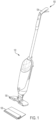
- FIG. 1 shows a cleaning device 100 according to some embodiments of the present disclosure.
- the cleaning device 100 includes a body 102 with a handle 104, a connector 106, and a cleaning head 108 which is removably attachable to the body, such as via the connector.
- the handle may have a length that is adjustable to allow a user to adjust the height of the cleaning device.
- the cleaning head 108 may include a suction nozzle 107 to remove debris from a surface, and a debris collection chamber 112 to collect the debris removed from the surface.
- the debris collection chamber may be any suitable type of container for collecting debris such as dirt, dust, food, or wet media.
- the debris collection chamber 112 may be permanently or removably attached to a cleaning sheet 114.
- the collection chamber 112 may be glued, heat sealed, or otherwise permanently affixed to cleaning sheet 114.
- an additional support structure may be provided.
- a substantially planar support frame may be provided between the collection chamber and the sheet, although the support structure may have other suitable arrangements.
- the collection chamber 112 protrudes upwardly from the cleaning sheet or support structure.
- protruding upwardly means that the collection chamber protrudes away from the support structure in a direction away from the surface being cleaned.
- the collection chamber 112 includes an inlet 115 having an inlet opening 116, which in the illustrated embodiment, is located at a top portion of the collection chamber 112.
- the inlet opening 116 is formed by a top rim 118 of an upwardly extending wall 120.
- the inlet 115 may have a ramp 122 extending from a suction inlet 124 into the collection chamber to aid in moving debris from the suction inlet into collection areas 126a, 126b of the collection chamber.
- the area below the inlet opening may have a floor that is coplanar with a bottom 127 of the collection portions of the collection chamber 112.
- An air filter 128 forms a top wall of the collection chamber in some embodiments.
- the filter material may be attached to the collection chamber such that in a first position, as shown in FIG. 2 , the air filter covers inlet opening 116. In this position, the air filter inhibits debris that has already been collected in collection areas 126a, 126b from moving over wall 120 and through the inlet opening 116.
- the air filter and the collection chamber are arranged such that the air filter is in this first position when negative pressure is not being applied to the air filter.
- the air filter may be attached to the collection chamber with an elastic connection.
- an elongated strip 136 of elastic material connects the air filter to a top portion of the collection chamber along a front wall of the collection chamber.
- a similar elongated elastic strip connects the air filter to the top portion of the collection chamber along the rear wall of the collection chamber. The stretchability of the elongated strips allows the air filter to move away from the inlet opening.
- elastic connectors may be used on one or both of the walls at the lateral sides of the collection chamber.
- only a portion of the air filter 128 may rise from the collection chamber when negative pressure is applied to the cleaning head.
- elastic connectors may be provided along only certain portions of the air filter. The elastic portions may be provided in an area of the air inlet opening such that the air filter lifts only in the area at or near the air inlet opening, while the remaining areas of the air filter are not substantially lifted.
- the air filter may be connected to the collection chamber without any elastic connectors such that the air filter does not move at the connection points.
- the air filter may have a size and shape which allows the air filter to sufficiently lift away from the air inlet opening when under negative pressure such that the cover lifts away from the air inlet opening.
- adhesive strips 123 may be provided on the filter material 128, to secure the filter material to the collection chamber, as shown by way of example in FIG. 3 .
- a section of air impermeable material may be used in the area of the top wall of the collection chamber as a cover 134 for the inlet opening.
- Cover 134 may have the same shape as a perimeter of the chamber inlet opening, or it may have a different shape.
- an underside of cover 134 may be provided with an additional material layer.
- a layer of material which conforms easily to rim 118 may be adhered to an underside of the air filter. Such a layer may act to seal the inlet opening against passage of debris.
- top wall outside of the cover 134 are shown as air filter 128 in the embodiment of FIG. 7 , but other materials may be used to form the top wall of the collection chamber.
- the entire top wall may be air impermeable, and one or more air filters may be provided elsewhere in the arrangement, as discuss below with reference to FIG. 11 .
- the collection chamber may include stiffening ridges 137 along a bottom of the collection chamber.
- the stiffening ridges may allow for less material to be used in forming the collection chamber.
- the stiffening ridges are shown traveling from front to back in the collection chamber, however, stiffening ridges may be positioned and sized in any suitable manner. Stiffening grooves may be used instead of, or in addition to, stiffening ridges.
- the collection chamber is formed with a plastic thermoforming process.
- the collection chamber may be manufactured using any suitable process.
- the collection chamber may be injection molded.
- the collection chamber, the suction nozzle, and the suction inlet may be a unitary piece.
- the collection chamber, the suction nozzle, and the inlet may be integrally formed, such as by thermoforming.
- one more of the collection chamber, the suction nozzle, and the suction inlet may be separately formed and attached.
- a cleaning sheet may be attached to the collection chamber.
- the cleaning sheet may be formed of any suitable material, and may be made of a single layer or multiple layers.
- the cleaning sheet includes multiple layers including a multifunctional strip 138, a face layer 139, and first and second absorbent layers 140 and 141.
- the face layer and absorbent layers may be made from various non-woven materials, woven materials, and/or plastics, or any other suitable materials.
- the absorbent layers may be configured to wick moisture away from the face layer.
- the multifunctional strip 138 may be used for scrubbing in some embodiments. In some embodiments, the multifunctional strip may provide friction to help prevent the cleaning device from slipping when propped against a wall.
- the air filter material may be limited to specific sections of the collection chamber.
- a top chamber wall similarly arranged to the air filter 128 shown in FIG. 7 may have air permeable sections only at or near lateral ends of the top chamber wall, and have air impermeable material in the remaining section.
- air permeable sections may be positioned close to a centered inlet opening on both sides of the inlet opening.
- a collection chamber may include more than one inlet opening and a cover for each of the openings.
- a cover may include portions which extended downwardly into the inlet opening and/or around the outside of the chamber inlet opening.
- a collar may be attached to an underside of the air filter such that when the vacuum cleaner is turned off and the air filter returns to a home position, the collar cover some or all of the perimeter of the inlet opening.
- FIG. 8 One example of such an embodiment is shown in FIG. 8 .
- a collar 142 is connected to an underside of air filter 124. When the air filter is moved to a home position, the collar is positioned next to, or in contact with, an outside of wall 120. The air filter and is shown slightly higher than the home position in FIG. 8 .
- the collar may be made of a rigid material or may be made of a flexible material.
- FIG. 9 shows an embodiment where a downwardly extending member is positioned inside the inlet opening when the air filter is in the home position.
- a collar 144 is adapted to be positioned next or in contact with an inside of wall 120.
- the collar may be made of a rigid material or a flexible material.
- the downwardly extending cover structures shown in FIGS. 8 and 9 may be used in addition to or instead of a substantially horizontal cover portion of the air filter.
- a cover stabilizer may be implemented to help maintain contact between the cover and the rim of the inlet opening.
- a cover stabilizer 150 has a similar shape to the rim of the outlet opening shown in FIGS. 3-4 .
- Stabilizer 150 is pivotally attached to the air filter at a pivot joint 152, and is biased downwardly by a torsion spring 154.
- the force applied by the stabilizer 150 may press the underside of air filter 128 in to secure contact with the rim of the air inlet opening.
- the weight of the stabilizer and the strength of the torsion spring may be configured such that when the air filter is lifted from the collection chamber, the stabilizer does not overly deforms the shape of the air filter.
- a mechanical limit to the rotation of the stabilizer may be implemented, for example at the pivot joint 152.
- a conduit end does not have to be fully exposed to be considered to be an inlet opening that is not covered by a cover.
- the air inlet opening for a debris collection chamber is formed by an upright cylindrical column with a top circular rim, and an air filter is removed from a sufficient portion of the circular rim during vacuuming to permit flow of air and debris into the collection chamber, the air inlet opening may be considered to be not covered by the air inlet opening cover.
- FIG. 11 shows one embodiment where the air filter 128 is attached to the collection chamber with a pleated material 129.
- the air filter 128 is shown slightly lifted from the collection chamber in FIG. 11 .
- a cover stabilizer such as the stabilizer shown in FIG. 10 , may be used in conjunction with a pleated arrangement or other non-elastic arrangement.
- the pleated material may be formed of an air filter material.
- the top wall may be formed with an air impermeable material, and the vacuum cleaner may be configured to encompass at least the top wall and the pleated sides. When negative pressure is applied, the top wall is lifted upwardly, exposing the air filter material of the pleated sides. Air is then withdrawn from the collection chamber via the pleated sides.
- the air filter may be positioned elsewhere on the collection chamber and still function as a removable cover for the chamber inlet opening.
- the chamber inlet opening may face rearwardly, and the air filter may be positioned at the back of the collection chamber.
- the air filter may be held against the chamber inlet opening, for example with elastic connectors, to cover the inlet opening. When negative pressure is applied, the air filter be moved away from the chamber inlet opening.
- a movable wall may be a flexible bag structure.
- a wall is not necessarily required to be planar or rigid.
- an entire debris collection chamber may be formed as a flexible bag attached to the chamber inlet opening. A portion of the bag may be positioned against the chamber inlet opening when no negative pressure is applied, and then as the bag expands from the application of negative pressure, the portion of the bag covering the chamber inlet opening moves away to allow debris-entrained air to enter the bag.
- walls may be planar and/or rigid, and collection chambers may have a combination of rigid and flexible walls.
- Applying a negative pressure to a collection chamber includes applying a negative pressure to the outside of an air permeable portion of the chamber and/or applying a negative pressure to an opening in the collection chamber.
- the cleaning head when the cleaning head is attached to the cleaning device, at least a portion of the debris collection chamber may be covered by the cleaning device.
- the debris collection chamber may be covered by the connector 106 used to connect the cleaning head to the cleaning device.
- a divider 160 may be provided to stiffen the collection chamber, though some embodiments include no such divider. Additional walls similar to divider 160 may be positioned in the collection chamber to guide air flow within the collection chamber.
- Suction nozzle 107 may extend laterally along a front portion of the cleaning head.
- the suction nozzle may have any suitable shape and size.
- the suction nozzle may extend along an entire width of the cleaning head in some embodiments.
- the suction nozzle may be formed on part of the vacuum cleaner device. In such an embodiment, once the collection chamber is attached to the vacuum cleaner, the suction nozzle forms a flow path to the collection chamber inlet opening.
- the vacuum cleaner may include one or more actuators for actuating the suction source, and one or more actuators for actuating liquid application.
- the suction source may be an electric motor in some embodiments.
- Cleaning heads described herein may be constructed and arranged to permit efficient packing in some embodiments.
- the debris collection chamber and suction nozzle may be sized and positioned on a cleaning sheet and/or support structure such that an inverted cleaning head is stackable on an upright cleaning in such a manner that the upwardly-facing surface is substantially level.
- eight cleaning heads 108 are stacked, and the cleaning heads alternate between being upright and being inverted.
- the suction nozzles 107 are sized and position to not interfere with the adjacently stacked cleaning heads.
- embodiments of the invention may be embodied as a method, of which an example has been provided.
- the acts performed as part of the method may be ordered in any suitable way. Accordingly, embodiments may be constructed in which acts are performed in an order different than illustrated, which may include performing some acts simultaneously, even though shown as sequential acts in illustrative embodiments.
Description
- Embodiments disclosed herein related generally to cleaning devices, and more specifically to vacuums and cleaning heads for vacuums.
- Cleaning devices are used in the home and office to clean floors and other surfaces. Various types of cleaning devices are known, such as vacuums with disposable bags, and vacuums with dirt bins that can be emptied and re-used. An apparatus according to the preamble of claim 1 is already known e.g. from
EP-A-1980188 . - According to one embodiment, an apparatus includes a debris collection chamber, an air filter configured to allow air to pass through the air filter while inhibiting debris from passing through the air filter, and a collection chamber inlet opening configured to allow debris-entrained air to flow into the collection chamber. The air filter is movable from a first position, in which the air filter covers the chamber inlet opening, to a second position in which the air filter does not cover the chamber inlet opening.
- According to another embodiment, an apparatus adapted to be attached to a vacuum cleaner includes a debris collection chamber and a collection chamber inlet opening configured to allow debris-entrained air to flow into the debris collection chamber. The apparatus also includes an air filter configured to allow air to pass through the air filter while inhibiting debris from passing through the air filter. A cover is provided which is movable from a first position in which the cover covers the chamber inlet opening, to a second position in which the cover does not cover the chamber inlet opening. The cover is attached to the air filter, and the air filter is arranged such that when the air filter is under no negative pressure, the cover is in the first position. The air filter is also arranged such that when negative pressure is applied to the air filter to draw air through the chamber inlet opening, the air filter moves the cover to the second position.
- According to yet another embodiment, an apparatus adapted to be attached to a cleaning device having a suction source is provided. The apparatus includes a debris collection chamber having a chamber wall that moves when negative pressure is applied to the collection chamber, and a collection chamber inlet opening configured to allow air to flow into the debris collection chamber when negative pressure is applied to the debris collection chamber. The apparatus also includes a cover movable from a first position, in which the cover covers the chamber inlet opening, to a second position in which the cover does not cover the chamber inlet opening. The cover is attached to the chamber wall and arranged such that when the chamber wall moves due to the negative pressure being applied the collection chamber, the chamber wall moves the cover from the first position to the second position in which the cover does not cover the chamber inlet opening, and a flow path is opened for debris-entrained to be drawn into the collection chamber through the chamber inlet opening.
- According to another embodiment, a method includes attaching a debris collection chamber to a vacuum cleaner, the collection chamber including a movable wall, a collection chamber inlet opening, and an inlet opening cover operatively connected to the movable wall. The method further includes activating a suction source that applies a negative pressure to the debris collection chamber and moves the movable wall, wherein the movement of the wall in response to the application of the negative pressure moves the inlet opening cover from a first position in which the inlet opening cover covers the inlet opening, to a second position in which the inlet opening cover does not cover the inlet opening. Also included are acts of deactivating the suction source, and removing the debris collection chamber from the vacuum cleaner.
- It should be appreciated that the foregoing concepts, and additional concepts discussed below, may be arranged in any suitable combination, as the present disclosure is not limited in this respect.
- The foregoing and other aspects, embodiments, and features of the present teachings can be more fully understood from the following description in conjunction with the accompanying drawings.
- The accompanying drawings are not intended to be drawn to scale. In the drawings, each identical or nearly identical component that is illustrated in various figures is represented by a like numeral. For purposes of clarity, not every component may be labeled in every drawing. In the drawings:
-
FIG. 1 is a perspective view of a cleaning device according to embodiments of the present disclosure; -
FIG. 2 is a top, front perspective view of a cleaning head according to some embodiments; -
FIG. 3 is an exploded view of the cleaning head ofFIG. 2 ; -
FIG. 4 is a top, rear perspective view of the cleaning head ofFIG. 2 with the filter removed; -
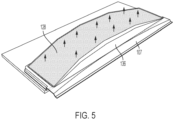
FIG. 5 shows the cleaning head ofFIG. 2 in a state where negative pressure is being applied to the collection chamber; -
FIG. 6 is a cutaway view of the cleaning head ofFIG. 2 ; -
FIG. 7 is an exploded view of the cleaning head and sheet assembly; -
FIG. 8 is a cross-sectional front view of a cleaning head and a partially lifted top chamber wall according to some embodiments; -
FIG. 9 is a cross-sectional front view of a cleaning head and a partially lifted top chamber wall according to alternative embodiments; -
FIG. 10 shows a cover stabilizer according to some embodiments; -
FIG. 11 is a cross-sectional side view of a cleaning head with a chamber inlet cover arrangement according to some embodiments; and -
FIG. 12 shows eight stacked cleaning heads according to some embodiments. - Conventional bag vacuums typically require the user to remove a bag from a housing interior, dispose of the bag, and insert a new bag. Removing the bag can put dust in the air and/or result in spilled debris. Cyclonic vacuum cleaners often have a debris collection chamber that can be removed from the body of the vacuum, emptied, and reused.
- For cleanup jobs that do not require a full size vacuum cleaner, the inventors have appreciated that a debris collection container which remains closed upon removal from the vacuum can be helpful. Disclosed herein are debris collection chamber arrangements which allow debris-entrained air to enter a collection chamber through an inlet opening when the vacuum cleaner is turned on. The collection chamber arrangements cover the inlet opening when the vacuum cleaner is turned off, which limits undesirable release of debris from the collection chamber. In some embodiments, the collection chamber is disposable, and in some embodiments, the collection chamber is attached to a cleaning head, and the entire cleaning head is disposable.
- To facilitate covering the collection chamber inlet opening, a cover for the inlet opening may be arranged to move in response to the presence of negative pressure in the vacuum cleaner. For example, a planar piece of filter material may cover the inlet opening when the vacuum cleaner is off. When the vacuum cleaner is turned on and negative pressure is applied to the filter material, the filter material pulls away from the inlet opening, thereby allowing air and debris to enter the collection chamber. The inflow of air substantially prevents dirt from exiting the collection chamber through the inlet opening. When the vacuum cleaners turned off, the filter material returns to its position covering the inlet opening. Such an arrangement provides for covering the inlet opening without user intervention.
- In some embodiments, the filter material is attached to the debris collection chamber with an elastic connector. The elastic connector allows the filter material to be pulled away from the inlet opening when the filter material is subjected to a negative pressure by a suction source. In other embodiments, no elastic connection is provided, and the inherent flexibility of the filter material allows the filter material to move away from the inlet opening.
- In some embodiments, the cover for the inlet opening is not filter material. For example, a piece of filter material may form substantially the entire top wall of a collection chamber, but include an air impermeable portion which covers and uncovers the inlet opening. In still other embodiments, an entire top wall of the collection chamber may be formed of a flexible material other than an air filter. The top wall may move to cover and uncover the inlet opening, while a separate portion of the collection chamber has an air outlet that applies a negative pressure to the collection chamber.
- By automatically closing the chamber inlet opening when the vacuum cleaner is turned off, the collection chamber may be completely enclosed to limit release of debris. The arrangement can also be helpful to limit spillage or egress of collected debris from the collection chamber when the user removes and/or transports the collection chamber for debris disposal. In some embodiments, the collection chamber may be adapted for reuse and include an aperture which is selectively openable to discard debris from the chamber. In other embodiments, the collection chamber may be adapted to be disposed of once the chamber is full. For example, in some embodiments the collection chamber may have no openings other than the inlet opening. In some embodiments, the collection chamber is not openable by a user to dispose of debris from the debris collection chamber without damaging the debris collection chamber. The collection chamber may be permanently attached to, and form at least a portion of, a disposable cleaning head in some embodiments, such that the entire head is disposed of after use.
- For purposes herein, debris being suctioned into the debris collection chamber may include dry and/or wet media. For example, in some embodiments, a liquid applied to the surface may be absorbed by a cleaning sheet and/or suctioned by the vacuum into the debris collection chamber. In some embodiments, the wet media may be absorbed by at least a portion of the material used to form the debris collection chamber. In some embodiments, the debris collection chamber may be formed of a material which allows for fluid absorption into the material but does not allow for liquid transfer through the material. In such embodiments, liquid may not travel through the debris collection chamber. For example, the material used to form the debris collection chamber may be absorptive on an inner side of the debris collection chamber, but liquid impermeable.
- Advantages also may be realized if the user does not have to handle the wet or dirty cleaning head after operation of the cleaning device. For example, the cleaning device may be arranged to release the cleaning head after using the cleaning device such that the user does not have to grasp the cleaning head to discard it. With a permanently attached debris collection chamber, and a release arrangement that does not require the user to touch the cleaning head, the cleaning head can be disposed of with limited or no user contact.
- In some embodiments, the cleaning head includes a support structure to which the debris collection chamber is attached. In such embodiments, the user may simply attach the cleaning head to the cleaning device, operate the cleaning device to move dirt from the surface and into the debris collection chamber, remove the cleaning head, and dispose of the cleaning head in a trash receptacle.
- In some embodiments, the cleaning heads are arranged for space-efficient stacking for ease of storage and transport. In some embodiments, the dirt collection chambers are arranged to be collapsible. For example, the dirt collection chamber may include a bag.
-
FIG. 1 shows acleaning device 100 according to some embodiments of the present disclosure. Thecleaning device 100 includes abody 102 with ahandle 104, a connector 106, and acleaning head 108 which is removably attachable to the body, such as via the connector. In some embodiments, the handle may have a length that is adjustable to allow a user to adjust the height of the cleaning device. - As shown in
FIGS. 2-4 , the cleaninghead 108 may include asuction nozzle 107 to remove debris from a surface, and adebris collection chamber 112 to collect the debris removed from the surface. As will be appreciated, the debris collection chamber may be any suitable type of container for collecting debris such as dirt, dust, food, or wet media. In some embodiments, thedebris collection chamber 112 may be permanently or removably attached to acleaning sheet 114. For example, thecollection chamber 112 may be glued, heat sealed, or otherwise permanently affixed to cleaningsheet 114. - In some embodiments, an additional support structure may be provided. For example, a substantially planar support frame may be provided between the collection chamber and the sheet, although the support structure may have other suitable arrangements.
- In some embodiments, the
collection chamber 112 protrudes upwardly from the cleaning sheet or support structure. For purposes herein, the term "protruding upwardly" means that the collection chamber protrudes away from the support structure in a direction away from the surface being cleaned. - The
collection chamber 112 includes aninlet 115 having aninlet opening 116, which in the illustrated embodiment, is located at a top portion of thecollection chamber 112. Theinlet opening 116 is formed by atop rim 118 of an upwardly extendingwall 120. Theinlet 115 may have aramp 122 extending from asuction inlet 124 into the collection chamber to aid in moving debris from the suction inlet intocollection areas bottom 127 of the collection portions of thecollection chamber 112. - An
air filter 128 forms a top wall of the collection chamber in some embodiments. The filter material may be attached to the collection chamber such that in a first position, as shown inFIG. 2 , the air filter coversinlet opening 116. In this position, the air filter inhibits debris that has already been collected incollection areas wall 120 and through theinlet opening 116. The air filter and the collection chamber are arranged such that the air filter is in this first position when negative pressure is not being applied to the air filter. - When negative pressure is applied to the air filter, the air filter moves upwardly (see
FIG. 5 ) and separate from the inlet opening. In this second position, debris-entrained air can flow throughsuction inlet 124, up and overwall 120, and into thedebris collection areas - As mentioned above, the air filter may be attached to the collection chamber with an elastic connection. For example, as shown in
FIG. 5 , anelongated strip 136 of elastic material connects the air filter to a top portion of the collection chamber along a front wall of the collection chamber. A similar elongated elastic strip (not visible inFIG. 5 ) connects the air filter to the top portion of the collection chamber along the rear wall of the collection chamber. The stretchability of the elongated strips allows the air filter to move away from the inlet opening. In some embodiments, elastic connectors may be used on one or both of the walls at the lateral sides of the collection chamber. - In some embodiments, only a portion of the
air filter 128 may rise from the collection chamber when negative pressure is applied to the cleaning head. For example, elastic connectors may be provided along only certain portions of the air filter. The elastic portions may be provided in an area of the air inlet opening such that the air filter lifts only in the area at or near the air inlet opening, while the remaining areas of the air filter are not substantially lifted. - In still further embodiments, the air filter may be connected to the collection chamber without any elastic connectors such that the air filter does not move at the connection points. In such an embodiment, the air filter may have a size and shape which allows the air filter to sufficiently lift away from the air inlet opening when under negative pressure such that the cover lifts away from the air inlet opening. For example,
adhesive strips 123 may be provided on thefilter material 128, to secure the filter material to the collection chamber, as shown by way of example inFIG. 3 . - Materials other than an air filter may be used to cover the inlet opening in some embodiments. For example, as shown in
FIG. 7 , a section of air impermeable material may be used in the area of the top wall of the collection chamber as acover 134 for the inlet opening. Cover 134 may have the same shape as a perimeter of the chamber inlet opening, or it may have a different shape. In some embodiments, an underside ofcover 134 may be provided with an additional material layer. For example, a layer of material which conforms easily torim 118 may be adhered to an underside of the air filter. Such a layer may act to seal the inlet opening against passage of debris. - The portions of the top wall outside of the
cover 134 are shown asair filter 128 in the embodiment ofFIG. 7 , but other materials may be used to form the top wall of the collection chamber. In some embodiments, the entire top wall may be air impermeable, and one or more air filters may be provided elsewhere in the arrangement, as discuss below with reference toFIG. 11 . - The collection chamber may include stiffening
ridges 137 along a bottom of the collection chamber. The stiffening ridges may allow for less material to be used in forming the collection chamber. The stiffening ridges are shown traveling from front to back in the collection chamber, however, stiffening ridges may be positioned and sized in any suitable manner. Stiffening grooves may be used instead of, or in addition to, stiffening ridges. In some embodiments, the collection chamber is formed with a plastic thermoforming process. The collection chamber may be manufactured using any suitable process. For example, the collection chamber may be injection molded. In some embodiments, the collection chamber, the suction nozzle, and the suction inlet may be a unitary piece. In some embodiments, the collection chamber, the suction nozzle, and the inlet may be integrally formed, such as by thermoforming. In other embodiments, one more of the collection chamber, the suction nozzle, and the suction inlet may be separately formed and attached. - As mentioned above, a cleaning sheet may be attached to the collection chamber. The cleaning sheet may be formed of any suitable material, and may be made of a single layer or multiple layers. In the illustrated embodiment, the cleaning sheet includes multiple layers including a
multifunctional strip 138, aface layer 139, and first and secondabsorbent layers multifunctional strip 138 may be used for scrubbing in some embodiments. In some embodiments, the multifunctional strip may provide friction to help prevent the cleaning device from slipping when propped against a wall. - In some embodiments, the air filter material may be limited to specific sections of the collection chamber. For example, a top chamber wall similarly arranged to the
air filter 128 shown inFIG. 7 may have air permeable sections only at or near lateral ends of the top chamber wall, and have air impermeable material in the remaining section. In other embodiments, air permeable sections may be positioned close to a centered inlet opening on both sides of the inlet opening. In still other embodiments, a collection chamber may include more than one inlet opening and a cover for each of the openings. - A cover may include portions which extended downwardly into the inlet opening and/or around the outside of the chamber inlet opening. For example, a collar may be attached to an underside of the air filter such that when the vacuum cleaner is turned off and the air filter returns to a home position, the collar cover some or all of the perimeter of the inlet opening.
- One example of such an embodiment is shown in
FIG. 8 . Acollar 142 is connected to an underside ofair filter 124. When the air filter is moved to a home position, the collar is positioned next to, or in contact with, an outside ofwall 120. The air filter and is shown slightly higher than the home position inFIG. 8 . The collar may be made of a rigid material or may be made of a flexible material. -
FIG. 9 shows an embodiment where a downwardly extending member is positioned inside the inlet opening when the air filter is in the home position. Acollar 144 is adapted to be positioned next or in contact with an inside ofwall 120. As with the embodiment illustrated inFIG. 8 , the collar may be made of a rigid material or a flexible material. The downwardly extending cover structures shown inFIGS. 8 and 9 may be used in addition to or instead of a substantially horizontal cover portion of the air filter. - A cover stabilizer may be implemented to help maintain contact between the cover and the rim of the inlet opening. For example, as shown in
FIG. 10 , acover stabilizer 150 has a similar shape to the rim of the outlet opening shown inFIGS. 3-4 .Stabilizer 150 is pivotally attached to the air filter at a pivot joint 152, and is biased downwardly by atorsion spring 154. The force applied by thestabilizer 150 may press the underside ofair filter 128 in to secure contact with the rim of the air inlet opening. The weight of the stabilizer and the strength of the torsion spring may be configured such that when the air filter is lifted from the collection chamber, the stabilizer does not overly deforms the shape of the air filter. In some embodiments, a mechanical limit to the rotation of the stabilizer may be implemented, for example at thepivot joint 152. - A conduit end does not have to be fully exposed to be considered to be an inlet opening that is not covered by a cover. For example, if the air inlet opening for a debris collection chamber is formed by an upright cylindrical column with a top circular rim, and an air filter is removed from a sufficient portion of the circular rim during vacuuming to permit flow of air and debris into the collection chamber, the air inlet opening may be considered to be not covered by the air inlet opening cover.
- As mentioned above, the air filter (or other collection chamber wall) may be connected to the collection chamber without any elastic connectors.
FIG. 11 shows one embodiment where theair filter 128 is attached to the collection chamber with apleated material 129. Theair filter 128 is shown slightly lifted from the collection chamber inFIG. 11 . When negative pressure is applied to the air filter, the air filter pulls on and unfolds the pleats. When the negative pressure is released, the pleats may be biased to return toward their folded position such that the air filter covers the chamber inlet opening. In some embodiments, a cover stabilizer, such as the stabilizer shown inFIG. 10 , may be used in conjunction with a pleated arrangement or other non-elastic arrangement. - Instead of, or in addition to, using
air filter 128 as the top wall of the collection chamber, the pleated material may be formed of an air filter material. For example, the top wall may be formed with an air impermeable material, and the vacuum cleaner may be configured to encompass at least the top wall and the pleated sides. When negative pressure is applied, the top wall is lifted upwardly, exposing the air filter material of the pleated sides. Air is then withdrawn from the collection chamber via the pleated sides. - While the embodiments illustrated herein show the air filter positioned such that the filter acts as a top wall of the collection chamber, the air filter may be positioned elsewhere on the collection chamber and still function as a removable cover for the chamber inlet opening. For example, instead of facing upwardly as shown in
FIGS. 3-4 , the chamber inlet opening may face rearwardly, and the air filter may be positioned at the back of the collection chamber. In the home position, the air filter may be held against the chamber inlet opening, for example with elastic connectors, to cover the inlet opening. When negative pressure is applied, the air filter be moved away from the chamber inlet opening. - In still other embodiments, more than one wall of the collection chamber may move in response to negative pressure. A movable wall may be a flexible bag structure. A wall is not necessarily required to be planar or rigid. For example, an entire debris collection chamber may be formed as a flexible bag attached to the chamber inlet opening. A portion of the bag may be positioned against the chamber inlet opening when no negative pressure is applied, and then as the bag expands from the application of negative pressure, the portion of the bag covering the chamber inlet opening moves away to allow debris-entrained air to enter the bag. As described herein, walls may be planar and/or rigid, and collection chambers may have a combination of rigid and flexible walls.
- Applying a negative pressure to a collection chamber includes applying a negative pressure to the outside of an air permeable portion of the chamber and/or applying a negative pressure to an opening in the collection chamber.
- In some embodiments, when the cleaning head is attached to the cleaning device, at least a portion of the debris collection chamber may be covered by the cleaning device. For example, in some embodiments, the debris collection chamber may be covered by the connector 106 used to connect the cleaning head to the cleaning device.
- A divider 160 (see
FIG. 4 ) may be provided to stiffen the collection chamber, though some embodiments include no such divider. Additional walls similar todivider 160 may be positioned in the collection chamber to guide air flow within the collection chamber. -
Suction nozzle 107 may extend laterally along a front portion of the cleaning head. The suction nozzle may have any suitable shape and size. The suction nozzle may extend along an entire width of the cleaning head in some embodiments. Instead of being attached to the debris collection chamber, the suction nozzle may be formed on part of the vacuum cleaner device. In such an embodiment, once the collection chamber is attached to the vacuum cleaner, the suction nozzle forms a flow path to the collection chamber inlet opening. - The vacuum cleaner may include one or more actuators for actuating the suction source, and one or more actuators for actuating liquid application. The suction source may be an electric motor in some embodiments.
- Cleaning heads described herein may be constructed and arranged to permit efficient packing in some embodiments. For example, the debris collection chamber and suction nozzle may be sized and positioned on a cleaning sheet and/or support structure such that an inverted cleaning head is stackable on an upright cleaning in such a manner that the upwardly-facing surface is substantially level. As can be seen in
FIG. 11 , eight cleaningheads 108 are stacked, and the cleaning heads alternate between being upright and being inverted. The suction nozzles 107 are sized and position to not interfere with the adjacently stacked cleaning heads. - While the present teachings have been described in conjunction with various embodiments and examples, it is not intended that the present teachings be limited to such embodiments or examples. On the contrary, the present teachings encompass various alternatives, modifications, and equivalents, as will be appreciated by those of skill in the art. Accordingly, the foregoing description and drawings are by way of example only.
- Various aspects of the present invention may be used alone, in combination, or in a variety of arrangements not specifically discussed in the embodiments described in the foregoing and is therefore not limited in its application to the details and arrangement of components set forth in the foregoing description or illustrated in the drawings. For example, aspects described in one embodiment may be combined in any manner with aspects described in other embodiments.
- Also, embodiments of the invention may be embodied as a method, of which an example has been provided. The acts performed as part of the method may be ordered in any suitable way. Accordingly, embodiments may be constructed in which acts are performed in an order different than illustrated, which may include performing some acts simultaneously, even though shown as sequential acts in illustrative embodiments.
- Use of ordinal terms such as "first," "second," "third," etc., in the claims to modify a claim element does not by itself connote any priority, precedence, or order of one claim element over another or the temporal order in which acts of a method are performed, but are used merely as labels to distinguish one claim element having a certain name from another element having a same name (but for use of the ordinal term) to distinguish the claim elements.
- Also, the phraseology and terminology used herein is for the purpose of description and should not be regarded as limiting. The use of "including," "comprising," or "having," "containing," "involving," and variations thereof herein, is meant to encompass the items listed thereafter and equivalents thereof as well as additional items.
Claims (15)
- An apparatus comprising:a debris collection chamber (112);an air filter (128) configured to allow air to pass through the air filter (128) while inhibiting debris from passing through the air filter (128);a collection chamber inlet opening (116) configured to allow debris-entrained air to flow into the collection chamber (112);characterized in thatthe air filter (128) is movable from a first position, in which the air filter (128) covers the collection chamber inlet opening (116), to a second position in which the air filter (128) does not cover the collection chamber inlet opening (116).
- An apparatus as in claim 1, wherein the air filter (128) forms at least a portion of a wall of the debris collection chamber (112), and the air filter (128) allows air to pass out of the debris collection chamber (112).
- An apparatus as in claim 2, wherein the collection chamber has a first volume when the air filter (128) is in the first position, and the debris collection chamber (112) has a second, larger volume when the air filter (128) is moved to the second position,wherein it is preferred that the air filter (128) is adapted to be maintained in the first position when no negative pressure is applied to the air filter (128),wherein the air filter (128) is preferably adapted to be moved to the second position when negative pressure is applied to the air filter (128) to draw air through the collection chamber inlet opening (116).
- An apparatus as in claim 1, wherein the collection chamber (112) comprises a bottom, sidewalls, and a top, wherein the chamber top is movable relative to the chamber bottom.
- An apparatus as in claim 4, wherein the air filter (128) forms at least a portion of the movable chamber top.
- An apparatus as in claim 4, wherein the air filter (128) is biased toward the first position when no negative pressure is applied to the air filter (128).
- An apparatus as in claim 6, wherein the chamber top is connected to the collection chamber with a connector (106) that biases the air filter (128) toward the first position,wherein the connector (106) preferably comprises an elastic material, orthe connector (106) preferably comprises a folded material.
- An apparatus as in claim 4, wherein the chamber bottom comprises a rigid floor or inlet walls extending upwardly from the chamber bottom, wherein the collection chamber inlet opening (116) is formed at least in part by a top rim of the inlet walls.
- An apparatus as in claim 1, further comprising a cleaning head (108) for a vacuum cleaner, wherein the collection chamber (112) is attached to the cleaning head (108).
- An apparatus as in claim 9, wherein the cleaning head (108) is removably attachable to a vacuum cleaner, the apparatus preferably
comprising the vacuum cleaner. - An apparatus as in claim 9, wherein the collection chamber (112) is permanently attached to the cleaning head (108).
- An apparatus as in claim 9, wherein the cleaning head (108) includes a suction nozzle (107), and an air flow path connects the suction nozzle (107) to the collection chamber inlet opening (116), wherein it is preferred that
the suction nozzle and the collection chamber (112) are integrally formed as a unitary piece. - An apparatus as in claim 9, further comprising a cleaning pad attached to the cleaning head (108).
- An apparatus as in claim 1, further comprising an inlet leading to the collection chamber inlet opening (116), wherein the inlet has slanted floor.
- An apparatus as in claim 1, wherein the collection chamber (112) has no openings other than the collection chamber inlet opening (116).
Applications Claiming Priority (2)
| Application Number | Priority Date | Filing Date | Title |
|---|---|---|---|
| US201862754453P | 2018-11-01 | 2018-11-01 | |
| PCT/US2019/059327 WO2020092869A1 (en) | 2018-11-01 | 2019-11-01 | Cleaning device |
Publications (3)
| Publication Number | Publication Date |
|---|---|
| EP3873314A1 EP3873314A1 (en) | 2021-09-08 |
| EP3873314A4 EP3873314A4 (en) | 2022-08-24 |
| EP3873314B1 true EP3873314B1 (en) | 2023-08-30 |
Family
ID=70458136
Family Applications (1)
| Application Number | Title | Priority Date | Filing Date |
|---|---|---|---|
| EP19880507.9A Active EP3873314B1 (en) | 2018-11-01 | 2019-11-01 | Cleaning device |
Country Status (6)
| Country | Link |
|---|---|
| US (2) | US11759071B2 (en) |
| EP (1) | EP3873314B1 (en) |
| CN (1) | CN212698706U (en) |
| AU (1) | AU2019370468A1 (en) |
| CA (1) | CA3118015A1 (en) |
| WO (1) | WO2020092869A1 (en) |
Families Citing this family (9)
| Publication number | Priority date | Publication date | Assignee | Title |
|---|---|---|---|---|
| US11426044B1 (en) * | 2018-12-18 | 2022-08-30 | Sharkninja Operating Llc | Cleaning device |
| USD946226S1 (en) * | 2020-02-14 | 2022-03-15 | Sharkninja Operating Llc | Cleaning device |
| USD946223S1 (en) * | 2020-02-14 | 2022-03-15 | Sharkninja Operating Llc | Cleaning device |
| USD948149S1 (en) * | 2020-02-14 | 2022-04-05 | Sharkninja Operating Llc | Mop replacement head |
| USD946844S1 (en) * | 2020-02-14 | 2022-03-22 | Sharkninja Operating Llc | Mop replacement head |
| USD948148S1 (en) * | 2020-02-14 | 2022-04-05 | Sharkninja Operating Llc | Mop replacement head |
| USD946842S1 (en) * | 2020-02-14 | 2022-03-22 | Sharkninja Operating Llc | Cleaning device |
| USD946843S1 (en) * | 2020-02-14 | 2022-03-22 | Sharkninja Operating Llc | Cleaning device |
| WO2022187857A1 (en) * | 2021-03-04 | 2022-09-09 | Sharkninja Operating Llc | Low cost cleaning devices |
Family Cites Families (132)
| Publication number | Priority date | Publication date | Assignee | Title |
|---|---|---|---|---|
| US490472A (en) | 1893-01-24 | Attachment for brooms | ||
| DE667452C (en) * | 1938-11-11 | Handstaubsauger Ges M B H | Suction mouthpiece for vacuum cleaner | |
| USRE20489E (en) | 1926-02-19 | 1937-08-31 | Vacuum cleaner | |
| US2055734A (en) | 1935-12-21 | 1936-09-29 | Birtman Electric Co | Suction cleaner |
| US3050761A (en) | 1959-06-15 | 1962-08-28 | Drackett Co | Self-wringing sponge mop |
| US3814124A (en) | 1972-09-20 | 1974-06-04 | Exxon Research Engineering Co | Thermoplastic check valve |
| US4011624A (en) | 1975-08-25 | 1977-03-15 | The Black And Decker Manufacturing Company | Cordless vacuum cleaner |
| USD250245S (en) | 1976-03-24 | 1978-11-14 | Imperial Chemical Industries Limited | Mop head |
| US4063326A (en) | 1976-11-12 | 1977-12-20 | The Singer Company | Vacuum cleaner suction control |
| USD247949S (en) | 1977-01-13 | 1978-05-23 | Gem, Incorporated | Mop mounting plate |
| US4545794A (en) | 1981-11-13 | 1985-10-08 | Sanyo Electric Co., Ltd. | Vacuum cleaner |
| USD278099S (en) | 1982-02-25 | 1985-03-26 | Wright-Bernet Incorporated | Blacktop applicator brush and squeege combination |
| FR2567744B1 (en) | 1984-07-18 | 1987-06-26 | Black & Decker Inc | NON-RETURN VALVE FOR A VACUUM NOZZLE, IN PARTICULAR A MINIATURE HAND VACUUM, AND VACUUM COMPRISING SUCH A VALVE |
| US4610047A (en) | 1985-04-11 | 1986-09-09 | The Scott & Fetzer Company | Vacuum cleaner of interchangeable attachment type |
| US4706327A (en) | 1986-05-30 | 1987-11-17 | Whirlpool Corporation | Automatic vacuum nozzle height adjustment system for vacuum cleaner |
| US5247720A (en) | 1992-01-10 | 1993-09-28 | Royal Appliance Mfg. Co. | Valving structure for air passageways of floor nozzle and auxiliary inlet of a vacuum cleaner |
| US5365881A (en) | 1994-01-03 | 1994-11-22 | Sporn Joseph S | Grooming brush handle |
| US5664285A (en) | 1996-01-11 | 1997-09-09 | Black & Decker Inc. | Vacuum cleaner with combined filter element and collection unit |
| US6117200A (en) | 1996-04-15 | 2000-09-12 | Tennant Company | Electromagnetic filter cleaning system |
| KR20010012907A (en) | 1997-05-23 | 2001-02-26 | 데이비드 엠 모이어 | Structures useful as cleaning sheets |
| USD423157S (en) | 1998-12-11 | 2000-04-18 | Bonakemi Usa, Inc. | Mop head |
| DE29902174U1 (en) | 1999-02-08 | 2000-06-21 | Ninkaplast Gmbh | Extract with railing attachment |
| US6102278A (en) | 1999-04-19 | 2000-08-15 | Rothas; William J. | Foldable pan |
| US6571421B1 (en) | 2000-10-03 | 2003-06-03 | John Chun Kuen Sham | Vacuum cleaner and steamer apparatus |
| EP1219222B1 (en) | 2000-11-06 | 2005-12-14 | CANDY S.p.A. | Vacuum cleaner appliance with rigid filter container |
| US6453506B1 (en) | 2001-02-27 | 2002-09-24 | Gary Sumner | Carpet steam cleaning apparatus with control for directing spray at front or back of wand vacuum head |
| US7013528B2 (en) | 2002-01-28 | 2006-03-21 | Bissell Homecare, Inc. | Floor cleaner with dusting |
| AU2002300465A1 (en) | 2002-02-28 | 2003-09-11 | Samsung Gwangju Electronics Co., Ltd. | Upright-type vacuum cleaner |
| US6799351B2 (en) | 2002-03-29 | 2004-10-05 | Hmi Industries, Inc. | Floating nozzle |
| JP2003326121A (en) | 2002-05-08 | 2003-11-18 | Mitsubishi Electric Corp | Air cleaning filter and air conditioner using the same |
| KR100437116B1 (en) | 2002-05-22 | 2004-06-23 | 삼성광주전자 주식회사 | Vacuum cleaner |
| US20030221274A1 (en) | 2002-05-31 | 2003-12-04 | Manu Makhija | Mop and mop pad |
| US20040134016A1 (en) | 2003-01-10 | 2004-07-15 | Royal Appliance Manufacturing Company | Suction wet jet mop |
| CA2512669A1 (en) | 2003-01-10 | 2004-07-29 | Royal Appliance Mfg. Co. | Suction wet jet mop |
| US7137169B2 (en) | 2003-01-10 | 2006-11-21 | Royal Appliance Mfg. Co. | Vacuum cleaner with cleaning pad |
| US7007338B2 (en) | 2003-01-16 | 2006-03-07 | Garabedian Jr Aram | Advanced aerosol cleaning system |
| US7418763B2 (en) | 2003-02-26 | 2008-09-02 | Black & Decker Inc. | Hand vacuum with filter indicator |
| US6966098B2 (en) | 2003-02-27 | 2005-11-22 | Matsushita Electric Industrial Co., Ltd. | Cleaner |
| US7222391B2 (en) | 2003-04-23 | 2007-05-29 | Chen-Lang Fan | Wireless blackboard eraser and dust collector |
| JP3882191B2 (en) * | 2003-06-13 | 2007-02-14 | ツインバード工業株式会社 | Electric vacuum cleaner |
| EP2359729B1 (en) | 2003-08-22 | 2013-07-24 | Bissell Homecare, Inc. | Wet/dry bare floor cleaner |
| US7293322B2 (en) | 2003-10-09 | 2007-11-13 | Royal Appliance Mfg. Co. | Cleaning attachment for vacuum cleaner |
| US7329294B2 (en) | 2003-10-23 | 2008-02-12 | Polar Light Limited | Dirt container for a surface cleaning apparatus and method of use |
| DE10357637A1 (en) | 2003-12-10 | 2005-07-07 | Vorwerk & Co. Interholding Gmbh | Self-propelled or traveling sweeper and combination of a sweeper with a base station |
| US7201786B2 (en) | 2003-12-19 | 2007-04-10 | The Hoover Company | Dust bin and filter for robotic vacuum cleaner |
| WO2005079653A2 (en) | 2004-02-12 | 2005-09-01 | The Procter & Gamble Company | Cleaning implements and substrates for cleaning surfaces |
| US20050193516A1 (en) | 2004-03-03 | 2005-09-08 | Hughes Becky S. | Soap scum scraper |
| US7337494B2 (en) | 2004-05-26 | 2008-03-04 | Shop Vac Corporation | Electrostatic cloth attachment for vacuum head |
| US7316051B2 (en) | 2004-07-01 | 2008-01-08 | The Hoover Company | Suction nozzle height adjustment control circuit |
| JP4159534B2 (en) | 2004-10-29 | 2008-10-01 | シャープ株式会社 | Seat holding structure and cleaning tool provided with the same |
| US7547336B2 (en) | 2004-12-13 | 2009-06-16 | Bissell Homecare, Inc. | Vacuum cleaner with multiple cyclonic dirt separators and bottom discharge dirt cup |
| US20060135026A1 (en) | 2004-12-22 | 2006-06-22 | Kimberly-Clark Worldwide, Inc. | Composite cleaning products having shape resilient layer |
| JP2006198083A (en) | 2005-01-19 | 2006-08-03 | Twinbird Corp | Electric cleaner |
| KR101181418B1 (en) | 2005-04-28 | 2012-09-20 | 에스케이케미칼주식회사 | Air filter for cleansing air |
| CN1853554B (en) | 2005-04-29 | 2011-01-26 | 光荣电业公司 | Electric sweeper |
| US7409745B2 (en) | 2005-08-09 | 2008-08-12 | The Scott Fetzer Company | Cleaning pad for vacuum cleaner |
| USD548907S1 (en) | 2005-08-25 | 2007-08-14 | Killen Raymond H | Cleaning device |
| CA2918049C (en) | 2005-09-02 | 2019-04-09 | Neato Robotics, Inc. | Multi-function robotic device |
| KR20070104989A (en) | 2006-04-24 | 2007-10-30 | 삼성전자주식회사 | Robot cleaner system and method to eliminate dust thereof |
| US7377010B2 (en) | 2006-04-26 | 2008-05-27 | The Hoover Comapny | Dirt collecting system for a floor care appliance |
| US7328477B1 (en) | 2006-08-21 | 2008-02-12 | Sanjay Aiyar | Dual-mode contour-following mop |
| JP2008206944A (en) | 2007-02-26 | 2008-09-11 | Ryoko Fukamatsu | Vacuum cleaner nozzle attachment tool |
| JP4612008B2 (en) | 2007-03-16 | 2011-01-12 | 三菱電機株式会社 | Electric vacuum cleaner |
| EP1980188B1 (en) * | 2007-03-27 | 2012-11-14 | Samsung Electronics Co., Ltd. | Robot cleaner with improved dust collector |
| KR100813539B1 (en) | 2007-04-02 | 2008-03-17 | 한경희 | Dust collector steam and vacuum cleaner |
| KR101393196B1 (en) | 2007-05-09 | 2014-05-08 | 아이로보트 코퍼레이션 | Compact autonomous coverage robot |
| CN101938931A (en) | 2007-08-06 | 2011-01-05 | 多维亚国际有限公司 | Surface patches is removed equipment |
| US8020236B2 (en) | 2007-09-26 | 2011-09-20 | Bryan Kaleta | Floor sweeper with cloth cleaning pad |
| KR101330735B1 (en) | 2007-10-17 | 2013-11-20 | 삼성전자주식회사 | Robot cleaner |
| US20090100636A1 (en) | 2007-10-23 | 2009-04-23 | Ian Emil Sohn | Vacuum Cleaner Nozzle with Disposable Cover Sheet |
| PL2211680T3 (en) | 2007-11-23 | 2015-04-30 | Freudenberg Carl Kg | Floor-cleaning equipment |
| DE102007061607A1 (en) | 2007-12-18 | 2009-06-25 | Carl Freudenberg Kg | cleaner |
| USD597717S1 (en) | 2008-05-23 | 2009-08-04 | Euro-Pro Operating, Llc | Steam mop |
| US20100024157A1 (en) * | 2008-07-31 | 2010-02-04 | Paul John Edward Vernon | Head for a cleaning implement |
| US7673361B2 (en) | 2008-07-31 | 2010-03-09 | The Procter & Gamble Company | Unitary sheet and air filter for cleaning implement |
| US7934287B2 (en) | 2008-07-31 | 2011-05-03 | The Procter & Gamble Company | Head for a cleaning implement having a removable dirt bin |
| US8062398B2 (en) | 2008-12-19 | 2011-11-22 | Bissell Homecare, Inc. | Vacuum cleaner and cyclone module therefor |
| AU2010201890B8 (en) | 2009-05-12 | 2014-07-17 | Bissell Inc. | Upright steam mop sweeper |
| JP5718229B2 (en) | 2009-06-19 | 2015-05-13 | ユニ・チャーム株式会社 | Cleaning sheet and cleaning tool |
| US8528161B2 (en) | 2009-08-07 | 2013-09-10 | Euro-Pro Operating Llc | Cleaning appliance having multiple functions |
| ES2451696T3 (en) | 2009-09-25 | 2014-03-28 | Eurofilters Holding N.V. | Retention plate for a vacuum filter bag |
| US20110088209A1 (en) | 2009-10-20 | 2011-04-21 | Hayco Manufacturing Limited | Floor Cleaning Apparatus |
| US8627543B2 (en) | 2010-03-12 | 2014-01-14 | Euro-Pro Operating Llc | Cleaning appliance having multiple functions |
| US20120030898A1 (en) | 2010-08-05 | 2012-02-09 | James Todd Crouch | Hand-held vacuum cleaner with resilient rubber flap valve |
| AU2011244927B2 (en) | 2010-11-05 | 2014-10-09 | Bissell Inc. | Bare floor vacuum cleaner |
| USD661034S1 (en) | 2010-12-20 | 2012-05-29 | Vornado Air, Llc | Scrubber mop |
| GB2486666B (en) | 2010-12-22 | 2012-11-07 | Grey Technology Ltd | Vacuum cleaner |
| EP3028617B1 (en) | 2011-04-29 | 2021-01-06 | iRobot Corporation | An autonomous mobile robot for cleaning with a first and a second roller |
| AU2012216246B2 (en) | 2011-08-23 | 2014-03-27 | Bissell Inc. | Auxiliary suction nozzle and port for vacuum cleaner |
| KR101970584B1 (en) | 2011-09-01 | 2019-08-27 | 삼성전자주식회사 | Cleaning system and maintenance station thereof |
| USD672107S1 (en) | 2011-11-07 | 2012-12-04 | Rubbermaid Commercial Products, Llc | Mop frame |
| US9420933B2 (en) | 2011-12-12 | 2016-08-23 | Bissell Homecare, Inc. | Surface cleaning apparatus |
| GB2508541A (en) | 2012-01-06 | 2014-06-04 | Dyson Technology Ltd | A floor tool for a vacuum cleaner |
| US8776300B2 (en) | 2012-04-11 | 2014-07-15 | Ez Products Of South Florida, L.L.C. | Cleaning cloth |
| US8910340B2 (en) | 2012-06-15 | 2014-12-16 | The Procter & Gamble Company | Floor cleaning device having disposable floor sheets and rotatable beater bar and method of cleaning a floor therewith |
| GB2504675B (en) | 2012-08-03 | 2014-11-26 | Dyson Technology Ltd | A floor tool for a vacuum cleaning appliance |
| GB2504677B (en) | 2012-08-03 | 2014-11-26 | Dyson Technology Ltd | A floor tool for a vacuum cleaning appliance |
| GB2504678B (en) | 2012-08-03 | 2014-11-26 | Dyson Technology Ltd | A floor tool for a vacuum cleaning appliance |
| KR101432705B1 (en) | 2012-12-28 | 2014-09-23 | 주식회사 한경희생활과학 | head assembly for vacuum cleaner |
| KR101378376B1 (en) | 2012-12-28 | 2014-03-27 | 한경희 | Vacuum cleaner |
| JP5363670B1 (en) | 2013-04-04 | 2013-12-11 | 昌子 土田 | Nozzle laminate for vacuum cleaner |
| USD703407S1 (en) | 2013-06-17 | 2014-04-22 | Tong Xiong | Water mop |
| US20150101617A1 (en) | 2013-10-14 | 2015-04-16 | 3M Innovative Properties Company | Filtering Face-Piece Respirator With Increased Friction Perimeter |
| CN108378786A (en) | 2013-11-12 | 2018-08-10 | 美国iRobot公司 | cleaning pad |
| US9615712B2 (en) | 2013-11-12 | 2017-04-11 | Irobot Corporation | Mobile floor cleaning robot |
| US9655485B2 (en) | 2013-12-18 | 2017-05-23 | Aktiebolaget Electrolux | Vacuum cleaner suction nozzle with height adjustment and bleed valve |
| US20150223662A1 (en) | 2014-02-07 | 2015-08-13 | The Procter & Gamble Company | Cleaning sheet and laminates therefor |
| KR20150105136A (en) | 2014-03-07 | 2015-09-16 | 삼성전자주식회사 | Cleaning member and Cleaning Apparatus having the same |
| WO2015150084A1 (en) | 2014-03-31 | 2015-10-08 | Koninklijke Philips N.V. | A nozzle for a vacuum cleaner |
| WO2016022270A1 (en) | 2014-07-25 | 2016-02-11 | Euro-Pro Operating Llc | Surface cleaning apparatus with a sideways pivoting handle |
| US9549656B2 (en) | 2014-10-09 | 2017-01-24 | Pier Antonio Milanese | Hot cleaning system for surfaces |
| PL3150096T3 (en) | 2014-10-20 | 2019-03-29 | Koninklijke Philips N.V. | Floor cleaning device |
| US9545180B2 (en) | 2014-12-17 | 2017-01-17 | Omachron Intellectual Property Inc. | All in the head surface cleaning apparatus |
| WO2016095040A1 (en) | 2014-12-17 | 2016-06-23 | Omachron Intellectual Property Inc. | All in the head surface cleaning apparatus |
| WO2016100964A2 (en) | 2014-12-19 | 2016-06-23 | Sharkninja Operating Llc | Vacuum cleaner attachment with floating cleaning element and surface cleaning apparatus including the same |
| US11607095B2 (en) | 2015-01-30 | 2023-03-21 | Sharkninja Operating Llc | Removable rotatable driven agitator for surface cleaning head |
| USD766584S1 (en) | 2015-02-16 | 2016-09-20 | Garant Gp | Brush head |
| USD764127S1 (en) | 2015-05-09 | 2016-08-16 | Helen Of Troy Limited | Squeegee |
| US9788695B2 (en) | 2015-05-21 | 2017-10-17 | Noco Tech, Llc | Implement head cleaning system |
| KR20170043227A (en) | 2015-10-13 | 2017-04-21 | 최원일 | cleaning pad with cleaning paper and shock absorber part |
| CN205181229U (en) | 2015-11-27 | 2016-04-27 | 鲜军 | Ground all -in -one is dragged in multi -functional dust absorption box and dust absorption that has this suction box body |
| KR101769232B1 (en) | 2016-01-14 | 2017-08-17 | 엘지전자 주식회사 | Cleaner and water cleaning devce |
| GB201603302D0 (en) * | 2016-02-25 | 2016-04-13 | Grey Technology Ltd | Dirt-collection chamber for a vacuum cleaner |
| US10568477B2 (en) | 2016-04-11 | 2020-02-25 | Omachron Intellectual Property Inc. | Surface cleaning apparatus |
| US9901231B2 (en) | 2016-04-29 | 2018-02-27 | Janet Lynn Tibberts | Combination vacuum and towelette mop |
| USD804123S1 (en) | 2016-06-23 | 2017-11-28 | Robert A. Orsino | Snow broom and scraper |
| US20180014711A1 (en) | 2016-07-18 | 2018-01-18 | Naturezway, Inc. | Compostable and biodegradable wet wipe pad for cleaning mop heads |
| US11297985B2 (en) | 2016-11-01 | 2022-04-12 | Sharkninja Operating Llc | Multi-mode cleaning apparatus with suction |
| US10456002B2 (en) | 2016-12-22 | 2019-10-29 | Irobot Corporation | Cleaning bin for cleaning robot |
| CN108392134A (en) | 2017-02-08 | 2018-08-14 | 株式会社牧田 | Dust catcher |
| USD817574S1 (en) | 2017-02-28 | 2018-05-08 | The Libman Company | Mop frame |
| EP3595501B1 (en) | 2017-09-11 | 2021-02-17 | SharkNinja Operating LLC | Cleaning device |
-
2019
- 2019-11-01 WO PCT/US2019/059327 patent/WO2020092869A1/en unknown
- 2019-11-01 AU AU2019370468A patent/AU2019370468A1/en active Pending
- 2019-11-01 EP EP19880507.9A patent/EP3873314B1/en active Active
- 2019-11-01 US US16/671,220 patent/US11759071B2/en active Active
- 2019-11-01 CN CN201921879469.1U patent/CN212698706U/en active Active
- 2019-11-01 CA CA3118015A patent/CA3118015A1/en active Pending
-
2020
- 2020-11-04 US US17/089,575 patent/US20210045601A1/en not_active Abandoned
Also Published As
| Publication number | Publication date |
|---|---|
| CN212698706U (en) | 2021-03-16 |
| WO2020092869A1 (en) | 2020-05-07 |
| EP3873314A4 (en) | 2022-08-24 |
| US20200138256A1 (en) | 2020-05-07 |
| US11759071B2 (en) | 2023-09-19 |
| EP3873314A1 (en) | 2021-09-08 |
| US20210045601A1 (en) | 2021-02-18 |
| CA3118015A1 (en) | 2020-05-07 |
| AU2019370468A1 (en) | 2021-05-20 |
Similar Documents
| Publication | Publication Date | Title |
|---|---|---|
| EP3873314B1 (en) | Cleaning device | |
| US11000165B2 (en) | Cleaning device | |
| US11540686B2 (en) | Cleaning device | |
| US20200367706A1 (en) | Cleaning device | |
| WO2021092429A1 (en) | Cleaning device | |
| US20210153705A1 (en) | Cleaning device | |
| US11426044B1 (en) | Cleaning device |
Legal Events
| Date | Code | Title | Description |
|---|---|---|---|
| STAA | Information on the status of an ep patent application or granted ep patent |
Free format text: STATUS: THE INTERNATIONAL PUBLICATION HAS BEEN MADE |
|
| PUAI | Public reference made under article 153(3) epc to a published international application that has entered the european phase |
Free format text: ORIGINAL CODE: 0009012 |
|
| STAA | Information on the status of an ep patent application or granted ep patent |
Free format text: STATUS: REQUEST FOR EXAMINATION WAS MADE |
|
| 17P | Request for examination filed |
Effective date: 20210521 |
|
| AK | Designated contracting states |
Kind code of ref document: A1 Designated state(s): AL AT BE BG CH CY CZ DE DK EE ES FI FR GB GR HR HU IE IS IT LI LT LU LV MC MK MT NL NO PL PT RO RS SE SI SK SM TR |
|
| DAV | Request for validation of the european patent (deleted) | ||
| DAX | Request for extension of the european patent (deleted) | ||
| A4 | Supplementary search report drawn up and despatched |
Effective date: 20220722 |
|
| RIC1 | Information provided on ipc code assigned before grant |
Ipc: A47L 11/33 20060101ALI20220718BHEP Ipc: A47L 11/24 20060101ALI20220718BHEP Ipc: A47L 9/12 20060101ALI20220718BHEP Ipc: A47L 9/02 20060101ALI20220718BHEP Ipc: A47L 9/00 20060101ALI20220718BHEP Ipc: A47L 5/28 20060101ALI20220718BHEP Ipc: A47L 9/10 20060101AFI20220718BHEP |
|
| GRAP | Despatch of communication of intention to grant a patent |
Free format text: ORIGINAL CODE: EPIDOSNIGR1 |
|
| STAA | Information on the status of an ep patent application or granted ep patent |
Free format text: STATUS: GRANT OF PATENT IS INTENDED |
|
| GRAS | Grant fee paid |
Free format text: ORIGINAL CODE: EPIDOSNIGR3 |
|
| INTG | Intention to grant announced |
Effective date: 20230627 |
|
| GRAA | (expected) grant |
Free format text: ORIGINAL CODE: 0009210 |
|
| STAA | Information on the status of an ep patent application or granted ep patent |
Free format text: STATUS: THE PATENT HAS BEEN GRANTED |
|
| AK | Designated contracting states |
Kind code of ref document: B1 Designated state(s): AL AT BE BG CH CY CZ DE DK EE ES FI FR GB GR HR HU IE IS IT LI LT LU LV MC MK MT NL NO PL PT RO RS SE SI SK SM TR |
|
| REG | Reference to a national code |
Ref country code: GB Ref legal event code: FG4D |
|
| REG | Reference to a national code |
Ref country code: CH Ref legal event code: EP |
|
| P01 | Opt-out of the competence of the unified patent court (upc) registered |
Effective date: 20230816 |
|
| REG | Reference to a national code |
Ref country code: DE Ref legal event code: R096 Ref document number: 602019036460 Country of ref document: DE |
|
| REG | Reference to a national code |
Ref country code: IE Ref legal event code: FG4D |
|
| PGFP | Annual fee paid to national office [announced via postgrant information from national office to epo] |
Ref country code: GB Payment date: 20230914 Year of fee payment: 5 |
|
| REG | Reference to a national code |
Ref country code: LT Ref legal event code: MG9D |
|
| REG | Reference to a national code |
Ref country code: NL Ref legal event code: MP Effective date: 20230830 |
|
| REG | Reference to a national code |
Ref country code: AT Ref legal event code: MK05 Ref document number: 1604288 Country of ref document: AT Kind code of ref document: T Effective date: 20230830 |
|
| PG25 | Lapsed in a contracting state [announced via postgrant information from national office to epo] |
Ref country code: GR Free format text: LAPSE BECAUSE OF FAILURE TO SUBMIT A TRANSLATION OF THE DESCRIPTION OR TO PAY THE FEE WITHIN THE PRESCRIBED TIME-LIMIT Effective date: 20231201 |
|
| PG25 | Lapsed in a contracting state [announced via postgrant information from national office to epo] |
Ref country code: IS Free format text: LAPSE BECAUSE OF FAILURE TO SUBMIT A TRANSLATION OF THE DESCRIPTION OR TO PAY THE FEE WITHIN THE PRESCRIBED TIME-LIMIT Effective date: 20231230 |
|
| PG25 | Lapsed in a contracting state [announced via postgrant information from national office to epo] |
Ref country code: SE Free format text: LAPSE BECAUSE OF FAILURE TO SUBMIT A TRANSLATION OF THE DESCRIPTION OR TO PAY THE FEE WITHIN THE PRESCRIBED TIME-LIMIT Effective date: 20230830 Ref country code: RS Free format text: LAPSE BECAUSE OF FAILURE TO SUBMIT A TRANSLATION OF THE DESCRIPTION OR TO PAY THE FEE WITHIN THE PRESCRIBED TIME-LIMIT Effective date: 20230830 Ref country code: NO Free format text: LAPSE BECAUSE OF FAILURE TO SUBMIT A TRANSLATION OF THE DESCRIPTION OR TO PAY THE FEE WITHIN THE PRESCRIBED TIME-LIMIT Effective date: 20231130 Ref country code: LV Free format text: LAPSE BECAUSE OF FAILURE TO SUBMIT A TRANSLATION OF THE DESCRIPTION OR TO PAY THE FEE WITHIN THE PRESCRIBED TIME-LIMIT Effective date: 20230830 Ref country code: LT Free format text: LAPSE BECAUSE OF FAILURE TO SUBMIT A TRANSLATION OF THE DESCRIPTION OR TO PAY THE FEE WITHIN THE PRESCRIBED TIME-LIMIT Effective date: 20230830 Ref country code: IS Free format text: LAPSE BECAUSE OF FAILURE TO SUBMIT A TRANSLATION OF THE DESCRIPTION OR TO PAY THE FEE WITHIN THE PRESCRIBED TIME-LIMIT Effective date: 20231230 Ref country code: HR Free format text: LAPSE BECAUSE OF FAILURE TO SUBMIT A TRANSLATION OF THE DESCRIPTION OR TO PAY THE FEE WITHIN THE PRESCRIBED TIME-LIMIT Effective date: 20230830 Ref country code: GR Free format text: LAPSE BECAUSE OF FAILURE TO SUBMIT A TRANSLATION OF THE DESCRIPTION OR TO PAY THE FEE WITHIN THE PRESCRIBED TIME-LIMIT Effective date: 20231201 Ref country code: FI Free format text: LAPSE BECAUSE OF FAILURE TO SUBMIT A TRANSLATION OF THE DESCRIPTION OR TO PAY THE FEE WITHIN THE PRESCRIBED TIME-LIMIT Effective date: 20230830 Ref country code: AT Free format text: LAPSE BECAUSE OF FAILURE TO SUBMIT A TRANSLATION OF THE DESCRIPTION OR TO PAY THE FEE WITHIN THE PRESCRIBED TIME-LIMIT Effective date: 20230830 |
|
| PG25 | Lapsed in a contracting state [announced via postgrant information from national office to epo] |
Ref country code: PL Free format text: LAPSE BECAUSE OF FAILURE TO SUBMIT A TRANSLATION OF THE DESCRIPTION OR TO PAY THE FEE WITHIN THE PRESCRIBED TIME-LIMIT Effective date: 20230830 Ref country code: NL Free format text: LAPSE BECAUSE OF FAILURE TO SUBMIT A TRANSLATION OF THE DESCRIPTION OR TO PAY THE FEE WITHIN THE PRESCRIBED TIME-LIMIT Effective date: 20230830 |