EP1752029A1 - Pneumatische Einzelkornsämaschine - Google Patents
Pneumatische Einzelkornsämaschine Download PDFInfo
- Publication number
- EP1752029A1 EP1752029A1 EP06016060A EP06016060A EP1752029A1 EP 1752029 A1 EP1752029 A1 EP 1752029A1 EP 06016060 A EP06016060 A EP 06016060A EP 06016060 A EP06016060 A EP 06016060A EP 1752029 A1 EP1752029 A1 EP 1752029A1
- Authority
- EP
- European Patent Office
- Prior art keywords
- organ
- perforation
- cross
- section
- singling
- Prior art date
- Legal status (The legal status is an assumption and is not a legal conclusion. Google has not performed a legal analysis and makes no representation as to the accuracy of the status listed.)
- Granted
Links
Images

Classifications
-
- A—HUMAN NECESSITIES
- A01—AGRICULTURE; FORESTRY; ANIMAL HUSBANDRY; HUNTING; TRAPPING; FISHING
- A01C—PLANTING; SOWING; FERTILISING
- A01C7/00—Sowing
- A01C7/04—Single-grain seeders with or without suction devices
- A01C7/042—Single-grain seeders with or without suction devices using pneumatic means
- A01C7/044—Pneumatic seed wheels
- A01C7/0445—Seed ejectors
-
- A—HUMAN NECESSITIES
- A01—AGRICULTURE; FORESTRY; ANIMAL HUSBANDRY; HUNTING; TRAPPING; FISHING
- A01C—PLANTING; SOWING; FERTILISING
- A01C7/00—Sowing
- A01C7/04—Single-grain seeders with or without suction devices
- A01C7/042—Single-grain seeders with or without suction devices using pneumatic means
- A01C7/044—Pneumatic seed wheels
-
- A—HUMAN NECESSITIES
- A01—AGRICULTURE; FORESTRY; ANIMAL HUSBANDRY; HUNTING; TRAPPING; FISHING
- A01C—PLANTING; SOWING; FERTILISING
- A01C7/00—Sowing
- A01C7/04—Single-grain seeders with or without suction devices
- A01C7/042—Single-grain seeders with or without suction devices using pneumatic means
- A01C7/044—Pneumatic seed wheels
- A01C7/0443—Seed singulators
Definitions
- the invention relates to a pneumatic precision seed drill according to the preamble of claim 1.
- Such a seeder is for example by the DE 101 40 341 B4 known.
- the wall thickness of the separating member in the region of the rows of perforations has a thickness of 1 mm.
- the cross-sectional shape is the same across the entire area of the perforation.
- the invention has for its object to accelerate the interruption of the pressure difference at the perforation by the cover.
- An advantageous embodiment of the cross section of the perforation results from the fact that the cross section of the perforation on the separation side of the organ of expansion in and transverse to the direction of rotation of the organ is at least approximately equal, that the extension of the cross section of the perforation on the side facing away from the separation side of the organ of the organ in the direction of rotation of the organ is substantially smaller than in the axial direction of the organ.
- the measures of claim 3 or 4 are provided.
- a particularly rapid and sudden closing of the perforation can be achieved in that the surface of the cross section of the perforation has a rectangular cross section on the side facing away from the separation side of the organ.
- the singling drum 1 is rotatably arranged in a manner not shown in a housing below a seed hopper of a precision seed drill.
- the housing or the seed storage container have two spaced-apart side walls, which interact parallel to the direction of movement of the drum 1 and thus at least approximately with the drum 1.
- the singling drum 1 is driven in rotation in a known manner by means of a drive.
- the singling drum 1 consists of individual consisting of sub-segments 2 segments 3, which are assembled into a singling drum 1. With effective in the axial direction and clamping elements not shown, these individual segments 3 are held together.
- the singling drum 1 faces the drum surface 4 increases annularly circulating singulation belt 5, which are formed roof-shaped in cross section.
- the singling belt 5 is approximately triangular in cross section.
- the perforation holes 7 are arranged in the two side roof surfaces 6 of the separating belt 5, the perforation holes 7 are arranged.
- the arranged on both sides 6 of the separating belt 5 perforation holes 7 are offset from each other, as shown in particular in FIG. 2 can be seen.
- the perforation holes 7 open in the middle region of the singling segment 3 composed of two subsegments 2 into connecting channels 9 which are open to the drum inner side 8. The configuration of these connecting channels 9 will be explained below.
- the perforations 7 are subjected to a pressure difference, which is generated by a blower, which is not shown.
- the perforations 7 of a separating belt 5 is assigned a leading from the singling drum 1 to the storage device, which is formed, for example, as a coulter leading Ausbringtechnisch in a manner not shown.
- the connecting channels 9 of the perforations 7 from the outer side 10 of the drum 1 to the inner side 8 of the drum 1 have a tapered cross-section from the separating side of the perforation 7 and the drum 1 facing away from each other, so that with a pressure interruption device on the inside 8 of the drum 1 comes to rest, the pressure difference is interrupted very quickly, so that the seeds can solve significantly more defined by the perforations 7 and the singling drum 1 and get much gleichffleßter in the Ausbringtechnisch, so that a much better uniformed deposition of the seed is ensured by the storage device of the seeder.
- the tapering cross section can be seen in FIGS. 6 to 8, wherein FIG. 7 shows the detail VII from FIG. 5 and FIG. 8 shows the detail VIII from FIG.
- the covering device 11 which acts on the perforation 7 to detach the seed grains, in the form of on a shaft 12 arranged disc-shaped roller 13 is arranged.
- the drum 1 has in the region of the perforation 7 and the separating belt 5, a wall thickness of at least 3 mm, to allow the above-described course of the outside of the perforation 7 with the inside 8 connecting connecting channels 9 described cross-sectional shape, namely the cross-sectional shape of Perforation 7 by the configuration of the connection channels 9 on the singulation side 10 of the organ 1 is different from the singulation side 10 of the organ 1.
- the cross section of the perforation 7 is at least approximately the same on the separation side 10 of the organ 1 of expansion in and transverse to the direction of rotation of the organ 1.
- the extent of the cross section of the perforation 7, which is formed by the connecting channel 9, on the separation side 10 of the singling drum 1 opposite side 8 of the drum 1 in the direction of rotation is substantially smaller than in the axial direction of the drum 1, as Figs. 6-8 show ,
- the area of the cross section of the perforation 7 and the connecting channel 9 is at least approximately the same size on both sides of the wall of the drum 1.
- the area of the cross section of the perforation 7 on the Brockierorgansseite 8 is not smaller than the area of the perforation 7 on the singulation side 10.
- the surface of the cross section of the perforation 7 or of the connecting channel 9 has a rectangular cross section on the side 8 facing away from the singling side 10 of the drum 1.
Landscapes
- Life Sciences & Earth Sciences (AREA)
- Soil Sciences (AREA)
- Environmental Sciences (AREA)
- Pretreatment Of Seeds And Plants (AREA)
- Perforating, Stamping-Out Or Severing By Means Other Than Cutting (AREA)
- Sowing (AREA)
- Paper (AREA)
Abstract
Description
- Die Erfindung betrifft eine pneumatische Einzelkornsämaschine gemäß des Oberbegriffes des Patentanspruches 1.
- Eine derartige Einzelkornsämaschine ist beispielsweise durch die
DE 101 40 341 B4 bekannt. Bei einer derartigen Einzelkornsämaschine weist die Wandstärke des Vereinzelungsorgans im Bereich der Perforationsreihen eine Dicke von 1 mm auf. Die Querschnittsform ist über den gesamten Bereich der Perforierung gleich groß. - Der Erfindung liegt die Aufgabe zugrunde, die Unterbrechung der Druckdifferenz an der Perforation durch die Abdeckvorrichtung zu beschleunigen.
- Diese Aufgabe wird erfindungsgemäß durch die Merkmale des Kennzeichens des Patentanspruches 1 gelöst. Infolge dieser Maßnahmen wird durch die geometrische Ausformung der Perforierung auf der der Vereinzelungsseite des Vereinzelungsorgans abgewandten Seite erreicht, dass durch die Abdeckeinrichtung die Perforierung möglichst schnell verschlossen wird. Hierdurch wird somit ein sehr schnelles, quasi schlagartiges verschließen der Perforierung durch die Abdeckeinrichtung erreicht.
- Eine vorteilhafte Ausgestaltung des Querschnittes der Perforierung ergibt sich dadurch, dass der Querschnitt der Perforierung auf der Vereinzelungsseite des Organs von Ausdehnung in und quer zur Drehrichtung des Organs zumindest annähernd gleich ist, dass die Ausdehnung des Querschnitts der Perforierung auf der der Vereinzelungsseite des Organs abgewandten Seite des Organs in Drehrichtung des Organs wesentlich kleiner als in axialer Richtung des Organs ist.
- Um trotz der Veränderung des Querschnittes der Perforierung einen optimalen Druckunterschied auf der Vereinzelungsseite des Vereinzelungsorgans zu gewährleisten, sind die Maßnahmen des Anspruches 3 oder 4 vorgesehen.
- Ein besonders schnelles und schlagartiges Verschließen der Perforierung lässt sich dadurch erreichen, dass die Fläche des Querschnittes der Perforierung auf der der Vereinzelungsseite des Organs abgewandten Seite einen rechteckigen Querschnitt aufweist.
- Weitere Einzelheiten der Erfindung sind der Beispielsbeschreibung und den Zeichnungen zu entnehmen. Hierbei zeigen
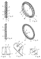
- Fig. 1
- die Vereinzelungstrommel in perspektivischer Darstellung,
- Fig. 2
- das für eine Saatreihe aus zwei Teilsegmenten zusammengesetzte Segment der Vereinzelungstrommel in der Ansicht von vorne,
- Fig. 3
- das für eine Saatreihe aus zwei Teilsegmenten zusammengesetzte Segment der Vereinzelungstrommel in perspektivischer Darstellung,
- Fig. 4
- ein Teilsegment der Vereinzelungstrommel in der Vorderansicht,
- Fig. 5
- ein Teilsegment in perspektivischer Darstellung,
- Fig. 6
- die Ausgestaltung der Verbindung der Perforation mit dem Trommelinnenraum in Seitenansicht,
- Fig. 7
- die Perforation in der Einzelheit VII aus Fig. 5,
- Fig. 8
- die Einzelheit der Perforation der Einzelheit VIII aus Fig. 3,
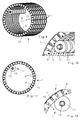
- Fig. 9
- die Trommel in Teilansicht und in perspektivischer Darstellung mit der Abdeckeinrichtung,
- Fig. 10
- die Anordnung der Abdeckeinrichtung im Innenraum der Vereinzelungstrommel in Teilansicht und vergrößerter Darstellung,
- Fig. 11
- die Anordnung der Abdeckeinrichtung im Innenraum der Vereinzelungstrommel in Seitenansicht und
- Fig. 12
- die Anordnung der Abdeckeinrichtung im Innenraum der Vereinzelungstrommel in Teilansicht und vergrößertem Maßstab.
- Die Vereinzelungstrommel 1 gemäß Fig. 1 ist in nicht dargestellter Weise drehbar in einem Gehäuse unterhalb eines Saatgutvorratsbehälters einer Einzelkornsämaschine angeordnet. Das Gehäuse bzw. der Saatgutvorratsbehälter weisen zwei voneinander beabstandete Seitenwände auf, die sich parallel zur Bewegungsrichtung der Trommel 1 und somit zumindest annähernd mit der Trommel 1 zusammenwirken. Die Vereinzelungstrommel 1 wird in bekannter Weise mittels eines Antriebes rotierend angetrieben. Die Vereinzelungstrommel 1 besteht aus einzelnen aus Teilsegmenten 2 bestehenden Segmenten 3, die zu einer Vereinzelungstrommel 1 zusammengesetzt sind. Mit in axialer Richtung wirksamen und nicht dargestellten Spannelementen werden diese einzelnen Segmente 3 zusammengehalten. Gemäß dem Ausführungsbeispiel nach Fig. 1 bis 5 weist die Vereinzelungstrommel 1 gegenüber der Trommeloberfläche 4 erhöht ringförmig umlaufende Vereinzelungsgürtel 5 auf, die im Querschnitt dachförmig ausgebildet sind. Wie insbesondere der Fig. 2 zu entnehmen ist, ist der Vereinzelungsgürtel 5 im Querschnitt etwa dreieckförmig ausgebildet. In den beiden Seitendachflächen 6 des Vereinzelungsgürtels 5 sind die Perforationslöcher 7 angeordnet. Die auf beiden Seiten 6 des Vereinzelungsgürtels 5 angeordneten Perforationslöcher 7 sind versetzt zueinander angeordnet, wie insbesondere der Fig. 2 zu entnehmen ist. Die Perforationslöcher 7 münden im mittleren Bereich des aus zwei Teilsegmenten 2 zusammengesetzten Vereinzelungssegmentes 3 in zu der Trommelinnenseite 8 offenen Verbindungskanälen 9. Die Ausgestaltung dieser Verbindungskanäle 9 wird weiter unten erläutert. Die Perforationen 7 werden mit einer Druckdifferenz beaufschlagt, welche von einem Gebläse, welches nicht dargestellt ist, erzeugt wird. Mittels dieses Gebläses ist für die Perforationen 7 eine Druckdifferenz zwischen dem Innenraum 8 der Vereinzelungstrommel 1 und dem Außenbereich 10 der Vereinzelungstrommel 1 zu erzeugen. Diese Druckdifferenz ist derart, so dass, wenn die Trommel 1 mit ihrer Außenseite 10 durch einen Saatgutvorrat geführt wird, dass sich an den Perforationen 7 auf der Außenseite 10 des Vereinzelungsgürtels 5 Samenkörner anlagern.
- Den Perforationen 7 eines Vereinzelungsgürtels 5 ist eine von der Vereinzelungstrommel 1 zu der Ablageeinrichtung, die beispielsweise als Säschar ausgebildet ist, führende Ausbringleitung in nicht dargestellter Weise zugeordnet. Durch die versetzte Anordnung der Perforationen 7 eines Vereinzelungsgürtels 5 wird ein größerer Abstand von Perforation 7 zu Perforation 7 geschaffen, so dass sich die Samenkörner in verbesserter Weise an den Perforationen 7 anlagern können, so dass eine verbesserte Vereinzelung als bei der Anordnung der Perforation in einer flächigen Trommel erreicht wird.
- Die Verbindungskanäle 9 der Perforationen 7 von der Außenseite 10 der Trommel 1 zur Innenseite 8 der Trommel 1 weisen von der Vereinzelungsseite der Perforation 7 bzw. der Trommel 1 abgewandten Seite 8 einen sich verjüngenden Querschnitt auf, so dass mit einem Druckunterbrechungseinrichtung, die auf der Innenseite 8 der Trommel 1 zur Anlage kommt, die Druckdifferenz sehr schnell unterbrochen wird, so dass sich die Samenkörner wesentlich definierter von den Perforationen 7 bzw. der Vereinzelungstrommel 1 lösen können und wesentlich vergleichmäßigter in die Ausbringleitung gelangen, so dass eine wesentlich bessere vergleichmäßigte Ablage des Saatgutes durch die Ablageeinrichtung der Einzelkornsämaschine gewährleistet ist. Den sich verjüngenden Querschnitt erkennt man in den Fig. 6 bis 8, wobei die Fig. 7 die Einzelheit VII aus der Fig. 5 und die Fig. 8 die Einzelheit VIII aus der Fig. 3 zeigt.
- Wie die Fig. 9-12 zeigen, ist im Innenraum der Vereinzelungstrommel 1 auf der der Vereinzelungsseite 10 des Vereinzelungsorgans abgewandten Seite 8 des Vereinzelungsorgans 1, die an die Perforation 7 anliegende Druckdifferenz zum Ablösen der Saatkörner unterbrechende Abdeckeinrichtung 11 in Form von auf einer Welle 12 angeordneten scheibenartigen Rolle 13 angeordnet. Die Trommel 1 weist im Bereich der Perforation 7 und des Vereinzelungsgürtels 5 eine Wandstärke von zumindest 3 mm auf, um den vorbeschriebenen Verlauf der die Außenseite der Perforation 7 mit der Innenseite 8 verbindenden Verbindungskanäle 9 beschriebene Querschnittsform zu ermöglichen, nämlich das die Querschnittsform der Perforierung 7 durch die Ausgestaltung der Verbindungskanäle 9 auf der Vereinzelungsseite 10 des Organs 1 unterschiedlich zu der Vereinzelungsseite 10 des Organs 1 ist. Der Querschnitt der Perforierung 7 ist auf der Vereinzelungsseite 10 des Organs 1 von Ausdehnung in und quer zur Drehrichtung des Organs 1 zumindest annähernd gleich. Die Ausdehnung des Querschnitts der Perforierung 7, der durch den Verbindungskanal 9 gebildet wird, ist auf der Vereinzelungsseite 10 der Vereinzelungstrommel 1 abgewandten Seite 8 der Trommel 1 in Drehrichtung wesentlich kleiner als in axialer Richtung der Trommel 1, wie die Fig. 6-8 zeigen. Die Fläche des Querschnittes der Perforierung 7 bzw. des Verbindungskanals 9 ist auf beiden Seiten der Wandung der Trommel 1 zumindest annähernd gleich groß. Hierbei ist zu beachten, dass die Fläche des Querschnittes der Perforierung 7 auf der Nichtvereinzelungsorgansseite 8 nicht kleiner als die Fläche der Perforierung 7 auf der Vereinzelungsseite 10 ist. Die Fläche des Querschnittes der Perforierung 7 bzw. des Verbindungskanals 9 weist auf der der Vereinzelungsseite 10 der Trommel 1 abgewandten Seite 8 einen rechteckigen Querschnitt auf.
Claims (5)
- Pneumatische Einzelkornsämaschine mit einem Saatgutvorratsbehälter und zumindest einer drehbar angeordneten Vereinzelungsorgan, wie Trommel, Riemen, Scheiben, in dessen Umfangsfläche kreisförmig angeordnete Perforationsreihen angebracht sind, einem Gebläse, mittels welchem eine Druckdifferenz zwischen dem Innenraum des Vereinzelungsorgans und dem Außenbereich des Vereinzelungsorgans erzeugbar ist, so dass, wenn das Vereinzelungsorgan durch den Saatgutvorrat geführt wird, sich an den Perforationen des perforierten Organs Samenkörner anlagern, wobei auf der Vereinzelungsseite des Vereinzelungsorgans abgewandten Seite des Vereinzelungsorgans, die an die Perforation anliegende Druckdifferenz zum Ablösen der Saatkörner unterbrechende Abdeckeinrichtung angeordnet ist, wobei die Abdeckeinrichtung im Bereich der Übergabe des Saatgutes von dem Organ in die Ausbringleitung angeordnet ist, dadurch gekennzeichnet, dass das Organ (1) im Bereich der Perforierung (7) der Perforationsreihen eine Wandstärke von zumindest 3 mm aufweist, dass die Querschnittsform der Perforierung (7) auf der Vereinzelungsseite (10) des Organs (1) unterschiedlich zu der der Vereinzelungsseite (10) abgewandten Seite (8) der Organs (1) ist.
- Einzelkornsämaschine nach Anspruch 1, dadurch gekennzeichnet, dass der Querschnitt der Perforierung (7) auf der Vereinzelungsseite (10) des Organs (1) von Ausdehnung in und quer zur Drehrichtung des Organs (1) zumindest annähernd gleich ist, dass die Ausdehnung des Querschnitts der Perforierung (7) auf der der Vereinzelungsseite (10) des Organs (1) abgewandten Seite (8) des Organs (1) in Drehrichtung des Organs (1) wesentlich kleiner als in axialer Richtung des Organs (1) ist.
- Einzelkornsämaschine nach einem oder mehreren der vorstehenden Ansprüche, dadurch gekennzeichnet, dass die Fläche des Querschnittes der Perforierung (7) auf beiden Seiten (8, 10) der Wandung des Organs (1) zumindest annähernd gleich groß ist.
- Einzelkornsämaschine nach einem oder mehreren der vorstehenden Ansprüche, dadurch gekennzeichnet, dass die Fläche des Querschnittes der Perforierung (7) auf der Nichtvereinzelungsorganseite (8) nicht kleiner als die Fläche der Perforierung (7) auf der Organvereinzelungsseite (10) ist.
- Einzelkornsämaschine nach einem oder mehreren der vorstehenden Ansprüche, dadurch gekennzeichnet, dass die Fläche des Querschnittes der Perforierung (7) auf der der Vereinzelungsseite (10) des Organs (1) abgewandten Seite (8) einen rechteckigen Querschnitt aufweist.
Applications Claiming Priority (1)
| Application Number | Priority Date | Filing Date | Title |
|---|---|---|---|
| DE102005038156A DE102005038156A1 (de) | 2005-08-12 | 2005-08-12 | Pneumatische Einzelkornsämaschine |
Publications (2)
| Publication Number | Publication Date |
|---|---|
| EP1752029A1 true EP1752029A1 (de) | 2007-02-14 |
| EP1752029B1 EP1752029B1 (de) | 2008-06-25 |
Family
ID=37433752
Family Applications (1)
| Application Number | Title | Priority Date | Filing Date |
|---|---|---|---|
| EP06016060A Not-in-force EP1752029B1 (de) | 2005-08-12 | 2006-08-02 | Pneumatische Einzelkornsämaschine |
Country Status (3)
| Country | Link |
|---|---|
| EP (1) | EP1752029B1 (de) |
| AT (1) | ATE398910T1 (de) |
| DE (2) | DE102005038156A1 (de) |
Cited By (3)
| Publication number | Priority date | Publication date | Assignee | Title |
|---|---|---|---|---|
| EP1842413A1 (de) * | 2006-04-05 | 2007-10-10 | Amazonen-Werke H. Dreyer GmbH & Co. KG | Pneumatische Einzelkornsämaschine |
| EP1842414A1 (de) * | 2006-04-05 | 2007-10-10 | Amazonen-Werke H. Dreyer GmbH & Co. KG | Einzelkornsämaschine |
| WO2008098652A3 (de) * | 2007-02-14 | 2009-10-22 | Amazonen-Werke H. Dreyer Gmbh & Co. Kg | Pneumatische einzelkornsämaschine |
Citations (5)
| Publication number | Priority date | Publication date | Assignee | Title |
|---|---|---|---|---|
| US3533535A (en) * | 1968-07-09 | 1970-10-13 | Aptek Ind Inc | High speed singulating device |
| DE2310979A1 (de) * | 1973-03-06 | 1974-09-12 | Becker Karl Masch | Zellenrad zum vereinzeln und verteilen von koernigem gut |
| DE2353597A1 (de) * | 1970-12-29 | 1975-05-07 | Becker Karl Masch | Zellenrad fuer einzelkornsaemaschinen |
| FR2641441A1 (fr) * | 1989-01-09 | 1990-07-13 | Techno Vert Sarl | Distributeur pneumatique pour semoirs multirangs |
| DE10140341B4 (de) | 2000-08-31 | 2004-05-06 | Société Industrielle de Constructions Agricoles et Métallurgiques | Vorrichtung zur Auswahl von Samenkörnern |
-
2005
- 2005-08-12 DE DE102005038156A patent/DE102005038156A1/de not_active Withdrawn
-
2006
- 2006-08-02 AT AT06016060T patent/ATE398910T1/de not_active IP Right Cessation
- 2006-08-02 EP EP06016060A patent/EP1752029B1/de not_active Not-in-force
- 2006-08-02 DE DE502006000972T patent/DE502006000972D1/de active Active
Patent Citations (5)
| Publication number | Priority date | Publication date | Assignee | Title |
|---|---|---|---|---|
| US3533535A (en) * | 1968-07-09 | 1970-10-13 | Aptek Ind Inc | High speed singulating device |
| DE2353597A1 (de) * | 1970-12-29 | 1975-05-07 | Becker Karl Masch | Zellenrad fuer einzelkornsaemaschinen |
| DE2310979A1 (de) * | 1973-03-06 | 1974-09-12 | Becker Karl Masch | Zellenrad zum vereinzeln und verteilen von koernigem gut |
| FR2641441A1 (fr) * | 1989-01-09 | 1990-07-13 | Techno Vert Sarl | Distributeur pneumatique pour semoirs multirangs |
| DE10140341B4 (de) | 2000-08-31 | 2004-05-06 | Société Industrielle de Constructions Agricoles et Métallurgiques | Vorrichtung zur Auswahl von Samenkörnern |
Cited By (3)
| Publication number | Priority date | Publication date | Assignee | Title |
|---|---|---|---|---|
| EP1842413A1 (de) * | 2006-04-05 | 2007-10-10 | Amazonen-Werke H. Dreyer GmbH & Co. KG | Pneumatische Einzelkornsämaschine |
| EP1842414A1 (de) * | 2006-04-05 | 2007-10-10 | Amazonen-Werke H. Dreyer GmbH & Co. KG | Einzelkornsämaschine |
| WO2008098652A3 (de) * | 2007-02-14 | 2009-10-22 | Amazonen-Werke H. Dreyer Gmbh & Co. Kg | Pneumatische einzelkornsämaschine |
Also Published As
| Publication number | Publication date |
|---|---|
| EP1752029B1 (de) | 2008-06-25 |
| DE502006000972D1 (de) | 2008-08-07 |
| DE102005038156A1 (de) | 2007-02-15 |
| ATE398910T1 (de) | 2008-07-15 |
Similar Documents
| Publication | Publication Date | Title |
|---|---|---|
| EP3057402B1 (de) | Säherz für einzelkornsämaschine | |
| EP3357319B1 (de) | Dosiervorrichtung | |
| EP2168417B1 (de) | Einzelkorndosiervorrichtung | |
| DE2310979A1 (de) | Zellenrad zum vereinzeln und verteilen von koernigem gut | |
| DE102014118390A1 (de) | Dreschtrommel | |
| EP2368415B1 (de) | Pneumatische Einzelkornsämaschine | |
| EP1752029B1 (de) | Pneumatische Einzelkornsämaschine | |
| EP0106299B1 (de) | Vereinzelungselement für pneumatische Einzelkornsämaschinen | |
| EP0657093A2 (de) | Säorgan | |
| EP1842413A1 (de) | Pneumatische Einzelkornsämaschine | |
| EP1752028B1 (de) | Pneumatische Einzelkornsämaschine | |
| DE102013100113B4 (de) | Abstreifer, Abstreifeinrichtung, Säherz | |
| EP3777502A1 (de) | Einzelkornsämaschine mit vereinzelungsvorrichtung | |
| EP1820382B1 (de) | Pneumatische Einzelkornsämaschine | |
| EP2117290B1 (de) | Pneumatische einzelkornsämaschine | |
| EP1961289B1 (de) | Landwirtschaftliche Arbeitsmaschine | |
| EP2559330A1 (de) | Pneumatische Einzelkornsämaschine | |
| DE102006012539A1 (de) | Pneumatische Einzelkornsämaschine | |
| DE10140341C5 (de) | Vorrichtung zur Auswahl von Samenkörnern | |
| EP2510769A1 (de) | Pneumatische Einzelkornsämaschine | |
| EP4008169B1 (de) | Landwirtschaftliche vereinzelungsvorrichtung zur vereinzelung von körnigem material | |
| EP1621059B1 (de) | Pneumatische Einzelkornsämaschine | |
| EP2225927B1 (de) | Pneumatische Einzelkornsämaschine | |
| DE102006016407A1 (de) | Pneumatische Einzelkornsämaschine | |
| EP2289297B1 (de) | Pneumatische Einzelkornsämaschine |
Legal Events
| Date | Code | Title | Description |
|---|---|---|---|
| PUAI | Public reference made under article 153(3) epc to a published international application that has entered the european phase |
Free format text: ORIGINAL CODE: 0009012 |
|
| AK | Designated contracting states |
Kind code of ref document: A1 Designated state(s): AT BE BG CH CY CZ DE DK EE ES FI FR GB GR HU IE IS IT LI LT LU LV MC NL PL PT RO SE SI SK TR |
|
| AX | Request for extension of the european patent |
Extension state: AL BA HR MK YU |
|
| 17P | Request for examination filed |
Effective date: 20070703 |
|
| AKX | Designation fees paid |
Designated state(s): AT BE BG CH CY CZ DE DK EE ES FI FR GB GR HU IE IS IT LI LT LU LV MC NL PL PT RO SE SI SK TR |
|
| GRAP | Despatch of communication of intention to grant a patent |
Free format text: ORIGINAL CODE: EPIDOSNIGR1 |
|
| GRAS | Grant fee paid |
Free format text: ORIGINAL CODE: EPIDOSNIGR3 |
|
| GRAA | (expected) grant |
Free format text: ORIGINAL CODE: 0009210 |
|
| AK | Designated contracting states |
Kind code of ref document: B1 Designated state(s): AT BE BG CH CY CZ DE DK EE ES FI FR GB GR HU IE IS IT LI LT LU LV MC NL PL PT RO SE SI SK TR |
|
| REG | Reference to a national code |
Ref country code: GB Ref legal event code: FG4D Free format text: NOT ENGLISH |
|
| REG | Reference to a national code |
Ref country code: CH Ref legal event code: EP |
|
| REF | Corresponds to: |
Ref document number: 502006000972 Country of ref document: DE Date of ref document: 20080807 Kind code of ref document: P |
|
| REG | Reference to a national code |
Ref country code: IE Ref legal event code: FG4D Free format text: LANGUAGE OF EP DOCUMENT: GERMAN |
|
| PG25 | Lapsed in a contracting state [announced via postgrant information from national office to epo] |
Ref country code: SI Free format text: LAPSE BECAUSE OF FAILURE TO SUBMIT A TRANSLATION OF THE DESCRIPTION OR TO PAY THE FEE WITHIN THE PRESCRIBED TIME-LIMIT Effective date: 20080625 Ref country code: FI Free format text: LAPSE BECAUSE OF FAILURE TO SUBMIT A TRANSLATION OF THE DESCRIPTION OR TO PAY THE FEE WITHIN THE PRESCRIBED TIME-LIMIT Effective date: 20080625 |
|
| PG25 | Lapsed in a contracting state [announced via postgrant information from national office to epo] |
Ref country code: PL Free format text: LAPSE BECAUSE OF FAILURE TO SUBMIT A TRANSLATION OF THE DESCRIPTION OR TO PAY THE FEE WITHIN THE PRESCRIBED TIME-LIMIT Effective date: 20080625 Ref country code: LV Free format text: LAPSE BECAUSE OF FAILURE TO SUBMIT A TRANSLATION OF THE DESCRIPTION OR TO PAY THE FEE WITHIN THE PRESCRIBED TIME-LIMIT Effective date: 20080625 |
|
| PG25 | Lapsed in a contracting state [announced via postgrant information from national office to epo] |
Ref country code: IS Free format text: LAPSE BECAUSE OF FAILURE TO SUBMIT A TRANSLATION OF THE DESCRIPTION OR TO PAY THE FEE WITHIN THE PRESCRIBED TIME-LIMIT Effective date: 20081025 Ref country code: SE Free format text: LAPSE BECAUSE OF FAILURE TO SUBMIT A TRANSLATION OF THE DESCRIPTION OR TO PAY THE FEE WITHIN THE PRESCRIBED TIME-LIMIT Effective date: 20080925 Ref country code: CZ Free format text: LAPSE BECAUSE OF FAILURE TO SUBMIT A TRANSLATION OF THE DESCRIPTION OR TO PAY THE FEE WITHIN THE PRESCRIBED TIME-LIMIT Effective date: 20080625 Ref country code: LT Free format text: LAPSE BECAUSE OF FAILURE TO SUBMIT A TRANSLATION OF THE DESCRIPTION OR TO PAY THE FEE WITHIN THE PRESCRIBED TIME-LIMIT Effective date: 20080625 |
|
| PG25 | Lapsed in a contracting state [announced via postgrant information from national office to epo] |
Ref country code: PT Free format text: LAPSE BECAUSE OF FAILURE TO SUBMIT A TRANSLATION OF THE DESCRIPTION OR TO PAY THE FEE WITHIN THE PRESCRIBED TIME-LIMIT Effective date: 20081125 Ref country code: RO Free format text: LAPSE BECAUSE OF FAILURE TO SUBMIT A TRANSLATION OF THE DESCRIPTION OR TO PAY THE FEE WITHIN THE PRESCRIBED TIME-LIMIT Effective date: 20080625 Ref country code: ES Free format text: LAPSE BECAUSE OF FAILURE TO SUBMIT A TRANSLATION OF THE DESCRIPTION OR TO PAY THE FEE WITHIN THE PRESCRIBED TIME-LIMIT Effective date: 20081006 Ref country code: SK Free format text: LAPSE BECAUSE OF FAILURE TO SUBMIT A TRANSLATION OF THE DESCRIPTION OR TO PAY THE FEE WITHIN THE PRESCRIBED TIME-LIMIT Effective date: 20080625 |
|
| REG | Reference to a national code |
Ref country code: IE Ref legal event code: FD4D |
|
| PG25 | Lapsed in a contracting state [announced via postgrant information from national office to epo] |
Ref country code: MC Free format text: LAPSE BECAUSE OF NON-PAYMENT OF DUE FEES Effective date: 20080831 |
|
| PG25 | Lapsed in a contracting state [announced via postgrant information from national office to epo] |
Ref country code: EE Free format text: LAPSE BECAUSE OF FAILURE TO SUBMIT A TRANSLATION OF THE DESCRIPTION OR TO PAY THE FEE WITHIN THE PRESCRIBED TIME-LIMIT Effective date: 20080625 Ref country code: IE Free format text: LAPSE BECAUSE OF FAILURE TO SUBMIT A TRANSLATION OF THE DESCRIPTION OR TO PAY THE FEE WITHIN THE PRESCRIBED TIME-LIMIT Effective date: 20080625 Ref country code: BG Free format text: LAPSE BECAUSE OF FAILURE TO SUBMIT A TRANSLATION OF THE DESCRIPTION OR TO PAY THE FEE WITHIN THE PRESCRIBED TIME-LIMIT Effective date: 20080925 Ref country code: DK Free format text: LAPSE BECAUSE OF FAILURE TO SUBMIT A TRANSLATION OF THE DESCRIPTION OR TO PAY THE FEE WITHIN THE PRESCRIBED TIME-LIMIT Effective date: 20080625 |
|
| PLBE | No opposition filed within time limit |
Free format text: ORIGINAL CODE: 0009261 |
|
| STAA | Information on the status of an ep patent application or granted ep patent |
Free format text: STATUS: NO OPPOSITION FILED WITHIN TIME LIMIT |
|
| 26N | No opposition filed |
Effective date: 20090326 |
|
| PG25 | Lapsed in a contracting state [announced via postgrant information from national office to epo] |
Ref country code: BE Free format text: LAPSE BECAUSE OF NON-PAYMENT OF DUE FEES Effective date: 20080831 |
|
| PG25 | Lapsed in a contracting state [announced via postgrant information from national office to epo] |
Ref country code: IT Free format text: LAPSE BECAUSE OF FAILURE TO SUBMIT A TRANSLATION OF THE DESCRIPTION OR TO PAY THE FEE WITHIN THE PRESCRIBED TIME-LIMIT Effective date: 20080625 |
|
| PG25 | Lapsed in a contracting state [announced via postgrant information from national office to epo] |
Ref country code: AT Free format text: LAPSE BECAUSE OF NON-PAYMENT OF DUE FEES Effective date: 20080802 |
|
| PG25 | Lapsed in a contracting state [announced via postgrant information from national office to epo] |
Ref country code: CY Free format text: LAPSE BECAUSE OF FAILURE TO SUBMIT A TRANSLATION OF THE DESCRIPTION OR TO PAY THE FEE WITHIN THE PRESCRIBED TIME-LIMIT Effective date: 20080625 Ref country code: LU Free format text: LAPSE BECAUSE OF NON-PAYMENT OF DUE FEES Effective date: 20080802 Ref country code: HU Free format text: LAPSE BECAUSE OF FAILURE TO SUBMIT A TRANSLATION OF THE DESCRIPTION OR TO PAY THE FEE WITHIN THE PRESCRIBED TIME-LIMIT Effective date: 20081226 |
|
| PG25 | Lapsed in a contracting state [announced via postgrant information from national office to epo] |
Ref country code: TR Free format text: LAPSE BECAUSE OF FAILURE TO SUBMIT A TRANSLATION OF THE DESCRIPTION OR TO PAY THE FEE WITHIN THE PRESCRIBED TIME-LIMIT Effective date: 20080625 |
|
| PG25 | Lapsed in a contracting state [announced via postgrant information from national office to epo] |
Ref country code: GR Free format text: LAPSE BECAUSE OF FAILURE TO SUBMIT A TRANSLATION OF THE DESCRIPTION OR TO PAY THE FEE WITHIN THE PRESCRIBED TIME-LIMIT Effective date: 20080926 |
|
| REG | Reference to a national code |
Ref country code: CH Ref legal event code: PL |
|
| GBPC | Gb: european patent ceased through non-payment of renewal fee |
Effective date: 20100802 |
|
| PG25 | Lapsed in a contracting state [announced via postgrant information from national office to epo] |
Ref country code: CH Free format text: LAPSE BECAUSE OF NON-PAYMENT OF DUE FEES Effective date: 20100831 Ref country code: LI Free format text: LAPSE BECAUSE OF NON-PAYMENT OF DUE FEES Effective date: 20100831 |
|
| PG25 | Lapsed in a contracting state [announced via postgrant information from national office to epo] |
Ref country code: GB Free format text: LAPSE BECAUSE OF NON-PAYMENT OF DUE FEES Effective date: 20100802 |
|
| REG | Reference to a national code |
Ref country code: FR Ref legal event code: ST Effective date: 20111202 |
|
| PG25 | Lapsed in a contracting state [announced via postgrant information from national office to epo] |
Ref country code: FR Free format text: LAPSE BECAUSE OF NON-PAYMENT OF DUE FEES Effective date: 20080901 |
|
| PGFP | Annual fee paid to national office [announced via postgrant information from national office to epo] |
Ref country code: NL Payment date: 20150809 Year of fee payment: 10 |
|
| PGFP | Annual fee paid to national office [announced via postgrant information from national office to epo] |
Ref country code: DE Payment date: 20150729 Year of fee payment: 10 |
|
| REG | Reference to a national code |
Ref country code: DE Ref legal event code: R119 Ref document number: 502006000972 Country of ref document: DE |
|
| REG | Reference to a national code |
Ref country code: NL Ref legal event code: MM Effective date: 20160901 |
|
| PG25 | Lapsed in a contracting state [announced via postgrant information from national office to epo] |
Ref country code: NL Free format text: LAPSE BECAUSE OF NON-PAYMENT OF DUE FEES Effective date: 20160901 |
|
| PG25 | Lapsed in a contracting state [announced via postgrant information from national office to epo] |
Ref country code: DE Free format text: LAPSE BECAUSE OF NON-PAYMENT OF DUE FEES Effective date: 20170301 |