EP1750260A1 - Disk autochanger - Google Patents
Disk autochanger Download PDFInfo
- Publication number
- EP1750260A1 EP1750260A1 EP05743527A EP05743527A EP1750260A1 EP 1750260 A1 EP1750260 A1 EP 1750260A1 EP 05743527 A EP05743527 A EP 05743527A EP 05743527 A EP05743527 A EP 05743527A EP 1750260 A1 EP1750260 A1 EP 1750260A1
- Authority
- EP
- European Patent Office
- Prior art keywords
- disc
- holding members
- disc holding
- autochanger
- elevator mechanism
- Prior art date
- Legal status (The legal status is an assumption and is not a legal conclusion. Google has not performed a legal analysis and makes no representation as to the accuracy of the status listed.)
- Withdrawn
Links
Images





Classifications
-
- G—PHYSICS
- G11—INFORMATION STORAGE
- G11B—INFORMATION STORAGE BASED ON RELATIVE MOVEMENT BETWEEN RECORD CARRIER AND TRANSDUCER
- G11B17/00—Guiding record carriers not specifically of filamentary or web form, or of supports therefor
- G11B17/02—Details
- G11B17/021—Selecting or spacing of record carriers for introducing the heads
-
- G—PHYSICS
- G11—INFORMATION STORAGE
- G11B—INFORMATION STORAGE BASED ON RELATIVE MOVEMENT BETWEEN RECORD CARRIER AND TRANSDUCER
- G11B17/00—Guiding record carriers not specifically of filamentary or web form, or of supports therefor
- G11B17/22—Guiding record carriers not specifically of filamentary or web form, or of supports therefor from random access magazine of disc records
- G11B17/221—Guiding record carriers not specifically of filamentary or web form, or of supports therefor from random access magazine of disc records with movable magazine
- G11B17/223—Guiding record carriers not specifically of filamentary or web form, or of supports therefor from random access magazine of disc records with movable magazine in a vertical direction
Definitions
- the present invention relates to a disc autochanger for automatically selecting a desired disc to be played back/recorded (played back or recorded on) from a plurality of stored CDs, MDs, or other discs and automatically transporting this to the playback/recording means.
- FIG. 12 is a view showing an outline of the Prior Art 1.
- the disc autochanger 1 shown in the Prior Art 1 ( Japanese Patent Publication (A) No. 2003-6974 ) is provided with a first disc holder 11 able to store a plurality of discs 2 and a second holder 12 able to store a plurality of discs 2.
- a playback/recording part 3 to play back (or record) above or below a disc 2-4 desired to be played back (or recorded on)
- discs 2 are transferred between the first disc holder 11 and second disc holder 12. Due to this, even during playback (recording), insertion of discs 2 becomes possible and therefore user friendliness is improved.
- the device can be made smaller in size.
- FIG. 13 is a view showing an outline of the Prior Art 2.
- the disc autochanger 1 shown in Prior Art 2 is a device forming a disc holder 11 able to store a plurality of discs 2 by members of the same configuration and able to separate them at any storage position.
- the disc holder 11 provided in the housing 13 of this disc autochanger 1 is formed by stacking a plurality of disc holding members 4 comprised of members of the same configuration. Each disc holding member 4 can store a disc 2.
- An elevator mechanism 6 raises or lowers the disc holder 11 as a whole to change its position. In this case, the separating member 14 pushes apart the adjoining disc holding members 4 in the disc holder 11 selected by the change in elevation to form a space enabling insertion of the playback/recording part 3.
- FIG. 13 An example of a disc autochanger able to eliminate these demerits is the disc autochanger 1 of the Prior Art 2 shown in FIG. 13. According to this disc autochanger 1, there is only one disc holder (11), so the above demerits are eliminated.
- the present invention in consideration of the above problems, has as its object the provision of a disc autochanger provided with a separating mechanism (14 etc. in FIG. 13) enabling a playback/recording part 3 to be inserted at the position of a disc holding member 4 holding a disc to be played back/recorded on and enabling the housing to be easily made small in size.
- FIG. 1 is a side view of a disc autochanger according to the present invention.
- FIG. 2 is a side view of a disc autochanger according to the Prior Art 2 (FIG. 13).
- the disc autochanger 1 is a disc autochanger provided with disc holding members able to hold a plurality of discs, a splitting member for insertion in said disc holding members so as to separate said disc holding members, and an elevator mechanism for raising or lowering said disc holding members to a position for insertion of said splitting member and for raising or lowering at least part of said disc holding members so as to enable insertion of a playback part, wherein referring to FIG.
- a splitting member 21 for splitting the stacked plurality of disc holding members 4 to separate them in the elevation direction at the disc holding member (for example 4-6) holding the disc to be played back/recorded on
- an elevator mechanism 6 for moving the plurality of disc holding members 4 in the elevation direction to move the disc holding member holding the disc to be played back/recorded on to a position for splitting by the splitting member 21 and splitting and enlarging the split so as to enable said playback/recording part 3 to be inserted are provided.
- the one characterizing the present invention is the (ii) splitting member 21.
- This splitting member 21 creates a space for insertion of the playback/recording part 3 among the stacked disc holding members 4, without employing the conventional large sized separating mechanism (for example, like the separating member 14), by simple hooking tabs for starting the creation of that space.
- Xr right indicates movement of the elevator mechanism 6 in the right direction
- Yd down indicates movement of the disc holding member 4-6 in the down direction.
- FIG. 2 showing the Prior Art 2
- the elevator mechanism 6 is used to make the disc holding member 4 of the disc to be played back/recorded on (for example 4-3) move to the position facing the separating member 14, then this separating member 14 proceeds in the right direction Xr, and the disc holding members 4-1 to 4-3 are lifted up together in the up direction Yu (up) to create the space for insertion of the playback/recording part 3.
- the disc autochanger 1 of FIG. 1 (the present invention) and the disc autochanger of FIG. 2 (Prior Art 2) will be compared by their plan views.
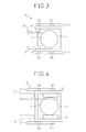
- FIG. 3 is a plan view of the disc autochanger according to the present invention
- FIG. 4 is a plan view of a disc autochanger according to the Prior Art 2 (FIG. 13).
- FIG. 3 and FIG. 4 are plan views in the state shown in FIG. 1 and FIG. 2.
- the splitting member 21 itself is comprised of small tabs, even including the small-sized drive mechanism (X-direction drive), the space occupied in the housing 13 by the splitting member does not pose almost any problem at all.
- the object of more greatly reducing the size of the disc autochanger 1 can be easily achieved.
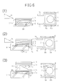
- FIGS. 5(1), (2), (3), and (4) are side views (centers) and plan views (right sides) showing the order of operation steps of Example 1 of the present invention. Further, FIGS. 6(1), (2), and (3) are side views and plan views showing the order of operation steps of the Prior Art 2 (FIG. 4). Note that to facilitate understanding, parts which are originally not visible are also drawn by solid lines.
- Example 1 the components essential for Example 1 are a detector 31, controller 32, and storage unit 33.
- the detector 31 shifts an elevator mechanism 6 in a direction (X) substantially perpendicularly intersecting the elevation direction (Y) and makes the disc holding members 4 (4-1 to 4-2) move in the elevation direction (Y) and detects at least one shift position for making that movement stop at a position facing a splitting member 21.
- the storage unit 33 stores the number of a disc to be played back/recorded on.
- controller (microprocessor) 32 controls the drive of the splitting member 21 and elevator mechanism 6 in accordance with the outputs of the storage unit 33 and detector 31.
- the disc autochanger 1 operates by the following steps:
- the elevator mechanism 6 is at the illustrated initial position, the splitting member 21 is at the illustrated position, and the disc holding members 4 (4-1 to 4-6) are at the overall illustrated highest positions.
- the splitting member 21 is at a fixed position (height) in the vertical direction (Y), but can be moved in the left-right direction (X) at that fixed position by a drive mechanism (not shown).
- the number of the disc to be played back/recorded on is designated by the user.
- the disc no. 4-6 corresponding to the disc 4-6 is designated. This disc no. 4-6 is stored in the storage unit 33.
- the controller (microprocessor) 32 makes the elevator mechanism 6 move in the right direction Xr by a drive mechanism (not shown) in accordance with a predetermined program. Due to this movement in the right direction Xr, projections 6b slidably engaging with inclined slits 6c of the elevator mechanism 6 are pushed down in the down direction Yd. Along with this, simultaneously, the table seat member 6a of the elevator mechanism 6 descends in the down direction Yd. Therefore, the disc holding members 4 (4-1 to 4-6) placed on the table seat member 6a descend as a whole (Yd).
- the sensor unit 31a of the fixed detector 31 constantly detects the shift position of the elevator mechanism 6 shifting in the left-right direction (X) and sends the detection results to the controller 32 at all times.
- This controller 32 holds a correspondence table between at least one shift position to be taken by each of the plurality of discs and the disc numbers. Details of this correspondence table will be explained later with reference to FIG. 7. According to the above example, the disc number is No. 4-6, so whether the stop position in the Yd direction to be taken in the case of the disc 4-6 (position where disc 4-6 faces splitting member 21) is reached is calculated from the above shift position detected by the sensor unit 3a of the detector 31.
- the controller 32 judges that the value showing the shift position detected by the above sensor unit 31a matches with the value corresponding to the above stop position assigned to the disk no. 4-6, the controller 32 stops the movement of the elevator mechanism 6 in the right direction Xr. Further, at this stop position, when pushing the splitting member 21 in the Xr direction of FIG. 5(3), it splits apart the disc holding member 4-6 and the adjoining disc holding member 4-5. After this, the disc holding members 4-5 to 4-1 remain constrained at that position by the splitting member 21.
- the controller 32 makes the elevator mechanism 6 move further in the right direction Xr.
- the disc holding members 4-1 to 4-5 and 4-6 are sufficiently separated and the space between the members is further enlarged.
- a first aspect of the disc autochanger of the present invention has disc holding members able to hold a plurality of discs, a table seat member for supporting said disc holding members, an elevator mechanism for raising and lowering said table seat member, and a splitting member inserted at a predetermined position of said disc holding members positioned by said elevator mechanism, said elevator mechanism lowering said table seat member after said splitting member is inserted into said disc holding members.
- a second aspect of the disc autochanger of the present invention has disc holding members able to hold a plurality of discs, a playback part able to be inserted into a separated space of said disk holding members, a table seat member for supporting said disc holding members, an elevator mechanism for raising or lowering said table seat member, and a splitting member inserted at a predetermined position of said disc holding members positioned by said elevator mechanism, said elevator mechanism lowering said table seat member after said splitting member is inserted into said disc holding members so as to split said disc holding members into disc holding members supported by said splitting member and disc holding members supported by said table seat member and said playback part playing back a disc in the formed separated space.
- the autochanger has a controller provided with a position detector for detecting a position of said table seat member and controlling said elevator mechanism based on said position detector so as to move said table seat member to a position corresponding to a desired separation position of the disc stockers.
- FIG. 1 The operation of the present invention (FIG. 1) explained with reference to FIG. 5 above differs considerably from the operation of the Prior Art 2 (FIG. 2). This is shown in FIGS. 6 in comparison with FIGS. 5.
- the separating member 14, elevator mechanism 6, and disc holding members 4 (4-1 to 4-6) are at the illustrated initial positions.
- the elevator mechanism 6 is made to move in the left direction X1 and due to this the disc holding members 4-1 to 4-6 as a whole are made to move in the up direction Yu.
- the boundary between the above disc holding member 4-3 in question and the adjoining disc holding member 4-4 matches with the position of the front end of the separating member 14.
- the separating member 14 is at a fixed position (height) in the vertical direction (Y), but can move in the left-right direction (X) at that fixed position by a drive mechanism (not shown).
- the separating member 14 in the state with the elevator mechanism 6 stopped, starts to move in the right direction Xr and lifts up the disc holding members 4-3 to 4-1 as a whole in the up direction (Yu) to create a large space.
- the playback/recording part 3 (FIG. 13) is inserted in that space.
- FIGS. 5 and FIGS. 6 both use common functional parts, but differ considerably in operating principle.
- the above-mentioned inherent merit is given of the "ease of reduction of size of the device".
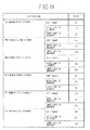
- FIG. 7 is a view of the correspondence table in the controller 32.
- the correspondence table 34 stored in for example a ROM in the controller 32 stores a predetermined correspondence between predetermined positions in the stacking direction (Y) where the disc holding members (4-1 to 4-6) should stop, that is, the "stop positions", and values of the predetermined shift positions.
- the left end shows five types of the above "stop positions”. Their meanings may be understood from the descriptions to the right:
- FIG. 8 is a view illustrating the relationship between the "stop positions" and "shift positions".
- the elevator mechanism 6 when, for example, at the "transfer", the elevator mechanism 6 has to be shifted in the right direction to make the projection 6b match with the "stop position” OD. That is, the elevator mechanism 6 is shifted to the right until the "shift position" SOD matches with the sensor unit 31a.
- the present invention is characterized in the step of splitting->separation by the splitting member 21.
- the projection 6b reaches the above "origin" constituted by the "stop position” 8A
- the elevator mechanism 6 has to stop being driven.
- FIG. 8 shows this step.
- the controller 32 stops driving the elevator mechanism 6 and then starts up the above-mentioned splitting operation by the splitting member 21.
- the detector 31 is comprised of a fixed base member 31b and a single sensor unit 31a provided at this fixed base member 31b and connected to the controller (microprocessor) 32.
- This single sensor unit 31a detects the above shift positions (S9A, S8A%) of the elevator mechanism 6.
- Example 2 of the present invention As the detector 31, one of another configuration is also possible. This is shown as Example 2 of the present invention.
- FIG. 9 is a view of the detector 31 employed in Example 2 of the present invention.
- the detector 31 in Example 2 is comprised of a base member 31b and a plurality of sensor units 31c, 31d, 31e, 31f, and 31g provided at this base member 31b and connected to the controller 32. These plurality of sensor units 31c to 31g are arranged at the above-mentioned shift positions corresponding to the predetermined positions (said "stop positions") in the elevation direction where the disc holding members should stop. This base member 31b can move to the "shift positions" corresponding to the individual disc holding members (4-1 to 4-6).
- FIGS. 9(A), (B), and (C) show the above "shift positions” corresponding to the time of the first member, the time of the second member, and the time of the fourth member (the time of the third member omitted) in the four-member version in the correspondence table 34 of FIG. 7.
- the interrelationship among the above five types of "stop positions" is immovable. The fact that even if the disc covered differs, this immovable interrelationship merely moves in parallel is taken note of.
- the detector 31 of Example 1 performs the detection processing shown in FIGS. 9(A), (B), and (C) by a single sensor unit 31a, so the processing load of the microprocessor forming the controller 32 becomes large.
- Example 2 judgment of the stop positions corresponding to the disc numbers becomes unnecessary, and the processing load of the above microprocessor becomes small.
- the hardware size becomes large. Note that if the above-mentioned sensor unit is a magnetic type, it is sufficient to provide small magnetic strips at the above shift positions, while if the sensor unit is an optical type, it is sufficient to provide small reflection films or open slits at the above shift positions.
- a gear-equipped slide-type variable resistor may be provided.
- the present invention provides two techniques.
- the first technique configures the storage unit 33 by a nonvolatile memory storing the disc numbers of the discs to be played back/recorded on. Since it is a nonvolatile memory, the disc numbers are held without regard as to whether the power is on or off.
- the second technique is applied to the case where the storage unit 33 is not such a nonvolatile memory.
- This storage unit 33 is comprised of a drive mechanism driven based on the output of the controller 32 and a sensor for detecting dynamic changes of this drive mechanism and is designed to calculate the number of the disc to be played back/recorded covered from the value of the output of this sensor. If illustrating this, the result becomes like in FIG. 10. However, the disc number first designated from the user side is directly written into the RAM in the microprocessor (32).
- FIG. 10 is a view showing the storage unit 33 of Example 3 of the present invention.
- the drive mechanism 35 is for example a motor.
- the rotational displacement of this motor changes the output value of the sensor 36.
- the output of this sensor 36 is an analog or digital value.
- the above motor (35) is designed to have correlation with the stop positions of the disc holding members 4-1 to 4-6.
- An example of the values of the output of the sensor 36 corresponding to the disc holding members (STOCKER) is shown in FIG. 11.
- FIG. 11 is a view showing an example of the values of the output from the sensor 36 in a storage unit 33 of the type of FIG. 10.
- This figure shows an example of a six-member version. This shows the judgment value providing a hint as to which stocker was to be played back/recorded right before the power turned off and the original target value for each of the first member (FIRST STOCKER) to sixth member (SIXTH STOKER) of the disc holding members 4-1 to 4-6.
- the judgment values are given a range of an upper limit and lower limit.
- the microprocessor (32) judges which range the output value of the sensor 36 is in and resets the target value based on this when the power again turns on.
- the invention can be applied to an audio system, computer system, etc. required to store a plurality of disc shaped data storage media in a single housing and load, play back/record on, and eject any one automatically and is particularly beneficial in reducing the size of said system.
Landscapes
- Automatic Disk Changers (AREA)
Abstract
Description
- The present invention relates to a disc autochanger for automatically selecting a desired disc to be played back/recorded (played back or recorded on) from a plurality of stored CDs, MDs, or other discs and automatically transporting this to the playback/recording means.
- As an already known disc autochanger, for example, there are the following [Patent Document 1], [Patent Document 2], etc. These Prior Art 1 [Patent Document 1] and Prior Art 2 [Patent Document 2] are summarized below:
- FIG. 12 is a view showing an outline of the Prior
Art 1. - In the figure, the
disc autochanger 1 shown in the Prior Art 1 (Japanese Patent Publication (A) No. 2003-6974 first disc holder 11 able to store a plurality ofdiscs 2 and asecond holder 12 able to store a plurality ofdiscs 2. To secure the space required for a playback/recordingpart 3 to play back (or record) above or below a disc 2-4 desired to be played back (or recorded on),discs 2 are transferred between thefirst disc holder 11 andsecond disc holder 12. Due to this, even during playback (recording), insertion ofdiscs 2 becomes possible and therefore user friendliness is improved. Further, by making the discs 2 (2-1, 2-2, and 2-3) stored in thefirst disc holder 11 and the discs 2 (2-5) stored in thesecond disc holder 12 anddisc 2 being played back (2-4) at least partially overlap on a projection plane, the device can be made smaller in size. - Note that the reference numerals 4 (4-1 to 4-6) in the figure show the disc holding members, while 5 shows a load/eject mechanism of discs 2 (in the figure, 2-6).
- Next, looking at the above-mentioned Prior
Art 2, FIG. 13 is a view showing an outline of the PriorArt 2. - In the figure, the
disc autochanger 1 shown in Prior Art 2 (Japanese Patent Publication (A) No. 2000-48464 disc holder 11 able to store a plurality ofdiscs 2 by members of the same configuration and able to separate them at any storage position. - The
disc holder 11 provided in thehousing 13 of thisdisc autochanger 1 is formed by stacking a plurality ofdisc holding members 4 comprised of members of the same configuration. Eachdisc holding member 4 can store adisc 2. Anelevator mechanism 6 raises or lowers thedisc holder 11 as a whole to change its position. In this case, the separatingmember 14 pushes apart the adjoiningdisc holding members 4 in thedisc holder 11 selected by the change in elevation to form a space enabling insertion of the playback/recording part 3. -
- [Patent Document 1]
Japanese Patent Publication (A) No. 2003-6974 - [Patent Document 2]
Japanese Patent Publication (A) No. 2000-48464 - According to the disc autochanger 1 (FIG. 12) of the above Prior
Art 1, two disc holders, that is, afirst disc holder 11 andsecond disc holder 12, are introduced. For this reason, this has the demerits that thehousing 13 ends up becoming larger in size overall and further the cost is increased. - An example of a disc autochanger able to eliminate these demerits is the
disc autochanger 1 of the PriorArt 2 shown in FIG. 13. According to thisdisc autochanger 1, there is only one disc holder (11), so the above demerits are eliminated. - However, according to the disc autochanger 1 (FIG. 13) of this Prior
Art 2, in addition to theelevator mechanism 6, the separatingmember 14 becomes an essential component. For this reason, there is the problem that it is difficult to make thehousing 13 as a whole remarkably smaller in size. Note that this problem will be explained in detail later with reference to FIG. 3 and FIG. 4. - Therefore, the present invention, in consideration of the above problems, has as its object the provision of a disc autochanger provided with a separating mechanism (14 etc. in FIG. 13) enabling a playback/
recording part 3 to be inserted at the position of adisc holding member 4 holding a disc to be played back/recorded on and enabling the housing to be easily made small in size. - FIG. 1 is a side view of a disc autochanger according to the present invention. Further, FIG. 2 is a side view of a disc autochanger according to the Prior Art 2 (FIG. 13).
- The
disc autochanger 1 according to the present invention is a disc autochanger provided with disc holding members able to hold a plurality of discs, a splitting member for insertion in said disc holding members so as to separate said disc holding members, and an elevator mechanism for raising or lowering said disc holding members to a position for insertion of said splitting member and for raising or lowering at least part of said disc holding members so as to enable insertion of a playback part, wherein
referring to FIG. 1, at least (i) a plurality of disc holding members 4 (4-1 to 4-6) able to hold stacked the plurality ofdiscs 2, (ii) a splittingmember 21 for splitting the stacked plurality ofdisc holding members 4 to separate them in the elevation direction at the disc holding member (for example 4-6) holding the disc to be played back/recorded on, and (iii) anelevator mechanism 6 for moving the plurality ofdisc holding members 4 in the elevation direction to move the disc holding member holding the disc to be played back/recorded on to a position for splitting by the splittingmember 21 and splitting and enlarging the split so as to enable said playback/recording part 3 to be inserted are provided. - Among the above components (i) to (iii), the one characterizing the present invention is the (ii) splitting
member 21. This splittingmember 21 creates a space for insertion of the playback/recordingpart 3 among the stackeddisc holding members 4, without employing the conventional large sized separating mechanism (for example, like the separating member 14), by simple hooking tabs for starting the creation of that space. Note that in FIG. 1, Xr (right) indicates movement of theelevator mechanism 6 in the right direction, while Yd (down) indicates movement of the disc holding member 4-6 in the down direction. - On the other hand, referring to FIG. 2 showing the Prior
Art 2, in thisdisc autochanger 1, in order to create a space for insertion of the playback/recordingpart 3 among the stacked disc holding members 4 (4-1 to 4-6), theelevator mechanism 6 is used to make thedisc holding member 4 of the disc to be played back/recorded on (for example 4-3) move to the position facing the separatingmember 14, then this separatingmember 14 proceeds in the right direction Xr, and the disc holding members 4-1 to 4-3 are lifted up together in the up direction Yu (up) to create the space for insertion of the playback/recording part 3. - Here, the
disc autochanger 1 of FIG. 1 (the present invention) and the disc autochanger of FIG. 2 (Prior Art 2) will be compared by their plan views. - FIG. 3 is a plan view of the disc autochanger according to the present invention, while FIG. 4 is a plan view of a disc autochanger according to the Prior Art 2 (FIG. 13).
- Note that FIG. 3 and FIG. 4 are plan views in the state shown in FIG. 1 and FIG. 2.
- Comparing FIG. 3 and FIG. 4, both have
similar components - However, if comparing the splitting member 21 (FIG. 3) and the separating member 14 (FIG. 4), a large difference is seen between the two. This relates to the total strokes (S) of these members in the
housing 13. - That is, compared with the total stroke S2 (14'←→14) of FIG. 4 of the separating
member 14 in the PriorArt 2, the total stroke S1 (21'←→21) of FIG. 3 of the splittingmember 21 in the present invention is much different. Of course, S1<<S2. - As a result, there is no longer any restriction on space in laying out the various components to be placed in the
housing 13 and therefore it becomes possible to freely select the layout of the components. Further, since the splittingmember 21 itself is comprised of small tabs, even including the small-sized drive mechanism (X-direction drive), the space occupied in thehousing 13 by the splitting member does not pose almost any problem at all. - Accordingly, the object of more greatly reducing the size of the
disc autochanger 1 can be easily achieved. -
- FIG. 1 is a side view of a disc autochanger according to the present invention.
- FIG. 2 is a side view of a disc autochanger according to the Prior Art 2 (FIG. 13).
- FIG. 3 is a plan view of a disc autochanger according to the present invention.
- FIG. 4 is a plan view of a disc autochanger according to the Prior Art 2 (FIG. 13).
- FIGS. 5(1) to (4) are side views and plan views indicating the order of the operation steps of Example 1 of the present invention.
- FIGS. 6(1) to (3) are side views and plan views indicating the order of operation steps of the Prior Art 2 (FIG. 2).
- FIG. 7 is a view showing a correspondence table in a controller.
- FIG. 8 is a view illustrating the relationship between the "stop positions" and "shift positions".
- FIG. 9(A) to (C) are views showing a detector employed in Example 2 of the present invention.
- FIG. 10 is a view of a storage unit employed in Example 3 of the present invention.
- FIG. 11 is a view of an example of the value of output from a sensor in the storage unit shown in FIG. 10.
- FIG. 12 is a view showing an outline of the Prior
Art 1. - FIG. 13 is a view showing an outline of the Prior
Art 2. - FIGS. 5(1), (2), (3), and (4) are side views (centers) and plan views (right sides) showing the order of operation steps of Example 1 of the present invention. Further, FIGS. 6(1), (2), and (3) are side views and plan views showing the order of operation steps of the Prior Art 2 (FIG. 4). Note that to facilitate understanding, parts which are originally not visible are also drawn by solid lines.
- First, referring to FIG. 5, the components essential for Example 1 are a
detector 31,controller 32, andstorage unit 33. - The
detector 31 shifts anelevator mechanism 6 in a direction (X) substantially perpendicularly intersecting the elevation direction (Y) and makes the disc holding members 4 (4-1 to 4-2) move in the elevation direction (Y) and detects at least one shift position for making that movement stop at a position facing a splittingmember 21. - The
storage unit 33 stores the number of a disc to be played back/recorded on. - Further, the controller (microprocessor) 32 controls the drive of the splitting
member 21 andelevator mechanism 6 in accordance with the outputs of thestorage unit 33 anddetector 31. - Due to the above explained parts (3, 6, 21, 31, 32, and 33), the
disc autochanger 1 operates by the following steps: - (1) In the first step, the
elevator mechanism 6 is at the illustrated initial position, the splittingmember 21 is at the illustrated position, and the disc holding members 4 (4-1 to 4-6) are at the overall illustrated highest positions. Note that the splittingmember 21 is at a fixed position (height) in the vertical direction (Y), but can be moved in the left-right direction (X) at that fixed position by a drive mechanism (not shown). - Here, next, assume that the number of the disc to be played back/recorded on is designated by the user. In the example of this figure, assume that the disc no. 4-6 corresponding to the disc 4-6 is designated. This disc no. 4-6 is stored in the
storage unit 33. - (2) In the second step, the controller (microprocessor) 32 makes the
elevator mechanism 6 move in the right direction Xr by a drive mechanism (not shown) in accordance with a predetermined program. Due to this movement in the right direction Xr,projections 6b slidably engaging withinclined slits 6c of theelevator mechanism 6 are pushed down in the down direction Yd. Along with this, simultaneously, thetable seat member 6a of theelevator mechanism 6 descends in the down direction Yd. Therefore, the disc holding members 4 (4-1 to 4-6) placed on thetable seat member 6a descend as a whole (Yd). - In this case, the
sensor unit 31a of the fixeddetector 31 constantly detects the shift position of theelevator mechanism 6 shifting in the left-right direction (X) and sends the detection results to thecontroller 32 at all times. - This
controller 32 holds a correspondence table between at least one shift position to be taken by each of the plurality of discs and the disc numbers. Details of this correspondence table will be explained later with reference to FIG. 7. According to the above example, the disc number is No. 4-6, so whether the stop position in the Yd direction to be taken in the case of the disc 4-6 (position where disc 4-6 faces splitting member 21) is reached is calculated from the above shift position detected by the sensor unit 3a of thedetector 31. - (3) In the third step, when the
controller 32 judges that the value showing the shift position detected by theabove sensor unit 31a matches with the value corresponding to the above stop position assigned to the disk no. 4-6, thecontroller 32 stops the movement of theelevator mechanism 6 in the right direction Xr. Further, at this stop position, when pushing the splittingmember 21 in the Xr direction of FIG. 5(3), it splits apart the disc holding member 4-6 and the adjoining disc holding member 4-5. After this, the disc holding members 4-5 to 4-1 remain constrained at that position by the splittingmember 21. - (4) In the fourth step, leaving the disc holding members 4-1 to 4-5 at the position of the third step, the
controller 32 makes theelevator mechanism 6 move further in the right direction Xr. Here, the disc holding members 4-1 to 4-5 and 4-6 are sufficiently separated and the space between the members is further enlarged. - Utilizing this enlarged space, the playback/
recording part 3 shown in FIG. 13 starts to function. - In the above way, a first aspect of the disc autochanger of the present invention has disc holding members able to hold a plurality of discs, a table seat member for supporting said disc holding members, an elevator mechanism for raising and lowering said table seat member, and a splitting member inserted at a predetermined position of said disc holding members positioned by said elevator mechanism, said elevator mechanism lowering said table seat member after said splitting member is inserted into said disc holding members.
- Further, a second aspect of the disc autochanger of the present invention has disc holding members able to hold a plurality of discs, a playback part able to be inserted into a separated space of said disk holding members, a table seat member for supporting said disc holding members, an elevator mechanism for raising or lowering said table seat member, and a splitting member inserted at a predetermined position of said disc holding members positioned by said elevator mechanism, said elevator mechanism lowering said table seat member after said splitting member is inserted into said disc holding members so as to split said disc holding members into disc holding members supported by said splitting member and disc holding members supported by said table seat member and said playback part playing back a disc in the formed separated space.
- Further, the autochanger has a controller provided with a position detector for detecting a position of said table seat member and controlling said elevator mechanism based on said position detector so as to move said table seat member to a position corresponding to a desired separation position of the disc stockers.
- The operation of the present invention (FIG. 1) explained with reference to FIG. 5 above differs considerably from the operation of the Prior Art 2 (FIG. 2). This is shown in FIGS. 6 in comparison with FIGS. 5.
- Referring to FIGS. 6,
(1) at the first step, the separatingmember 14,elevator mechanism 6, and disc holding members 4 (4-1 to 4-6) are at the illustrated initial positions. - Note that in the example of these figures, assume that the disc (No. 4-3) held at the disc holding member 4-3 is the disc to be played back/recorded on.
- (2) At the second step, the
elevator mechanism 6 is made to move in the left direction X1 and due to this the disc holding members 4-1 to 4-6 as a whole are made to move in the up direction Yu. - (3) At the third step, due to the movement of the disc holding members 4-1 to 4-6 as a whole in the up direction (Yu), the boundary between the above disc holding member 4-3 in question and the adjoining disc holding member 4-4 matches with the position of the front end of the separating
member 14. Note that the separatingmember 14 is at a fixed position (height) in the vertical direction (Y), but can move in the left-right direction (X) at that fixed position by a drive mechanism (not shown). - Then, the separating
member 14, in the state with theelevator mechanism 6 stopped, starts to move in the right direction Xr and lifts up the disc holding members 4-3 to 4-1 as a whole in the up direction (Yu) to create a large space. The playback/recording part 3 (FIG. 13) is inserted in that space. - As clear from the comparison of the above-mentioned FIGS. 5 and FIGS. 6, the present invention (FIG. 1) and the Prior Art 2 (FIG. 2) both use common functional parts, but differ considerably in operating principle. As a result, according to the present invention, the above-mentioned inherent merit is given of the "ease of reduction of size of the device".
- Here, the above-mentioned
detector 31 and the already explained correspondence table in thecontroller 32 will be explained in further detail. - FIG. 7 is a view of the correspondence table in the
controller 32. - In the figure, the correspondence table 34 stored in for example a ROM in the
controller 32 stores a predetermined correspondence between predetermined positions in the stacking direction (Y) where the disc holding members (4-1 to 4-6) should stop, that is, the "stop positions", and values of the predetermined shift positions. - Referring to FIG. 7, the left end shows five types of the above "stop positions". Their meanings may be understood from the descriptions to the right:
-
- Stop position: DETECTING POSITION
- Load/eject preparation: LOAD/EJECT (load/eject mechanism 5)
- Origin: HOME POSITION (splitting position 21)
- Drive through: SLIDE DRIVE UNIT (playback/recording part 3)
- Turntable: PLACE DISC
- Transfer: TRANSFER DISCS
- When at the "load/eject preparation", the "stop position" = 9A
- When at the "origin", the "stop position" = 8A
- When at the "drive through", the "stop position" = 62
- When at the "turntable", the "stop position" = 4F
- When at the "transfer", the "stop position" = 0D. Note that the
right end - The relationship between the above "stop positions" and the already explained "shift positions" of the
sensor unit 31a at the step of FIG. 5(3) may be expressed as shown in FIG. 8. - FIG. 8 is a view illustrating the relationship between the "stop positions" and "shift positions".
- In the figure, when, for example, at the above "load/eject preparation", the
elevator mechanism 6 has to be shifted to the left direction to make theprojection 6b match with the "stop position" 9A. That is, theelevator mechanism 6 is shifted to the left until the "shift position" S9A matches with thesensor unit 31a. - Further, when, for example, at the "transfer", the
elevator mechanism 6 has to be shifted in the right direction to make theprojection 6b match with the "stop position" OD. That is, theelevator mechanism 6 is shifted to the right until the "shift position" SOD matches with thesensor unit 31a. - The present invention is characterized in the step of splitting->separation by the splitting
member 21. In this case, when theprojection 6b reaches the above "origin" constituted by the "stop position" 8A, theelevator mechanism 6 has to stop being driven. FIG. 8 shows this step. When detecting that thesensor unit 31a matches with the "shift position" S8A, thecontroller 32 stops driving theelevator mechanism 6 and then starts up the above-mentioned splitting operation by the splittingmember 21. - Therefore, in Example 1 shown in FIG. 5, the
detector 31 is comprised of a fixedbase member 31b and asingle sensor unit 31a provided at this fixedbase member 31b and connected to the controller (microprocessor) 32. Thissingle sensor unit 31a detects the above shift positions (S9A, S8A...) of theelevator mechanism 6. - As the
detector 31, one of another configuration is also possible. This is shown as Example 2 of the present invention. - FIG. 9 is a view of the
detector 31 employed in Example 2 of the present invention. - The
detector 31 in Example 2 is comprised of abase member 31b and a plurality ofsensor units base member 31b and connected to thecontroller 32. These plurality ofsensor units 31c to 31g are arranged at the above-mentioned shift positions corresponding to the predetermined positions (said "stop positions") in the elevation direction where the disc holding members should stop. Thisbase member 31b can move to the "shift positions" corresponding to the individual disc holding members (4-1 to 4-6). - Note that FIGS. 9(A), (B), and (C) show the above "shift positions" corresponding to the time of the first member, the time of the second member, and the time of the fourth member (the time of the third member omitted) in the four-member version in the correspondence table 34 of FIG. 7. The interrelationship among the above five types of "stop positions" is immovable. The fact that even if the disc covered differs, this immovable interrelationship merely moves in parallel is taken note of. The
detector 31 of Example 1 performs the detection processing shown in FIGS. 9(A), (B), and (C) by asingle sensor unit 31a, so the processing load of the microprocessor forming thecontroller 32 becomes large. On this point, in Example 2, judgment of the stop positions corresponding to the disc numbers becomes unnecessary, and the processing load of the above microprocessor becomes small. However, the hardware size becomes large. Note that if the above-mentioned sensor unit is a magnetic type, it is sufficient to provide small magnetic strips at the above shift positions, while if the sensor unit is an optical type, it is sufficient to provide small reflection films or open slits at the above shift positions. Alternatively, a gear-equipped slide-type variable resistor may be provided. - However, both in the case of Example 1 and in the case of Example 2, the detection results read from the sensor units (31a and 31c to 31g) are recorded once in the RAM in the above controller (microprocessor) 32.
- For this reason, when the power of the
disc autochanger 1 is turned off for some reason or another (either by human hand or by accident), said microprocessor is reset and the stored content of the above RAM ends up being completely lost. - This being so, when the power is again turned on, at the time of this restart, the device does not know at all which disk it was able to process right before. Therefore, after this, either a mistaken operation will be caused or no operation at all becomes possible and the current state cannot be restored.
- To deal with this situation, the present invention provides two techniques.
- The first technique configures the
storage unit 33 by a nonvolatile memory storing the disc numbers of the discs to be played back/recorded on. Since it is a nonvolatile memory, the disc numbers are held without regard as to whether the power is on or off. - The second technique is applied to the case where the
storage unit 33 is not such a nonvolatile memory. Thisstorage unit 33 is comprised of a drive mechanism driven based on the output of thecontroller 32 and a sensor for detecting dynamic changes of this drive mechanism and is designed to calculate the number of the disc to be played back/recorded covered from the value of the output of this sensor. If illustrating this, the result becomes like in FIG. 10. However, the disc number first designated from the user side is directly written into the RAM in the microprocessor (32). - FIG. 10 is a view showing the
storage unit 33 of Example 3 of the present invention. - In the figure, the above-mentioned drive mechanism and sensor are shown by the
reference numerals - The
drive mechanism 35 is for example a motor. The rotational displacement of this motor changes the output value of thesensor 36. The output of thissensor 36 is an analog or digital value. - More specifically, the above motor (35) is designed to have correlation with the stop positions of the disc holding members 4-1 to 4-6. An example of the values of the output of the
sensor 36 corresponding to the disc holding members (STOCKER) is shown in FIG. 11. - FIG. 11 is a view showing an example of the values of the output from the
sensor 36 in astorage unit 33 of the type of FIG. 10. - This figure shows an example of a six-member version. This shows the judgment value providing a hint as to which stocker was to be played back/recorded right before the power turned off and the original target value for each of the first member (FIRST STOCKER) to sixth member (SIXTH STOKER) of the disc holding members 4-1 to 4-6. The judgment values are given a range of an upper limit and lower limit. The microprocessor (32) judges which range the output value of the
sensor 36 is in and resets the target value based on this when the power again turns on. - The invention can be applied to an audio system, computer system, etc. required to store a plurality of disc shaped data storage media in a single housing and load, play back/record on, and eject any one automatically and is particularly beneficial in reducing the size of said system.
Claims (11)
- A disc autochanger comprising:disc holding members able to hold a plurality of discs,a splitting member inserted in said disc holding members for splitting said disc holding members, andan elevator mechanism for raising or lowering said disc holding members to a position for insertion of said splitting member and for raising or lowering at least part of said disc holding members to enable insertion of a playback part.
- A disc autochanger as set forth in claim 1, further provided with a detector for making said elevator mechanism shift in an elevation direction to move said disc holding members and detecting at least one shift position for making that movement stop at a position facing said splitting member, a storage unit for storing a number of a disk to be played back, and a controller for controlling the drive of said splitting member and said elevator mechanism in accordance with outputs of said storage unit and said detector.
- A disc autochanger as set forth in claim 2, wherein said controller holds a correspondence table between at least one shift position to be taken by each of said plurality of discs and said disc numbers.
- A disc autochanger as set forth in claim 2, wherein said detector is comprised of a fixed base member and sensor units provided at said fixed base member and connected to said controller, and said sensor units detect said shift positions of said elevator mechanism.
- A disc autochanger as set forth in claim 2, wherein said detector is comprised of a base member and sensor units provided at said base member and connected to said controller, said sensor units are arranged at shift positions corresponding to predetermined positions of said elevation direction at which said disc holding member should stop, and said base member can move to the shift positions corresponding to said disc holding members.
- A disc autochanger as set forth in claim 2, wherein said storage unit is comprised of a nonvolatile memory storing the number of a disc to be played back.
- A disc autochanger as set forth in claim 2, wherein said storage unit is comprised of a drive mechanism driven based on the output of said controller and a sensor detecting dynamic changes of said drive mechanism and calculates the number of the disc to be played back from the value of the output of said sensor.
- A disc autochanger as set forth in any one of claims 1 to 7, wherein said disc autochanger records on the discs.
- A disc autochanger having disc holding members able to hold a plurality of discs, a table seat member for supporting said disc holding members, an elevator mechanism for raising or lowering said table seat member, and a splitting member inserted at a predetermined position of said disc holding members positioned by said elevator mechanism, said elevator mechanism lowering said table seat member after said splitting member is inserted into said disc holding members.
- A disc autochanger having disc holding members able to hold a plurality of discs, a playback part able to be inserted into a separated space of said disk holding members, a table seat member for supporting said disc holding members, an elevator mechanism for raising or lowering said table seat member, and a splitting member inserted at a predetermined position of said disc holding members positioned by said elevator mechanism, said elevator mechanism lowering said table seat member after said splitting member is inserted into said disc holding members so as to separate said disc holding members into disc holding members supported by said splitting member and disc holding members supported by said table seat member and said playback part playing back a disc in the formed separated space.
- A disc autochanger as set forth in claim 9 or 10, having a controller provided with a position detector for detecting a position of said table seat member and controlling said elevator mechanism based on said position detector so as to move said table seat member to a position corresponding to a desired separation position of disc stockers.
Applications Claiming Priority (2)
| Application Number | Priority Date | Filing Date | Title |
|---|---|---|---|
| JP2004149359A JP4493400B2 (en) | 2004-05-19 | 2004-05-19 | Disc auto changer |
| PCT/JP2005/009502 WO2005112027A1 (en) | 2004-05-19 | 2005-05-18 | Disk autochanger |
Publications (2)
| Publication Number | Publication Date |
|---|---|
| EP1750260A1 true EP1750260A1 (en) | 2007-02-07 |
| EP1750260A4 EP1750260A4 (en) | 2008-12-10 |
Family
ID=35394396
Family Applications (1)
| Application Number | Title | Priority Date | Filing Date |
|---|---|---|---|
| EP05743527A Withdrawn EP1750260A4 (en) | 2004-05-19 | 2005-05-18 | Disk autochanger |
Country Status (5)
| Country | Link |
|---|---|
| US (1) | US7565666B2 (en) |
| EP (1) | EP1750260A4 (en) |
| JP (1) | JP4493400B2 (en) |
| CN (1) | CN100559484C (en) |
| WO (1) | WO2005112027A1 (en) |
Families Citing this family (2)
| Publication number | Priority date | Publication date | Assignee | Title |
|---|---|---|---|---|
| CN101751955B (en) * | 2008-12-05 | 2011-07-20 | 谷林电器(深圳)有限公司 | Compact disc player capable of monitoring compact disc states |
| JP6107456B2 (en) * | 2013-06-14 | 2017-04-05 | 富士通株式会社 | Configuration requirement creation program, configuration requirement creation device, and configuration requirement creation method |
Family Cites Families (23)
| Publication number | Priority date | Publication date | Assignee | Title |
|---|---|---|---|---|
| JP2620146B2 (en) | 1989-12-06 | 1997-06-11 | クラリオン株式会社 | Disc-shaped recording medium playback device |
| JPH0461080A (en) | 1990-06-29 | 1992-02-27 | Victor Co Of Japan Ltd | Disk cartridge and disk recording and reproducing device |
| CA2073400A1 (en) * | 1991-11-08 | 1993-05-09 | Masayuki Hoshi | Disk player |
| JP2679539B2 (en) | 1992-07-16 | 1997-11-19 | 日本ビクター株式会社 | Automatic disc playing device |
| US6075758A (en) * | 1993-12-20 | 2000-06-13 | Wu; Qian | Selector mechanism for multiple compact disks and method of selection |
| JPH07282526A (en) | 1994-04-11 | 1995-10-27 | Matsushita Electric Ind Co Ltd | Disc playing device |
| US5818723A (en) * | 1994-12-22 | 1998-10-06 | International Business Machines Corporation | Quick access data storage library with backup capability |
| KR0160731B1 (en) * | 1995-10-31 | 1999-01-15 | 김광호 | Disk writing reproducing device |
| US5870245A (en) * | 1995-11-09 | 1999-02-09 | Overland Data, Inc. | Modular cabinet for data storage media and drives |
| NL1002954C2 (en) * | 1996-04-26 | 1997-10-28 | Chess Engineering B V | Device for storing and selectively playing disc-shaped information carriers. |
| CN1088889C (en) * | 1996-06-13 | 2002-08-07 | 富士通坦株式会社 | Reproduction/recording apparatus and housing apparatus of disk-shaped recording carrier and reproduction/recording head mounting rack |
| JP2001505700A (en) * | 1996-07-11 | 2001-04-24 | エヌエスエム アクツィエンゲゼルシャフト | Disk exchange device with modular structure |
| JP3557794B2 (en) * | 1996-07-15 | 2004-08-25 | ソニー株式会社 | Disk changer device |
| JPH1083612A (en) | 1996-09-10 | 1998-03-31 | Nippon Columbia Co Ltd | Disk changer |
| JPH10269749A (en) | 1997-03-27 | 1998-10-09 | Fujitsu Ten Ltd | Reproducing device of recording medium |
| JPH11259943A (en) * | 1998-03-09 | 1999-09-24 | Nakamichi Corp | Disk transfer device |
| DE69934456T2 (en) | 1998-07-30 | 2007-09-27 | Fujitsu Ten Ltd., Kobe | Storage device for record carriers |
| JP3608953B2 (en) | 1998-07-30 | 2005-01-12 | 富士通テン株式会社 | Stocker dividing device for storing recording medium |
| JP3446627B2 (en) | 1998-09-24 | 2003-09-16 | ヤマハ株式会社 | Media playback device |
| DE19859493A1 (en) * | 1998-12-22 | 2000-07-06 | Philips Corp Intellectual Pty | Changer device for information plates |
| JP3662205B2 (en) * | 2001-06-21 | 2005-06-22 | 富士通テン株式会社 | Disc player |
| JP2004054998A (en) | 2002-07-17 | 2004-02-19 | Pioneer Electronic Corp | Method and device for reproducing information |
| TWI220048B (en) * | 2003-04-15 | 2004-08-01 | Quanta Storage Inc | Disk exchange device |
-
2004
- 2004-05-19 JP JP2004149359A patent/JP4493400B2/en not_active Expired - Lifetime
-
2005
- 2005-05-18 US US10/589,834 patent/US7565666B2/en not_active Expired - Fee Related
- 2005-05-18 CN CNB2005800159182A patent/CN100559484C/en not_active Expired - Fee Related
- 2005-05-18 WO PCT/JP2005/009502 patent/WO2005112027A1/en not_active Ceased
- 2005-05-18 EP EP05743527A patent/EP1750260A4/en not_active Withdrawn
Also Published As
| Publication number | Publication date |
|---|---|
| CN1954381A (en) | 2007-04-25 |
| EP1750260A4 (en) | 2008-12-10 |
| US20080155577A1 (en) | 2008-06-26 |
| JP2005332468A (en) | 2005-12-02 |
| CN100559484C (en) | 2009-11-11 |
| JP4493400B2 (en) | 2010-06-30 |
| WO2005112027A1 (en) | 2005-11-24 |
| US7565666B2 (en) | 2009-07-21 |
Similar Documents
| Publication | Publication Date | Title |
|---|---|---|
| US5872748A (en) | Auto changer | |
| EP0647940B1 (en) | Disk player with secure magazine | |
| US7565666B2 (en) | Disk autochanger | |
| US7836464B2 (en) | Disk holder, disk alignment mechanism and disk drive | |
| US7626896B2 (en) | Disk drive and drive unit driving mechanism with disk selector for spacing disk holding members | |
| JP2000260100A (en) | Disk changer device | |
| JP3196957B2 (en) | Storage device for disk-shaped record carrier | |
| EP1612785B1 (en) | Disk device, disk-transporting device, and disk-loading device | |
| JP4420716B2 (en) | Disk selection device and disk device | |
| JP4482909B2 (en) | Disk selection device and disk device | |
| JP4420715B2 (en) | Disk selection device and disk device | |
| JPH097279A (en) | Auto-changer | |
| JP4083055B2 (en) | Disk holder and disk device | |
| JPH097278A (en) | Auto-changer | |
| JPH097277A (en) | Auto-changer | |
| JP2005332468A5 (en) | ||
| JPH08339603A (en) | Autochanger | |
| JPH097273A (en) | Auto-changer | |
| JPH097275A (en) | Auto-changer | |
| JP2003157608A (en) | Recording medium reproducing device | |
| JPH097280A (en) | Auto-changer | |
| JPH097272A (en) | Auto-changer | |
| JPH04205960A (en) | Disk player | |
| JPH097276A (en) | Auto-changer | |
| JP2004303369A (en) | Disk device |
Legal Events
| Date | Code | Title | Description |
|---|---|---|---|
| PUAI | Public reference made under article 153(3) epc to a published international application that has entered the european phase |
Free format text: ORIGINAL CODE: 0009012 |
|
| 17P | Request for examination filed |
Effective date: 20060822 |
|
| AK | Designated contracting states |
Kind code of ref document: A1 Designated state(s): DE FR GB |
|
| DAX | Request for extension of the european patent (deleted) | ||
| RBV | Designated contracting states (corrected) |
Designated state(s): DE FR GB |
|
| A4 | Supplementary search report drawn up and despatched |
Effective date: 20081111 |
|
| 17Q | First examination report despatched |
Effective date: 20090311 |
|
| GRAP | Despatch of communication of intention to grant a patent |
Free format text: ORIGINAL CODE: EPIDOSNIGR1 |
|
| STAA | Information on the status of an ep patent application or granted ep patent |
Free format text: STATUS: THE APPLICATION IS DEEMED TO BE WITHDRAWN |
|
| 18D | Application deemed to be withdrawn |
Effective date: 20111011 |