EP1749685B1 - Mechanismus zur energierückgewinnung bei selbstfahrenden fahrzeugen - Google Patents
Mechanismus zur energierückgewinnung bei selbstfahrenden fahrzeugen Download PDFInfo
- Publication number
- EP1749685B1 EP1749685B1 EP05735160A EP05735160A EP1749685B1 EP 1749685 B1 EP1749685 B1 EP 1749685B1 EP 05735160 A EP05735160 A EP 05735160A EP 05735160 A EP05735160 A EP 05735160A EP 1749685 B1 EP1749685 B1 EP 1749685B1
- Authority
- EP
- European Patent Office
- Prior art keywords
- piston
- crank
- shaft
- pivoted lever
- cylinder
- Prior art date
- Legal status (The legal status is an assumption and is not a legal conclusion. Google has not performed a legal analysis and makes no representation as to the accuracy of the status listed.)
- Expired - Lifetime
Links
Images





Classifications
-
- F—MECHANICAL ENGINEERING; LIGHTING; HEATING; WEAPONS; BLASTING
- F04—POSITIVE - DISPLACEMENT MACHINES FOR LIQUIDS; PUMPS FOR LIQUIDS OR ELASTIC FLUIDS
- F04B—POSITIVE-DISPLACEMENT MACHINES FOR LIQUIDS; PUMPS
- F04B1/00—Multi-cylinder machines or pumps characterised by number or arrangement of cylinders
- F04B1/005—Pumps with cylinder axis arranged substantially tangentially to a circle centred on main shaft axis
-
- B—PERFORMING OPERATIONS; TRANSPORTING
- B60—VEHICLES IN GENERAL
- B60K—ARRANGEMENT OR MOUNTING OF PROPULSION UNITS OR OF TRANSMISSIONS IN VEHICLES; ARRANGEMENT OR MOUNTING OF PLURAL DIVERSE PRIME-MOVERS IN VEHICLES; AUXILIARY DRIVES FOR VEHICLES; INSTRUMENTATION OR DASHBOARDS FOR VEHICLES; ARRANGEMENTS IN CONNECTION WITH COOLING, AIR INTAKE, GAS EXHAUST OR FUEL SUPPLY OF PROPULSION UNITS IN VEHICLES
- B60K25/00—Auxiliary drives
-
- B—PERFORMING OPERATIONS; TRANSPORTING
- B60—VEHICLES IN GENERAL
- B60K—ARRANGEMENT OR MOUNTING OF PROPULSION UNITS OR OF TRANSMISSIONS IN VEHICLES; ARRANGEMENT OR MOUNTING OF PLURAL DIVERSE PRIME-MOVERS IN VEHICLES; AUXILIARY DRIVES FOR VEHICLES; INSTRUMENTATION OR DASHBOARDS FOR VEHICLES; ARRANGEMENTS IN CONNECTION WITH COOLING, AIR INTAKE, GAS EXHAUST OR FUEL SUPPLY OF PROPULSION UNITS IN VEHICLES
- B60K6/00—Arrangement or mounting of plural diverse prime-movers for mutual or common propulsion, e.g. hybrid propulsion systems comprising electric motors and internal combustion engines
- B60K6/08—Prime-movers comprising combustion engines and mechanical or fluid energy storing means
- B60K6/12—Prime-movers comprising combustion engines and mechanical or fluid energy storing means by means of a chargeable fluidic accumulator
-
- F—MECHANICAL ENGINEERING; LIGHTING; HEATING; WEAPONS; BLASTING
- F04—POSITIVE - DISPLACEMENT MACHINES FOR LIQUIDS; PUMPS FOR LIQUIDS OR ELASTIC FLUIDS
- F04B—POSITIVE-DISPLACEMENT MACHINES FOR LIQUIDS; PUMPS
- F04B39/00—Component parts, details, or accessories, of pumps or pumping systems specially adapted for elastic fluids, not otherwise provided for in, or of interest apart from, groups F04B25/00 - F04B37/00
- F04B39/0094—Component parts, details, or accessories, of pumps or pumping systems specially adapted for elastic fluids, not otherwise provided for in, or of interest apart from, groups F04B25/00 - F04B37/00 crankshaft
-
- Y—GENERAL TAGGING OF NEW TECHNOLOGICAL DEVELOPMENTS; GENERAL TAGGING OF CROSS-SECTIONAL TECHNOLOGIES SPANNING OVER SEVERAL SECTIONS OF THE IPC; TECHNICAL SUBJECTS COVERED BY FORMER USPC CROSS-REFERENCE ART COLLECTIONS [XRACs] AND DIGESTS
- Y02—TECHNOLOGIES OR APPLICATIONS FOR MITIGATION OR ADAPTATION AGAINST CLIMATE CHANGE
- Y02T—CLIMATE CHANGE MITIGATION TECHNOLOGIES RELATED TO TRANSPORTATION
- Y02T10/00—Road transport of goods or passengers
- Y02T10/60—Other road transportation technologies with climate change mitigation effect
- Y02T10/62—Hybrid vehicles
Definitions
- the object of the present specification is to set forth a novel system for the recovery of energy in self-propelled vehicles by means of a balanced rotary compressor with tangential pistons comprising two or more cylinders which are connected to a crank having two or more pins or a rotary compressor with tangential pistons, compromising an extendible crank.
- This novel system enables the recovery of wasted energy in motor vehicles in the form of pneumatic pressure for the possible use thereof in auxiliary systems belonging to the vehicle or in the engine.
- Spanish ES-A-2065801 belonging to the same proprietor as the present invention is also known in which even though the operating concept is the same, differences improving and optimizing operation are introduced :
- the block rotates connected to the drive shaft through a clutch which is actuated upon applying the brake of the vehicle and the crank remains fixed to the structure or support.
- the grooved inner arm of the pivoted lever slides on the pin of the crank and makes it tilt on a shaft, this angular movement is transmitted to the outer arm of the lever, which by means of a connecting rod converts it into an alternative linear path to the piston of its cylinder. Therefore, each rotation of the block causes a complete cycle of the piston.
- the pistons of the cylinders are diametrically opposite and are actuated by pins of the shaft that are equally shifted 180°.
- the elements with inner shifting such as pistons, connecting rods and pivoted levers, maintain at all times a 180° shift with its pair, achieving a homogeneous distribution of masses and balancing the assembly.
- crank and the inner part of the pivoted lever are located in a sealed central chamber and the outer part of this lever with the connecting rod and the piston in the other, separated by the rotating shaft of this pivoted lever.
- the necessary elements completing the compressor, the cylinder head and the cover of the check valves, inlet and outlet ducts, are located in the upper part of the cylinder.
- the compressed air outlet is sent to a suitable container through the front shaft of the compressor and a rotary joint.
- the rotation of the block also favors the dissipation of heat generated during the compression and together with the absence of vibrations, makes it especially suitable for the recovery of energy in self-propelled vehicles, connected to the drive shaft thereof by means of a clutch actuated upon applying the brake of the vehicle.
- the compressor comprising an extendible crank is formed by a block with two or more cylinders and a crank with a single extendible pin, to which the pistons are coupled by means of a pivoted lever and a connecting rod for each cylinder, the block rotates connected to the drive shaft of the vehicle and the crank remains fixed joined to the structure of the vehicle.
- the crank is formed by a cylinder joined to the fixing shaft and a rod with the pin, the shaft and the cylinder have an inner duct through which air or liquid flows under pressure, actuating the rod by extending it when the brake of the vehicle is applied.
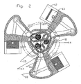
- the mechanism for the recovery of energy in self-propelled vehicles, object of the present invention is formed by, in the case of Figure 1 , a balanced rotary compressor with tangential pistons which is in turn formed by a block (11) with two cylinders (12) and a crank (14) with two pins (15).
- the assembly rotates when the brake, connected to the drive shaft by means of a clutch, is applied and the crank (14) remains fixed to the structure or support.
- the pistons (13) of the cylinders (12) that are diametrically opposite are actuated by pins (15) of the crank (14) that are equally shifted 180°.
- the elements having an inner shifting, such as pistons (13), connecting rods (18) and pivoted levers maintain at all times a 180° shift with their pair, achieving a homogeneous distribution of masses and balancing the assembly.
- the necessary elements completing the balanced rotary compressor, the cylinder head (120), the cover of the check valves, the air inlet and outlet ducts, are located in the upper part of the cylinder (12).
- the compressed air outlet (121) is sent to a suitable container through the front shaft of the compressor and a rotary joint (19).
- Figure 8 shows a variant of the compressor used in this first embodiment of the mechanism for the recovery of energy in self-propelled vehicles, where the crank (14) and the lower part (a) of the pivoted lever (16) are located in a sealed central chamber and the outer part (b) of this lever (16), with the connecting rod (18) and the piston (13) in another chamber, separated by the rotating shaft (17) of this pivoted lever (16).
- This arrangement facilitates the individual lubrication of each chamber, and allows the air to be drawn from the rear chamber of the cylinder (12), through a check valve (123) during the forward run of the piston (13), and injected during the return through the duct (124), to the compression chamber.
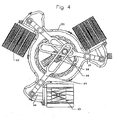
- the mechanism for the recovery of energy in self-propelled vehicles based on the compressor comprising an extendible crank ( Figures 4 , 5 , 6 and 7 ) basically consists of: block (21), cylinders (22), pistons (23), pivoted lever (26), connecting rods (28), and a crank (24) having a single pin (25), which moves, radially driven by pneumatic or hydraulic pressure.
- the block (21) rotates joined to the drive shaft of the vehicle, either by gears, belts or other means (222) and with it, all its elements (cylinders, pistons, connecting rods and pivoted lever) and the crank remains fixed to the structure of the vehicle.
- the crank (24) consist of a shaft (210) joined to a cylinder (211) and both of them have a hole (212) through which the driving agent flows to the base of the latter, a rod (213) joined to the pin (25) slides inside the cylinder.
- the position of the rod is determined by a control valve consisting of a piston (216) actuated by the brake and another piston (217) regulating the maximum pressure in the air storage system, a solenoid (218) is also provided which is activated in the event that a minimum pressure is needed in the system, which by means of a pressure switch actuates the system independently of the situation of the brake.
- crank (24) and the inner part of the pivoted arm (26) are located in a sealed central chamber and the outer part of said lever (26), with the connecting rod (28) and the piston (23) in another one, separated by the rotating shaft (27) of this pivoted lever (26).
- This arrangement facilitates the individual lubrication of each chamber, and allows the air to be drawn from the rear chamber of the cylinder (22), through a check valve during the forward run of the piston (23), and injected during the return through the duct (124) into the compression chamber.
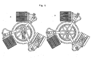
- Figure 7 shows the operation of the valve controlling the crank.
- pressure is sent to the piston (216) of the valve, which moves, allowing the hydraulic or pneumatic pressure of this system to pass to the cylinder (211) through the piston (217) regulating the air pressure of the storage system, moving the rod (214) to which the pin (25) of the crank (24) is joined up to the its run limit and causing the angular movement of the pivoted crank (26), which moves the pistons (23) linearly.
- FIG 7B when the brake is released and as there is no pressure in this system, the piston (216) recovers its position by means of its spring, the pressure of the system is cut off and the duct of the cylinder returned, thus the pressure exerted by the air on the pistons takes the crank to its rest position.
- the piston (218) which is actuated by a solenoid is provided in case a minimum air pressure is needed to be maintained in the system and can be activated by a pressure switch.
- Figure 7C shows the extendible crank (24) with a single pin (25) formed by a shaft coupled to the structure of the vehicle (210), a driving cylinder (211), a rod (213), grooves for limiting and orienting the crank (214) and limiting lugs (215).
Landscapes
- Engineering & Computer Science (AREA)
- Mechanical Engineering (AREA)
- General Engineering & Computer Science (AREA)
- Chemical & Material Sciences (AREA)
- Combustion & Propulsion (AREA)
- Transportation (AREA)
- Compressors, Vaccum Pumps And Other Relevant Systems (AREA)
- Transmission Devices (AREA)
- Arrangement Or Mounting Of Propulsion Units For Vehicles (AREA)
- Lasers (AREA)
- Vehicle Body Suspensions (AREA)
- Luminescent Compositions (AREA)
- Lubrication Of Internal Combustion Engines (AREA)
Claims (2)
- Mechanismus zur Rückgewinnung von Energie in selbstangetriebenen Fahrzeugen, der aus den folgenden Elementen gebildet wird:- einem ausbalancierten Rotationsverdichter mit tangentialen Kolben (13),- ein Block (13), der seinerseits durch zwei oder mehr Zylinder (12) gebildet wird, in denen jeweils ein Kolben (13) verschiebbar ist und durch einen Schwenkhebel (16) angetrieben wird,- wobei jeder Schwenkhebel (16) einen Innenarm (a) und einen Außenarm (b) hat, die um eine Welle (17) schwenken,- wobei jeder Innenarm (a) mit einer Nut versehen ist, in der ein exzentrischer Stift (15) einer Kurbel (14) verrutschbar angeordnet ist,- wobei jeder Außenarm (b) durch eine Verbindungsstange (18) mit dem jeweiligen Kolben (13) verbunden ist,- wobei der genannte Block (11) durch eine Kupplung mit einer Antriebswelle des Fahrzeugs verbunden ist, wobei die genannte Kupplung angetrieben wird, wenn eine Bremse angewendet wird, so dass der genannte Block mit all den Elementen rotiert, während die Kupplung (14) ortsfest an der Struktur befestigt bleibt,- so dass jeder exzentrische Stift (15) entlang der Nut des jeweiligen Innenarms (a) verrutscht, was ein Kippen des jeweiligen Schwenkhebels (16) auf seiner welle (17) verursacht, wobei diese winkelbewegung dann durch den jeweiligen Außenarm (b) und die Verbindungsstange (18) zu einer linearen Bewegung des jeweiligen Kolbens (13) übertragen wird,
dadurch gekennzeichnet, dass- die Kupplung (14) und die Innenarme (a) der Schwenkhebel (16) in einer abgedichteten zentralkammer gelegen sind und- jeder Außenarm (b) des Schwenkhebels (16), und die jeweilige Verbindungsstange (18) und Kolben (13) in einer anderen Kammer individuell durch die Welle (17) des Schwenkhebels (16) getrennt gelegen sind, wobei die individuelle Schmierung jeder genannten anderen Kammer gewährleistet wird,- wobei während des Vorwärtshubs des Kolbens (13) Luft von dem Hinterteil jedes Zylinders (12) durch ein Sperrventil (123) gesaugt wird, und während des Rückwärtshubs des Kolbens (13) Luft durch einen Kanal (124) in den Verdichtungsraum des Zylinders injiziert wird, wobei die genannte Verdiehtungskammer mit einem Lufteinlass verbunden wird,- wobei die Druckluft von der verdichtungskammer durch einen Lufteinlass (121) durch eine Welle des Verdichters und eine rotierende Dichtung (19) gesendet wird, so dass sie in einem geeigneten Behälter gespeichert wird. - Mechanismus zur Rückgewinnung von Energie in selbstangetriebenen Fahrzeugen nach Anspruch 1, dadurch gekennzeichnet, dass der Kolben jedes Zylinders durch mit der gleichen Gradzahl wie die Zylinder winkelig verschobene Stiften betrieben wird, wodurch eine gleichmäßige Verteilung aller Massen während der Rotation der Anordnung beibehalten wird, und der Block mit der Antriebswelle des Fahrzeugs durch die Kupplung verbunden ist, wenn die Bremse angewendet wird.
Applications Claiming Priority (3)
| Application Number | Priority Date | Filing Date | Title |
|---|---|---|---|
| ES200401020A ES2263331B1 (es) | 2004-04-29 | 2004-04-29 | Mecanismo para la recuperacion de energia en forma de presion neumatica en vehiculos autopropulsados. |
| ES200401927 | 2004-08-03 | ||
| PCT/ES2005/070048 WO2005105503A1 (es) | 2004-04-29 | 2005-04-21 | Mecanismo recuperador de energía en vehículos autopropulsados |
Publications (2)
| Publication Number | Publication Date |
|---|---|
| EP1749685A1 EP1749685A1 (de) | 2007-02-07 |
| EP1749685B1 true EP1749685B1 (de) | 2008-11-26 |
Family
ID=35241530
Family Applications (1)
| Application Number | Title | Priority Date | Filing Date |
|---|---|---|---|
| EP05735160A Expired - Lifetime EP1749685B1 (de) | 2004-04-29 | 2005-04-21 | Mechanismus zur energierückgewinnung bei selbstfahrenden fahrzeugen |
Country Status (8)
| Country | Link |
|---|---|
| US (1) | US20090155107A1 (de) |
| EP (1) | EP1749685B1 (de) |
| JP (1) | JP2007534552A (de) |
| AT (1) | ATE415306T1 (de) |
| AU (1) | AU2005237798A1 (de) |
| CA (1) | CA2564329A1 (de) |
| DE (1) | DE602005011275D1 (de) |
| WO (1) | WO2005105503A1 (de) |
Families Citing this family (9)
| Publication number | Priority date | Publication date | Assignee | Title |
|---|---|---|---|---|
| US9353736B1 (en) * | 2005-11-21 | 2016-05-31 | Saverio Scalzi | Modular radial compressor |
| DE102007011257A1 (de) * | 2007-03-08 | 2008-09-11 | Knorr-Bremse Systeme für Nutzfahrzeuge GmbH | Hybridantrieb, Verfahren zum Steuern eines Druckluftkompressors und Kraftfahrzeug mit einem Hybridantrieb |
| US7762066B2 (en) * | 2008-01-24 | 2010-07-27 | Tonand Brakes, Inc. | Regeneration system |
| US8225900B2 (en) | 2008-04-26 | 2012-07-24 | Domes Timothy J | Pneumatic mechanical power source |
| US8561747B2 (en) | 2008-04-26 | 2013-10-22 | Timothy Domes | Pneumatic mechanical power source |
| US9175564B2 (en) | 2011-12-05 | 2015-11-03 | Parker-Hannifin Corporation | Tank sloshing energy recovery system |
| ES2429414A1 (es) * | 2012-04-10 | 2013-11-14 | Francisco Javier RUIZ MARTÍNEZ | Bomba o Compresor Rotativo |
| DE102015006988A1 (de) | 2015-05-29 | 2016-12-01 | Man Truck & Bus Ag | Verfahren und Regelkreis zur Regelung eines elektrischen Antriebs eines elektrisch angetriebenen Druckluftverdichters eines Kraftfahrzeugs |
| ES2646987B1 (es) * | 2016-06-17 | 2018-08-10 | Francisco Javier Ruiz Martinez | Mecanismo rotativo impulsado por motores eléctricos lineales |
Family Cites Families (9)
| Publication number | Priority date | Publication date | Assignee | Title |
|---|---|---|---|---|
| FR1376714A (fr) * | 1963-09-17 | 1964-10-31 | Hispano Suiza Sa | Perfectionnements apportés aux compresseurs volumétriques alternatifs hermétiques, notamment à ceux à pistons |
| US4106391A (en) * | 1977-01-31 | 1978-08-15 | Wheeler Roland T | Motor |
| JPS56108312A (en) * | 1979-11-15 | 1981-08-27 | Akira Kato | Device for storing kinetic energy at deceleration and stoppage of moving vehicle and for starting it |
| ES8502923A1 (es) * | 1984-02-23 | 1985-02-01 | Ruiz Guinea Jose M | Instalacion para el frenado y aprovechamiento de la energia cinetica de un vehiculo. |
| US5182977A (en) * | 1991-09-12 | 1993-02-02 | William Gulbrantson | Hydraulic centrifugal piston motor |
| ES2065801B1 (es) * | 1992-02-07 | 1997-04-16 | Martinez Fco Javier Ruiz | Bomba o compresor de embolos tangenciales. |
| US5638738A (en) * | 1996-01-24 | 1997-06-17 | Ingersoll-Rand Company | Air motor piston to crank linkage |
| JP3789691B2 (ja) * | 1999-09-14 | 2006-06-28 | 三洋電機株式会社 | 高圧圧縮機の圧縮装置 |
| MXPA02005711A (es) * | 1999-12-07 | 2004-09-10 | Harcourt Engine Pty Ltd | Motor. |
-
2005
- 2005-04-21 CA CA002564329A patent/CA2564329A1/en not_active Abandoned
- 2005-04-21 AU AU2005237798A patent/AU2005237798A1/en not_active Abandoned
- 2005-04-21 JP JP2007510057A patent/JP2007534552A/ja active Pending
- 2005-04-21 US US11/568,453 patent/US20090155107A1/en not_active Abandoned
- 2005-04-21 DE DE602005011275T patent/DE602005011275D1/de not_active Expired - Lifetime
- 2005-04-21 AT AT05735160T patent/ATE415306T1/de not_active IP Right Cessation
- 2005-04-21 WO PCT/ES2005/070048 patent/WO2005105503A1/es not_active Ceased
- 2005-04-21 EP EP05735160A patent/EP1749685B1/de not_active Expired - Lifetime
Also Published As
| Publication number | Publication date |
|---|---|
| AU2005237798A1 (en) | 2005-11-10 |
| DE602005011275D1 (de) | 2009-01-08 |
| EP1749685A1 (de) | 2007-02-07 |
| WO2005105503A1 (es) | 2005-11-10 |
| CA2564329A1 (en) | 2005-11-10 |
| ATE415306T1 (de) | 2008-12-15 |
| JP2007534552A (ja) | 2007-11-29 |
| US20090155107A1 (en) | 2009-06-18 |
Similar Documents
| Publication | Publication Date | Title |
|---|---|---|
| US5465817A (en) | Hydraulic brake pump with eccentric cam and reciprocating piston | |
| KR20020068067A (ko) | 유압 하이브리드 자동차 | |
| EP1749685A1 (de) | Mechanismus zur energierückgewinnung bei selbstfahrenden fahrzeugen | |
| JP6976331B2 (ja) | ロストモーションロッカーアームアセンブリの圧縮解放エンジンブレーキシステムおよびその動作方法 | |
| JPH06200713A (ja) | 内燃機関用弁機構装置 | |
| US5373921A (en) | Hydraulic gearwheel brake pump | |
| CN100515814C (zh) | 机动车辆中的能量回收装置 | |
| EP1748152A1 (de) | Gleichgewichtsrotationsmotor | |
| KR970059532A (ko) | 작업차량의 트랜스미션 | |
| US4148249A (en) | Axially balanced, adjustable volume rotary machine and drive system utilizing same | |
| US602618A (en) | eyster | |
| JP2715558B2 (ja) | 斜板型可変容量圧縮機 | |
| KR100224259B1 (ko) | 에어컴퓨레서 | |
| US20050198953A1 (en) | Hydrostatic continuously variable transmission | |
| US1212302A (en) | Power-brake. | |
| US20110132300A1 (en) | Driving assembly for a motor vehicle engine brake | |
| KR100943016B1 (ko) | 이중 유압 머신 트랜스미션 | |
| US1806652A (en) | Automatic accelerator | |
| US2704923A (en) | Rotary pump and motor hydraulic transmission | |
| JP3505252B2 (ja) | 容量可変斜板式コンプレッサ | |
| US1256501A (en) | Hydraulic variable-speed transmission. | |
| US402525A (en) | Samuel c | |
| JP2730722B2 (ja) | 静油圧式無段変速機 | |
| JP2006316626A (ja) | 自動車のエネルギー回生装置 | |
| EP1446555A1 (de) | Verfahren und vorrichtung für ein kraftfahrzeug-energieerzeugungssystem |
Legal Events
| Date | Code | Title | Description |
|---|---|---|---|
| PUAI | Public reference made under article 153(3) epc to a published international application that has entered the european phase |
Free format text: ORIGINAL CODE: 0009012 |
|
| 17P | Request for examination filed |
Effective date: 20061121 |
|
| AK | Designated contracting states |
Kind code of ref document: A1 Designated state(s): AT BE BG CH CY CZ DE DK EE ES FI FR GB GR HU IE IS IT LI LT LU MC NL PL PT RO SE SI SK TR |
|
| DAX | Request for extension of the european patent (deleted) | ||
| 17Q | First examination report despatched |
Effective date: 20071123 |
|
| GRAP | Despatch of communication of intention to grant a patent |
Free format text: ORIGINAL CODE: EPIDOSNIGR1 |
|
| GRAS | Grant fee paid |
Free format text: ORIGINAL CODE: EPIDOSNIGR3 |
|
| GRAA | (expected) grant |
Free format text: ORIGINAL CODE: 0009210 |
|
| AK | Designated contracting states |
Kind code of ref document: B1 Designated state(s): AT BE BG CH CY CZ DE DK EE ES FI FR GB GR HU IE IS IT LI LT LU MC NL PL PT RO SE SI SK TR |
|
| REG | Reference to a national code |
Ref country code: GB Ref legal event code: FG4D |
|
| REG | Reference to a national code |
Ref country code: CH Ref legal event code: EP |
|
| REG | Reference to a national code |
Ref country code: IE Ref legal event code: FG4D |
|
| REF | Corresponds to: |
Ref document number: 602005011275 Country of ref document: DE Date of ref document: 20090108 Kind code of ref document: P |
|
| PG25 | Lapsed in a contracting state [announced via postgrant information from national office to epo] |
Ref country code: LT Free format text: LAPSE BECAUSE OF FAILURE TO SUBMIT A TRANSLATION OF THE DESCRIPTION OR TO PAY THE FEE WITHIN THE PRESCRIBED TIME-LIMIT Effective date: 20081126 Ref country code: ES Free format text: LAPSE BECAUSE OF FAILURE TO SUBMIT A TRANSLATION OF THE DESCRIPTION OR TO PAY THE FEE WITHIN THE PRESCRIBED TIME-LIMIT Effective date: 20090308 Ref country code: AT Free format text: LAPSE BECAUSE OF FAILURE TO SUBMIT A TRANSLATION OF THE DESCRIPTION OR TO PAY THE FEE WITHIN THE PRESCRIBED TIME-LIMIT Effective date: 20081126 |
|
| NLV1 | Nl: lapsed or annulled due to failure to fulfill the requirements of art. 29p and 29m of the patents act | ||
| PG25 | Lapsed in a contracting state [announced via postgrant information from national office to epo] |
Ref country code: IS Free format text: LAPSE BECAUSE OF FAILURE TO SUBMIT A TRANSLATION OF THE DESCRIPTION OR TO PAY THE FEE WITHIN THE PRESCRIBED TIME-LIMIT Effective date: 20090326 Ref country code: PL Free format text: LAPSE BECAUSE OF FAILURE TO SUBMIT A TRANSLATION OF THE DESCRIPTION OR TO PAY THE FEE WITHIN THE PRESCRIBED TIME-LIMIT Effective date: 20081126 Ref country code: NL Free format text: LAPSE BECAUSE OF FAILURE TO SUBMIT A TRANSLATION OF THE DESCRIPTION OR TO PAY THE FEE WITHIN THE PRESCRIBED TIME-LIMIT Effective date: 20081126 Ref country code: SI Free format text: LAPSE BECAUSE OF FAILURE TO SUBMIT A TRANSLATION OF THE DESCRIPTION OR TO PAY THE FEE WITHIN THE PRESCRIBED TIME-LIMIT Effective date: 20081126 Ref country code: FI Free format text: LAPSE BECAUSE OF FAILURE TO SUBMIT A TRANSLATION OF THE DESCRIPTION OR TO PAY THE FEE WITHIN THE PRESCRIBED TIME-LIMIT Effective date: 20081126 |
|
| PG25 | Lapsed in a contracting state [announced via postgrant information from national office to epo] |
Ref country code: RO Free format text: LAPSE BECAUSE OF FAILURE TO SUBMIT A TRANSLATION OF THE DESCRIPTION OR TO PAY THE FEE WITHIN THE PRESCRIBED TIME-LIMIT Effective date: 20081126 Ref country code: BG Free format text: LAPSE BECAUSE OF FAILURE TO SUBMIT A TRANSLATION OF THE DESCRIPTION OR TO PAY THE FEE WITHIN THE PRESCRIBED TIME-LIMIT Effective date: 20090226 Ref country code: EE Free format text: LAPSE BECAUSE OF FAILURE TO SUBMIT A TRANSLATION OF THE DESCRIPTION OR TO PAY THE FEE WITHIN THE PRESCRIBED TIME-LIMIT Effective date: 20081126 Ref country code: DK Free format text: LAPSE BECAUSE OF FAILURE TO SUBMIT A TRANSLATION OF THE DESCRIPTION OR TO PAY THE FEE WITHIN THE PRESCRIBED TIME-LIMIT Effective date: 20081126 Ref country code: BE Free format text: LAPSE BECAUSE OF FAILURE TO SUBMIT A TRANSLATION OF THE DESCRIPTION OR TO PAY THE FEE WITHIN THE PRESCRIBED TIME-LIMIT Effective date: 20081126 |
|
| PG25 | Lapsed in a contracting state [announced via postgrant information from national office to epo] |
Ref country code: CZ Free format text: LAPSE BECAUSE OF FAILURE TO SUBMIT A TRANSLATION OF THE DESCRIPTION OR TO PAY THE FEE WITHIN THE PRESCRIBED TIME-LIMIT Effective date: 20081126 Ref country code: SE Free format text: LAPSE BECAUSE OF FAILURE TO SUBMIT A TRANSLATION OF THE DESCRIPTION OR TO PAY THE FEE WITHIN THE PRESCRIBED TIME-LIMIT Effective date: 20090226 Ref country code: PT Free format text: LAPSE BECAUSE OF FAILURE TO SUBMIT A TRANSLATION OF THE DESCRIPTION OR TO PAY THE FEE WITHIN THE PRESCRIBED TIME-LIMIT Effective date: 20090427 |
|
| PG25 | Lapsed in a contracting state [announced via postgrant information from national office to epo] |
Ref country code: SK Free format text: LAPSE BECAUSE OF FAILURE TO SUBMIT A TRANSLATION OF THE DESCRIPTION OR TO PAY THE FEE WITHIN THE PRESCRIBED TIME-LIMIT Effective date: 20081126 |
|
| PLBE | No opposition filed within time limit |
Free format text: ORIGINAL CODE: 0009261 |
|
| STAA | Information on the status of an ep patent application or granted ep patent |
Free format text: STATUS: NO OPPOSITION FILED WITHIN TIME LIMIT |
|
| 26N | No opposition filed |
Effective date: 20090827 |
|
| REG | Reference to a national code |
Ref country code: CH Ref legal event code: PL |
|
| PG25 | Lapsed in a contracting state [announced via postgrant information from national office to epo] |
Ref country code: CH Free format text: LAPSE BECAUSE OF NON-PAYMENT OF DUE FEES Effective date: 20090430 Ref country code: LI Free format text: LAPSE BECAUSE OF NON-PAYMENT OF DUE FEES Effective date: 20090430 |
|
| REG | Reference to a national code |
Ref country code: IE Ref legal event code: MM4A |
|
| PG25 | Lapsed in a contracting state [announced via postgrant information from national office to epo] |
Ref country code: MC Free format text: LAPSE BECAUSE OF NON-PAYMENT OF DUE FEES Effective date: 20090430 Ref country code: IE Free format text: LAPSE BECAUSE OF NON-PAYMENT OF DUE FEES Effective date: 20090421 |
|
| PG25 | Lapsed in a contracting state [announced via postgrant information from national office to epo] |
Ref country code: GR Free format text: LAPSE BECAUSE OF FAILURE TO SUBMIT A TRANSLATION OF THE DESCRIPTION OR TO PAY THE FEE WITHIN THE PRESCRIBED TIME-LIMIT Effective date: 20090227 |
|
| PG25 | Lapsed in a contracting state [announced via postgrant information from national office to epo] |
Ref country code: LU Free format text: LAPSE BECAUSE OF NON-PAYMENT OF DUE FEES Effective date: 20090421 |
|
| PG25 | Lapsed in a contracting state [announced via postgrant information from national office to epo] |
Ref country code: HU Free format text: LAPSE BECAUSE OF FAILURE TO SUBMIT A TRANSLATION OF THE DESCRIPTION OR TO PAY THE FEE WITHIN THE PRESCRIBED TIME-LIMIT Effective date: 20090527 |
|
| PGFP | Annual fee paid to national office [announced via postgrant information from national office to epo] |
Ref country code: DE Payment date: 20110421 Year of fee payment: 7 Ref country code: FR Payment date: 20110510 Year of fee payment: 7 |
|
| PG25 | Lapsed in a contracting state [announced via postgrant information from national office to epo] |
Ref country code: TR Free format text: LAPSE BECAUSE OF FAILURE TO SUBMIT A TRANSLATION OF THE DESCRIPTION OR TO PAY THE FEE WITHIN THE PRESCRIBED TIME-LIMIT Effective date: 20081126 |
|
| PGFP | Annual fee paid to national office [announced via postgrant information from national office to epo] |
Ref country code: GB Payment date: 20110421 Year of fee payment: 7 |
|
| PG25 | Lapsed in a contracting state [announced via postgrant information from national office to epo] |
Ref country code: CY Free format text: LAPSE BECAUSE OF FAILURE TO SUBMIT A TRANSLATION OF THE DESCRIPTION OR TO PAY THE FEE WITHIN THE PRESCRIBED TIME-LIMIT Effective date: 20081126 |
|
| PGFP | Annual fee paid to national office [announced via postgrant information from national office to epo] |
Ref country code: IT Payment date: 20110420 Year of fee payment: 7 |
|
| GBPC | Gb: european patent ceased through non-payment of renewal fee |
Effective date: 20120421 |
|
| REG | Reference to a national code |
Ref country code: FR Ref legal event code: ST Effective date: 20121228 |
|
| PG25 | Lapsed in a contracting state [announced via postgrant information from national office to epo] |
Ref country code: GB Free format text: LAPSE BECAUSE OF NON-PAYMENT OF DUE FEES Effective date: 20120421 |
|
| REG | Reference to a national code |
Ref country code: DE Ref legal event code: R119 Ref document number: 602005011275 Country of ref document: DE Effective date: 20121101 |
|
| PG25 | Lapsed in a contracting state [announced via postgrant information from national office to epo] |
Ref country code: FR Free format text: LAPSE BECAUSE OF NON-PAYMENT OF DUE FEES Effective date: 20120430 Ref country code: IT Free format text: LAPSE BECAUSE OF NON-PAYMENT OF DUE FEES Effective date: 20120421 |
|
| PG25 | Lapsed in a contracting state [announced via postgrant information from national office to epo] |
Ref country code: DE Free format text: LAPSE BECAUSE OF NON-PAYMENT OF DUE FEES Effective date: 20121101 |