EP1749331B1 - Mobile radio antenna with beam-forming element - Google Patents
Mobile radio antenna with beam-forming element Download PDFInfo
- Publication number
- EP1749331B1 EP1749331B1 EP05745719A EP05745719A EP1749331B1 EP 1749331 B1 EP1749331 B1 EP 1749331B1 EP 05745719 A EP05745719 A EP 05745719A EP 05745719 A EP05745719 A EP 05745719A EP 1749331 B1 EP1749331 B1 EP 1749331B1
- Authority
- EP
- European Patent Office
- Prior art keywords
- plane
- reflector
- operating
- antenna
- section
- Prior art date
- Legal status (The legal status is an assumption and is not a legal conclusion. Google has not performed a legal analysis and makes no representation as to the accuracy of the status listed.)
- Not-in-force
Links
Images

Classifications
-
- H—ELECTRICITY
- H01—ELECTRIC ELEMENTS
- H01Q—ANTENNAS, i.e. RADIO AERIALS
- H01Q1/00—Details of, or arrangements associated with, antennas
- H01Q1/12—Supports; Mounting means
- H01Q1/22—Supports; Mounting means by structural association with other equipment or articles
- H01Q1/24—Supports; Mounting means by structural association with other equipment or articles with receiving set
- H01Q1/241—Supports; Mounting means by structural association with other equipment or articles with receiving set used in mobile communications, e.g. GSM
- H01Q1/246—Supports; Mounting means by structural association with other equipment or articles with receiving set used in mobile communications, e.g. GSM specially adapted for base stations
-
- H—ELECTRICITY
- H01—ELECTRIC ELEMENTS
- H01Q—ANTENNAS, i.e. RADIO AERIALS
- H01Q21/00—Antenna arrays or systems
- H01Q21/24—Combinations of antenna units polarised in different directions for transmitting or receiving circularly and elliptically polarised waves or waves linearly polarised in any direction
-
- H—ELECTRICITY
- H01—ELECTRIC ELEMENTS
- H01Q—ANTENNAS, i.e. RADIO AERIALS
- H01Q5/00—Arrangements for simultaneous operation of antennas on two or more different wavebands, e.g. dual-band or multi-band arrangements
- H01Q5/40—Imbricated or interleaved structures; Combined or electromagnetically coupled arrangements, e.g. comprising two or more non-connected fed radiating elements
- H01Q5/42—Imbricated or interleaved structures; Combined or electromagnetically coupled arrangements, e.g. comprising two or more non-connected fed radiating elements using two or more imbricated arrays
Definitions
- Antennas in particular in the form of stationary mobile radio antennas are well known.
- an antenna array with a plurality of vertically stacked primary radiator modules which radiate and receive in a position, for example, with vertical orientation.
- the individual radiating element can consist of dipole radiators or dipole radiator arrangements.
- antennas in particular in the form of antenna arrays, which can transmit and / or receive in two mutually orthogonal polarization planes are also known.
- dual polarized antennas are for example from DE 198 60 121 A1 known.
- the two mutually perpendicular polarization planes are rotated at a 45 ° angle relative to the horizontal (or vertical). This is also common spoken of a so-called X-polarization or orientation of the radiator elements.
- dipole radiators are again preferably used, for example, cross-shaped dipole radiators or dipole squares.
- vector dipoles come into consideration, as they basically from the DE 198 60 121 A1 are known.
- These dipole structures are a dual-polarized radiator arrangement which is constructed in the electrical manner in the manner of a crossed dipole and is more closely approximated in terms of construction to a quadratic structure.
- Beam-shaping elements for influencing the radiation pattern are basically, for example, from US 5,629,713 A known. It is a horizontally polarized antenna which symmetrically to the central longitudinal axis on each left and right on a horizontally oriented dipole radiator so-called parasitic radiator shows, which are also designed dipolstrahlerä Inc, namely with a central support column, of the parasitic in a horizontal plane to the left and right Stand aside dipole halves. These dipole halves or dipole arms extend from their middle fastening and holding point obliquely downwards in the direction of the reflector plane, in such a way that an angle of 90 ° is formed between the two reflector halves.
- pure decoupling elements are also known in the prior art which are not beamforming, in particular taking into account a far-field diagram, but merely decoupling between serve two perpendicular polarizations.
- decoupling elements for decoupling between two polarizations in the case of a dual-polarized antenna are known, for example, from US Pat WO 01/04991 A1 or the WO 98/01923 A1 known.
- a generic radiator arrangement for the use of patch antennas is for example also from WO 98/36472 A1 to be known as known. Described is an antenna with horizontally and vertically aligned patch elements, which in each case in the horizontal direction outside relative to the reflector plane in the radiator direction elevating path sections are assigned. In one embodiment, these web portions may also be provided with opposite outwardly extending wing members having a length in the vertical direction, corresponding to the length of the webs carrying them and rising from the reflector. In a further embodiment dual polarized patch radiators are shown, which are aligned in the polarization plane at a + 45 ° or -45 ° angle to the horizontal or vertical.
- an object of the present invention to provide an improved antenna, in particular in the form of a dual-polarized, stationary antenna for a base station for the mobile radio area, which is equipped with a device for performing a beam shaping.
- an improved antenna in particular in the form of a dual-polarized, stationary antenna for a base station for the mobile radio area, which is equipped with a device for performing a beam shaping.
- it should be possible according to the invention to be able to make an improved shaping of far-field diagrams for such antennas.
- the invention can be used in a radiator arrangement which radiates in two polarization planes.
- the invention has advantages especially in a dual polarized antenna.
- the invention is not limited to a single-band antenna, but can also be implemented and implemented in a dual-band or generally a multi-band antenna.
- the present invention is also characterized by the fact that the desired improvement explained by comparatively simple and inexpensive measures can be realized. Furthermore, the measures that effect the improvement can be used selectively and, above all, assigned to individual radiators or radiator elements.
- the measures according to the invention can be used and used not only in dual-polarized antennas with dipole radiators but, for example, also in patch antennas. In principle, there are no restrictions on certain emitter shapes.
- the solution according to the invention is characterized inter alia by the fact that at least four passive electrically conductive Elements are provided which are at least indirectly galvanically connected to the electrically conductive reflector or capacitively coupled.
- the inventively provided at least four passive electrically conductive elements which are additionally provided for at least one radiator or a radiator arrangement, are divided into at least two parts and each comprise a support portion, which preferably emanates from the reflector and electrically connected thereto or capacitively coupled and preferably at least indirectly mechanically connected to the reflector.
- a so-called active portion is then provided, which is preferably arranged in a direction parallel to the reflector plane.
- this effective portion may be arranged at least in an angular range of less than ⁇ 20 °, preferably less than ⁇ 10 ° deviating from the orientation of the reflector plane, ie extend at an angle to the reflector plane.
- this effective section has a length of preferably 0.2 ⁇ to 1.0 inclusive ⁇ , where ⁇ corresponds to the wavelength in the frequency range or frequency band to be transmitted, preferably the average wavelength of the frequency range to be transmitted.
- the active plane itself can be arranged above or below the radiator plane of the active radiator to be influenced. A restriction is not specified here. However, the length of the support portion which is greater than the distance of the active portion of the passive electrically conductive element to the reflector, do not exceed a maximum value corresponding to twice the aforementioned wavelength.
- the at least four beam-shaping elements are designed in such a way that the at least two pairs of support sections run apart from the plane of the reflector in the plane of action and the effective sections adjoining the upper end of the support section converge again.
- the material thickness or the transverse dimensions should be transverse to the direction of extension of the electrically conductive additionally provided Strahlformerides less than 0.1 of the operating wavelength, preferably the average operating wavelength of the element to be influenced.
- This may be a rod-shaped or cross-shaped decoupling structure, which is arranged between two dual-polarized radiators, in order to improve or to effect a decoupling between the two polarizations in the case of a dual-polarized antenna.
- the aim of the present invention is not to ensure a decoupling element for improving the decoupling between two dual-polarized radiation planes. Rather, the aim of the present invention is to modify and shape the radiation pattern as desired, especially in far-field viewing. Therefore, it is also provided according to the invention that the active portion of the electrically conductive beam-forming element according to the invention extends at least substantially or approximately in the above-mentioned preferably parallel to the reflector plane extending working plane in the polarization direction of the element to be influenced. Again, deviations of preferably less than 20%, in particular less than 10%, can also bring about the desired inventive success.
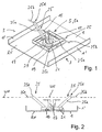
- the antenna according to FIGS. 1 and 2 comprises a reflector arrangement or a reflector 1, which is conductive.
- a radiator arrangement 5 is preferably provided in the middle region, which in the example shown consists of a single radiator 5a.
- the single radiator 5a is in this example formed from a simple polarized dipole radiator which radiates in a plane perpendicular to the plane of the reflector 1 (ie, sends and / or receives).
- the reflector 1 is designed substantially flat at least in the area of the radiator arrangement 5.
- reflector webs or wall sections 1 'projecting transversely to the reflector plane and extending in the beam direction are provided on the longitudinal side regions 3. These need not necessarily be arranged on the outer lateral end of the reflector 1, but may also be provided lying further inside.
- additional webs or outer side boundary sections may be arranged, as for example from the Vorveröttingungen WO 99/62138 A1 of the US 5,710,569 A or the EP 0 916 169 B1 is known.
- the illustrated antenna arrangement is usually set up so that the reflector 1 extends lying in a vertical plane, while the mentioned in the side region arranged webs 1 'also extend in the vertical direction.
- the linearly polarized radiator or the linearly polarized radiator arrangement could also be oriented differently, for example in such a way that the plane of polarization does not lie in a horizontal plane but deviates from it in another plane, for example in the vertical direction.
- the radiator arrangement would then be aligned rotated by 90 ° with the Abstrahlformungselement still to be explained below, so that the dipole radiator then parallel to the laterally provided webs 1 'extends.
- the radiator 5 is constructed essentially in a known manner and comprises two dipole halves 15, which is held in the form of a balancing 17 via a dipole support device.
- the radiator arrangement is arranged in a field 19 on the reflector 1, which is designed at least approximately square in plan view and has a circumferential ridge or a circumferential wall 21.
- a passive electrically conductive element 25 is now provided, which is also referred to below as a beam-shaping element 25.
- this beam-shaping element 25 is at least approximately divided into two sections, namely a support section 25a and a so-called active section 25b.
- the support portion 25a which is like the active portion 25b electrically conductive or provided with an electrically conductive surface or partially with an electrically conductive surface, also contributes to the overall effect, the effect is therefore not triggered alone on the so-called active portion 25b ,
- the support section 25a is preferably arranged directly electrically galvanically on the reflector 1 and connected to this electrically and preferably mechanically.
- the connection can also be capacitive, so that the support portion 25a and in particular its base 25c is capacitively coupled to the reflector 1.
- the mechanical and / or electrical-galvanic or electrically capacitive connection or coupling can but with the reflector 1 also indirectly take place by a corresponding connection via additional intermediate element or with the base of the balancing 17 is made.
- a conductive ring structure 29 is provided on the reflector 1 and at the base of the symmetrization 17 on which the foot portion of the support portion 25a is mechanically and electrically connected (or in the case of capacitive coupling capacitively coupled here with the interposition of an insulator or dielectric is).
- the so-called active section 25b adjoins the upper end of the support section 25a at a so-called transition region or transition point 25d, which preferably lies in a working plane WE.
- This active plane WE is preferably aligned parallel to the plane of the reflector 1, i. are arranged at least parallel to that reflector portion in the region of the radiator or the radiator-forming element.
- the active section 25b or its essential or predominant parts need not necessarily be aligned exactly parallel to the respective reflector section or reflector 1. Deviations from the relevant section of the reflector of preferably less than ⁇ 20 °, in particular less than ⁇ 10 ° still lead to the desired effects.
- the length of the support section from the lower foot 25c to the level of the active plane ie in particular to the transition region 25d longer than the distance between the reflector plane RE and the active plane WE.
- the support portion 25a should be greater than the distance of the active plane WE to the reflector plane RE at least in the area
- the length of the carrier should preferably not exceed twice the wavelength (2 ⁇ ) of the associated operating center wavelength of the emitter array 5, this wavelength being at the lower or upper end of the frequency band to be considered, preferably corresponding to the wavelength lying in the middle frequency band.
- the length of the effective section 25b in the direction of the active plane WE should preferably correspond to 0.2 ⁇ to and including ⁇ 1.0 ⁇ , based on the operating wavelength (in particular the mean operating wavelength of a frequency band to be transmitted).
- the plane of action itself may be both below, above and at the level of the active radiating element, i. the dipole halves 15 are.
- the active plane (in particular in the region of the effective section 25b) should be at a distance of preferably 0.2 ⁇ to 1.5 ⁇ inclusive, where ⁇ again corresponds to the wavelength of the frequency band to be transmitted, preferably the central wavelength of the frequency band to be transmitted.
- the active section 25b is arranged co-polar, that is to say it is aligned in the direction of the plane of polarization.
- the polarization plane PE remains perpendicular to the reflector 1, with the dipole halves 15 lying in this plane of polarization PE and .alpha there in the preferred embodiment ultimately also the support portion 25a and the effective portion 25b of the beam-shaping elements 25 come to rest.
- two beam-shaping elements 25 are provided for the only dipole radiator provided, which extend symmetrically to a plane perpendicular to the reflector 1 and perpendicular to the polarization plane PE and through the center of the radiator arrangement 5.
- radiator assembly 5 which in this embodiment, however, consists of two individual dipole radiators 5a and 5b, which are designed in the manner of a dipole cross.
- the two dipole radiators oriented perpendicular to one another are preferably arranged rotated at an angle of + 45 ° with respect to the horizontal or vertical plane, so that this radiator arrangement comprises two polarization planes PE that are perpendicular to each other in + 45 ° and -45 °.
- one beam-shaping element 25 is now provided for each dipole half, i. two beam shaping elements according to the invention for each polarization plane PE.
- the associated support sections 25a are preferably each again in one of the respective polarization planes of the associated dipole arrangement.
- the at the top At the end of the respective support section 25a subsequent active section 25b is aligned to the plane of polarization, in which the associated support section 25a is arranged to extend in a plane perpendicular to polarization, ie aligned parallel to the other polarization plane.
- the length and size ratios are comparable to the embodiment of Figure 1 and 2.
- the arrangement may also be such that the support portion 25a is not necessarily in each associated polarization plane PE, but between its base and its transition region to the associated active portion 25b and from this Level out or is arranged at an angle at right angles to the polarization plane. Deviations of less than ⁇ 20 °, in particular less than ⁇ 10 ° are possible.
- the effective portions 25b each extend parallel to an associated polarization plane PE (with lateral distance to the polarization plane of the associated radiator), whereby deviations of less than ⁇ 20 °, in particular less than ⁇ 10 ° with respect to the polarization plane are possible , Deviations of the active plane WE or the orientation of the active sections 25b in relation to the same may also occur in the same area Move reflector plane, so this deviation is less than ⁇ 20 °, in particular ⁇ 10 °, should be.
- FIG. 4 differs from that according to FIG. 3 in that a square compact radiator is used as the cross-shaped polarized radiator arrangement 5.
- This is a radiator arrangement, as in principle from the DE 198 60 121 A1 is known.
- the outer corners of the conductive structure can be open (as in the DE 198 60 121 A1 has been described) or by means of an insulator or dielectric or electrically closed. Reference is here made to known solutions. Also in this case the polarization planes are oriented at an angle of + 45 ° and -45 °, respectively, with respect to a horizontal or vertical.
- the electrically cross-shaped dipole radiator structure according to FIG. 4 is a radiator arrangement, which is sometimes referred to as a vector radiator or a cross-vector radiator or radiator arrangement.
- a dual-band antenna array in particular for a stationary mobile radio antenna, may comprise a conventional radiator arrangement with radiators 115 for a higher frequency band and radiator arrangements 215 for transmission in a lower frequency band.
- the radiator arrangement 215 for transmission in the lower frequency band consists in each case of two pairs of dipoles 215 'and 215 "arranged parallel to one another and arranged in such a way that a dipole square is formed Emitter provided in the higher frequency band whose dipole radiator elements lie on a plane closer to the reflector plane RE than the dipole elements 215 'and 215 "of the radiator elements radiating in the higher frequency band
- the radiator arrangement 215 is provided for transmission and / or reception in the lower frequency band (this may preferably be a frequency band, which is operated, for example, at half the frequency with respect to the frequency in the higher frequency band, but a limitation on this is not absolutely necessary.)
- Both the internal radiators 115 and the external radiators 215 are so arranged and aligned so that both radiator types radiate in two mutually perpendicular planes of polarization, which are aligned in the embodiment shown at an angle of + 45 ° and -45 ° relative to a horizontal or vertical plane.
- an additional radiator arrangement 115 is then arranged between the centers of the two radiator arrangements 215 on the reflector 1 (in particular when transmitting in a frequency band twice as high as the low frequency band, the beam sequence and thus the radiator spacing are between the radiators for the higher frequency band only half as large as for the lower frequency band). If, for the central emitter array 115, that is to say for the emitter array 115 respectively situated between two emitter array 215 provided for the low frequency range, those beam shaping elements 25 are used, as described in the exemplary embodiment according to FIG. 4, a structure results according to the example according to FIG. 5.
- the beam-shaping elements 25 are shaped with the respective support section 25a and the adjoining effective section 25b in this exemplary embodiment in such a way that the respective support section 25a has a part of the support or the symmetrization 17 corresponding dipole arrangement for radiating in the lower frequency band radiator assembly 115 and then the support portion 25a subsequent effective portion 25b of a respective associated dipole half 215 'of an adjacent radiator assembly 215, that is preferably aligned parallel thereto.
- the support portion 25'a substantially in the same length, the same orientation and slope parallel to the one part of the support portion or the symmetrization 17 'and the further support portion 25 "a in corresponding, in plan view offset by 90 ° orientation and otherwise the same pitch and similar or comparable length as the associated part of the support section or the symmetrization 17 "of the radiator 215 arranged and positioned, ie also at the same distance from the vertical side edge 1 'of the reflector 1 or in the same side distance from one of the middle perpendicular to the reflector plane extending vertical plane etc.
- the effective portions 25b are arranged in a plane of action WE parallel to the reflector, in which also come the dipole elements 215 'provided for the lower frequency band dipole radiator 215 to lie.
- the length of the effective portions 25b corresponds approximately to the length of the respective dipole half for the lower frequency band or deviates by less than 40%, in particular less than 30%, less than 20% or even less than 10% thereof.
- the arrangement of the effective sections in Relation to the reflector comparable to the arrangement of the dipole halves of the adjacent radiators for transmission in the low frequency band.
- the effective sections are arranged above the reflector so that, for example, the dipole half 215 "starts and ends at approximately the same distance from the adjacent side boundary in 1 'of the reflector, in which also the corresponding parallel dipole half 215" of the radiator element for the higher frequency band also starts or ends.
- the same relative position in the transverse direction of the reflector is arranged correspondingly for the respective second active section 25b 'perpendicular thereto, like the parallel dipole half 215' of an adjacent radiator for the lower frequency band.
Abstract
Description
Antenne nach dem Oberbegriff des Patentanspruchs 1.Antenna according to the preamble of
Antennen insbesondere in Form von stationären Mobilfunkantennen sind hinlänglich bekannt.Antennas, in particular in the form of stationary mobile radio antennas are well known.
Aus der
Daneben sind auch Antennen, insbesondere in Form von Antennenarrays bekannt, die in zwei orthogonal aufeinander stehenden Polarisationsebenen senden und/oder empfangen können. Derartige dual polarisierte Antennen sind beispielsweise aus der
Bei diesen Antennen oder Antennenarrays werden bevorzugt ebenfalls wiederum Dipolstrahler verwendet, beispielsweise kreuzförmige Dipolstrahler oder auch Dipolquadrate. Daneben kommen auch sogenannte Vektordipole in Betracht, wie sie grundsätzlich aus der
Strahlformungselemente zur Beeinflussung des Strahlungsdiagrammes sind grundsätzlich beispielsweise aus der
Neben derartigen Strahlformungselementen sind im Stand der Technik auch reine Entkopplungselemente bekannt, die nicht der Strahlformung, insbesondere bei Berücksichtigung eines Fernfelddiagrammes, sondern lediglich zur Entkopplung zwischen zwei senkrecht zueinander stehenden Polarisationen dienen.In addition to such beam-shaping elements, pure decoupling elements are also known in the prior art which are not beamforming, in particular taking into account a far-field diagram, but merely decoupling between serve two perpendicular polarizations.
Derartige Entkopplungselemente zur Entkopplung zwischen zwei Polarisationen im Falle einer dualpolarisierten Antenne sind beispielsweise aus der
Eine gattungsbildende Strahleranordnung zur Verwendung von Patchantennen ist beispielsweise auch aus der
Ausgehend von diesen grundsätzlich bekannten Strahlern und Strahleranordnungen ist es Aufgabe der vorliegenden Erfindung, eine verbesserte Antenne, insbesondere in Form einer dual polarisierten, stationären Antenne für eine Basisstation für den Mobilfunkbereich zu schaffen, die mit einer Einrichtung zur Durchführung einer Strahlformung ausgestattet ist. Insbesondere soll es erfindungsgemäß möglich sein, eine verbesserte Formung von Fernfelddiagrammen für derartige Antennen vornehmen zu können.Starting from these generally known radiators and radiator arrangements, it is an object of the present invention to provide an improved antenna, in particular in the form of a dual-polarized, stationary antenna for a base station for the mobile radio area, which is equipped with a device for performing a beam shaping. In particular, it should be possible according to the invention to be able to make an improved shaping of far-field diagrams for such antennas.
Die Aufgabe wird erfindungsgemäß entsprechen den in Anspruch 1 angegebenen Merkmalen gelöst. Vorteilhafte Ausgestaltungen der Erfindung sind in den Unteransprüchen angegeben.The object is achieved according to the features specified in
Im Rahmen der vorliegenden Erfindung ist es nunmehr möglich, durch erfindungsgemäß zusätzlich vorgesehene Maßnahmen gezielt eine Verbesserung der Formung von Fernfelddiagrammen an entsprechenden Antennen vorzunehmen.In the context of the present invention, it is now possible, by means of measures additionally provided according to the invention, specifically to improve the shaping of far field diagrams on corresponding antennas.
Die Erfindung kann bei einer Strahleranordnung eingesetzt werden, die in zwei Polarisationsebenen strahlt. Die Erfindung weist Vorteile vor allem bei einer dualpolarisierten Antenne auf. Dabei ist die Erfindung nicht nur auf eine Einbandantenne beschränkt, sondern kann auch bei einer Dualband- oder allgemein einer Multibandantenne umgesetzt und realisiert werden.The invention can be used in a radiator arrangement which radiates in two polarization planes. The invention has advantages especially in a dual polarized antenna. In this case, the invention is not limited to a single-band antenna, but can also be implemented and implemented in a dual-band or generally a multi-band antenna.
Dabei zeichnet sich die vorliegende Erfindung auch dadurch aus, dass die gewünschte erläuterte Verbesserung durch vergleichsweise einfache und kostengünstige Maßnahmen realisierbar ist. Ferner können die die Verbesserung bewirkenden Maßnahmen gezielt eingesetzt und vor allem einzelnen Strahlern oder Strahlerelementen zugeordnet werden.In this case, the present invention is also characterized by the fact that the desired improvement explained by comparatively simple and inexpensive measures can be realized. Furthermore, the measures that effect the improvement can be used selectively and, above all, assigned to individual radiators or radiator elements.
Dabei lassen sich die erfindungsgemäßen Maßnahmen nicht nur bei dualpolarisierten Antennen mit Dipolstrahlern, sondern beispielsweise auch bei Patchantennen verwenden und einsetzen. Grundsätzlich sind Beschränkungen auf bestimmte Strahlerformen nicht gegeben.The measures according to the invention can be used and used not only in dual-polarized antennas with dipole radiators but, for example, also in patch antennas. In principle, there are no restrictions on certain emitter shapes.
Die erfindungsgemäße Lösung zeichnet sich unter anderem dadurch aus, dass zumindest vier passive elektrisch leitende Elemente vorgesehen sind, welche zumindest mittelbar mit dem elektrisch leitenden Reflektor galvanisch verbunden oder kapazitiv gekoppelt sind.The solution according to the invention is characterized inter alia by the fact that at least four passive electrically conductive Elements are provided which are at least indirectly galvanically connected to the electrically conductive reflector or capacitively coupled.
Die erfindungsgemäß vorgesehenen zumindest vier passiven elektrisch leitenden Elemente, welche zumindest für einen Strahler oder eine Strahleranordnung zusätzlich vorgesehen sind, sind in zumindest zwei Teile gegliedert und umfassen jeweils einen Tragabschnitt, der bevorzugt vom Reflektor ausgeht und mit diesem elektrisch verbunden oder kapazitiv gekoppelt und dabei vorzugsweise zumindest mittelbar mechanisch mit dem Reflektor verbunden ist. An der zum Fußpunkt des Tragabschnittes (der in der Nähe des Reflektors bzw. der Reflektorebene liegt) abgewandt liegenden Seite des Tragabschnittes ist dann ein sogenannter Wirkabschnitt vorgesehen, der bevorzugt in einer parallel zum Reflektor verlaufenden Ebene angeordnet ist. Dieser Wirkabschnitt kann aber zumindest in einem Winkelbereich von weniger als ± 20°, vorzugsweise weniger als ± 10° abweichend von der Ausrichtung der Reflektorebene angeordnet sein, also winklig zur Reflektorebene verlaufen.The inventively provided at least four passive electrically conductive elements, which are additionally provided for at least one radiator or a radiator arrangement, are divided into at least two parts and each comprise a support portion, which preferably emanates from the reflector and electrically connected thereto or capacitively coupled and preferably at least indirectly mechanically connected to the reflector. On the side facing away from the base of the support portion (the lying in the vicinity of the reflector or the reflector plane) side of the support portion, a so-called active portion is then provided, which is preferably arranged in a direction parallel to the reflector plane. However, this effective portion may be arranged at least in an angular range of less than ± 20 °, preferably less than ± 10 ° deviating from the orientation of the reflector plane, ie extend at an angle to the reflector plane.
Erfindungsgemäß ist dabei vorgesehen, dass dieser Wirkabschnitt eine Länge von vorzugsweise 0,2 λ bis einschließlich 1,0 λ aufweist, wobei λ der Wellenlänge in dem zu übertragenden Frequenzbereich bzw. Frequenzband, vorzugsweise der mittleren Wellenlänge des zu übertragenden Frequenzbereiches entspricht. Die Wirkebene selbst kann oberhalb oder unterhalb der Strahlerebene des darüber zu beeinflussenden aktiven Strahlers angeordnet sein. Eine Einschränkung ist hier nicht vorgegeben. Allerdings soll die Länge des Tragabschnittes, der größer ist als der Abstand des Wirkabschnittes des passiven elektrisch leitenden Elementes zum Reflektor ist, einen maximalen Wert entsprechend dem zweifachen der vorstehend genannten Wellenlänge nicht überschreiten.According to the invention it is provided that this effective section has a length of preferably 0.2 λ to 1.0 inclusive λ, where λ corresponds to the wavelength in the frequency range or frequency band to be transmitted, preferably the average wavelength of the frequency range to be transmitted. The active plane itself can be arranged above or below the radiator plane of the active radiator to be influenced. A restriction is not specified here. However, the length of the support portion which is greater than the distance of the active portion of the passive electrically conductive element to the reflector, do not exceed a maximum value corresponding to twice the aforementioned wavelength.
Die zumindest vier Strahlformungs-Elemente sind erfindungsgemäß so gestaltet, dass die zumindest beiden Paare von Tragabschnitten von der Ebene des Reflektors ausgehend in Richtung Wirkebene auseinander laufen und die an dem oberen Ende des Tragabschnittes sich anschließenden Wirkabschnitte wieder aufeinander zu laufen.According to the invention, the at least four beam-shaping elements are designed in such a way that the at least two pairs of support sections run apart from the plane of the reflector in the plane of action and the effective sections adjoining the upper end of the support section converge again.
Bevorzugt sollte die Materialstärke bzw. die Quermaße quer zur Erstreckungsrichtung des elektrisch leitenden zusätzlich vorgesehenen Strahlformerelementes kleiner als 0,1 der Betriebs-Wellenlänge, vorzugsweise der mittleren Betriebs-Wellenlänge des zu beinflussenden Elementes sein.Preferably, the material thickness or the transverse dimensions should be transverse to the direction of extension of the electrically conductive additionally provided Strahlformerelementes less than 0.1 of the operating wavelength, preferably the average operating wavelength of the element to be influenced.
Grundsätzlich sind im Stand der Technik beispielsweise auch aus der
Rein passive, lediglich der Entkopplung zwischen zwei Polarisationen dienende Entkopplungsstrukturen sind beispielsweise auch aus der
Es kann sich dabei um eine stabförmige oder kreuzförmige Entkopplungsstruktur handeln, die zwischen zwei dualpolarisierten Strahlern angeordnet ist, um - wie ausgeführt - im Falle einer dualpolarisierten Antennen eine Entkopplung zwischen den beiden Polarisationen zu verbessern bzw. zu bewirken.This may be a rod-shaped or cross-shaped decoupling structure, which is arranged between two dual-polarized radiators, in order to improve or to effect a decoupling between the two polarizations in the case of a dual-polarized antenna.
Ziel der vorliegenden Erfindung ist es aber nicht, ein Entkoppelelement zur Verbesserung der Entkoppelung zwischen zwei dualpolarisierten Strahlungsebenen zu gewährleisten. Ziel der vorliegenden Erfindung ist es vielmehr, das Strahlungsdiagramm wunschgemäß zu verändern und zu formen, insbesondere in Fernfeldbetrachtung. Von daher ist es erfindungsgemäß auch vorgesehen, dass der Wirkabschnitt des erfindungsgemäßen elektrisch leitenden Strahlformungselementes zumindest im wesentlichen oder näherungsweise in der oben erwähnten bevorzugt parallel zur Reflektorebene verlaufenden Wirkebene in Polarisationsrichtung des zu beeinflussenden Elementes ausgerichtet verläuft. Auch hier können Abweichungen von bevorzugt weniger als 20%, insbesondere weniger als 10% auch noch den erwünschten erfindungsgemäßen Erfolg herbeiführen.The aim of the present invention, however, is not to ensure a decoupling element for improving the decoupling between two dual-polarized radiation planes. Rather, the aim of the present invention is to modify and shape the radiation pattern as desired, especially in far-field viewing. Therefore, it is also provided according to the invention that the active portion of the electrically conductive beam-forming element according to the invention extends at least substantially or approximately in the above-mentioned preferably parallel to the reflector plane extending working plane in the polarization direction of the element to be influenced. Again, deviations of preferably less than 20%, in particular less than 10%, can also bring about the desired inventive success.
Die Erfindung wird nachfolgend anhand von Ausführungsbeispielen näher erläutert. Dabei zeigen im einzelnen:
- Figur 1:
- eine schematische räumliche Darstellung einer Antennenanordnung mit einem Dipolstrahler und einem Strahlformungselement, welches nicht Teil der Erfindung ist;
- Figur 2:
- eine schematische Frontansicht längs der Pfeildarstellung A in
Figur 1; - Figur 3:
- eine zu
Figur 1 und 2 unterschiedliche Antenne mit einer erfindungsgemäßen Anordnung von zwei Strahlformungs-Elementen zur Formung des Strahlungsdiagramm für jede Polarisation; - Figur 4:
- eine entsprechende Darstellung zu
Figur 3 mit einer anders ausgebildeten dualpolarisierten Strahleranordnung; - Figur 5:
- eine entsprechende perspektivische Darstellung einer dualpolarisierten Zwei-Band-Antennenanordnung mit der in Figur 4 wiedergegebenen Strahlformungs-Einrichtung;
- Figur 6:
- eine schematische Draufsicht auf das Ausführungsbeispiel gemäß
Figur 5; und - Figur 7:
- eine Querschnittsdarstellung quer zur Vertikalausrichtung des Reflektors in
Figur 5 durch das mittlere Strahlerelement und das erfindungsgemäße Strahlformungs-Element.
- FIG. 1:
- a schematic spatial representation of an antenna arrangement with a dipole radiator and a beam-shaping element, which is not part of the invention;
- FIG. 2:
- a schematic front view along the arrow A in Figure 1;
- FIG. 3:
- 1 to 2 different antenna with an inventive arrangement of two beam-forming elements for forming the radiation pattern for each polarization;
- FIG. 4:
- a corresponding representation of Figure 3 with a differently designed dual-polarized radiator arrangement;
- FIG. 5:
- a corresponding perspective view of a dual-polarized two-band antenna arrangement with the reproduced in Figure 4 beam-forming device;
- FIG. 6:
- a schematic plan view of the embodiment of Figure 5; and
- FIG. 7:
- a cross-sectional view transverse to the vertical orientation of the reflector in Figure 5 through the central radiator element and the beam-shaping element according to the invention.
Nachfolgend wird ein erstes Beispiel einer Antenne unter Bezugnahme auf die Figuren 1 und 2 erläutert, welches nicht Teil der Erfindung ist.Hereinafter, a first example of an antenna will be explained with reference to Figs. 1 and 2, which is not part of the invention.
Die Antenne gemäß Figur 1 und 2 umfasst eine Reflektoranordnung bzw. einen Reflektor 1, der leitend ist.The antenna according to FIGS. 1 and 2 comprises a reflector arrangement or a
Zwischen den beiden Längsseitenbereichen 3 ist bevorzugt im mittleren Bereich eine Strahleranordnung 5 vorgesehen, die im gezeigten Beispiel aus einem einzelnen Strahler 5a besteht. Der einzelne Strahler 5a ist in diesem Beispiel aus einem einfach polarisierten Dipolstrahler gebildet, der in einer zur Ebene des Reflektors 1 senkrecht stehenden Ebene strahlt (also sendet und/ oder empfängt).Between the two
Der Reflektor 1 ist zumindest im Bereich der Strahleranordnung 5 im wesentlichen eben gestaltet. Im gezeigten Beispiel sind an den Längsseitenbereichen 3 quer zur Reflektorebene verlaufend in Strahlrichtung vorstehende Reflektorstege oder Wandabschnitte 1' vorgesehen. Diese müssen nicht zwingend am äußeren seitlichen Ende des Reflektors 1 angeordnet sein, sondern können auch weiter innen liegend vorgesehen sein. Zudem können zusätzliche Stege oder außen liegende Seitenbegrenzungsabschnitte angeordnet sein, wie dies beispielsweise aus den Vorveröffentlichungen
Die erläuterte Antennenanordnung ist in der Regel so aufgestellt, dass der Reflektor 1 in einer vertikalen Ebene liegend verläuft und dabei die erwähnten im Seitenbereich angeordneten Stege 1' ebenfalls in Vertikalrichtung verlaufen. Abweichend von gezeigten Beispiel könnte der linear polarisierte Strahler oder die linear polarisierte Strahleranordnung auch anders ausgerichtet sein, z.B. so, dass die Polarisationsebene nicht in einer horizontalen Ebene, sondern davon abweichend in einer andere Ebene liegt, beispielsweise in Vertikalrichtung. In diesem Fall würde dann die Strahleranordnung mit dem nachfolgend noch zu erläuternden Abstrahlformungselement um 90° verdreht ausgerichtet sein, so dass der Dipolstrahler dann parallel zu den seitlich vorgesehenen Stegen 1' verläuft.The illustrated antenna arrangement is usually set up so that the
Der Strahler 5 ist im wesentlichen in bekannter Weise aufgebaut und umfasst zwei Dipolhälften 15, die über eine Dipoltrageinrichtung in Form einer Symmetrierung 17 gehalten ist. Im gezeigten Beispiel ist die Strahleranordnung in einem Feld 19 auf dem Reflektor 1 angeordnet, welches in Draufsicht zumindest näherungsweise quadratisch gestaltet ist und einen umlaufenden Steg oder eine umlaufende Wand 21 aufweist.The
Insbesondere zur Strahlungsdiagramm-Formung vor allem bei Fernfeldbetrachtung wie aber auch zur Verbesserung der Anpassung des aktiven Elementes, also des Strahlers ist nunmehr ein passives elektrisch leitendes Element 25 vorgesehen, welches nachfolgend teilweise auch als Strahlformungselement 25 bezeichnet wird. Dieses Strahlformungselement 25 ist im gezeigten Beispiel zumindest näherungsweise in zwei Abschnitte gegliedert, nämlich einen Tragabschnitt 25a und einen sogenannten Wirkabschnitt 25b. Gleichwohl wird angemerkt, dass der Tragabschnitt 25a, der wie der Wirkabschnitt 25b elektrisch leitend ist oder mit einer elektrisch leitenden Oberfläche oder teilweise mit einer elektrisch leitenden Oberfläche versehen ist, ebenfalls zur Gesamtwirkung beiträgt, die Wirkung also nicht allein auf den sogenannten Wirkabschnitt 25b ausgelöst wird.In particular for the formation of a radiation pattern, especially in the case of far-field viewing, but also for improving the adaptation of the active element, that is to say the radiator, a passive electrically
Der Tragschnitt 25a ist bevorzugt direkt elektrisch galvanisch auf dem Reflektor 1 angeordnet und mit diesem elektrisch und bevorzugt mechanisch verbunden. Die Anbindung kann aber auch kapazitiv erfolgen, so dass der Tragabschnitt 25a und insbesondere dessen Fußpunkt 25c kapazitiv mit dem Reflektor 1 gekoppelt ist. Die mechanisch und/oder elektrisch-galvanische bzw. elektrisch kapazitive Verbindung oder Kopplung kann aber mit dem Reflektor 1 auch mittelbar erfolgen, indem eine entsprechende Anbindung über zusätzliche Zwischenelement oder mit dem Fußpunkt der Symmetrierung 17 vorgenommen wird. Im gezeigten Beispiel ist auf dem Reflektor 1 und im Fußpunkt der Symmetrierung 17 umlaufend eine leitende Ringstruktur 29 vorgesehen, an der der Fußabschnitt des Tragabschnitts 25a mechanisch und elektrisch mit angebunden ist (oder im Falle der kapazitiven Kopplung hier unter Zwischenschaltung eines Isolators oder Dielektrikums kapazitiv gekoppelt ist).The
Wie insbesondere aus der Seitendarstellung gemäß Figur 2 zu ersehen ist, schließt sich an einem sogenannten Übergangsbereich oder Übergangspunkt 25d an dem obere Ende des Tragabschnittes 25a der sogenannte Wirkabschnitt 25b an, der bevorzugt in einer Wirkebene WE liegt. Diese Wirkebene WE ist bevorzugt parallel zur Ebene des Reflektors 1 ausgerichtet, d.h. zumindest parallel zu jenem Reflektorabschnitt im Bereich der Strahler bzw. des Strahlerformungselementes angeordnet sind. Der Wirkabschnitt 25b oder dessen wesentliche oder überwiegende Teile müssen aber nicht zwingend exakt parallel zu dem betreffenden Reflektorabschnitt oder Reflektor 1 ausgerichtet sein. Abweichungen gegenüber dem betreffenden Abschnitt des Reflektors von vorzugsweise weniger als ± 20°, insbesondere weniger als ± 10° führen noch zu den gewünschten Effekten.As can be seen, in particular, from the side view according to FIG. 2, the so-called
Aufgrund der Ausbildung und Anordnung des Tragabschnittes ist die Länge des Tragabschnittes von dem unten liegenden Fußpunkt 25c bis in Höhe der Wirkebene, also insbesondere zu dem Übergangsbereich 25d länger als der Abstand zwischen der Reflektorebene RE und der Wirkebene WE. Der Tragabschnitt 25a soll dabei größer sein als der Abstand der Wirkebene WE zur Reflektorebene RE zumindest im Bereich der hierüber zu beeinflussenden Strahleranordnung bzw. im Bereich des Strahlformungselementes 25. Die Länge des Trägers soll aber bevorzugt die zweifache Wellenlänge (2λ) der zugehörigen Betriebsmitten-Wellenlänge der Strahleranordnung 5 nicht übersteigen, wobei diese Wellenlänge dem unteren oder oberen Endes des zu berücksichtigenden Frequenzbandes, vorzugsweise der Wellenlänge im mittleren Frequenzband liegend entsprechen.Due to the design and arrangement of the support section, the length of the support section from the
Die Länge des Wirkabschnittes 25b in Richtung der Wirkebene WE soll bevorzugt 0,2 λ bis einschließlich ≤ 1,0 λ, bezogen auf die Betriebs-Wellenlänge (insbesondere die mittlere Betriebs-Wellenlänge eines zu übertragenden Frequenzbandes) entsprechen.The length of the
Die Wirkebene selbst kann sowohl unterhalb, oberhalb als auch in der Höhe des aktiven Strahlerelementes, d.h. der Dipolhälften 15 liegen. Dabei soll die Wirkebene (insbesondere im Bereich des Wirkabschnittes 25b) in einem Abstand von bevorzugt 0,2 λ bis einschließlich 1,5 λ liegen, wobei λ wieder die Wellenlänge des zu übertragenden Frequenzbandes, vorzugsweise der mittleren Wellenlänge des zu übertragenden Frequenzbandes entspricht.The plane of action itself may be both below, above and at the level of the active radiating element, i. the dipole halves 15 are. In this case, the active plane (in particular in the region of the
Aus dem Beispiel gemäß den Figuren 1 und 2 ist auch zu ersehen, dass der Wirkabschnitt 25b kopolar angeordnet ist, also in Richtung der Polarisationsebene ausgerichtet liegt. Bevorzugt liegt dabei der Wirkabschnitt 25b nicht nur parallel, sondern in der Polarisationsebene PE der hierüber zu beeinflussenden Strahleranordnung 5. Bei dem Beispiel gemäß Figur 1 und 2 verbleibt also die Polarisationsebene PE senkrecht zum Reflektor 1, wobei die Dipolhälften 15 in dieser Polarisationsebene PE liegen und dabei in der bevorzugten Ausführungsform letztlich auch der Tragabschnitt 25a sowie der Wirkabschnitt 25b der Strahlformungselemente 25 zu liegen kommen.It can also be seen from the example according to FIGS. 1 and 2 that the
Aus dem gezeigten Beispiel ist auch zu ersehen, dass für den einzig vorgesehenen Dipolstrahler zwei Strahlformungselemente 25 vorgesehen sind, die symmetrisch zu einer senkrecht zum Reflektor 1 sowie senkrecht zur Polarisationsebene PE sowie durch die Mitte der Strahleranordnung 5 verlaufen.It can also be seen from the example shown that two beam-shaping
Nachfolgend wird auf ein erfindungsgemäßes Ausführungsbeispiel gemäß Figur 3 Bezug genommen.In the following, reference is made to an exemplary embodiment according to FIG. 3.
Bei diesem Ausführungsbeispiel handelt es sich ebenfalls wieder um eine Strahleranordnung 5, die in diesem Ausführungsbeispiel jedoch aus zwei einzelnen Dipolstrahlern 5a und 5b besteht, die nach Art eines Dipolkreuzes gestaltet sind. Die beiden senkrecht zueinander ausgerichteten Dipolstrahler sind dabei bevorzugt in einem Winkel von +45° gegenüber der horizontalen bzw. vertikalen Ebene verdreht angeordnet, so dass diese Strahleranordnung zwei in +45° und -45° senkrecht zueinander stehende Polarisationsebenen PE umfasst.In this embodiment, it is again a
Bei dieser Anordnung sind nunmehr für jede Dipolhälfte jeweils ein Strahlformungselement 25 vorgesehen, d.h. für jede Polarisationsebene PE jeweils zwei erfindungsgemäße Strahlformungselemente.In this arrangement, one beam-shaping
Die zugehörigen Tragabschnitte 25a liegen dabei bevorzugt wiederum jeweils in einer der betreffenden Polarisationsebenen der zugehörigen Dipolanordnung. Der sich am oberen Ende des jeweiligen Tragabschnittes 25a anschließende Wirkabschnitt 25b ist dabei zu der Polarisationsebene, in der der zugehörige Tragabschnitt 25a verlaufend angeordnet ist, in einer senkrecht stehenden Polarisationsebene verlaufend ausgerichtet, d.h. parallel zur anderen Polarisationsebene verlaufend ausgerichtet. Die Längen- und Größenverhältnisse sind vergleichbar dem Ausführungsbeispiel nach Figur 1 und 2. Bei dieser Anordnung verlaufen also die beiden seitlichen Tragabschnitte 25a von der Reflektorebene ausgehend in Richtung Wirkebene WE auseinander, wobei dann die an dem oberen Ende des Tragabschnittes 25a sich anschließenden Wirkabschnitte 25b in einer gemeinsamen Wirkebene WE liegend wieder aufeinander zu laufen und im gezeigten Ausführungsbeispiel in einem geringen Abstand A zueinander enden.The associated
In Figur 1 und 2 wie aber auch in Figur 3 kann abweichend vom gezeigten Ausführungsbeispiel die Anordnung auch so sein, dass der Tragabschnitt 25a nicht zwingend in der jeweils zugehörigen Polarisationsebene PE liegt, sondern zwischen seinem Fußpunkt und seinem Übergangsbereich zum zugehörigen Wirkabschnitt 25b auch aus dieser Ebene heraus verläuft oder insgesamt schiefwinklig zur Polarisationsebene angeordnet ist. Abweichungen von weniger als ±20°, insbesondere von weniger als ±10° sind dabei möglich. Entscheidender ist vor allem, dass die Wirkabschnitte 25b jeweils parallel zu einer zugehörigen Polarisationsebene PE verlaufen (mit Seitenabstand zur Polarisationsebene des zugehörigen Strahlers liegen), wobei auch hier Abweichungen von weniger als ±20°, insbesondere weniger als ±10° gegenüber der Polarisationsebene möglich sind. Im gleichen Bereich können sich auch Abweichungen der Wirkebene WE bzw. der Ausrichtung der Wirkabschnitte 25b gegenüber der Reflektorebene bewegen, also auch diese Abweichung beträgt weniger als ±20°, insbesondere ±10°, betragen sollen.In Figure 1 and 2 as well as in Figure 3, the arrangement may also be such that the
Anhand von Figur 4 ist nochmals ein abweichendes Ausführungsbeispiel gezeigt, das sich von demjenigen nach Figur 3 dadurch unterscheidet, dass als kreuzförmig polarisierte Strahleranordnung 5 ein quadratischer Kompaktstrahler verwendet wird. Es handelt sich hierbei um eine Strahleranordnung, wie sie grundsätzlich aus der
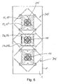
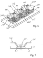
Anhand von Figur 5 bis 7 ist lediglich gezeigt, dass beispielsweise ein Dualband-Antennenarray, insbesondere für eine stationäre Mobilfunkantenne eine herkömmliche Strahleranordnung mit Strahlern 115 für ein höheres Frequenzband und Strahleranordnungen 215 zur Übertragung in einem niedrigeren Frequenzband umfassen kann. Die Strahleranordnung 215 zur Übertragung in dem niedrigeren Frequenzband besteht aus jeweils zwei Paaren parallel zueinander angeordneter Dipole 215' und 215", die so angeordnet sind, dass ein Dipolquadrat entsteht. In diesen Dipolquadraten zentrisch angeordnet sind in diesem Falle die für die Übertragung im höheren Frequenzband vorgesehenen Strahler, deren Dipolstrahler-Elemente auf einer zur Reflektorebene RE näheren Ebene liegen als die Dipolelemente 215' und 215" der im höheren Frequenzband strahlenden Strahlerelemente. Die Strahleranordnung 215 ist zum Senden und/oder Empfangen in dem niedrigeren Frequenzband vorgesehen (vorzugsweise kann es sich hierbei um ein Frequenzband handeln, mit dem beispielsweise mit halber Frequenz bezogen auf die Frequenz im höheren Frequenzband gearbeitet wird. Eine Beschränkung hierauf ist aber nicht zwingend notwendig). Sowohl die innen liegenden Strahler 115 wie die außen liegenden Strahler 215 sind so angeordnet und ausgerichtet, dass beide Strahlertypen in zwei senkrecht zueinander stehenden Polarisationsebenen strahlen, die im gezeigten Ausführungsbeispiel in einem Winkel von +45° bzw. -45° gegenüber einer Horizontal- oder Vertikalebene ausgerichtet sind.It is merely shown with reference to FIGS. 5 to 7 that, for example, a dual-band antenna array, in particular for a stationary mobile radio antenna, may comprise a conventional radiator arrangement with
Für die Übertragung im höheren Frequenzband sind dann zwischen den Zentren der beiden Strahleranordnungen 215 auf dem Reflektor 1 noch eine zusätzliche Strahleranordnung 115 angeordnet (insbesondere bei Übertragung in einem doppelt so hohem höheren Frequenzband als dem niedrigem Frequenzband ist somit also die Strahlerfolge und damit der Strahlerabstand zwischen den Strahlern für das höhere Frequenzband nur halb so groß wie für das nierigere Frequenzband). Wird dabei für die mittlere Strahleranordnung 115, d.h. also für die jeweils zwischen zwei für den niedrigen Frequenzbereich vorgesehene Strahleranordnung 215 liegende Strahleranordnung 115 jene Strahlformungs-Elemente 25 mit verwendet, wie sie bei dem Ausführungsbeispiel nach Figur 4 beschrieben worden sind, so ergibt sich eine Struktur entsprechend dem Beispiel gemäß Figur 5.For the transmission in the higher frequency band, an
Aus der entsprechenden Draufsicht gemäß Figur 6 lässt sich ersehen, dass die Strahlformungselemente 25 mit dem jeweiligen Tragabschnitt 25a und dem sich daran anschließenden Wirkabschnitt 25b in diesem Ausführungsbeispiel so geformt sind, dass der jeweilige Tragabschnitt 25a dem einen Teil des Trägers oder der Symmetrierung 17 mit einer entsprechenden Dipolanordnung für die in dem niedrigeren Frequenzband strahlenden Strahleranordnung 115 und der sich dann an den Tragabschnitt 25a anschließenden Wirkabschnitt 25b einer jeweils zugehörigen Dipolhälfte 215' einer benachbarten Strahleranordnung 215 entspricht, also vorzugsweise parallel dazu verlaufend ausgerichtet ist. Dabei ist also der Tragabschnitt 25'a im Wesentlichen in gleicher Länge, gleicher Ausrichtung und Steigung parallel zu dem einen Teil des Tragabschnittes oder der Symmetrierung 17' und der weitere Tragabschnitt 25"a in entsprechender, in Draufsicht um 90° versetzt liegender Ausrichtung und ansonsten gleicher Steigung und ähnlicher oder vergleichbarer Länge wie der zugehörige Teil des Tragabschnittes oder der Symmetrierung 17" der Strahler 215 angeordnet und positioniert, also auch im gleichen Abstand vom vertikalen Seitenrand 1' des Reflektors 1 bzw. im gleichen Seitenabstand von einem der mittleren senkrecht zur Reflektorebene verlaufenden Vertikalebene etc. In diesem Ausführungsbeispiel sind also die Wirkabschnitte 25b in einer Wirkebene WE parallel zum Reflektor angeordnet, in der auch die Dipolelemente 215' der für das niedrigere Frequenzband vorgesehenen Dipolstrahler 215 zu liegen kommen. Auch die Länge der Wirkabschnitte 25b entspricht in etwa der Länge der jeweiligen Dipolhälfte für das niedrigere Frequenzband oder weicht um weniger als 40%, insbesondere weniger als 30%, weniger als 20% oder sogar weniger als 10% davon ab. Schließlich ist auch die Anordnung der Wirkabschnitte in Relation zum Reflektor vergleichbar der Anordnung der Dipolhälften der benachbarten Strahler für die Übertragung in dem niedrigen Frequenzband. Mit anderen Worten sind die Wirkabschnitte oberhalb des Reflektors so angeordnet, dass beispielsweise die Dipolhälfte 215" etwa im gleichen Abstand von der benachbarten Seitenbegrenzung in 1' des Reflektors beginnt und endet, in welchem auch die entsprechend parallele Dipolhälfte 215" des Strahlerelementes für das höhere Frequenzband ebenfalls beginnt bzw. endet. Entsprechend ist für den jeweils dazu senkrecht stehenden zweiten Wirkabschnitt 25b' entsprechend gleiche Relativlage in Querrichtung des Reflektors angeordnet ist, wie die parallele Dipolhälfte 215' eines benachbarten Strahlers für das niedrigere Frequenzband.From the corresponding plan view according to FIG. 6, it can be seen that the beam-shaping
Hierdurch lassen sich besonders günstige Ergebnisse realisieren, da hierdurch nicht nur eine Formung des Fernfelddiagramms bei einer, sondern auch bei mehreren Polarisationen möglich ist und durch die Verwendung der entsprechenden Strahlformungs-Elemente 25 zudem eine Verbesserung der Isolation zwischen den Polarisationen und damit eine Verbesserung der Anpassung des jeweils für die höheren Frequenzen aktiven Elementes realisierbar ist.In this way, particularly favorable results can be achieved, since not only is it possible to shape the far-field diagram in one but also in the case of multiple polarizations and, by using the corresponding beam-shaping
Claims (14)
- Antenna having the following features:- having a reflector (1),- having an antenna element arrangement which has at least one antenna element (115, 215) for operation in two polarization planes (PE),- having at least four passive, electrically conductive elements, which are at least indirectly electrically conductively connected or electrically capacitively coupled to the reflector (1) ,characterized by the following further features:- the passive and electrically conductive elements comprise beamforming elements (25),- the at least four beamforming elements (25) that are provided are subdivided into at least two sections, specifically a mounting section (25a) and an operating section (25b), which is connected to the area of the mounting section (25a) located further away from the reflector (1),- the operating section (25b) lies on an operating plane (WE), which runs parallel to the reflector (1) , or differs from being parallel to it by less than ± 20°, at least in the area of the beamforming element (25) and/or of the antenna element (15, 115, 215) to be influenced via it,- the length of the operating section (25b) is between 0.2 λ and 1.0 λ,- the operating section (25b) or the operating plane (WE) is at a distance from the reflector (1) in the area of the operating section (25b), which distance is greater than or equal to 0.2 λ and is less than or equal to 1.5 λ,- the length of the mounting section (25a) is shorter than twice the wavelength 2 λ, where lambda (λ) is a wavelength of the frequency band to be transmitted,- the operating section (25b) is aligned parallel to (or differs by less than ± 20° from being parallel to) the associated polarization plane (PE) of the antenna element (115, 215) to be influenced via it,- the length of the mounting section (25a) is greater than the distance between the operating section (25b) and the reflector (1), and- the at least four mounting sections (25a) which are provided are arranged with the associated operating sections (25b) such that in each case two mounting sections (25a) run away from one another in the direction of the operating plane (WE), starting from the plane of the reflector (1), and the operating sections (25b) which are adjacent to the upper end of the mounting sections (25a) run towards one another again, on a common operating plane (WE).
- Antenna according to Claim 1, characterized in that the material thickness or the cross-sectional size of the mounting section (25a) and/or of the operating section (25b) is less than 0.1 λ, where lambda is the wavelength of the frequency band to be transmitted.
- Antenna according to Claim 1 or 2, characterized in that the mounting section (25a) lies at least essentially on a polarization plane (PE) of the antenna element arrangement.
- Antenna according to one of Claims 1 to 3, characterized in that the foot point (25c) of the mounting section (25a) as well as its transition area or transition point (25d) which is located at a distance from the reflector (1) and at which the operating section (25b) starts, is located at least approximately on the same polarization plane (PE) as the antenna element (15, 115, 215).
- Antenna according to one of Claims 1 to 4, characterized in that at least two beamforming elements (25) are provided for each polarization.
- Antenna according to one of Claims 1 to 5, characterized in that at least one operating section (25b) runs parallel to one of the two mutually perpendicular polarization planes (PE) and at least one further operating section (25b) runs parallel to the other polarization plane (PE).
- Antenna according to one of Claims 1 to 6, characterized in that the mounting section (25a) which is associated with a beamforming element (25) is parallel to one of the two mutually perpendicular polarization planes (PE), and in that the operating section (25b) which is held via this mounting section (25a) runs parallel to the other polarization plane (PE), which is at right angles thereto.
- Antenna according to one of Claims 1 to 7, characterized in that the operating section (25b) is aligned at right angles, or at least approximately at right angles, to the mounting section (25a) on which it is mounted.
- Antenna according to one of Claims 1 to 8, characterized in that, in a plan view of a dual-band or multiband antenna, at least parts of the operating sections (25b) are arranged such that they are located at least approximately at the same lateral distance from the side boundary (1') of the reflector (1) as the associated parallel dipole halves (215', 215") of adjacent antenna elements (215) for transmission in a lower frequency band.
- Antenna according to one of Claims 1 to 9, characterized in that the operating sections (25b, 25b', 25b") are arranged parallel to the dipole halves (215', 215") of adjacent antenna elements (215) which are provided for transmission in a lower frequency band.
- Antenna according to Claim 9 or 10, characterized in that the operating sections (25b) lie on an operating plane (WE) which corresponds to the antenna element plane of the antenna elements (215) which emit in a lower frequency band.
- Antenna according to one of Claims 1 to 11, characterized in that the operating section (25b) is aligned such that it is copolar to the respective antenna element (215) to be influenced.
- Antenna according to one of Claims 1 to 12, characterized in that the antenna is a stationary mobile radio antenna.
- Antenna according to one of Claims 1 to 13, characterized in that the mounting sections (25'a, 25" a) and/or the operating sections (25b, 25b', 25b") are arranged at the same distance from a vertical plane which runs centrally with respect to the reflector (1), and at right angles to the reflector plane.
Applications Claiming Priority (2)
| Application Number | Priority Date | Filing Date | Title |
|---|---|---|---|
| DE102004025904A DE102004025904B4 (en) | 2004-05-27 | 2004-05-27 | antenna |
| PCT/EP2005/005456 WO2005119835A1 (en) | 2004-05-27 | 2005-05-19 | Mobile radio antenna with beam-forming element |
Publications (2)
| Publication Number | Publication Date |
|---|---|
| EP1749331A1 EP1749331A1 (en) | 2007-02-07 |
| EP1749331B1 true EP1749331B1 (en) | 2008-01-30 |
Family
ID=34969022
Family Applications (1)
| Application Number | Title | Priority Date | Filing Date |
|---|---|---|---|
| EP05745719A Not-in-force EP1749331B1 (en) | 2004-05-27 | 2005-05-19 | Mobile radio antenna with beam-forming element |
Country Status (7)
| Country | Link |
|---|---|
| US (1) | US7075498B2 (en) |
| EP (1) | EP1749331B1 (en) |
| CN (1) | CN1702913B (en) |
| AT (1) | ATE385348T1 (en) |
| DE (2) | DE102004025904B4 (en) |
| ES (1) | ES2300022T3 (en) |
| WO (1) | WO2005119835A1 (en) |
Families Citing this family (19)
| Publication number | Priority date | Publication date | Assignee | Title |
|---|---|---|---|---|
| WO2006024516A1 (en) * | 2004-08-31 | 2006-03-09 | Fractus, S.A. | Slim multi-band antenna array for cellular base stations |
| US7180469B2 (en) * | 2005-06-29 | 2007-02-20 | Cushcraft Corporation | System and method for providing antenna radiation pattern control |
| US7701409B2 (en) | 2005-06-29 | 2010-04-20 | Cushcraft Corporation | System and method for providing antenna radiation pattern control |
| TWM284087U (en) * | 2005-08-26 | 2005-12-21 | Aonvision Technology Corp | Broadband planar dipole antenna |
| ATE544194T1 (en) | 2005-10-14 | 2012-02-15 | Fractus Sa | SLIM TRIPLE BAND ANTENNA ARRAY FOR CELLULAR BASE STATIONS |
| KR100883408B1 (en) * | 2006-09-11 | 2009-03-03 | 주식회사 케이엠더블유 | Dual-band dual-polarized base station antenna for mobile communication |
| CN101425626B (en) * | 2007-10-30 | 2013-10-16 | 京信通信系统(中国)有限公司 | Wide-band annular dual polarized radiating element and linear array antenna |
| EP2073309B1 (en) * | 2007-12-21 | 2015-02-25 | Alcatel Lucent | Dual polarised radiating element for cellular base station antennas |
| EP2346114B1 (en) * | 2008-09-22 | 2016-01-27 | KMW Inc. | Dual-frequency / polarization antenna for mobile-communications base station |
| CN101964447B (en) * | 2010-10-14 | 2013-01-16 | 西北工业大学 | Vertical polarization wideband dipole antenna |
| CN102299398B (en) * | 2011-05-20 | 2013-12-25 | 广东通宇通讯股份有限公司 | Dual-frequency dual-polarized antenna |
| US9461370B2 (en) | 2012-03-19 | 2016-10-04 | Galtronics Corporation, Ltd. | Multiple-input multiple-output antenna and broadband dipole radiating element therefore |
| WO2014174510A1 (en) * | 2013-04-22 | 2014-10-30 | Galtronics Corporation Ltd. | Multiband antenna and slotted ground plane therefore |
| KR101574495B1 (en) * | 2013-08-13 | 2015-12-04 | 주식회사 에이스테크놀로지 | Wideband Base Station Antenna Radiator |
| CN203813033U (en) * | 2013-12-23 | 2014-09-03 | 华为技术有限公司 | Multi-frequency array antenna |
| CN104600439B (en) * | 2014-12-31 | 2018-03-13 | 广东通宇通讯股份有限公司 | Multifrequency dual polarized antenna |
| US11611143B2 (en) | 2020-03-24 | 2023-03-21 | Commscope Technologies Llc | Base station antenna with high performance active antenna system (AAS) integrated therein |
| DE202021106120U1 (en) | 2020-03-24 | 2021-12-14 | Commscope Technologies Llc | Radiating elements with angled feed shafts and base station antennas including the same |
| DE202021003761U1 (en) | 2020-03-24 | 2022-03-25 | Commscope Technologies Llc | Base station antennas with an active antenna module and associated devices |
Family Cites Families (13)
| Publication number | Priority date | Publication date | Assignee | Title |
|---|---|---|---|---|
| GB982155A (en) * | 1962-08-21 | 1965-02-03 | Marconi Co Ltd | Improvements in or relating to aerial systems |
| KR0185962B1 (en) * | 1995-03-03 | 1999-05-15 | 구관영 | Antenna |
| US5629713A (en) * | 1995-05-17 | 1997-05-13 | Allen Telecom Group, Inc. | Horizontally polarized antenna array having extended E-plane beam width and method for accomplishing beam width extension |
| DE19627015C2 (en) * | 1996-07-04 | 2000-07-13 | Kathrein Werke Kg | Antenna field |
| SE508537C2 (en) | 1997-02-14 | 1998-10-12 | Ericsson Telefon Ab L M | Double-polarized antenna for receiving and transmitting electromagnetic signals |
| DE19722742C2 (en) * | 1997-05-30 | 2002-07-18 | Kathrein Werke Kg | Dual polarized antenna arrangement |
| FR2766626B1 (en) | 1997-07-28 | 1999-10-01 | Alsthom Cge Alcatel | CROSS POLARIZATION DIRECTIONAL ANTENNA SYSTEM |
| DE19823750A1 (en) * | 1998-05-27 | 1999-12-09 | Kathrein Werke Kg | Antenna array with several primary radiator modules arranged vertically one above the other |
| DE19823749C2 (en) | 1998-05-27 | 2002-07-11 | Kathrein Werke Kg | Dual polarized multi-range antenna |
| DE19860121A1 (en) * | 1998-12-23 | 2000-07-13 | Kathrein Werke Kg | Dual polarized dipole emitter |
| DE19931907C2 (en) | 1999-07-08 | 2001-08-09 | Kathrein Werke Kg | antenna |
| WO2002041451A1 (en) * | 2000-11-17 | 2002-05-23 | Ems Technologies, Inc. | Radio frequency isolation card |
| DE10064129B4 (en) * | 2000-12-21 | 2006-04-20 | Kathrein-Werke Kg | Antenna, in particular mobile radio antenna |
-
2004
- 2004-05-27 DE DE102004025904A patent/DE102004025904B4/en not_active Expired - Fee Related
- 2004-08-19 US US10/921,292 patent/US7075498B2/en not_active Expired - Fee Related
- 2004-09-07 CN CN200410076812.0A patent/CN1702913B/en not_active Expired - Fee Related
-
2005
- 2005-05-19 DE DE502005002729T patent/DE502005002729D1/en active Active
- 2005-05-19 ES ES05745719T patent/ES2300022T3/en active Active
- 2005-05-19 AT AT05745719T patent/ATE385348T1/en not_active IP Right Cessation
- 2005-05-19 EP EP05745719A patent/EP1749331B1/en not_active Not-in-force
- 2005-05-19 WO PCT/EP2005/005456 patent/WO2005119835A1/en active IP Right Grant
Also Published As
| Publication number | Publication date |
|---|---|
| CN1702913B (en) | 2010-12-01 |
| ATE385348T1 (en) | 2008-02-15 |
| US20050264463A1 (en) | 2005-12-01 |
| CN1702913A (en) | 2005-11-30 |
| DE102004025904B4 (en) | 2007-04-05 |
| WO2005119835A1 (en) | 2005-12-15 |
| DE502005002729D1 (en) | 2008-03-20 |
| US7075498B2 (en) | 2006-07-11 |
| DE102004025904A1 (en) | 2005-12-22 |
| EP1749331A1 (en) | 2007-02-07 |
| ES2300022T3 (en) | 2008-06-01 |
Similar Documents
| Publication | Publication Date | Title |
|---|---|---|
| EP1749331B1 (en) | Mobile radio antenna with beam-forming element | |
| EP1470615B1 (en) | Dual-polarized radiating assembly | |
| EP0848862B1 (en) | Antenna array | |
| EP2929589B1 (en) | Dual polarized, omnidirectional antenna | |
| DE10064129B4 (en) | Antenna, in particular mobile radio antenna | |
| EP0916169B1 (en) | Antenna system | |
| DE19829714B4 (en) | Antenna with dual polarization | |
| EP3025395B1 (en) | Wideband antenna array | |
| WO2006058658A1 (en) | Dual-band mobile radio antenna | |
| DE10012809A1 (en) | Dual polarized dipole array antenna has supply cable fed to supply point on one of two opposing parallel dipoles, connecting cable to supply point on opposing dipole | |
| EP3306742A1 (en) | Mobile radio antenna | |
| EP1082781A1 (en) | Antenna array with several vertically superposed primary radiator modules | |
| EP1964205A1 (en) | Dual-polarized antenna having longitudinal or transverse webs | |
| DE102007060083A1 (en) | Multiple gaps-multi bands-antenna-array has two groups provided by emitters or emitter modules, where emitters are formed for transmitting or receiving in common frequency band | |
| EP1525642B1 (en) | Two-dimensional antenna array | |
| WO2019162345A1 (en) | Multiband antenna array for mobile radio applications | |
| WO2016050336A1 (en) | Multi-band radiator system | |
| DE202004008770U1 (en) | Mobile radio base station antenna element has conducting main reflector, dual polarized radiator and cross shaped passive subreflector | |
| EP1056155A2 (en) | Antenna for mobile, in particlar for a vehicle, with at least one circular and one linear polarisation , preferably vertical polarisation | |
| DE202004013971U1 (en) | Antenna for a mobile radio, with dipoles, has a dielectric body over the reflector and/or radiator with a longitudinal decoupling element |
Legal Events
| Date | Code | Title | Description |
|---|---|---|---|
| PUAI | Public reference made under article 153(3) epc to a published international application that has entered the european phase |
Free format text: ORIGINAL CODE: 0009012 |
|
| 17P | Request for examination filed |
Effective date: 20060921 |
|
| AK | Designated contracting states |
Kind code of ref document: A1 Designated state(s): AT BE BG CH CY CZ DE DK EE ES FI FR GB GR HU IE IS IT LI LT LU MC NL PL PT RO SE SI SK TR |
|
| 17Q | First examination report despatched |
Effective date: 20070221 |
|
| GRAP | Despatch of communication of intention to grant a patent |
Free format text: ORIGINAL CODE: EPIDOSNIGR1 |
|
| DAX | Request for extension of the european patent (deleted) | ||
| GRAS | Grant fee paid |
Free format text: ORIGINAL CODE: EPIDOSNIGR3 |
|
| GRAA | (expected) grant |
Free format text: ORIGINAL CODE: 0009210 |
|
| AK | Designated contracting states |
Kind code of ref document: B1 Designated state(s): AT BE BG CH CY CZ DE DK EE ES FI FR GB GR HU IE IS IT LI LT LU MC NL PL PT RO SE SI SK TR |
|
| REG | Reference to a national code |
Ref country code: GB Ref legal event code: FG4D Free format text: NOT ENGLISH |
|
| GBT | Gb: translation of ep patent filed (gb section 77(6)(a)/1977) |
Effective date: 20080130 |
|
| REG | Reference to a national code |
Ref country code: CH Ref legal event code: EP |
|
| REG | Reference to a national code |
Ref country code: IE Ref legal event code: FG4D Free format text: LANGUAGE OF EP DOCUMENT: GERMAN |
|
| REF | Corresponds to: |
Ref document number: 502005002729 Country of ref document: DE Date of ref document: 20080320 Kind code of ref document: P |
|
| REG | Reference to a national code |
Ref country code: ES Ref legal event code: FG2A Ref document number: 2300022 Country of ref document: ES Kind code of ref document: T3 |
|
| PG25 | Lapsed in a contracting state [announced via postgrant information from national office to epo] |
Ref country code: FI Free format text: LAPSE BECAUSE OF FAILURE TO SUBMIT A TRANSLATION OF THE DESCRIPTION OR TO PAY THE FEE WITHIN THE PRESCRIBED TIME-LIMIT Effective date: 20080130 Ref country code: IS Free format text: LAPSE BECAUSE OF FAILURE TO SUBMIT A TRANSLATION OF THE DESCRIPTION OR TO PAY THE FEE WITHIN THE PRESCRIBED TIME-LIMIT Effective date: 20080530 |
|
| NLV1 | Nl: lapsed or annulled due to failure to fulfill the requirements of art. 29p and 29m of the patents act | ||
| ET | Fr: translation filed | ||
| PG25 | Lapsed in a contracting state [announced via postgrant information from national office to epo] |
Ref country code: PL Free format text: LAPSE BECAUSE OF FAILURE TO SUBMIT A TRANSLATION OF THE DESCRIPTION OR TO PAY THE FEE WITHIN THE PRESCRIBED TIME-LIMIT Effective date: 20080130 Ref country code: SI Free format text: LAPSE BECAUSE OF FAILURE TO SUBMIT A TRANSLATION OF THE DESCRIPTION OR TO PAY THE FEE WITHIN THE PRESCRIBED TIME-LIMIT Effective date: 20080130 Ref country code: PT Free format text: LAPSE BECAUSE OF FAILURE TO SUBMIT A TRANSLATION OF THE DESCRIPTION OR TO PAY THE FEE WITHIN THE PRESCRIBED TIME-LIMIT Effective date: 20080630 |
|
| REG | Reference to a national code |
Ref country code: IE Ref legal event code: FD4D |
|
| PG25 | Lapsed in a contracting state [announced via postgrant information from national office to epo] |
Ref country code: SK Free format text: LAPSE BECAUSE OF FAILURE TO SUBMIT A TRANSLATION OF THE DESCRIPTION OR TO PAY THE FEE WITHIN THE PRESCRIBED TIME-LIMIT Effective date: 20080130 Ref country code: NL Free format text: LAPSE BECAUSE OF FAILURE TO SUBMIT A TRANSLATION OF THE DESCRIPTION OR TO PAY THE FEE WITHIN THE PRESCRIBED TIME-LIMIT Effective date: 20080130 Ref country code: IE Free format text: LAPSE BECAUSE OF FAILURE TO SUBMIT A TRANSLATION OF THE DESCRIPTION OR TO PAY THE FEE WITHIN THE PRESCRIBED TIME-LIMIT Effective date: 20080130 Ref country code: DK Free format text: LAPSE BECAUSE OF FAILURE TO SUBMIT A TRANSLATION OF THE DESCRIPTION OR TO PAY THE FEE WITHIN THE PRESCRIBED TIME-LIMIT Effective date: 20080130 Ref country code: CZ Free format text: LAPSE BECAUSE OF FAILURE TO SUBMIT A TRANSLATION OF THE DESCRIPTION OR TO PAY THE FEE WITHIN THE PRESCRIBED TIME-LIMIT Effective date: 20080130 Ref country code: SE Free format text: LAPSE BECAUSE OF FAILURE TO SUBMIT A TRANSLATION OF THE DESCRIPTION OR TO PAY THE FEE WITHIN THE PRESCRIBED TIME-LIMIT Effective date: 20080430 |
|
| PG25 | Lapsed in a contracting state [announced via postgrant information from national office to epo] |
Ref country code: RO Free format text: LAPSE BECAUSE OF FAILURE TO SUBMIT A TRANSLATION OF THE DESCRIPTION OR TO PAY THE FEE WITHIN THE PRESCRIBED TIME-LIMIT Effective date: 20080130 |
|
| BERE | Be: lapsed |
Owner name: KATHREIN-WERKE K.G. Effective date: 20080531 |
|
| PLBE | No opposition filed within time limit |
Free format text: ORIGINAL CODE: 0009261 |
|
| STAA | Information on the status of an ep patent application or granted ep patent |
Free format text: STATUS: NO OPPOSITION FILED WITHIN TIME LIMIT |
|
| PG25 | Lapsed in a contracting state [announced via postgrant information from national office to epo] |
Ref country code: MC Free format text: LAPSE BECAUSE OF NON-PAYMENT OF DUE FEES Effective date: 20080531 |
|
| 26N | No opposition filed |
Effective date: 20081031 |
|
| PG25 | Lapsed in a contracting state [announced via postgrant information from national office to epo] |
Ref country code: LT Free format text: LAPSE BECAUSE OF FAILURE TO SUBMIT A TRANSLATION OF THE DESCRIPTION OR TO PAY THE FEE WITHIN THE PRESCRIBED TIME-LIMIT Effective date: 20080130 |
|
| PG25 | Lapsed in a contracting state [announced via postgrant information from national office to epo] |
Ref country code: BE Free format text: LAPSE BECAUSE OF NON-PAYMENT OF DUE FEES Effective date: 20080531 |
|
| PG25 | Lapsed in a contracting state [announced via postgrant information from national office to epo] |
Ref country code: BG Free format text: LAPSE BECAUSE OF FAILURE TO SUBMIT A TRANSLATION OF THE DESCRIPTION OR TO PAY THE FEE WITHIN THE PRESCRIBED TIME-LIMIT Effective date: 20080430 Ref country code: EE Free format text: LAPSE BECAUSE OF FAILURE TO SUBMIT A TRANSLATION OF THE DESCRIPTION OR TO PAY THE FEE WITHIN THE PRESCRIBED TIME-LIMIT Effective date: 20080130 |
|
| PG25 | Lapsed in a contracting state [announced via postgrant information from national office to epo] |
Ref country code: CY Free format text: LAPSE BECAUSE OF FAILURE TO SUBMIT A TRANSLATION OF THE DESCRIPTION OR TO PAY THE FEE WITHIN THE PRESCRIBED TIME-LIMIT Effective date: 20080130 |
|
| PG25 | Lapsed in a contracting state [announced via postgrant information from national office to epo] |
Ref country code: AT Free format text: LAPSE BECAUSE OF NON-PAYMENT OF DUE FEES Effective date: 20080519 Ref country code: IT Free format text: LAPSE BECAUSE OF FAILURE TO SUBMIT A TRANSLATION OF THE DESCRIPTION OR TO PAY THE FEE WITHIN THE PRESCRIBED TIME-LIMIT Effective date: 20080130 |
|
| REG | Reference to a national code |
Ref country code: CH Ref legal event code: PL |
|
| PG25 | Lapsed in a contracting state [announced via postgrant information from national office to epo] |
Ref country code: CH Free format text: LAPSE BECAUSE OF NON-PAYMENT OF DUE FEES Effective date: 20090531 Ref country code: LI Free format text: LAPSE BECAUSE OF NON-PAYMENT OF DUE FEES Effective date: 20090531 |
|
| PG25 | Lapsed in a contracting state [announced via postgrant information from national office to epo] |
Ref country code: LU Free format text: LAPSE BECAUSE OF NON-PAYMENT OF DUE FEES Effective date: 20080519 Ref country code: HU Free format text: LAPSE BECAUSE OF FAILURE TO SUBMIT A TRANSLATION OF THE DESCRIPTION OR TO PAY THE FEE WITHIN THE PRESCRIBED TIME-LIMIT Effective date: 20080731 |
|
| PG25 | Lapsed in a contracting state [announced via postgrant information from national office to epo] |
Ref country code: TR Free format text: LAPSE BECAUSE OF FAILURE TO SUBMIT A TRANSLATION OF THE DESCRIPTION OR TO PAY THE FEE WITHIN THE PRESCRIBED TIME-LIMIT Effective date: 20080130 |
|
| PG25 | Lapsed in a contracting state [announced via postgrant information from national office to epo] |
Ref country code: GR Free format text: LAPSE BECAUSE OF FAILURE TO SUBMIT A TRANSLATION OF THE DESCRIPTION OR TO PAY THE FEE WITHIN THE PRESCRIBED TIME-LIMIT Effective date: 20080501 |
|
| REG | Reference to a national code |
Ref country code: FR Ref legal event code: PLFP Year of fee payment: 12 |
|
| PGFP | Annual fee paid to national office [announced via postgrant information from national office to epo] |
Ref country code: ES Payment date: 20160523 Year of fee payment: 12 Ref country code: GB Payment date: 20160523 Year of fee payment: 12 |
|
| REG | Reference to a national code |
Ref country code: FR Ref legal event code: PLFP Year of fee payment: 13 |
|
| PGFP | Annual fee paid to national office [announced via postgrant information from national office to epo] |
Ref country code: DE Payment date: 20170522 Year of fee payment: 13 Ref country code: FR Payment date: 20170522 Year of fee payment: 13 |
|
| GBPC | Gb: european patent ceased through non-payment of renewal fee |
Effective date: 20170519 |
|
| PG25 | Lapsed in a contracting state [announced via postgrant information from national office to epo] |
Ref country code: GB Free format text: LAPSE BECAUSE OF NON-PAYMENT OF DUE FEES Effective date: 20170519 |
|
| REG | Reference to a national code |
Ref country code: ES Ref legal event code: FD2A Effective date: 20180703 |
|
| REG | Reference to a national code |
Ref country code: DE Ref legal event code: R082 Ref document number: 502005002729 Country of ref document: DE Representative=s name: FLACH BAUER STAHL PATENTANWAELTE PARTNERSCHAFT, DE |
|
| PG25 | Lapsed in a contracting state [announced via postgrant information from national office to epo] |
Ref country code: ES Free format text: LAPSE BECAUSE OF NON-PAYMENT OF DUE FEES Effective date: 20170520 |
|
| REG | Reference to a national code |
Ref country code: DE Ref legal event code: R119 Ref document number: 502005002729 Country of ref document: DE |
|
| REG | Reference to a national code |
Ref country code: DE Ref legal event code: R082 Ref document number: 502005002729 Country of ref document: DE Representative=s name: FLACH BAUER STAHL PATENTANWAELTE PARTNERSCHAFT, DE Ref country code: DE Ref legal event code: R081 Ref document number: 502005002729 Country of ref document: DE Owner name: KATHREIN SE, DE Free format text: FORMER OWNER: KATHREIN-WERKE KG, 83022 ROSENHEIM, DE |
|
| PG25 | Lapsed in a contracting state [announced via postgrant information from national office to epo] |
Ref country code: FR Free format text: LAPSE BECAUSE OF NON-PAYMENT OF DUE FEES Effective date: 20180531 Ref country code: DE Free format text: LAPSE BECAUSE OF NON-PAYMENT OF DUE FEES Effective date: 20181201 |