EP0848862B1 - Antenna array - Google Patents
Antenna array Download PDFInfo
- Publication number
- EP0848862B1 EP0848862B1 EP97927140A EP97927140A EP0848862B1 EP 0848862 B1 EP0848862 B1 EP 0848862B1 EP 97927140 A EP97927140 A EP 97927140A EP 97927140 A EP97927140 A EP 97927140A EP 0848862 B1 EP0848862 B1 EP 0848862B1
- Authority
- EP
- European Patent Office
- Prior art keywords
- antenna array
- radiating element
- array according
- decoupling structure
- decoupling
- Prior art date
- Legal status (The legal status is an assumption and is not a legal conclusion. Google has not performed a legal analysis and makes no representation as to the accuracy of the status listed.)
- Expired - Lifetime
Links
Images

Classifications
-
- H—ELECTRICITY
- H01—ELECTRIC ELEMENTS
- H01Q—ANTENNAS, i.e. RADIO AERIALS
- H01Q1/00—Details of, or arrangements associated with, antennas
- H01Q1/52—Means for reducing coupling between antennas; Means for reducing coupling between an antenna and another structure
- H01Q1/521—Means for reducing coupling between antennas; Means for reducing coupling between an antenna and another structure reducing the coupling between adjacent antennas
- H01Q1/523—Means for reducing coupling between antennas; Means for reducing coupling between an antenna and another structure reducing the coupling between adjacent antennas between antennas of an array
-
- H—ELECTRICITY
- H01—ELECTRIC ELEMENTS
- H01Q—ANTENNAS, i.e. RADIO AERIALS
- H01Q21/00—Antenna arrays or systems
- H01Q21/24—Combinations of antenna units polarised in different directions for transmitting or receiving circularly and elliptically polarised waves or waves linearly polarised in any direction
- H01Q21/26—Turnstile or like antennas comprising arrangements of three or more elongated elements disposed radially and symmetrically in a horizontal plane about a common centre
Definitions
- Dual polarized antenna arrays i.e. radiator arrangements, which dipoles, slots or planar radiator elements for simultaneous reception or simultaneous emission electromagnetic waves with two orthogonal linear Polarizations that are separate and separate from each other decoupled outputs are sufficient known.
- radiator arrangements can, for example of several elements in the form of dipoles, Slits or planar emitter elements exist as they do for example from EP 0 685 900 A1 or from the prior publication "Antennas", second part, by Adolf Heilmann, Bibliographical Institute Mannheim / Vienna / Zurich, 1970 University pocket book publisher, pages 47 to 50, known are.
- This applies to omnidirectional spotlights for example with horizontal polarization the shapes of a dipole square or a dipole cross known, which is a coupling between the two systems offset by 90 ° exhibit.
- radiator modules To increase the antenna gain, it is possible to use several these radiator modules to antenna fields, so-called arrays, interconnect. It is per sending and receiving station not uncommon, ten or more radiator modules interconnect to an array.
- the spotlight modules can be arranged side by side or one below the other.
- the direction in which the emitter modules are straight or inclined should be arranged next to or below each other be referred to as the alignment of the antenna array.
- the object of the present invention is therefore a To create X-polarized antenna array, which is preferred broadband a high decoupling between the resulting Has feed systems for both polarizations.
- Decoupling device with a new type of decoupling structure is provided.
- This decoupling structure is completely different to the z.
- the invention Decoupling structure has a longitudinal extension on, in the vertical mounting direction two side by side Arrays arranged (basically also with horizontal Direction of attachment of two arrays arranged side by side) is aligned. In other words, they are already good Results with a vertically aligned X-polarized Array e.g. then achieved when between two on top of each other arranged radiator modules in the vertical direction extending longitudinal rod is provided.
- a longitudinal slot or another decoupling structure with an elongated recess or extension introduced is.
- the conductive ones cross-shaped structural elements of the decoupling structure connected at their intersection.
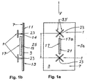
- the first is the embodiment received according to Figures 1a and 1b.
- a dipole square for example a square structure have
- the radiator modules 1 are in front of a reflector 7 Dipoles at a distance from the reflector 7 sitting on it assembled.
- the reflector 7 by a metallization 9 on a circuit board 11 formed on the back of a feed network 13th is located, which separates the individual radiator modules interconnects for the respective polarization.
- the dipoles 3 are compared via a so-called symmetrization 14 the circuit board 11 held mechanically and electrically contacted, d. H. so fed from the board 13.
- the longitudinal or extension component of the decoupling structure 17, which in the following also partially as a decoupling structural element 17 is according to the Embodiment according to Figure 1a or 1b larger than at least 1/4 of the distance between the two neighboring ones Centers or base points 23 of the radiator modules or corresponds 1/4 of this distance.
- the longitudinal component is preferably more than 40 or 50% of the said Spotlight module distance 25.
- the rod 17a shown is a short distance above the Reflector surface 7 is arranged and is a spacer 18 on the reflector 7, i.e. mechanically held by the circuit board 11 and with the reflector 7 electrically contacted.
- the decoupling structure could but also further than the double dipole arrangement 3 be removed from the reflector surface 7, wherein however then influences on the radiation diagram at good decoupling can be determined if the distance of the decoupling structure 17 from the reflector surface is more than half as far away as the dipoles the double dipole arrangement 3.
- the arrangement is preferred such that the conductive decoupling structure 17 in shape of the rod 17a not more than 1/8 to 1/4 wavelength is removed from the reflector plane.
- the arrangement can be such that the dipoles 3 'for example at a distance of 0.1 to 0.5 Wavelengths, preferably 0.2 to 0.3 wavelengths, in particular by 0.25 wavelengths, in front of the reflector surface sit, the decoupling structure in the form of the decoupling structure element 17a a distance of 0.015 up to 0.125 wavelengths, in particular 0.015 to 0.035 wavelengths (i.e. about 1/60 to 1/8, especially 1/60 to 1/30 of the wavelength), opposite the reflector surface 7 can have.
- the decoupling structure 17 is not in the form of a Rod, but in the form of a plan view of Figure 1a congruent to the rod shown there in the reflector surface 7 slot introduced.
- a conductive surface at a distance in front of the reflector surface in which a corresponding one Recess is introduced, which has a structure with a longitudinal extension, preferably parallel and in the area of the connection or mounting direction 21 lying.
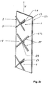
- the exemplary embodiment according to FIGS. 2a, 2b and 2c differs from the exemplary embodiment explained above in that for the decoupling structure 17 no rod extending in the connecting direction 21 17a, but a cross-shaped decoupling structural element 17b is used from two crossing bars.
- a schematic perspective illustration is shown in FIG. 2c of the embodiment shown in Figures 2a and 2b.
- the rods 27 are in this embodiment almost perpendicular to each other, the two rods almost parallel to the polarization planes, i.e. to the dipoles 3 'are aligned.
- the cruciform Decoupling structural element 17b with the rods 27 also conductive again, the two rods 27 in their intersection 29 are conductively connected.
- the longitudinal component in the connection or mounting direction 21 of the cross-shaped decoupling structure 17 thus formed 0.25 to 1 wavelength, for example, preferably 0.5 to 0.8 wavelengths, especially around 0.7 Wavelengths.
- the projection is under "longitudinal component" on the vertical, i.e. on the direct connecting line between two neighboring radiator modules in To understand the direction of cultivation. Because of the symmetrical Structure is the extension in the transverse direction to the direction of attachment 21 of the same length, but this does not have to be mandatory.
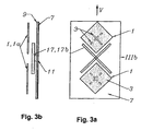
- Patch emitters 1a such as basically from the ITG technical report pre-publication 128 "antennas" (lectures of the ITG conference from April 12 to 15, 1994 in Dresden), VDE-Verlag GmbH, Berlin, Offenbach, pages 259 to 264 are known. It deals are aperture-coupled microstrip patch antennas with a cross slot or offset slot arrangement to receive two orthogonal linear Polarizations.
- the patch radiators 1a have square shapes in plan view Structure on and are with their slot arrangement each again aligned at a 45 ° angle to the vertical V in order to both + 45 ° and -45 ° polarizations received or to be able to send.
Description
Die Erfindung betrifft ein Antennenarray zum gleichzeitigen
Empfangen oder zur gleichzeitigen Abstrahlung elektromagnetischer
Wellen mit zwei linearen orthogonalen
Polarisationen nach dem Oberbegriff des Anspruches 1.The invention relates to an antenna array for simultaneous
Receive or for the simultaneous emission of electromagnetic
Waves with two linear orthogonal ones
Polarizations according to the preamble of
Dual polarisierte Antennenarrays, also Strahleranordnungen, welche Dipole, Schlitze oder planare Strahlerelemente zum gleichzeitigen Empfangen oder gleichzeitigen Abstrahlen elektromagnetischer Wellen mit zwei orthogonalen linearen Polarisationen, die getrennten und voneinander entkoppelten Ausgängen zugeführt werden, sind hinlänglich bekannt. Dabei können derartige Strahleranordnungen beispielsweise aus mehreren Elementen in Form von Dipolen, Schlitzen oder Planarstrahlerelementen bestehen, wie sie beispielweise aus der EP 0 685 900 A1 oder aus der Vorveröffentlichung "Antennen", zweiter Teil, von Adolf Heilmann, Bibliographisches Institut Mannheim/Wien/Zürich, 1970 Hochschultaschenbücherverlag, Seiten 47 bis 50, bekannt sind. Daraus sind beispielsweise bei Rundstrahlern mit horizontaler Polarisation die Formen eines Dipolquadrates oder eines Dipolkreuzes bekannt, welche eine Kopplung zwischen den beiden um 90° räumlich versetzten Systemen aufweisen.Dual polarized antenna arrays, i.e. radiator arrangements, which dipoles, slots or planar radiator elements for simultaneous reception or simultaneous emission electromagnetic waves with two orthogonal linear Polarizations that are separate and separate from each other decoupled outputs are sufficient known. Such radiator arrangements can, for example of several elements in the form of dipoles, Slits or planar emitter elements exist as they do for example from EP 0 685 900 A1 or from the prior publication "Antennas", second part, by Adolf Heilmann, Bibliographical Institute Mannheim / Vienna / Zurich, 1970 University pocket book publisher, pages 47 to 50, known are. This applies to omnidirectional spotlights, for example with horizontal polarization the shapes of a dipole square or a dipole cross known, which is a coupling between the two systems offset by 90 ° exhibit.
Zur Erhöhung der Richtwirkung werden derartige nachfolgend auch als Strahlermodule bezeichnete Strahleranordnungen üblicherweise vor einer reflektierenden Fläche, dem sog. Reflektor, angeordnet, wobei bei Planarantennen gleichzeitig eine metallische Schicht des Substrates als Reflektor fungieren kann.To increase the directivity, such are below also referred to as radiator modules usually in front of a reflective surface, the so-called Reflector, arranged, with planar antennas simultaneously a metallic layer of the substrate as a reflector can act.
Zur Erhöhung des Antennengewinns ist es möglich, mehrere dieser Strahlermodule zu Antennenfeldern, sog. Arrays, zusammenzuschalten. Pro Sende- und Empfangsstation ist es dabei durchaus nicht unüblich, zehn oder mehr Strahlermodule zu einem Array zusammenzuschalten. Die Strahlermodule können dabei neben- oder untereinander angeordnet werden. Die Richtung, in der die Strahlermodule gerade oder schräg neben- oder untereinander angeordnet werden, soll dabei als Ausrichtung des Antennenarrays bezeichnet werden.To increase the antenna gain, it is possible to use several these radiator modules to antenna fields, so-called arrays, interconnect. It is per sending and receiving station not uncommon, ten or more radiator modules interconnect to an array. The spotlight modules can be arranged side by side or one below the other. The direction in which the emitter modules are straight or inclined should be arranged next to or below each other be referred to as the alignment of the antenna array.
Als nachteilig erweist sich aber nunmehr, dass beim Zusammenschalten mehrerer Strahlermodule die resultierende Entkopplung der Arrays zwischen den zusammengeschalteten Strahlermodulen beider Polarisationen deutlich schlechter ausfällt als die des Strahlermoduls selbst. Diese nachteiligen Effekte treten vor allem dann auf, wenn die Ausrichtung des Antennenarrays nicht mit einer der beiden Polarisationsebenen zusammenfällt. Hauptsächlich tritt dieser Fall bei Antennenarrays auf, welche so aufgebaut sind, dass die Strahlermodule in Vertikalrichtung übereinander angeordnet sind, wobei die Strahlermodule so ausgerichtet sind, dass sie lineare Polarisationen mit einem Winkel von +45° und -45° bezogen auf die Vertikale empfangen oder abstrahlen. Derartige Antennenarrays mit von der Polarisationsebene abweichender Ausrichtung werden nachfolgend auch kurz als X-polarisierte Arrays bezeichnet.It has now proven to be disadvantageous that when interconnecting the result of several radiator modules Decoupling the arrays between the interconnected Radiator modules of both polarizations significantly worse fails than that of the radiator module itself. These disadvantage Effects occur especially when the alignment of the antenna array with one of the two Polarization planes coincide. Mainly kicks this case with antenna arrays, which are constructed in this way are that the radiator modules one above the other in the vertical direction are arranged, the radiator modules so aligned are that they have linear polarizations with a Receive angles of + 45 ° and -45 ° related to the vertical or blast. Such antenna arrays with from orientation deviating from the polarization plane hereinafter also referred to as X-polarized arrays.
Bei derartigen Arrays ist festzustellen, dass u.a. durch die fehlende Übereinstimmung der Ausrichtung des Arrays und der Polarisationsebenen sowie durch die schiefwinklige Lage der Polarisationsebenen zum Reflektor die benachbarten Module untereinander relativ stark verkoppeln. Als nicht ausreichend empfundene Entkopplungswerte von beispielsweise 20 bis 25 dB sind dabei keine Seltenheit.With such arrays, it should be noted that i.a. by the mismatch of alignment of the array and the polarization planes as well as the oblique angle Position of the polarization planes to the reflector the neighboring ones Couple modules relatively strongly. As decoupling values of, for example, not sufficiently felt 20 to 25 dB are not uncommon.
Da im Mobilfunkbereich bevorzugt die vertikale Polarisation genutzt wird, bietet dieser Antennentyp gegenüber dual polarisierten Antennen mit horizontaler und vertikaler Polarisation den Vorteil, dass auf beiden Polarisationen zur mobilen Station gesendet werden kann.Vertical polarization is preferred in the field of mobile communications is used, this antenna type offers dual polarized antennas with horizontal and vertical Polarization has the advantage of being on both polarizations can be sent to the mobile station.
Es sind bereits Antennenarrays vorgeschlagen worden, welche zur Verbesserung der Entkopplung zwischen den einzelnen Strahlern, d.h. den Strahlermodulen, Trennwände vorsehen, die also senkrecht zu der Anbau- oder Verbindungsrichtung oder -linie zwischen zwei benachbarten Strahlermodulen ausgerichtet sind. Versuche haben nunmehr ergeben, dass eine derartige Konstruktion bei X-polarisierten Arrays durch eine festzustellende Polarisationsdrehung meist sogar noch zu einer Verschlechterung der Entkopplung führt, insbesondere bei breitbandigen Antennen.Antenna arrays have already been proposed, which to improve the decoupling between the individual Emitters, i.e. the radiator modules, partitions provide, that is perpendicular to the direction of attachment or connection or line between two neighboring ones Radiator modules are aligned. Attempts have now reveal that such a construction in X-polarized Arrays by a polarization rotation to be determined usually even worsening Decoupling leads, especially with broadband antennas.
Schließlich ist auch bekannt, dass bei vertikal übereinander angeordneten Einzelstrahlern mit horizontaler Polarisation horizontal angeordnete Stäbe eine Verbesserung der Entkopplung zwischen den Einzelstrahler bewirken. Diese Verbesserung der Entkopplung betrifft jedoch nur Strahler der gleichen Polarisation und führt bei X-polarisierten Arrays (bei denen beispielsweise die vertikale Ausrichtung der Arrays, wie erwähnt, nicht mit den linearen Polarisationen von beispielsweise +45° und -45° übereinstimmt) meist zu keiner Verbesserung der Entkopplung zwischen den verschiedenen polarisierten Speisesystemen.Finally, it is also known that when stacked vertically arranged single radiators with horizontal polarization horizontally arranged bars an improvement cause the decoupling between the individual radiators. However, this improvement in decoupling only affects Emitter of the same polarization and leads to X-polarized Arrays (where, for example, the vertical Alignment of the arrays, as mentioned, not with the linear ones Polarizations of + 45 ° and -45 °, for example) mostly no improvement in the decoupling between the different polarized feeding systems.
Ein den vorstehend erläuterten Antennen entsprechendes Antennenarray ist beispielsweise auch aus der US 3 541 559 bekannt geworden. Das Antennenarray umfasst mehrere in einem Antennenfeld angeordnete, d.h. in mehreren horizontalen Reihen und vertikalen Spalten angeordnete, Strahlermodule, wobei jeweils zwischen zwei vertikal bzw. horizontal nebeneinander angeordneten Strahlermodulen ein stabförmiges Reflektorelement nach. Art eines parasitären Reflektors angeordnet ist. Dieses stabförmige parasitäre Reflektorelement ist jeweils quer zu der zwei benachbarte Strahlermodule verbindenden Verbindungslinie ausgerichtet. Diese parasitären Reflektorelemente dienen einer Strahlungsformung, die auch schon bei Verwendung eines einzigen Strahlermoduls wirksam ist.A corresponding to the antennas explained above Antenna array is also, for example, from US 3,541,559 known. The antenna array spans several in an antenna array, i.e. in several horizontal Radiator modules arranged in rows and vertical columns, being between two vertical and two horizontal radiator modules arranged side by side rod-shaped reflector element after. Kind of a parasitic Reflector is arranged. This rod-shaped parasitic Reflector element is transverse to the two adjacent Aligned connecting line connecting radiator modules. These parasitic reflector elements are used for radiation shaping, that even when using a single one Emitter module is effective.
Aufgabe der vorliegenden Erfindung ist es von daher, ein X-polarisiertes Antennenarray zu schaffen, welches bevorzugt breitbandig eine hohe Entkopplung zwischen den resultierenden Speisesystemen für beide Polarisationen besitzt.The object of the present invention is therefore a To create X-polarized antenna array, which is preferred broadband a high decoupling between the resulting Has feed systems for both polarizations.
Die Aufgabe wird erfindungsgemäß entsprechend den im Anspruch
1 angegebenen Merkmalen gelöst. Vorteilhafte Ausgestaltungen
der Erfindung sind in den Unteransprüchen angegeben.The task is according to the invention in accordance with the
Es kann als durchaus überraschend bezeichnet werden, dass mit der erfindungsgemäßen Lösung eine gegenüber dem Stand der Technik deutliche Verbesserung der gewünschten Entkopplung der jeweils benachbarten Strahlermodule erzeugbar ist. Während bei vergleichbaren dual polarisierten Antennenarrays (also bei Antennenarrays, bei denen gleichzeitig mit zwei unterschiedlichen polarisierten elektromagnetischen Wellen für die Übertragung gearbeitet wird) ohne ausreichende Entkopplung es erforderlich war, pro Basisstationsantennen mindestens zwei räumlich versetzte Antennenarrays getrennt für Senden und Empfangen anzuordnen, so können vergleichbare Ergebnisse gemäß der Erfindung heute mit lediglich einem X-polarisierten Antennenarray erzielt werden, da durch die hohe Entkopplung von mehr als beispielsweise. 30 dB das Antennenarray sowohl zum Senden als auch zum Empfangen genutzt werden kann. Dies führt natürlich zu einem beachtlichen Kostenvorteil.It can be described as quite surprising that with the solution according to the invention compared to the state technology significantly improve the desired decoupling each of the adjacent radiator modules can be generated is. While with comparable dual polarized antenna arrays (So with antenna arrays where at the same time with two different polarized electromagnetic Shafts are working for the transmission) without adequate decoupling was required per base station antennas at least two spatially offset antenna arrays to be arranged separately for sending and receiving, see above can comparable results according to the invention today achieved with only one X-polarized antenna array be because of the high decoupling of more than, for example. 30 dB the antenna array for both sending and can also be used for receiving. Of course, this leads at a considerable cost advantage.
Damit eignet sich die erfindungsgemäße Lösung aufgrund der hohen erzielbaren Entkopplung zwischen den Polarisationen bei Antennenarrays mit hoher vertikaler Bündelung insbesondere für den Mobilfunkbereich.The solution according to the invention is therefore suitable on the basis of high achievable decoupling between the polarizations especially with antenna arrays with high vertical bundling for the mobile phone area.
Erfindungsgemäß werden diese Vorteile dadurch erzielt, dass zwischen zwei benachbarten Strahlermodulen eine Entkopplungseinrichtung mit einer neuartigen Entkopplungsstruktur vorgesehen ist. Diese Entkopplungsstruktur ist, völlig abweichend zu den bei z. B. vertikal ausgerichteten Antennenarrays verwendeten horizontalen Trennwänden oder Stäben, genau umgekehrt angeordnet. Die erfindungsgemäße Entkopplungsstruktur weist nämlich eine Längserstreckung auf, die in vertikaler Anbaurichtung zweier nebeneinander angeordneter Arrays (grundsätzlich auch bei horizontaler Anbaurichtung zweier nebeneinander angeordneter Arrays) ausgerichtet ist. Mit anderen Worten werden bereits gute Ergebnisse bei einem vertikal ausgerichteten X-polarisierten Array z.B. dann erzielt, wenn zwischen zwei übereinander angeordneten Strahlermodulen ein sich in Vertikalrichtung erstreckender Längsstab vorgesehen ist. Ebenso möglich ist z.B., dass in der Reflektorfläche oder in einer weiteren leitenden Fläche vor dieser Reflektorfläche ein Längsschlitz oder eine andere Entkopplungsstruktur mit einer länglichen Ausnehmung oder Ausdehnung eingebracht ist.According to the invention, these advantages are achieved by that between two neighboring radiator modules Decoupling device with a new type of decoupling structure is provided. This decoupling structure is completely different to the z. B. vertically aligned Antenna arrays used horizontal partitions or Rods, arranged exactly the opposite. The invention Decoupling structure has a longitudinal extension on, in the vertical mounting direction two side by side Arrays arranged (basically also with horizontal Direction of attachment of two arrays arranged side by side) is aligned. In other words, they are already good Results with a vertically aligned X-polarized Array e.g. then achieved when between two on top of each other arranged radiator modules in the vertical direction extending longitudinal rod is provided. As well it is possible, for example, that in the reflector surface or in another conductive surface in front of this reflector surface a longitudinal slot or another decoupling structure with an elongated recess or extension introduced is.
Besonders günstige Ergebnisse werden aber dann erzielt, wenn zwischen zwei benachbarten X-polarisierten Strahlermodulen eine Entkopplungseinrichtung mit einer kreuzförmigen Entkopplungsstruktur in Form eines kreuzförmigen Strukturelementes verwendet wird, welches beispielsweise aus zwei sich kreuzenden Einzelstäben (d.h. metallisch leitenden Stäben) oder aus kreuzförmigen Schlitzen bestehen kann, wobei die Schlitze in der Reflektorfläche oder einer dazu parallel versetztliegenden, metallisch leitenden Fläche eingebracht sind.However, particularly favorable results are achieved if between two neighboring X-polarized radiator modules a decoupling device with a cross-shaped Decoupling structure in the form of a cruciform Structural element is used, which for example from two intersecting single bars (i.e. metallic conductive rods) or cross-shaped slots can, the slots in the reflector surface or a parallel, metallic conductive surface are introduced.
In einer bevorzugten Ausführungsform sind dabei die leitenden kreuzförmigen Strukturelemente der Entkopplungsstruktur in ihrem Schnittpunkt leitend miteinander verbunden.In a preferred embodiment, the conductive ones cross-shaped structural elements of the decoupling structure connected at their intersection.
Schließlich erweist es sich auch als günstig, wenn die kreuzförmigen leitenden Strukturelemente in verschiedenen Finally, it turns out to be favorable if the cross-shaped conductive structural elements in different
Ebenen zueinander liegen, die aber im wesentlichen nicht weiter als eine halbe Wellenlänge voneinander entfernt liegen sollen.Layers lie to each other, but essentially not more than half a wavelength apart should lie.
Die Erfindung wird nachfolgend anhand von Ausführungsbeispielen näher erläutert. Dabei zeigen im einzelnen:
- Figur 1a :
- eine schematische Draufsicht auf ein Antennenarray mit zwei Strahlermodulen und einer dazwischen vorgesehenen erfindungsgemäßen Entkopplungseinrichtung in Draufsicht;
- Figur 1b :
- eine Seitenansicht längs der Pfeilrichtung Ib in Figur 1a;
- Figur 2a :
- ein abgewandeltes Ausführungsbeispiel eines erfindungsgemäßen Antennenarrays mit einer kreuzförmigen Entkopplungseinrichtung in Draufsicht;
- Figur 2b :
- eine Seitendarstellung gemäß der Pfeilrichtung IIb in Figur 2a;
- Figur 2c :
- eine schematische Perspektivdarstellung des Ausführungsbeispieles gemäß Figur 2a und Figur 2b;
- Figur 3a :
- ein zu Figur 2a abgewandeltes Ausführungsbeispiel, bei welchem als Strahlermodule sog. Patchstrahler verwendet werden;
- Figur 3b :
- eine Seitendarstellung von Figur 3a gemäß Pfeilrichtung IIIb in Figur 3a;
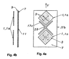
- Figur 4a :
- ein weiteres Ausführungsbeispiel eines Antennenarrays in Draufsicht; und
- Figur 4b :
- eine entsprechende Seitendarstellung gemäß Pfeilrichtung IVb in Figur 4a.
- Figure 1a:
- a schematic plan view of an antenna array with two radiator modules and a decoupling device according to the invention provided between them in plan view;
- Figure 1b:
- a side view along the arrow direction Ib in Figure 1a;
- Figure 2a:
- a modified embodiment of an antenna array according to the invention with a cross-shaped decoupling device in plan view;
- Figure 2b:
- a side view according to the direction of arrow IIb in Figure 2a;
- Figure 2c:
- a schematic perspective view of the embodiment shown in Figure 2a and Figure 2b;
- Figure 3a:
- an exemplary embodiment modified from FIG. 2a, in which so-called patch radiators are used as radiator modules;
- Figure 3b:
- a side view of Figure 3a in the direction of arrow IIIb in Figure 3a;
- Figure 4a:
- a further embodiment of an antenna array in plan view; and
- Figure 4b:
- a corresponding page representation according to arrow direction IVb in Figure 4a.
Nachfolgend wird zunächst auf das Ausführungsbeispiel
gemäß den Figuren 1a und 1b eingegangen. In diesem Ausführungsbeispiel
ist ein Antennenarray mit zwei Strahlermodulen
1 gezeigt, welche aus einer Doppel-Dipol-Anordnung
3 bestehen. Es kann sich dabei beispielsweise um
einen sog. Kreuzdipol handeln, welcher zwei räumlich um
90° versetzt ausgerichtete Systeme umfasst, welche getrennt
gespeist werden. Abweichend dazu können aber auch
andere Doppel-Dipol-Anordnungen eingesetzt werden, bei
denen die einzelnen Dipole in Draufsicht, also in Vorzugsabstrahlrichtung,
beispielsweise eine quadratische Struktur
aufweisen (also ein sog. Dipolquadrat). Schließlich
können auch noch weiter abweichende Strahlermodule zum
Empfang von elektromagnetischen Wellen mit zwei linearen
orthogonalen Polarisationen verwendet werden, wie sie
nachfolgend noch anhand von sog. Patchstrahlern erläutert
werden.The first is the embodiment
received according to Figures 1a and 1b. In this embodiment
is an antenna array with two
Die Strahlermodule 1 sind vor einem Reflektor 7 mit ihren
Dipolen im Abstand zum Reflektor 7 auf diesem sitzend
montiert. Im gezeigten Ausführungsbeispiel wird der Reflektor
7 durch eine Metallisierung 9 auf einer Platine 11
gebildet, auf deren Rückseite sich ein Speisenetzwerk 13
befindet, welches die einzelnen Strahlermodule getrennt
für die jeweilige Polarisation zusammenschaltet. Die Dipole
3 werden dabei über eine sog. Symmetrierung 14 gegenüber
der Platine 11 mechanisch gehalten und elektrisch
kontaktiert, d. h. also von der Platine 13 aus gespeist.The
Im gezeigten Ausführungsbeispiel sind die beiden gezeigten
Strahlermodule 1 in vertikaler Ausrichtung V übereinander
und dabei wiederum in paralleler Ausrichtung zur Reflektorebene
angeordnet. Die Doppel-Dipolanordnung 3 ist so
gewählt, dass mit den Strahlermodulen 1 eine lineare Polarisation
von +45° und -45°, bezogen auf die Vertikale V,
empfangen werden kann.In the exemplary embodiment shown, the two are shown
Zur Erzielung einer hohen Entkopplung zwischen den beiden
Strahlermodulen 1 ist im erläuterten Ausführungsbeispiel
gemäß Figur 1a und 1b ferner eine Entkopplungsstruktur 17
vorgesehen, welche aus einem leitenden Stab 17a besteht.
Dieser ist im gezeigten Ausführungsbeispiel mittig zwischen
den beiden Strahlermodulen 1 angeordnet, wobei sich
der Stab 17a in Verbindungs- oder Anbaurichtung 21 der
Strahlermodule 1, also auf der direkten Verbindungslinie
zwischen den benachbarten Strahlermodulen 1 befindet.To achieve a high level of decoupling between the two
Die Längs- oder Erstreckungskomponente der Entkopplungsstruktur
17, die nachfolgend teilweise auch als Entkopplungs-Strukturelement
17 bezeichnet wird, ist gemäß dem
Ausführungsbeispiel nach Figur 1a bzw. 1b größer als zumindest
1/4 des Abstandes zwischen den beiden benachbarten
Zentren oder Fußpunkten 23 der Strahlermodule oder entspricht
1/4 dieses Abstandes. Die Längskomponente beträgt
dabei vorzugsweise mehr als 40 oder 50 % des erwähnten
Strahlermodul-Abstandes 25.The longitudinal or extension component of the
Der gezeigte Stab 17a ist in geringem Abstand oberhalb der
Reflektorfläche 7 angeordnet und wird dabei über ein Abstandselement
18 auf dem Reflektor 7, d.h. mechanisch
durch die Platine 11 gehalten und dabei mit dem Reflektor
7 elektrisch kontaktiert. Schließlich könnte die Entkopplungsstruktur
aber auch weiter als die Doppel-Dipol-Anordnung
3 von der Reflektorfläche 7 entfernt sein, wobei
jedoch dann Einflüsse auf das Strahlungsdiagramm bei an
sich gleichguter Entkopplung dann festzustellen sind, wenn
der Abstand der Entkopplungsstruktur 17 von der Reflektorfläche
mehr als halb so weit entfernt ist wie die Dipole
der Doppel-Dipol-Anordnung 3. Bevorzugt ist die Anordnung
derart, dass die leitende Entkopplungsstruktur 17 in Form
des Stabes 17a nicht weiter als 1/8 bis 1/4 Wellenlänge
von der Reflektorebene entfernt ist.The
Im praktischen Aufbau kann die Anordnung derart sein, dass
die Dipole 3' beispielsweise im Abstand von 0,1 bis 0,5
Wellenlängen, vorzugsweise 0,2 bis 0,3 Wellenlängen, insbesondere
um 0,25 Wellenlängen, vor der Reflektorfläche
sitzen, wobei die Entkopplungsstruktur in Form des Entkopplungs-Strukturelementes
17a einen Abstand von 0,015
bis 0,125 Wellenlängen, insbesondere 0,015 bis 0,035 Wellenlängen
(also ca. 1/60 bis 1/8, insbesondere 1/60 bis
1/30 der Wellenlänge), gegenüber der Reflektorfläche 7
aufweisen kann.In practice, the arrangement can be such that
the dipoles 3 'for example at a distance of 0.1 to 0.5
Wavelengths, preferably 0.2 to 0.3 wavelengths, in particular
by 0.25 wavelengths, in front of the reflector surface
sit, the decoupling structure in the form of the
Schließlich kann abweichend vom gezeigten Ausführungsbeispiel
die Entkopplungsstruktur 17 nicht in Form eines
Stabes, sondern in Form eines in Draufsicht auf Figur 1a
deckungsgleich zu dem dort gezeigten Stab in der Reflektorfläche
7 eingebrachten Schlitzes bestehen. Möglich ist
auch eine Anordnung mit einer leitenden Fläche im Abstand
vor der Reflektorfläche, in der dann eine entsprechende
Ausnehmung eingebracht ist, die eine Struktur mit Längserstreckung,
vorzugsweise parallel und im Bereich der Verbindungs-
oder Anbaurichtung 21 liegend aufweist.Finally, different from the embodiment shown
the
Das Ausführungsbeispiel gemäß Figur 2a, 2b und 2c unterscheidet
sich von dem vorstehend erläuterten Ausführungsbeispiel
dadurch, dass für die Entkopplungsstruktur 17
kein sich in Verbindungsrichtung 21 erstreckender Stab
17a, sondern ein kreuzförmiges Entkopplungs-Strukturelement
17b aus zwei sich kreuzenden Stäben verwendet wird.
Dabei ist in Figur 2c eine schematische Perspektivdarstellung
des Ausführungsbeispieles nach Figur 2a und 2b wiedergegeben.
Die Stäbe 27 stehen in diesem Ausführungsbeispiel
nahezu senkrecht aufeinander, wobei die beiden Stäbe
jeweils nahezu parallel zu den Polarisationsebenen, d.h.
zu den Dipolen 3', ausgerichtet sind. Das kreuzförmige
Entkopplungs-Strukturelement 17b mit den Stäben 27 ist
ebenfalls wieder leitend, wobei die beiden Stäbe 27 in
ihrem Schnittpunkt 29 leitend miteinander verbunden sind.The exemplary embodiment according to FIGS. 2a, 2b and 2c differs
differs from the exemplary embodiment explained above
in that for the
Die Längskomponente in Verbindungs- oder Anbaurichtung 21
der so geformten kreuzförmigen Entkopplungsstruktur 17 beträgt
dabei beispielsweise 0,25 bis 1 Wellenlänge, vorzugsweise
0,5 bis 0,8 Wellenlängen, insbesondere um 0,7
Wellenlängen. Unter "Längskomponente" ist dabei die Projektion
auf die Vertikale, also auf die direkte Verbindungslinie
zwischen zwei benachbarten Strahlermodulen in
Anbaurichtung zu verstehen. Aufgrund des symmetrischen
Aufbaus ist die Erstreckung in Querrichtung zur Anbaurichtung
21 gleichlang, was aber nicht zwingend sein muss.The longitudinal component in the connection or mounting
Bei dem Ausführungsbeispiel gemäß Figuren 3a und 3b werden abweichend zu dem Ausführungsbeispiel nach Figuren 2a und 2b als Strahlermodule sog. Patchstrahler 1a verwendet, wie sie grundsätzlich aus der Vorveröffentlichung ITG-Fachbericht 128 "Antennen" (Vorträge der ITG-Fachtagung vom 12. bis 15. April 1994 in Dresden), VDE-Verlag GmbH, Berlin, Offenbach, Seiten 259 bis 264 bekannt sind. Es handelt sich dabei um sog. aperturgekoppelte Microstrip-Patch-Antennen mit einer Kreuzschlitz- oder Offset-Schlitz-Anordnung zum Empfang zweier orthogonaler linearer Polarisationen.In the exemplary embodiment according to FIGS. 3a and 3b deviating from the exemplary embodiment according to FIGS. 2a and 2b used as emitter modules. Patch emitters 1a, such as basically from the ITG technical report pre-publication 128 "antennas" (lectures of the ITG conference from April 12 to 15, 1994 in Dresden), VDE-Verlag GmbH, Berlin, Offenbach, pages 259 to 264 are known. It deals are aperture-coupled microstrip patch antennas with a cross slot or offset slot arrangement to receive two orthogonal linear Polarizations.
Die Patchstrahler 1a weisen in Draufsicht quadratische Struktur auf und sind mit ihrer Schlitzanordnung jeweils wieder im 45° Winkel zur Vertikalen V ausgerichtet, um sowohl + 45° als auch -45° Polarisationen empfangen oder senden zu können.The patch radiators 1a have square shapes in plan view Structure on and are with their slot arrangement each again aligned at a 45 ° angle to the vertical V in order to both + 45 ° and -45 ° polarizations received or to be able to send.
Da aufgrund der quadratischen Struktur dieses Einzelspeise-Systems
1 der effektive Abstand zwischen den Außenkonturen
zwischen den beiden Strahlermodulen 1 in Anbaurichtung
21 vergleichsweise kurz bemessen ist, eignet sich
insbesondere eine kreuzförmige Entkopplungsstruktur 17,
wie sie anhand des Ausführungsbeispieles nach Figuren 2a
und 2b beschrieben wurde.Because of the square structure of this single-
Das Ausführungsbeispiel gemäß den Figuren 4a und 4b unterscheidet
sich von demjenigen nach den Figuren 3a und 3b
nur dadurch, dass anstelle des in Form von sich kreuzenden
Stäben 27 gebildeten und vor der Ebene des Reflektors 7
angeordneten kreuzförmigen Entkopplungs-Strukturelemente
17b nunmehr ein entsprechender kreuzförmiger Schlitz 17c
als Entkopplungsstruktur verwendet wird, dessen Anordnung
und Ausrichtung ansonsten der kreuzförmigen Stabanordnung
17b gemäß Figuren 3a und 3b entsprechen kann. Die Dimensionierung
kann dabei ähnlich wie bei der kreuzförmigen
Stabanordnung gemäß Figuren 3a und 3b sein.The exemplary embodiment according to FIGS. 4a and 4b differs
differs from that according to FIGS. 3a and 3b
only in that instead of in the form of intersecting
In den Zeichnungen ist lediglich in den Figuren 1a bis 2c
die mechanische Verankerung und Abstützung der Dipole 3
auf dem Reflektor bzw. der Platine angedeutet worden. Es
werden dazu die üblichen Konstruktionen verwendet, um
beispielsweise über die erwähnten Symmetrierungen 14 die
einzelnen Dipole an einem Substrat oder einer Platine zu
verankern und hierüber elektrisch zu speisen. Werden die
Dipole beispielsweise über zwei Stege oder Arme am Reflektorblech
verankert und darüber gehalten und stehen mit dem
Reflektorblech leitend in Verbindung, so erfolgt die Einspeisung
der Dipole von der Platine aus über separate
Leitungen. Unter anderem auch hierzu wird nur beispielhaft
auf die DE 43 02 905 C2 oder weitere daraus vorbekannte
Dipoleinrichtungen verwiesen. In den weiteren Figuren 3a
folgende ist die mechanische Abstützung der Dipole gegenüber
dem Reflektor bzw. der Platine nicht näher dargestellt.In the drawings is only in Figures 1a to 2c
the mechanical anchoring and support of the
Claims (17)
- Antenna array for simultaneous reception and for simultaneous transmission of electromagnetic waves having two linear, orthogonal polarizations, in particular using a reflector (7), having the following featurescharacterized by the following further featureshaving at least two radiating element modules (1), the alignment of the antenna array is governed by the connection direction (21), in which the radiating element modules (1) are arranged alongside one another and/or one above the other,the radiating element modules (1) having a radiating element arrangement (3) for simultaneous reception or transmission of electromagnetic waves having two orthogonal polarizations,the connection direction (21) of the antenna array is rotated with respect to the alignment of the two mutually orthogonal polarization planes of the two linear orthogonal polarizations to be received or to be transmitted,having a decoupling device (17) between two adjacent radiating element modules (1),the decoupling device (17) comprises a decoupling structure (17) which extends with its longitudinal component parallel to the connection direction (21) of two adjacent radiating element modules (21), andthe longitudinal component of the respective decoupling structure (17) having a length which is greater than or equal to 25% of the radiating element module separation (25) between the centres or bases (23) of the corresponding adjacent radiating element modules (1).
- Antenna array according to Claim 1, characterized in that the longitudinal extent of the longitudinal component of the decoupling structure (17) in the connection direction (21) is at least 50% of the radiating element module separation (25).
- Antenna array according to Claim 1 or 2, characterized in that the ratio of the longitudinal component of the decoupling structure (17) measured in its connection direction (21) to its extent in the direction of its transverse component is greater than 0.5 or is 0.5.
- Antenna array according to Claim 3, characterized in that the ratio of the longitudinal extent in the connection direction (21) to the transverse extent, running at right angles to this, of the decoupling structure (17) is greater than or equal to 0.7 and less than or equal to 1.5, preferably greater than or equal to 0.9 and less than or equal to 1.1, in particular about 1.0.
- Antenna array according to Claim 1 or 2, characterized in that the decoupling structure (17) is at least one electrically conductive rod (17a) extending with its longitudinal component in the connection direction (21), or a longitudinal element extending essentially in the connection direction (21).
- Antenna array according to one of Claims 1 to 5, characterized in that the decoupling structure (17) comprises at least one slot (17c) which extends with its longitudinal component in the connection direction (21), and is formed in the reflector (7) or in a separate conductive surface arranged at a distance in front of the reflector.
- Antenna array according to one of Claims 1 to 6, characterized in that the decoupling structure (17, 17a) is aligned at least virtually parallel to the direct connecting line between two adjacent radiating element modules (1) and, at the same time, preferably extends on the direct connecting line between two adjacent decoupling structures (17, 17a).
- Antenna array according to one of Claims 1 to 7, characterized in that the decoupling structure (17) comprises a cruciform arrangement (17b, 17c, 17d).
- Antenna array according to Claim 8, characterized in that the decoupling structure (17) comprises two, or a multiple thereof, rods (27) which are arranged at least approximately at right angles to one another, are conductive and are aligned with their respective longitudinal extent parallel to the two polarizations which are aligned orthogonally with respect to one another.
- Antenna array according to Claim 9, characterized in that the decoupling structure (17) in the form of a cruciform arrangement (17b) comprises rods (27b) which are arranged in a cruciform manner with respect to one another and parallel to the reflector plane (7) and are conductively connected at their intersection (29).
- Antenna array according to Claim 8, characterized in that the cruciform arrangement comprises a cruciform slot arrangement (17c) which is formed in the reflector (7) or in a conductive surface arranged in front of the reflector (7).
- Antenna array according to one of Claims 1 to 11, characterized in that the decoupling structure (17) is formed on different separation planes with respect to the reflector (7), the distance from the reflector plane being less than or equal to half a wavelength of the electromagentic waves to be received or to be transmitted.
- Antenna array according to one of Claims 1 to 12, characterized in that the decoupling structure (17) is formed symmetrically with respect to the direct connecting line between two adjacent radiating element modules (1) and thus symmetrically with respect to the connection direction (21).
- Antenna array according to one of Claims 1 to 13, characterized in that the decoupling structure (17) is formed symmetrically with respect to a centre transverse plane at right angles to the direct connecting line between two adjacent radiating element modules (1).
- Antenna array according to one of Claims 8 to 14, characterized in that the two mutually perpendicular components of the cruciform arrangement (17b, 17c, 17d) of the decoupling structure (17) are aligned parallel to the two mutually orthogonal polarization planes of the two linear orthogonal polarizations to be received or to be transmitted.
- Antenna array according to one of Claims 1 to 15, characterized in that the radiating element arrangement (3) comprises a dipole radiating element arrangement.
- Antenna array according to one of Claims 1 to 15, characterized in that the radiating element arrangement (3) comprises a patch radiating element arrangement (1a).
Applications Claiming Priority (3)
| Application Number | Priority Date | Filing Date | Title |
|---|---|---|---|
| DE19627015 | 1996-07-04 | ||
| DE19627015A DE19627015C2 (en) | 1996-07-04 | 1996-07-04 | Antenna field |
| PCT/EP1997/002922 WO1998001923A1 (en) | 1996-07-04 | 1997-06-05 | Antenna array |
Publications (2)
| Publication Number | Publication Date |
|---|---|
| EP0848862A1 EP0848862A1 (en) | 1998-06-24 |
| EP0848862B1 true EP0848862B1 (en) | 2002-04-17 |
Family
ID=7798955
Family Applications (1)
| Application Number | Title | Priority Date | Filing Date |
|---|---|---|---|
| EP97927140A Expired - Lifetime EP0848862B1 (en) | 1996-07-04 | 1997-06-05 | Antenna array |
Country Status (7)
| Country | Link |
|---|---|
| US (1) | US6025812A (en) |
| EP (1) | EP0848862B1 (en) |
| KR (1) | KR100454146B1 (en) |
| CA (1) | CA2228548C (en) |
| DE (2) | DE19627015C2 (en) |
| ES (1) | ES2175417T3 (en) |
| WO (1) | WO1998001923A1 (en) |
Cited By (1)
| Publication number | Priority date | Publication date | Assignee | Title |
|---|---|---|---|---|
| WO2022051906A1 (en) * | 2020-09-08 | 2022-03-17 | 摩比天线技术(深圳)有限公司 | Decoupling element and antenna |
Families Citing this family (84)
| Publication number | Priority date | Publication date | Assignee | Title |
|---|---|---|---|---|
| US5952983A (en) * | 1997-05-14 | 1999-09-14 | Andrew Corporation | High isolation dual polarized antenna system using dipole radiating elements |
| DE19823750A1 (en) * | 1998-05-27 | 1999-12-09 | Kathrein Werke Kg | Antenna array with several primary radiator modules arranged vertically one above the other |
| DE19823749C2 (en) * | 1998-05-27 | 2002-07-11 | Kathrein Werke Kg | Dual polarized multi-range antenna |
| DE19860121A1 (en) | 1998-12-23 | 2000-07-13 | Kathrein Werke Kg | Dual polarized dipole emitter |
| US6615026B1 (en) * | 1999-02-01 | 2003-09-02 | A. W. Technologies, Llc | Portable telephone with directional transmission antenna |
| FI990395A (en) | 1999-02-24 | 2000-08-25 | Nokia Networks Oy | Hardware for attenuating interference between antennas |
| US6512475B1 (en) * | 1999-04-02 | 2003-01-28 | Geophysical Survey Systems, Inc. | High-frequency dual-channel ground-penetrating impulse antenna and method of using same for identifying plastic pipes and rebar in concrete |
| DE19931907C2 (en) | 1999-07-08 | 2001-08-09 | Kathrein Werke Kg | antenna |
| CN1196231C (en) * | 1999-10-26 | 2005-04-06 | 弗拉克托斯股份有限公司 | Interlaced multiband antenna arrays |
| US6356242B1 (en) * | 2000-01-27 | 2002-03-12 | George Ploussios | Crossed bent monopole doublets |
| DE10012809A1 (en) | 2000-03-16 | 2001-09-27 | Kathrein Werke Kg | Dual polarized dipole array antenna has supply cable fed to supply point on one of two opposing parallel dipoles, connecting cable to supply point on opposing dipole |
| US6774745B2 (en) * | 2000-04-27 | 2004-08-10 | Bae Systems Information And Electronic Systems Integration Inc | Activation layer controlled variable impedance transmission line |
| AU2001257500A1 (en) * | 2000-05-02 | 2001-11-12 | Bae Systems Information And Electronic Systems Integration, Inc. | Low profile, broadband, dual mode, modified notch antenna |
| US6452549B1 (en) | 2000-05-02 | 2002-09-17 | Bae Systems Information And Electronic Systems Integration Inc | Stacked, multi-band look-through antenna |
| US6690331B2 (en) | 2000-05-24 | 2004-02-10 | Bae Systems Information And Electronic Systems Integration Inc | Beamforming quad meanderline loaded antenna |
| US6323814B1 (en) | 2000-05-24 | 2001-11-27 | Bae Systems Information And Electronic Systems Integration Inc | Wideband meander line loaded antenna |
| US6359599B2 (en) | 2000-05-31 | 2002-03-19 | Bae Systems Information And Electronic Systems Integration Inc | Scanning, circularly polarized varied impedance transmission line antenna |
| AU2001265221A1 (en) | 2000-05-31 | 2001-12-11 | Bae Systems Information And Electronic Systems Integration, Inc. | Wideband meander line loaded antenna |
| US6384792B2 (en) | 2000-06-14 | 2002-05-07 | Bae Systemsinformation Electronic Systems Integration, Inc. | Narrowband/wideband dual mode antenna |
| US6300915B1 (en) * | 2000-11-09 | 2001-10-09 | Bae Systems Aerospace Inc. Advanced Systems | Vertical array antennas for differential GPS ground stations |
| DE10064129B4 (en) * | 2000-12-21 | 2006-04-20 | Kathrein-Werke Kg | Antenna, in particular mobile radio antenna |
| KR100403764B1 (en) * | 2000-12-28 | 2003-10-30 | 주식회사 하이닉스반도체 | Polarization Diversity Applicable Smart Antenna |
| FR2823017B1 (en) * | 2001-03-29 | 2005-05-20 | Cit Alcatel | MULTIBAND TELECOMMUNICATIONS ANTENNA |
| CN1507673A (en) * | 2001-04-16 | 2004-06-23 | �����ɷ� | Dual-band dual-polarized antenna array |
| DE10150150B4 (en) | 2001-10-11 | 2006-10-05 | Kathrein-Werke Kg | Dual polarized antenna array |
| DE10203873A1 (en) * | 2002-01-31 | 2003-08-14 | Kathrein Werke Kg | Dual polarized radiator arrangement |
| EP1509969A4 (en) * | 2002-03-26 | 2005-08-31 | Andrew Corp | Multiband dual polarized adjustable beamtilt base station antenna |
| US6674406B1 (en) * | 2002-10-08 | 2004-01-06 | The United States Of America As Represented By The Secretary Of The Navy | Microstrip patch antenna with progressive slot loading |
| DE10316564B4 (en) | 2003-04-10 | 2006-03-09 | Kathrein-Werke Kg | Antenna with at least one dipole or a dipole-like radiator arrangement |
| US6940465B2 (en) | 2003-05-08 | 2005-09-06 | Kathrein-Werke Kg | Dual-polarized dipole antenna element |
| US7132995B2 (en) | 2003-12-18 | 2006-11-07 | Kathrein-Werke Kg | Antenna having at least one dipole or an antenna element arrangement similar to a dipole |
| DE10359623A1 (en) * | 2003-12-18 | 2005-07-21 | Kathrein-Werke Kg | Mobile antenna arrangement for a base station |
| US7027004B2 (en) | 2003-12-18 | 2006-04-11 | Kathrein-Werke Kg | Omnidirectional broadband antenna |
| US7015871B2 (en) | 2003-12-18 | 2006-03-21 | Kathrein-Werke Kg | Mobile radio antenna arrangement for a base station |
| DE10359622A1 (en) * | 2003-12-18 | 2005-07-21 | Kathrein-Werke Kg | Antenna with at least one dipole or a dipole-like radiator arrangement |
| JP4169709B2 (en) * | 2004-02-16 | 2008-10-22 | 株式会社国際電気通信基礎技術研究所 | Array antenna device |
| DE602004012705T2 (en) * | 2004-02-20 | 2008-07-17 | Alcatel Lucent | Dual polarized antenna module |
| DE102004025904B4 (en) * | 2004-05-27 | 2007-04-05 | Kathrein-Werke Kg | antenna |
| US7868843B2 (en) * | 2004-08-31 | 2011-01-11 | Fractus, S.A. | Slim multi-band antenna array for cellular base stations |
| US7148848B2 (en) * | 2004-10-27 | 2006-12-12 | General Motors Corporation | Dual band, bent monopole antenna |
| DE102005005781A1 (en) * | 2005-02-08 | 2006-08-10 | Kathrein-Werke Kg | Radom, in particular for mobile radio antennas and associated mobile radio antenna |
| KR100725501B1 (en) * | 2005-08-19 | 2007-06-08 | 삼성전자주식회사 | Electromagnetic Wave Measuring Apparatus |
| US7616168B2 (en) * | 2005-08-26 | 2009-11-10 | Andrew Llc | Method and system for increasing the isolation characteristic of a crossed dipole pair dual polarized antenna |
| US7358924B2 (en) | 2005-10-07 | 2008-04-15 | Kathrein-Werke Kg | Feed network, and/or antenna having at least one antenna element and a feed network |
| WO2007042938A2 (en) | 2005-10-14 | 2007-04-19 | Fractus, Sa | Slim triple band antenna array for cellular base stations |
| DE102006037518B3 (en) | 2006-08-10 | 2008-03-06 | Kathrein-Werke Kg | Antenna arrangement, in particular for a mobile radio base station |
| DE102006037517A1 (en) | 2006-08-10 | 2008-02-21 | Kathrein-Werke Kg | Antenna arrangement, in particular for a mobile radio base station |
| DE102006039279B4 (en) | 2006-08-22 | 2013-10-10 | Kathrein-Werke Kg | Dipole radiator arrangement |
| DE102007006559B3 (en) * | 2007-02-09 | 2008-09-11 | Kathrein-Werke Kg | Mobile antenna, in particular for a base station |
| WO2008148569A2 (en) * | 2007-06-06 | 2008-12-11 | Fractus, S.A. | Dual-polarized radiating element, dual-band dual-polarized antenna assembly and dual-polarized antenna array |
| JP5294443B2 (en) * | 2007-06-21 | 2013-09-18 | 三星電子株式会社 | Antenna device and wireless communication terminal |
| WO2010033004A2 (en) * | 2008-09-22 | 2010-03-25 | 주식회사 케이엠더블유 | Dual-frequency / polarization antenna for mobile-communications base station |
| DE102008059268A1 (en) | 2008-11-27 | 2009-11-19 | Kathrein-Werke Kg | Positional recognition device for antenna, particularly mobile phone antenna, has integrated inclination sensor and global positioning system, where device is provided in control unit for adjusting electrical beam deflection with antenna |
| US8838176B2 (en) * | 2012-01-10 | 2014-09-16 | Mediatek Inc. | High gain antenna and wireless device using the same |
| TWI497832B (en) * | 2012-06-18 | 2015-08-21 | Wistron Neweb Corp | Decoupling circuit and antenna device |
| US9437935B2 (en) | 2013-02-27 | 2016-09-06 | Microsoft Technology Licensing, Llc | Dual band antenna pair with high isolation |
| CN103715519B (en) * | 2013-06-09 | 2016-12-28 | 京信通信技术(广州)有限公司 | Double polarization array antenna and radiating element thereof |
| DE102013012305A1 (en) | 2013-07-24 | 2015-01-29 | Kathrein-Werke Kg | Wideband antenna array |
| KR101636828B1 (en) * | 2015-01-08 | 2016-07-08 | 인하대학교 산학협력단 | 4-port MIMO antenna for LTE femtocell using cross decoupler |
| JP6610652B2 (en) | 2015-02-16 | 2019-11-27 | 日本電気株式会社 | Multiband antenna, multiband antenna array, and wireless communication apparatus |
| DE102015002441A1 (en) | 2015-02-26 | 2016-09-01 | Kathrein-Werke Kg | Radome and associated mobile radio antenna and method for the production of the radome or the mobile radio antenna |
| US9799953B2 (en) | 2015-03-26 | 2017-10-24 | Microsoft Technology Licensing, Llc | Antenna isolation |
| DE102015007504B4 (en) | 2015-06-11 | 2019-03-28 | Kathrein Se | Dipole radiator arrangement |
| DE102015007503A1 (en) | 2015-06-11 | 2016-12-15 | Kathrein-Werke Kg | Dipole radiator arrangement |
| DE102015115892A1 (en) | 2015-09-21 | 2017-03-23 | Kathrein-Werke Kg | Dipolsockel |
| CN108028462B (en) * | 2015-11-25 | 2021-11-05 | 康普技术有限责任公司 | Phased array antenna with decoupling unit |
| DE102016104610A1 (en) | 2016-03-14 | 2017-09-14 | Kathrein-Werke Kg | Multiple holder for a dipole radiator arrangement and a dipole radiator arrangement with such a multiple holder |
| US10148015B2 (en) | 2016-03-14 | 2018-12-04 | Kathrein-Werke Kg | Dipole-shaped antenna element arrangement |
| DE102016104611B4 (en) | 2016-03-14 | 2020-07-09 | Telefonaktiebolaget Lm Ericsson (Publ) | Dipole-shaped radiator arrangement |
| DE102016112257A1 (en) | 2016-07-05 | 2018-01-11 | Kathrein-Werke Kg | Antenna arrangement with at least one dipole radiator arrangement |
| DE102016219163A1 (en) | 2016-10-04 | 2018-04-05 | Bayerische Motoren Werke Aktiengesellschaft | Antenna arrangement for a vehicle and vehicle |
| CN110462931B (en) * | 2017-03-29 | 2021-07-06 | 日本电业工作株式会社 | Array antenna and sector antenna |
| EP4246726A3 (en) | 2017-05-16 | 2023-11-22 | Huawei Technologies Co., Ltd. | Antenna |
| DE102017116920A1 (en) | 2017-06-09 | 2018-12-13 | Kathrein Se | Dual polarized cross dipole and antenna arrangement with two such dual polarized cross dipoles |
| CN107546489B (en) * | 2017-08-16 | 2020-12-15 | 京信通信技术(广州)有限公司 | Multi-frequency base station antenna for eliminating coupling resonance |
| CN111384595B (en) * | 2018-12-29 | 2021-07-16 | 华为技术有限公司 | MIMO antenna and base station |
| WO2020190863A1 (en) | 2019-03-21 | 2020-09-24 | Commscope Technologies Llc | Base station antennas having parasitic assemblies for improving cross-polarization discrimination performance |
| DE102019108901A1 (en) | 2019-03-22 | 2020-09-24 | Telefonaktiebolaget Lm Ericsson (Publ) | Antenna arrangement for mobile radio systems with at least one dual-polarized crossed dipole |
| CN110176671A (en) * | 2019-05-20 | 2019-08-27 | 深圳市信维通信股份有限公司 | A kind of millimeter wave array antenna |
| CN115986429A (en) | 2020-03-24 | 2023-04-18 | 康普技术有限责任公司 | Base station antenna with active antenna module and related apparatus and methods |
| DE202021106120U1 (en) | 2020-03-24 | 2021-12-14 | Commscope Technologies Llc | Radiating elements with angled feed shafts and base station antennas including the same |
| WO2021222217A1 (en) * | 2020-04-28 | 2021-11-04 | Commscope Technologies Llc | Base station antennas having reflector assemblies including a nonmetallic substrate having a metallic layer thereon |
| CN213753057U (en) * | 2020-12-31 | 2021-07-20 | 罗森伯格技术有限公司 | Antenna element and antenna |
| EP4040602A1 (en) * | 2021-02-08 | 2022-08-10 | Nokia Technologies Oy | An array of patch antennas |
Family Cites Families (7)
| Publication number | Priority date | Publication date | Assignee | Title |
|---|---|---|---|---|
| US3510876A (en) * | 1967-06-29 | 1970-05-05 | Itt | Vertical beam steering antenna system |
| US3541559A (en) * | 1968-04-10 | 1970-11-17 | Westinghouse Electric Corp | Antenna for producing circular polarization over wide angles |
| DE7142601U (en) * | 1971-11-11 | 1972-07-13 | Rohde & Schwarz | DIRECTIONAL BEAM FOR CIRCULAR OR ELLIPTICAL POLARIZATION FOR CONSTRUCTION OF ROUND BEAM ANTENNAS |
| GB2265258B (en) * | 1992-03-11 | 1995-09-27 | Siemens Plessey Electronic | Antenna array incorporating a choke |
| DE4302905C1 (en) * | 1993-02-02 | 1994-03-17 | Kathrein Werke Kg | Directional antenna, pref. symmetrical dipole type - is formed by cutting and/or stamping out sections of reflector wall and bending remaining bridging piece |
| GB9410994D0 (en) * | 1994-06-01 | 1994-07-20 | Alan Dick & Company Limited | Antennae |
| SE9404312L (en) * | 1994-12-12 | 1996-04-01 | Teracom Components Ab | Device for antenna systems for breaking high frequency electric currents in the supporting structure |
-
1996
- 1996-07-04 DE DE19627015A patent/DE19627015C2/en not_active Expired - Fee Related
-
1997
- 1997-06-05 EP EP97927140A patent/EP0848862B1/en not_active Expired - Lifetime
- 1997-06-05 DE DE59707037T patent/DE59707037D1/en not_active Expired - Lifetime
- 1997-06-05 WO PCT/EP1997/002922 patent/WO1998001923A1/en active IP Right Grant
- 1997-06-05 KR KR10-1998-0701162A patent/KR100454146B1/en not_active IP Right Cessation
- 1997-06-05 ES ES97927140T patent/ES2175417T3/en not_active Expired - Lifetime
- 1997-06-05 CA CA002228548A patent/CA2228548C/en not_active Expired - Fee Related
- 1997-06-05 US US09/029,198 patent/US6025812A/en not_active Expired - Lifetime
Cited By (1)
| Publication number | Priority date | Publication date | Assignee | Title |
|---|---|---|---|---|
| WO2022051906A1 (en) * | 2020-09-08 | 2022-03-17 | 摩比天线技术(深圳)有限公司 | Decoupling element and antenna |
Also Published As
| Publication number | Publication date |
|---|---|
| KR100454146B1 (en) | 2005-01-24 |
| WO1998001923A1 (en) | 1998-01-15 |
| US6025812A (en) | 2000-02-15 |
| DE19627015A1 (en) | 1998-01-08 |
| CA2228548C (en) | 2003-01-14 |
| CA2228548A1 (en) | 1998-01-15 |
| ES2175417T3 (en) | 2002-11-16 |
| KR19990037683A (en) | 1999-05-25 |
| DE59707037D1 (en) | 2002-05-23 |
| EP0848862A1 (en) | 1998-06-24 |
| DE19627015C2 (en) | 2000-07-13 |
Similar Documents
| Publication | Publication Date | Title |
|---|---|---|
| EP0848862B1 (en) | Antenna array | |
| EP1082782B1 (en) | Dual polarised multi-range antenna | |
| EP1749331B1 (en) | Mobile radio antenna with beam-forming element | |
| EP1082781B1 (en) | Antenna array with several vertically superposed primary radiator modules | |
| EP1194982B1 (en) | Antenna | |
| DE10256960B3 (en) | Two-dimensional antenna array | |
| EP1470615B1 (en) | Dual-polarized radiating assembly | |
| EP1057224B1 (en) | Dual-polarized dipole antenna | |
| DE69834102T2 (en) | WORKING ANTENNA ON TWO ISOLATED CHANNELS | |
| EP2929589B1 (en) | Dual polarized, omnidirectional antenna | |
| DE69829037T2 (en) | ANTENNA WITH IMPROVED CHANNEL SEPARATION | |
| DE69832592T2 (en) | DEVICE FOR RECEIVING AND SENDING RADIO SIGNALS | |
| DE10012809A1 (en) | Dual polarized dipole array antenna has supply cable fed to supply point on one of two opposing parallel dipoles, connecting cable to supply point on opposing dipole | |
| DE69938063T2 (en) | IMPROVING POLARIZATION SEPARATION | |
| DE69828848T2 (en) | Directional antenna system with crossed polarization | |
| DE69835944T2 (en) | ARRANGEMENT WITH ANTENNA UNITS | |
| EP1525642B1 (en) | Two-dimensional antenna array | |
| WO2016050336A1 (en) | Multi-band radiator system | |
| DE602004012705T2 (en) | Dual polarized antenna module | |
| DE19815003A1 (en) | Dual polarized antenna element | |
| EP2514027B1 (en) | Dual-polarised antenna array, in particular a mobile radio antenna | |
| DE202004008770U1 (en) | Mobile radio base station antenna element has conducting main reflector, dual polarized radiator and cross shaped passive subreflector |
Legal Events
| Date | Code | Title | Description |
|---|---|---|---|
| PUAI | Public reference made under article 153(3) epc to a published international application that has entered the european phase |
Free format text: ORIGINAL CODE: 0009012 |
|
| 17P | Request for examination filed |
Effective date: 19980219 |
|
| AK | Designated contracting states |
Kind code of ref document: A1 Designated state(s): CH DE DK ES FI FR GB IE IT LI SE |
|
| 17Q | First examination report despatched |
Effective date: 20010417 |
|
| GRAG | Despatch of communication of intention to grant |
Free format text: ORIGINAL CODE: EPIDOS AGRA |
|
| REG | Reference to a national code |
Ref country code: GB Ref legal event code: IF02 |
|
| RIC1 | Information provided on ipc code assigned before grant |
Free format text: 7H 01Q 21/24 A |
|
| GRAG | Despatch of communication of intention to grant |
Free format text: ORIGINAL CODE: EPIDOS AGRA |
|
| GRAH | Despatch of communication of intention to grant a patent |
Free format text: ORIGINAL CODE: EPIDOS IGRA |
|
| GRAH | Despatch of communication of intention to grant a patent |
Free format text: ORIGINAL CODE: EPIDOS IGRA |
|
| GRAA | (expected) grant |
Free format text: ORIGINAL CODE: 0009210 |
|
| AK | Designated contracting states |
Kind code of ref document: B1 Designated state(s): CH DE DK ES FI FR GB IE IT LI SE |
|
| RIN1 | Information on inventor provided before grant (corrected) |
Inventor name: KLINGER, GEORG Inventor name: GOETTL, MAX Inventor name: GABRIEL, ROLAND |
|
| REG | Reference to a national code |
Ref country code: CH Ref legal event code: EP |
|
| GBT | Gb: translation of ep patent filed (gb section 77(6)(a)/1977) |
Effective date: 20020417 |
|
| REG | Reference to a national code |
Ref country code: IE Ref legal event code: FG4D Free format text: GERMAN |
|
| REF | Corresponds to: |
Ref document number: 59707037 Country of ref document: DE Date of ref document: 20020523 |
|
| REG | Reference to a national code |
Ref country code: CH Ref legal event code: NV Representative=s name: SCHMAUDER & PARTNER AG PATENTANWALTSBUERO |
|
| PG25 | Lapsed in a contracting state [announced via postgrant information from national office to epo] |
Ref country code: DK Free format text: LAPSE BECAUSE OF FAILURE TO SUBMIT A TRANSLATION OF THE DESCRIPTION OR TO PAY THE FEE WITHIN THE PRESCRIBED TIME-LIMIT Effective date: 20020717 |
|
| ET | Fr: translation filed | ||
| REG | Reference to a national code |
Ref country code: ES Ref legal event code: FG2A Ref document number: 2175417 Country of ref document: ES Kind code of ref document: T3 |
|
| PLBE | No opposition filed within time limit |
Free format text: ORIGINAL CODE: 0009261 |
|
| STAA | Information on the status of an ep patent application or granted ep patent |
Free format text: STATUS: NO OPPOSITION FILED WITHIN TIME LIMIT |
|
| 26N | No opposition filed |
Effective date: 20030120 |
|
| PGFP | Annual fee paid to national office [announced via postgrant information from national office to epo] |
Ref country code: FI Payment date: 20050623 Year of fee payment: 9 |
|
| PG25 | Lapsed in a contracting state [announced via postgrant information from national office to epo] |
Ref country code: FI Free format text: LAPSE BECAUSE OF NON-PAYMENT OF DUE FEES Effective date: 20060605 |
|
| REG | Reference to a national code |
Ref country code: CH Ref legal event code: PCAR Free format text: SCHMAUDER & PARTNER AG PATENT- UND MARKENANWAELTE VSP;ZWAENGIWEG 7;8038 ZUERICH (CH) |
|
| PGFP | Annual fee paid to national office [announced via postgrant information from national office to epo] |
Ref country code: IT Payment date: 20100626 Year of fee payment: 14 |
|
| PGFP | Annual fee paid to national office [announced via postgrant information from national office to epo] |
Ref country code: CH Payment date: 20100624 Year of fee payment: 14 |
|
| REG | Reference to a national code |
Ref country code: CH Ref legal event code: PL |
|
| PG25 | Lapsed in a contracting state [announced via postgrant information from national office to epo] |
Ref country code: IT Free format text: LAPSE BECAUSE OF NON-PAYMENT OF DUE FEES Effective date: 20110605 |
|
| PG25 | Lapsed in a contracting state [announced via postgrant information from national office to epo] |
Ref country code: CH Free format text: LAPSE BECAUSE OF NON-PAYMENT OF DUE FEES Effective date: 20110630 Ref country code: LI Free format text: LAPSE BECAUSE OF NON-PAYMENT OF DUE FEES Effective date: 20110630 |
|
| PGFP | Annual fee paid to national office [announced via postgrant information from national office to epo] |
Ref country code: SE Payment date: 20150623 Year of fee payment: 19 |
|
| PGFP | Annual fee paid to national office [announced via postgrant information from national office to epo] |
Ref country code: IE Payment date: 20150622 Year of fee payment: 19 |
|
| REG | Reference to a national code |
Ref country code: FR Ref legal event code: PLFP Year of fee payment: 20 |
|
| PGFP | Annual fee paid to national office [announced via postgrant information from national office to epo] |
Ref country code: DE Payment date: 20160622 Year of fee payment: 20 Ref country code: ES Payment date: 20160622 Year of fee payment: 20 Ref country code: GB Payment date: 20160628 Year of fee payment: 20 |
|
| PGFP | Annual fee paid to national office [announced via postgrant information from national office to epo] |
Ref country code: FR Payment date: 20160621 Year of fee payment: 20 |
|
| REG | Reference to a national code |
Ref country code: SE Ref legal event code: EUG |
|
| PG25 | Lapsed in a contracting state [announced via postgrant information from national office to epo] |
Ref country code: SE Free format text: LAPSE BECAUSE OF NON-PAYMENT OF DUE FEES Effective date: 20160606 |
|
| REG | Reference to a national code |
Ref country code: IE Ref legal event code: MM4A |
|
| PG25 | Lapsed in a contracting state [announced via postgrant information from national office to epo] |
Ref country code: IE Free format text: LAPSE BECAUSE OF NON-PAYMENT OF DUE FEES Effective date: 20160605 |
|
| REG | Reference to a national code |
Ref country code: DE Ref legal event code: R071 Ref document number: 59707037 Country of ref document: DE |
|
| REG | Reference to a national code |
Ref country code: GB Ref legal event code: PE20 Expiry date: 20170604 |
|
| PG25 | Lapsed in a contracting state [announced via postgrant information from national office to epo] |
Ref country code: GB Free format text: LAPSE BECAUSE OF EXPIRATION OF PROTECTION Effective date: 20170604 |
|
| REG | Reference to a national code |
Ref country code: ES Ref legal event code: FD2A Effective date: 20170926 |
|
| PG25 | Lapsed in a contracting state [announced via postgrant information from national office to epo] |
Ref country code: ES Free format text: LAPSE BECAUSE OF EXPIRATION OF PROTECTION Effective date: 20170606 |
|
| REG | Reference to a national code |
Ref country code: DE Ref legal event code: R082 Ref document number: 59707037 Country of ref document: DE Representative=s name: FLACH BAUER STAHL PATENTANWAELTE PARTNERSCHAFT, DE Ref country code: DE Ref legal event code: R081 Ref document number: 59707037 Country of ref document: DE Owner name: KATHREIN SE, DE Free format text: FORMER OWNER: KATHREIN-WERKE KG, 83022 ROSENHEIM, DE |
|
| REG | Reference to a national code |
Ref country code: GB Ref legal event code: 732E Free format text: REGISTERED BETWEEN 20190314 AND 20190320 |