EP1748017A1 - Emergency stop device for elevator - Google Patents
Emergency stop device for elevator Download PDFInfo
- Publication number
- EP1748017A1 EP1748017A1 EP04734136A EP04734136A EP1748017A1 EP 1748017 A1 EP1748017 A1 EP 1748017A1 EP 04734136 A EP04734136 A EP 04734136A EP 04734136 A EP04734136 A EP 04734136A EP 1748017 A1 EP1748017 A1 EP 1748017A1
- Authority
- EP
- European Patent Office
- Prior art keywords
- car
- rail
- contact
- wedge
- rail pinching
- Prior art date
- Legal status (The legal status is an assumption and is not a legal conclusion. Google has not performed a legal analysis and makes no representation as to the accuracy of the status listed.)
- Withdrawn
Links
Images





Classifications
-
- B—PERFORMING OPERATIONS; TRANSPORTING
- B66—HOISTING; LIFTING; HAULING
- B66B—ELEVATORS; ESCALATORS OR MOVING WALKWAYS
- B66B5/00—Applications of checking, fault-correcting, or safety devices in elevators
- B66B5/02—Applications of checking, fault-correcting, or safety devices in elevators responsive to abnormal operating conditions
- B66B5/16—Braking or catch devices operating between cars, cages, or skips and fixed guide elements or surfaces in hoistway or well
- B66B5/18—Braking or catch devices operating between cars, cages, or skips and fixed guide elements or surfaces in hoistway or well and applying frictional retarding forces
- B66B5/22—Braking or catch devices operating between cars, cages, or skips and fixed guide elements or surfaces in hoistway or well and applying frictional retarding forces by means of linearly-movable wedges
Definitions
- the present invention relates to a safety device for an elevator for forcibly stopping an elevator car that is being raised and lowered at an abnormal speed.
- JP 2002-220171 A discloses a safety device with which the wedge is pressed against each of the pair of car guide rails to thereby prevent the car from falling.
- the car is provided with the safety link connecting between the respective wedges.
- the wedges and the safety link are provided below the car.
- Connected to the safety link is the governor rope that moves in synchronism with the raising and lowering of the car.
- the governor rope is wound around the sheave of the governor. Accordingly, clamping of the governor rope by the governor actuates the safety link, causing the wedges to be simultaneously pressed against the respective car guide rails.
- the safety link connecting between the respective wedges is arranged below the car, so the overall vertical length of an elevating body including the car is enlarged downwards, resulting in an increase in pit depth (the length of the gap between the lower end portion of the elevating body and the bottom portion of the hoistway when the car is at rest at the lowest floor).
- pit depth the length of the gap between the lower end portion of the elevating body and the bottom portion of the hoistway when the car is at rest at the lowest floor.
- the present invention has been made to solve the problems as mentioned above, and therefore it is an obj ect of the present invention to provide a safety device for an elevator which enables space saving for an elevator apparatus as a whole.
- a safety device for an elevator, for braking a car guided by a pair of guide rails includes a pair of rail pinching portions each having: a braking member capable of coming into and out of contact with each of the guide rails; and an actuating mechanism for pressing the braking member against each of the guide rails.
- the pair of rail pinching portions are mounted onto the car and brake the car with respect to the guide rails upon actuation of the actuating mechanism.
- the respective actuating mechanisms are actuated independently from each other.
- the respective rail pinching portions are arranged so that the rail pinching portions sandwich the car therebetween with respect to a horizontal direction.
- Fig. 1 is a schematic diagram showing an elevator apparatus according to Embodiment 1 of the present invention.
- a pair of car guide rails 2 are disposed in a hoistway 1.
- a car 3 is raised and lowered in the hoistway 1 while being guided by the car guide rails 2.
- a hoisting machine (not shown) for raising and lowering the car 3 and a counterweight (not shown).
- a main rope 4 is wound around a driving sheave of the hoisting machine.
- the car 3 and the counterweight are suspended in the hoistway 1 by the main rope 4.
- the car 3 is mounted with a pair of rail pinching portions 5 as braking means opposed to the respective car guide rails 2. Braking is applied to the car 3 upon actuation of the rail pinching portions 5.
- a governor 6 serving as car speed detecting means for detecting the raising/lowering speed of the car 3.
- the governor 6 has a governor main body 7, and a governor sheave 8 rotatable with respect to the governor main body 7.
- a rotatable tension pulley 9 is arranged at a lower end portion of the hoistway 1.
- a governor rope 10 connected to the car 3 is looped between the governor sheave 8 and the tension pulley 9. The connecting portion of the governor rope 10 with the car 3 is vertically reciprocated together with the car 3. The governor sheave 8 and the tension pulley 9 are thus rotated at a speed corresponding to the raising/lowering speed of the car 3.
- the governor 6 is adapted to actuate a brake device of the hoisting machine when the raising/lowering speed of the car 3 reaches a preset overspeed. Further, the governor 6 is provided with a switch portion 11 serving as an output portion for outputting an actuating signal to the rail pinching portions 5 when the lowering speed of the car 3 reaches a second overspeed (set overspeed) that is higher than the first overspeed.
- the switch portion 11 has a contact portion 16 that is mechanically opened and closed by means of an overspeed lever displaced according to the centrifugal force of the governor sheave 8 being rotated.
- the contact portion 16 is electrically connected to a battery 12, which is an uninterruptible power supply capable of supplying power even in the event of a power failure, and to a control panel 13 for controlling the operation of an elevator through a power cable 14 and a connecting cable 15, respectively.
- a control cable (traveling cable) is connected between the car 3 and the control panel 13.
- the control cable includes, in addition to a plurality of power lines and signal lines, an emergency stop wiring 17 that is electrically connected between the control panel 13 and each rail pinching portion 5.
- electric power from the battery 12 is supplied to each rail pinching portion 5 by way of the power cable 14, the switching portion 11, the connecting cable 15, a power supply circuit inside the control panel 13, and the emergency stop wiring 17.
- transmitting means includes the connecting cable 15, the power supply circuit inside the control panel 13, and the emergency stop wiring 17.
- Fig. 2 is a front view showing the car 3 shown in Fig. 1
- Fig. 3 is a side view showing the car 3 shown in Fig. 2.
- the car 3 has a cage 61, and a car frame 62 supporting the cage 61.
- the car frame 62 has a pair of vertical frames (vertical columns) 63, which are each arranged between the cage 61 and each car guide rail 2 and extend upwards from a floor portion 61a of the cage 61, and an upper frame (upper beam) 64 arranged above the cage 61 and extending horizontally between the upper end portions of the respective vertical frames 63.
- the vertical frames 63 are each provided with a groove portion 65 extending in the vertical direction along the car guide rail 2. A part of each car guide rail 2 is arranged within each groove portion 65.
- each rail pinching portion 5 is mounted to the car frame 62 so as to sandwich the car 3 therebetween with respect to the horizontal direction. That is, each rail pinching portion 5 is arranged at a height between the upper end portion and lower end portion of the car 3 and on both sides with respect to the width direction of the car 3. Further, each rail pinching portion 5 is provided in the groove 65. Further, each rail pinching portion 5 is provided at the lower end portion of each vertical frame 63. In this example, each rail pinching portion 5 is arranged at the same height as the floor portion 61a.
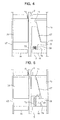
- Fig. 4 is a front view showing the rail pinching portion 5 shown in Fig. 3
- Fig. 5 is a front view showing the rail pinching portion 5 shown in Fig. 3 when actuated.
- a support member 66 is fixed in place inside each groove portion 65.
- Each rail pinching portion 5 is supported on the support member 66.
- each rail pinching portion 5 has a wedge 67 serving as a braking member capable of coming into and out of contact with the car guide rail 2, and an actuating mechanism 68 for pressing the wedge 67 against the car guide rail 2.
- Each actuating mechanism 68 has a drive portion 69 for displacing the wedge 67 with respect to the car 3, and a guide portion 70 fixed onto the vertical frames 63 and for guiding the wedge 67 into or out of contact with the car guide rail 2. Accordingly, the respective actuating mechanisms 68 are actuated independently from each other.
- the guide portion 70 has an inclined surface 71 and a contact surface 72 that are arranged so as to sandwich the car guide rail 2 therebetween.
- the inclined surface 71 is inclined with respect to the car guide rail 2 such that its distance to the car guide rail 2 decreases towards the upper side.
- the contact surface 72 is capable of coming into and out of contact with the car guide rail 2.
- the wedge 67 is displaced upwards with respect to the guide portion 70, the wedge 67 is displaced along the inclined surface 71.
- the wedge 67 and the contact surface 72 are thus displaced so as to come closer to each other, so the car guide rail 2 is pinched between the wedge 67 and the contact surface 72.
- the drive portion 69 has a spring 73 serving as an urging portion for urging the wedge 67 upwards to the guide portion 70 side, and an electromagnet 74 for displacing the wedge 67 downwards so as to move away from the guide portion 70 against the urging of the spring 73 due to an electromagnetic force generated upon supply of power.
- the spring 73 is connected between the support member 66 and the wedge 67.
- the electromagnet 74 is fixed onto the support member 66.
- the emergency stop wirings 17 are connected to the respective electromagnets 74 independently from each other.
- a permanent magnet 75 opposed to the electromagnet 74 is fixed onto the wedge 67.
- Power is supplied to the electromagnet 74 from the battery 12 (see Fig. 1) upon closure of the contact portion 16 (see Fig. 1).
- Each rail pinching portion 5 is actuated when supply of power to the electromagnet 74 is cut off upon opening of the contact portion 16 (see Fig. 1). That is, each wedge 67 is displaced upwards with respect to the car 3 by an elastic restoring force of the spring 73 to be pressed against the car guide rail 2.
- the brake device of the hoisting machine When, for example, the speed of the car 3 rises to reach the first overspeed due to a break in the main rope 4 or the like, the brake device of the hoisting machine is actuated. When the speed of the car 3 further rises to reach the second overspeed even after the actuation of the brake device of the hoisting machine, the contact portion 16 is opened. The supply of power to each electromagnet 74 of each rail pinching portion 5 is thus cut off, so the wedge 67 is displaced upwards with respect to the car 3 due to the urging of the spring 73. Accordingly, the wedge 67 is displaced along the inclined surface 71 while contacting the inclined surface 71 to be brought into contact with and pressed against the car guide rail 2.
- the car 3 is raised while supplying power to the electromagnet 74 by closing the contact portion 16. Accordingly, the wedge 67 is displaced downwards to be separated from the car guide rail 2.
- each rail pinching portion 5 is actuated independently from each other by the respective actuating mechanisms 68, thereby making it possible to dispense with a conventional safety link for connecting the respective actuating mechanisms 68 to each other.
- Each rail pinching portion 5 can be thus arranged in a side portion of the car 3. Accordingly, each rail pinching portion 5 can be arranged within the vertical length of the car 3, thereby reducing the requisite vertical length of an elevating body including the car 3. Therefore, the requisite vertical dimension of the hoistway 1 can be reduced to thereby achieve space saving for the elevator apparatus as a whole.
- a connecting part such as a safety link, which is conventionally required for the connection between the respective rail pinching portions, is removed, so other devices or the like can be mounted to the car up to a weight corresponding to the weight of such a connecting part.
- This enables the car to be readily designed according to the intended use, such as fitting glass to the walls of the car to use the elevator as an observation elevator.
- each rail pinching portion 5 is mounted to the car frame 62, whereby the space for installing each rail pinching portion 5 onto the car 3 can be easily secured. Further, the car 3 can be braked in a stable manner.
- each rail pinching portion 5 is provided at the lower end portion of the vertical frame 63, thereby making it possible to brake the car 3 in a stable manner.
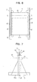
- Fig. 6 is a front view showing an elevator apparatus according to Embodiment 2 of the present invention
- Fig. 7 is a side view showing the elevator apparatus shown in Fig. 6.
- each rail pinching portion 5 is provided in the portion of the groove 65 corresponding to the upper end portion of the vertical frame 63.
- the construction and operation of Embodiment 2 are the same as those of Embodiment 1.
- the safety link conventionally mounted to the car can be dispensed with, so each rail pinching portion 5 can be arranged within the vertical length of the car 3. Therefore, the elevating body, including the car 3, can be reduced in vertical length, thereby achieving space saving for the elevator apparatus as a whole.
- Fig. 8 is a front view showing an elevator apparatus according to Embodiment 3 of the present invention
- Fig. 9 is a side view showing the elevator apparatus shown in Fig. 8.
- each rail pinching portion 5 is provided in the portion of the groove 65 corresponding to the intermediate portion of the vertical frame 63.
- the construction and operation of Embodiment 3 are the same as those of Embodiment 1.
- Fig. 10 is a front view showing a counterweight of an elevator apparatus according to Embodiment 4 of the present invention
- Fig. 11 is a side view showing the counterweight shown in Fig. 10.
- a pair of counterweight guide rails 21 are disposed in the hoistway 1.
- a counterweight 22 is arranged between the counterweight guide rails 21.
- the counterweight 22 has a weight main body 24 including a plurality of unit weights 23, and a weight frame 25 supporting the weight main body 24.
- the weight frame 25 has a lower frame 26 on which the weight main body 24 is placed, an upper frame (upper beam) 27 arranged above the lower frame 26, and a pair of vertical frames (vertical columns) 28 connecting the lower frame 26 and the upper frame 27 to each other.
- the counterweight 22 and the car 3 are suspended by the main rope 4.
- the main rope 4 is connected to the upper frame 27.
- the rail pinching portions 5 that are the same as those of Embodiment 1 are each mounted to each vertical frame 28.
- the rail pinching portions 5 are each provided at the lower end portion of each vertical frame 28 so as to sandwich the counterweight 22 therebetween with respect to the horizontal direction.
- the emergency stop wiring 17 (traveling cable) is electrically connected between the control panel 13 and each counterweight 22. Otherwise, the construction and operation of Embodiment 4 are the same as those of Embodiment 1.
- each rail pinching portion 5 is mounted to the counterweight 22, so each rail pinching portion 5 can be arranged in a side portion of the counterweight 22. Accordingly, the requisite vertical length of the elevating body, including the counterweight 22, can be reduced, thereby achieving space saving for the elevator apparatus as a whole.
- each rail pinching portion 5 is provided at the lower end portion of each vertical frame 28, each rail pinching portion 5 may be provided at the upper end portion or intermediate portion of each vertical frame 28.
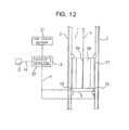
- Fig. 12 is a schematic diagram showing an elevator apparatus according to Embodiment 5 of the present invention.
- a car speed sensor 31 as car speed detecting means for detecting the speed of the car 3.
- An output portion 32 electrically connected to the car speed sensor 31 is mounted in the control panel 13.
- the battery 12 is connected to the output portion 32 via the power cable 14. Electric power for detecting the speed of the car 3 is supplied to the car speed sensor 31 from the output portion 32.
- a speed detection signal from the car speed sensor 31 is inputted to the output portion 32.
- the car 3 is mounted with a pair of rail pinching portions 33 serving as braking means for braking the car 3.
- the respective rail pinching portions 33 are arranged so as to sandwich the car 3 therebetween with respect to the horizontal direction.
- each rail pinching portion 33 is provided at an end portion of a floor portion 3a of the car 3.
- the output portion 32 and each rail pinching portion 33 are electrically connected to each other by the emergency stop wiring 17.
- actuating signals in the form of actuating electric power are outputted from the output portion 32 independently to the respective rail pinching portions 33.
- the respective rail pinching portions 33 are actuated independently from each other when inputted with the actuating signals.
- Fig. 13 is a front view showing the rail pinching portion 33 shown in Fig. 12, and Fig. 14 is a front view showing the rail pinching portion 33 shown in Fig. 13 when actuated.
- the rail pinching portion 33 has a wedge 34 as a braking member capable of coming into and out of contact with the car guide rail 2, an actuator portion 35 connected to a lower portion of the wedge 34, and a guide portion 36 arranged above the wedge 34 and fixed to the car 3.
- the wedge 34 and the actuator portion 35 are provided so as to be vertically movable with respect to the guide portion 36.
- an actuating mechanism 51 includes the actuator portion 35 and the guide portion 36.
- the actuator portion 35 has a cylindrical contact portion 37 capable of coming into and out of contact with the car guide rail 2, a contact-portion displacing mechanism 38 for displacing the contact portion 37 into and out of contact with the car guide rail 2, and a support portion 39 supporting the contact portion 37 and the contact-portion displacing mechanism 38.
- the contact portion 37 is lighter than the wedge 34 such that the contact portion 37 can be readily displaced by the contact-portion displacing mechanism 38.
- the contact-portion displacing mechanism 38 has a movable portion 40, which is capable of reciprocating displacement between a contact position where the contact portion 37 is held in contact with the car guide rail 2 and a released position where the contact portion 37 is separated from the car guide rail 2, and a drive portion 41 for displacing the movable portion 40.
- the support portion 39 and the movable portion 40 are provided with a support guide hole 42 and a movable guide hole 43, respectively.
- the inclination angles of the support guide hole 42 and the movable guide hole 43 with respect to the car guide rail 2 are different from each other.
- the contact portion 37 is slidably fitted in the support guide hole 42 and the movable guide hole 43.
- the contact portion 37 slides within the movable guide hole 43 according to the reciprocating displacement of the movable portion 40, and is displaced along the longitudinal direction of the support guide hole 42.
- the contact portion 37 is moved into and away from contact with the car guide rail 2 at an appropriate angle.
- braking is applied to the wedge 34 and the actuator portion 35, displacing them toward the guide portion 36 side.
- the wedge 34 is slidably fitted in the horizontal guide hole 47. That is, the wedge 34 is capable of reciprocating displacement in the horizontal direction with respect to the support portion 39.
- the guide portion 36 has an inclined surface 44 and a contact surface 45 which are arranged so as to sandwich the car guide rail 2 therebetween.
- the inclined surface 44 is inclined with respect to the car guide rail 2 such that the distance between it and the car guide rail 2 decreases with increasing proximity to its upper portion.
- the contact surface 45 is capable of moving into and away from contact with the car guide rail 2.
- the wedge 34 and the actuator portion 35 are displaced upward with respect to the guide portion 36, the wedge 34 is displaced along the inclined surface 44.
- the wedge 34 and the contact surface 45 are displaced so as to approach each other, and the car guide rail 2 becomes lodged between the wedge 34 and the contact surface 45.
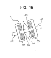
- Fig. 15 is a front view showing the drive portion 41 of Fig. 14.
- the drive portion 41 has a disc spring 46 serving as an urging portion and attached to the movable portion 40, and an electromagnet 48 for displacing the movable portion 40 by an electromagnetic force generated upon supply of electric current thereto.
- the movable portion 40 is fixed to the central portion of the disc spring 46.
- the disc spring 46 is deformed due to the reciprocating displacement of the movable portion 40.
- the urging direction of the disc spring 46 is reversed between the contact position (solid line) and the separated position (broken line).
- the movable portion 40 is retained at the contact or separated position as it is urged by the disc spring 46. That is, the contact or separated state of the contact portion 37 with respect to the car guide rail 2 is retained by the urging of the disc spring 46.
- the electromagnet 48 has a first electromagnetic portion 49 fixed to the movable portion 40, and a second electromagnetic portion 50 opposed to the first electromagnetic portion 49.
- the movable portion 40 is displaceable relative to the second electromagnetic portion 50.
- the emergency stop wiring 17 is connected to the electromagnet 48.
- the first electromagnetic portion 49 and the second electromagnetic portion 50 Upon inputting an actuation signal to the electromagnet 48, the first electromagnetic portion 49 and the second electromagnetic portion 50 generate electromagnetic forces so as to repel each other. That is, upon input of the actuation signal to the electromagnet 48, the first electromagnetic portion 49 is displaced away from contact with the second electromagnetic portion 50, together with the movable portion 40.
- the output portion 32 outputs a recovery signal during the recovery phase. Input of the recovery signal to the electromagnet 48 causes the first electromagnetic portion 49 and the second electromagnetic portion 50 to attract each other. Otherwise, this embodiment is of the same construction as Embodiment 1.
- the urging direction of the disc spring 46 reverses to that for retaining the movable portion 40 at the contact position.
- the contact portion 37 is pressed into contact with the car guide rail 2, thus braking the wedge 34 and the actuator portion 35.
- the guide portion 36 Since the car 3 and the guide portion 36 descend with no braking applied thereon, the guide portion 36 is displaced downward towards the wedge 34 and actuator 35 side. Due to this displacement, the wedge 34 is guided along the inclined surface 44, causing the car guide rail 2 to become lodged between the wedge 34 and the contact surface 45. As the wedge 34 comes into contact with the car guide rail 2, it is displaced further upward to wedge in between the car guide rail 2 and the inclined surface 44. A large frictional force is thus generated between the car guide rail 2 and the wedge 34, and between the car guide rail 2 and the contact surface 45, thus braking the car 3.
- the recovery signal is transmitted from the output portion 32 to the electromagnet 48.
- This causes the first electromagnetic portion 49 and the second electromagnetic portion 50 to attract each other, thus displacing the movable portion 40 to the separated position.
- the contact portion 37 is displaced to be separated away from contact with the car guide rail 2.
- the urging direction of the disc spring 46 reverses, allowing the movable portion 40 to be retained at the separated position.
- the pressing contact of the wedge 34 and the contact surface 45 with the car guide rail 2 is released.
- the respective actuating mechanisms 51 are actuated independently from each other, whereby the respective rail pinching portions 33 can be arranged so as to sandwich the car 3 therebetween with respect to the horizontal direction. Accordingly, the requisite vertical length of the elevating body, including the car 3, can be reduced, thereby achieving space saving for the elevator apparatus as a whole.
- the rail pinching portions 33 are mounted onto the car 3
- the rail pinching portions 33 may be mounted to the counterweight.
- an electrical cable is used as the transmitting means for supplying power from the output portion to the safety device
- a wireless communication device having a transmitter provided to the output portion and a receiver provided to the emergency stop mechanism.
- an optical fiber cable for transmitting light signals may also be used.
- the rail pinching portions apply braking with respect to an overspeed (movement) of the car in the downward direction
- braking may be applied to an overspeed (movement) in the upward direction by vertically inverting those rail pinching portions and fitting them to the car.
Landscapes
- Engineering & Computer Science (AREA)
- Mechanical Engineering (AREA)
- Maintenance And Inspection Apparatuses For Elevators (AREA)
Abstract
A pair of car guide rails for guiding a car are disposed in a hoistway. The car has a cage and a car frame supporting the cage. A pair of rail pinching portions are mounted to the car frame. Each rail pinching portion has a wedge capable of coming into and out of contact with each car guide rail, and an actuating mechanism for pressing the wedge against the car guide rail. The respective actuating mechanisms are actuated independently from each other. The respective rail pinching portions are arranged so as to sandwich the car therebetween with respect to the horizontal direction.
Description
- The present invention relates to a safety device for an elevator for forcibly stopping an elevator car that is being raised and lowered at an abnormal speed.
- Conventional elevator apparatuses employ a safety device for preventing a car from falling.
JP 2002-220171 A - In the safety device for an elevator as described above, however, the safety link connecting between the respective wedges is arranged below the car, so the overall vertical length of an elevating body including the car is enlarged downwards, resulting in an increase in pit depth (the length of the gap between the lower end portion of the elevating body and the bottom portion of the hoistway when the car is at rest at the lowest floor). As a result, the requisite vertical dimension of the hoistway becomes large, which hinders space saving for the elevator apparatus as a whole.
- The present invention has been made to solve the problems as mentioned above, and therefore it is an obj ect of the present invention to provide a safety device for an elevator which enables space saving for an elevator apparatus as a whole.
- According to the present invention, a safety device for an elevator, for braking a car guided by a pair of guide rails includes a pair of rail pinching portions each having: a braking member capable of coming into and out of contact with each of the guide rails; and an actuating mechanism for pressing the braking member against each of the guide rails. The pair of rail pinching portions are mounted onto the car and brake the car with respect to the guide rails upon actuation of the actuating mechanism. The respective actuating mechanisms are actuated independently from each other. And the respective rail pinching portions are arranged so that the rail pinching portions sandwich the car therebetween with respect to a horizontal direction.
-
- Fig. 1 is a schematic diagram showing an elevator apparatus according to Embodiment 1 of the present invention;
- Fig. 2 is a front view showing the car shown in Fig. 1;
- Fig. 3 is a side view showing the car shown in Fig. 2;
- Fig. 4 is a front view showing the rail pinching portion shown in Fig. 3;
- Fig. 5 is a front view showing the rail pinching portion shown in Fig. 3 when actuated;
- Fig. 6 is a front view showing an elevator apparatus according to
Embodiment 2 of the present invention; - Fig. 7 is a side view showing the elevator apparatus shown in Fig. 6;
- Fig. 8 is a front view showing an elevator apparatus according to
Embodiment 3 of the present invention; - Fig. 9 is a side view showing the elevator apparatus shown in Fig. 8;
- Fig. 10 is a front view showing a counterweight of an elevator apparatus according to Embodiment 4 of the present invention;
- Fig. 11 is a side view showing the counterweight shown in Fig. 10;
- Fig. 12 is a schematic diagram showing an elevator apparatus according to
Embodiment 5 of the present invention; - Fig. 13 is a front view showing the rail pinching portion shown in Fig. 12;
- Fig. 14 is a front view showing the rail pinching portion shown in Fig. 13 when actuated;
- Fig. 15 is a front view showing the drive portion of Fig. 14.
- Hereinbelow, preferred embodiments of the present invention will be described with reference to the drawings.
- Fig. 1 is a schematic diagram showing an elevator apparatus according to Embodiment 1 of the present invention. Referring to the drawing, a pair of
car guide rails 2 are disposed in a hoistway 1. Acar 3 is raised and lowered in the hoistway 1 while being guided by thecar guide rails 2. Arranged at an upper end portion of the hoistway 1 is a hoisting machine (not shown) for raising and lowering thecar 3 and a counterweight (not shown). Amain rope 4 is wound around a driving sheave of the hoisting machine. Thecar 3 and the counterweight are suspended in the hoistway 1 by themain rope 4. Thecar 3 is mounted with a pair ofrail pinching portions 5 as braking means opposed to the respectivecar guide rails 2. Braking is applied to thecar 3 upon actuation of therail pinching portions 5. - Further, arranged at an upper end portion of the hoistway 1 is a
governor 6 serving as car speed detecting means for detecting the raising/lowering speed of thecar 3. The governor 6 has a governormain body 7, and a governor sheave 8 rotatable with respect to the governormain body 7. A rotatable tension pulley 9 is arranged at a lower end portion of the hoistway 1. Agovernor rope 10 connected to thecar 3 is looped between the governor sheave 8 and the tension pulley 9. The connecting portion of thegovernor rope 10 with thecar 3 is vertically reciprocated together with thecar 3. The governor sheave 8 and the tension pulley 9 are thus rotated at a speed corresponding to the raising/lowering speed of thecar 3. - The governor 6 is adapted to actuate a brake device of the hoisting machine when the raising/lowering speed of the
car 3 reaches a preset overspeed. Further, thegovernor 6 is provided with a switch portion 11 serving as an output portion for outputting an actuating signal to therail pinching portions 5 when the lowering speed of thecar 3 reaches a second overspeed (set overspeed) that is higher than the first overspeed. The switch portion 11 has acontact portion 16 that is mechanically opened and closed by means of an overspeed lever displaced according to the centrifugal force of the governor sheave 8 being rotated. Thecontact portion 16 is electrically connected to abattery 12, which is an uninterruptible power supply capable of supplying power even in the event of a power failure, and to acontrol panel 13 for controlling the operation of an elevator through apower cable 14 and a connectingcable 15, respectively. - A control cable (traveling cable) is connected between the
car 3 and thecontrol panel 13. The control cable includes, in addition to a plurality of power lines and signal lines, anemergency stop wiring 17 that is electrically connected between thecontrol panel 13 and eachrail pinching portion 5. Upon closure of thecontact portion 16, electric power from thebattery 12 is supplied to eachrail pinching portion 5 by way of thepower cable 14, the switching portion 11, the connectingcable 15, a power supply circuit inside thecontrol panel 13, and theemergency stop wiring 17. It should be noted that transmitting means includes the connectingcable 15, the power supply circuit inside thecontrol panel 13, and theemergency stop wiring 17. - Fig. 2 is a front view showing the
car 3 shown in Fig. 1, and Fig. 3 is a side view showing thecar 3 shown in Fig. 2. Referring to the drawings, thecar 3 has acage 61, and acar frame 62 supporting thecage 61. Thecar frame 62 has a pair of vertical frames (vertical columns) 63, which are each arranged between thecage 61 and eachcar guide rail 2 and extend upwards from afloor portion 61a of thecage 61, and an upper frame (upper beam) 64 arranged above thecage 61 and extending horizontally between the upper end portions of the respectivevertical frames 63. - The
vertical frames 63 are each provided with agroove portion 65 extending in the vertical direction along thecar guide rail 2. A part of eachcar guide rail 2 is arranged within eachgroove portion 65. - The respective
rail pinching portions 5 are mounted to thecar frame 62 so as to sandwich thecar 3 therebetween with respect to the horizontal direction. That is, eachrail pinching portion 5 is arranged at a height between the upper end portion and lower end portion of thecar 3 and on both sides with respect to the width direction of thecar 3. Further, eachrail pinching portion 5 is provided in thegroove 65. Further, eachrail pinching portion 5 is provided at the lower end portion of eachvertical frame 63. In this example, eachrail pinching portion 5 is arranged at the same height as thefloor portion 61a. - Fig. 4 is a front view showing the
rail pinching portion 5 shown in Fig. 3, and Fig. 5 is a front view showing therail pinching portion 5 shown in Fig. 3 when actuated. Referring to the drawings, asupport member 66 is fixed in place inside eachgroove portion 65. Eachrail pinching portion 5 is supported on thesupport member 66. Further, eachrail pinching portion 5 has awedge 67 serving as a braking member capable of coming into and out of contact with thecar guide rail 2, and anactuating mechanism 68 for pressing thewedge 67 against thecar guide rail 2. Eachactuating mechanism 68 has adrive portion 69 for displacing thewedge 67 with respect to thecar 3, and aguide portion 70 fixed onto thevertical frames 63 and for guiding thewedge 67 into or out of contact with thecar guide rail 2. Accordingly, therespective actuating mechanisms 68 are actuated independently from each other. - The
guide portion 70 has aninclined surface 71 and acontact surface 72 that are arranged so as to sandwich thecar guide rail 2 therebetween. Theinclined surface 71 is inclined with respect to thecar guide rail 2 such that its distance to thecar guide rail 2 decreases towards the upper side. Thecontact surface 72 is capable of coming into and out of contact with thecar guide rail 2. As thewedge 67 is displaced upwards with respect to theguide portion 70, thewedge 67 is displaced along theinclined surface 71. Thewedge 67 and thecontact surface 72 are thus displaced so as to come closer to each other, so thecar guide rail 2 is pinched between thewedge 67 and thecontact surface 72. - The
drive portion 69 has aspring 73 serving as an urging portion for urging thewedge 67 upwards to theguide portion 70 side, and anelectromagnet 74 for displacing thewedge 67 downwards so as to move away from theguide portion 70 against the urging of thespring 73 due to an electromagnetic force generated upon supply of power. - The
spring 73 is connected between thesupport member 66 and thewedge 67. Theelectromagnet 74 is fixed onto thesupport member 66. The emergency stop wirings 17 are connected to therespective electromagnets 74 independently from each other. Apermanent magnet 75 opposed to theelectromagnet 74 is fixed onto thewedge 67. Power is supplied to theelectromagnet 74 from the battery 12 (see Fig. 1) upon closure of the contact portion 16 (see Fig. 1). Eachrail pinching portion 5 is actuated when supply of power to theelectromagnet 74 is cut off upon opening of the contact portion 16 (see Fig. 1). That is, eachwedge 67 is displaced upwards with respect to thecar 3 by an elastic restoring force of thespring 73 to be pressed against thecar guide rail 2. - Next, operation will be described. During the normal operation, the
contact portion 16 is closed. Accordingly, electric power from thebattery 12 is supplied to eachelectromagnet 74. Eachwedge 67 is sucked and held onto theelectromagnet 74 by the electromagnetic force generated due to the supply of power to be separated from the car guide rail 2 (Fig. 4). - When, for example, the speed of the
car 3 rises to reach the first overspeed due to a break in themain rope 4 or the like, the brake device of the hoisting machine is actuated. When the speed of thecar 3 further rises to reach the second overspeed even after the actuation of the brake device of the hoisting machine, thecontact portion 16 is opened. The supply of power to eachelectromagnet 74 of eachrail pinching portion 5 is thus cut off, so thewedge 67 is displaced upwards with respect to thecar 3 due to the urging of thespring 73. Accordingly, thewedge 67 is displaced along theinclined surface 71 while contacting theinclined surface 71 to be brought into contact with and pressed against thecar guide rail 2. Thereafter, thewedge 67 is displaced further upwards, and thecontact surface 72 is brought into contact with thecar guide rail 2. Thewedge 67 is thus pinched between thecar guide rail 2 and theguide portion 70, so a large friction force is generated between thecar guide rail 2 and each of thewedge 67 and thecontact surface 72, thereby braking the car 3 (Fig. 5). - To release the braking on the
car 3, thecar 3 is raised while supplying power to theelectromagnet 74 by closing thecontact portion 16. Accordingly, thewedge 67 is displaced downwards to be separated from thecar guide rail 2. - In the safety device for an elevator as described above, the respective
rail pinching portions 5 are actuated independently from each other by therespective actuating mechanisms 68, thereby making it possible to dispense with a conventional safety link for connecting therespective actuating mechanisms 68 to each other. Eachrail pinching portion 5 can be thus arranged in a side portion of thecar 3. Accordingly, eachrail pinching portion 5 can be arranged within the vertical length of thecar 3, thereby reducing the requisite vertical length of an elevating body including thecar 3. Therefore, the requisite vertical dimension of the hoistway 1 can be reduced to thereby achieve space saving for the elevator apparatus as a whole. - Further, a connecting part such as a safety link, which is conventionally required for the connection between the respective rail pinching portions, is removed, so other devices or the like can be mounted to the car up to a weight corresponding to the weight of such a connecting part. This enables the car to be readily designed according to the intended use, such as fitting glass to the walls of the car to use the elevator as an observation elevator.
- Further, each
rail pinching portion 5 is mounted to thecar frame 62, whereby the space for installing eachrail pinching portion 5 onto thecar 3 can be easily secured. Further, thecar 3 can be braked in a stable manner. - Further, each
rail pinching portion 5 is provided at the lower end portion of thevertical frame 63, thereby making it possible to brake thecar 3 in a stable manner. - Fig. 6 is a front view showing an elevator apparatus according to
Embodiment 2 of the present invention, and Fig. 7 is a side view showing the elevator apparatus shown in Fig. 6. In this example, eachrail pinching portion 5 is provided in the portion of thegroove 65 corresponding to the upper end portion of thevertical frame 63. Otherwise, the construction and operation ofEmbodiment 2 are the same as those of Embodiment 1. - With such an elevator apparatus as well, the safety link conventionally mounted to the car can be dispensed with, so each
rail pinching portion 5 can be arranged within the vertical length of thecar 3. Therefore, the elevating body, including thecar 3, can be reduced in vertical length, thereby achieving space saving for the elevator apparatus as a whole. - Fig. 8 is a front view showing an elevator apparatus according to
Embodiment 3 of the present invention, and Fig. 9 is a side view showing the elevator apparatus shown in Fig. 8. In this example, eachrail pinching portion 5 is provided in the portion of thegroove 65 corresponding to the intermediate portion of thevertical frame 63. Otherwise, the construction and operation ofEmbodiment 3 are the same as those of Embodiment 1. - With the above-described elevator apparatus as well, it is possible to achieve space saving for the elevator apparatus as a whole in the same manner as in
Embodiments 1, 2. - Fig. 10 is a front view showing a counterweight of an elevator apparatus according to
Embodiment 4 of the present invention, and Fig. 11 is a side view showing the counterweight shown in Fig. 10. Referring to the drawings, a pair ofcounterweight guide rails 21 are disposed in the hoistway 1. Acounterweight 22 is arranged between the counterweight guide rails 21. Thecounterweight 22 has a weightmain body 24 including a plurality ofunit weights 23, and aweight frame 25 supporting the weightmain body 24. - The
weight frame 25 has alower frame 26 on which the weightmain body 24 is placed, an upper frame (upper beam) 27 arranged above thelower frame 26, and a pair of vertical frames (vertical columns) 28 connecting thelower frame 26 and theupper frame 27 to each other. Thecounterweight 22 and thecar 3 are suspended by themain rope 4. Themain rope 4 is connected to theupper frame 27. - The
rail pinching portions 5 that are the same as those of Embodiment 1 are each mounted to eachvertical frame 28. Therail pinching portions 5 are each provided at the lower end portion of eachvertical frame 28 so as to sandwich thecounterweight 22 therebetween with respect to the horizontal direction. The emergency stop wiring 17 (traveling cable) is electrically connected between thecontrol panel 13 and eachcounterweight 22. Otherwise, the construction and operation ofEmbodiment 4 are the same as those of Embodiment 1. - In the elevator apparatus as described above, each
rail pinching portion 5 is mounted to thecounterweight 22, so eachrail pinching portion 5 can be arranged in a side portion of thecounterweight 22. Accordingly, the requisite vertical length of the elevating body, including thecounterweight 22, can be reduced, thereby achieving space saving for the elevator apparatus as a whole. - While in the above-described example each
rail pinching portion 5 is provided at the lower end portion of eachvertical frame 28, eachrail pinching portion 5 may be provided at the upper end portion or intermediate portion of eachvertical frame 28. - Fig. 12 is a schematic diagram showing an elevator apparatus according to
Embodiment 5 of the present invention. Referring to the drawing, provided in the hoistway 1 is acar speed sensor 31 as car speed detecting means for detecting the speed of thecar 3. Anoutput portion 32 electrically connected to thecar speed sensor 31 is mounted in thecontrol panel 13. Thebattery 12 is connected to theoutput portion 32 via thepower cable 14. Electric power for detecting the speed of thecar 3 is supplied to thecar speed sensor 31 from theoutput portion 32. A speed detection signal from thecar speed sensor 31 is inputted to theoutput portion 32. - The
car 3 is mounted with a pair ofrail pinching portions 33 serving as braking means for braking thecar 3. The respectiverail pinching portions 33 are arranged so as to sandwich thecar 3 therebetween with respect to the horizontal direction. In this example, eachrail pinching portion 33 is provided at an end portion of a floor portion 3a of thecar 3. - The
output portion 32 and eachrail pinching portion 33 are electrically connected to each other by theemergency stop wiring 17. When the speed of thecar 3 becomes the second overspeed, actuating signals in the form of actuating electric power are outputted from theoutput portion 32 independently to the respectiverail pinching portions 33. The respectiverail pinching portions 33 are actuated independently from each other when inputted with the actuating signals. - Fig. 13 is a front view showing the
rail pinching portion 33 shown in Fig. 12, and Fig. 14 is a front view showing therail pinching portion 33 shown in Fig. 13 when actuated. Referring to the drawings, therail pinching portion 33 has awedge 34 as a braking member capable of coming into and out of contact with thecar guide rail 2, anactuator portion 35 connected to a lower portion of thewedge 34, and aguide portion 36 arranged above thewedge 34 and fixed to thecar 3. Thewedge 34 and theactuator portion 35 are provided so as to be vertically movable with respect to theguide portion 36. As thewedge 34 is displaced upwards with respect to theguide portion 36, that is, to theguide portion 36 side, thewedge 34 is guided by theguide portion 36 into contact with thecar guide rail 2. It should be noted that anactuating mechanism 51 includes theactuator portion 35 and theguide portion 36. - The
actuator portion 35 has acylindrical contact portion 37 capable of coming into and out of contact with thecar guide rail 2, a contact-portion displacing mechanism 38 for displacing thecontact portion 37 into and out of contact with thecar guide rail 2, and asupport portion 39 supporting thecontact portion 37 and the contact-portion displacing mechanism 38. Thecontact portion 37 is lighter than thewedge 34 such that thecontact portion 37 can be readily displaced by the contact-portion displacing mechanism 38. The contact-portion displacing mechanism 38 has amovable portion 40, which is capable of reciprocating displacement between a contact position where thecontact portion 37 is held in contact with thecar guide rail 2 and a released position where thecontact portion 37 is separated from thecar guide rail 2, and adrive portion 41 for displacing themovable portion 40. - The
support portion 39 and themovable portion 40 are provided with asupport guide hole 42 and amovable guide hole 43, respectively. The inclination angles of thesupport guide hole 42 and themovable guide hole 43 with respect to thecar guide rail 2 are different from each other. Thecontact portion 37 is slidably fitted in thesupport guide hole 42 and themovable guide hole 43. Thecontact portion 37 slides within themovable guide hole 43 according to the reciprocating displacement of themovable portion 40, and is displaced along the longitudinal direction of thesupport guide hole 42. As a result, thecontact portion 37 is moved into and away from contact with thecar guide rail 2 at an appropriate angle. When thecontact portion 37 comes into contact with thecar guide rail 2 as thecar 3 descends, braking is applied to thewedge 34 and theactuator portion 35, displacing them toward theguide portion 36 side. - Mounted on the upperside of the
support portion 39 is ahorizontal guide hole 47 extending in the horizontal direction. Thewedge 34 is slidably fitted in thehorizontal guide hole 47. That is, thewedge 34 is capable of reciprocating displacement in the horizontal direction with respect to thesupport portion 39. - The
guide portion 36 has aninclined surface 44 and acontact surface 45 which are arranged so as to sandwich thecar guide rail 2 therebetween. Theinclined surface 44 is inclined with respect to thecar guide rail 2 such that the distance between it and thecar guide rail 2 decreases with increasing proximity to its upper portion. Thecontact surface 45 is capable of moving into and away from contact with thecar guide rail 2. As thewedge 34 and theactuator portion 35 are displaced upward with respect to theguide portion 36, thewedge 34 is displaced along theinclined surface 44. As a result, thewedge 34 and thecontact surface 45 are displaced so as to approach each other, and thecar guide rail 2 becomes lodged between thewedge 34 and thecontact surface 45. - Fig. 15 is a front view showing the
drive portion 41 of Fig. 14. Referring to the drawing, thedrive portion 41 has adisc spring 46 serving as an urging portion and attached to themovable portion 40, and anelectromagnet 48 for displacing themovable portion 40 by an electromagnetic force generated upon supply of electric current thereto. - The
movable portion 40 is fixed to the central portion of thedisc spring 46. Thedisc spring 46 is deformed due to the reciprocating displacement of themovable portion 40. As thedisc spring 46 is deformed due to the displacement of themovable portion 40, the urging direction of thedisc spring 46 is reversed between the contact position (solid line) and the separated position (broken line). Themovable portion 40 is retained at the contact or separated position as it is urged by thedisc spring 46. That is, the contact or separated state of thecontact portion 37 with respect to thecar guide rail 2 is retained by the urging of thedisc spring 46. - The
electromagnet 48 has a firstelectromagnetic portion 49 fixed to themovable portion 40, and a secondelectromagnetic portion 50 opposed to the firstelectromagnetic portion 49. Themovable portion 40 is displaceable relative to the secondelectromagnetic portion 50. Theemergency stop wiring 17 is connected to theelectromagnet 48. Upon inputting an actuation signal to theelectromagnet 48, the firstelectromagnetic portion 49 and the secondelectromagnetic portion 50 generate electromagnetic forces so as to repel each other. That is, upon input of the actuation signal to theelectromagnet 48, the firstelectromagnetic portion 49 is displaced away from contact with the secondelectromagnetic portion 50, together with themovable portion 40. - It should be noted that for recovery after the actuation of the
rail pinching portion 33, theoutput portion 32 outputs a recovery signal during the recovery phase. Input of the recovery signal to theelectromagnet 48 causes the firstelectromagnetic portion 49 and the secondelectromagnetic portion 50 to attract each other. Otherwise, this embodiment is of the same construction as Embodiment 1. - Next, operation is described. During normal operation, the
movable portion 40 is located at the separated position, and thecontact portion 37 is urged by thedisc spring 46 to be separated away from contact with thecar guide rail 2. With thecontact portion 37 thus being separated from thecar guide rail 2, thewedge 34 is separated from theguide portion 36, thus maintaining the distance between thewedge 34 and theguide portion 36. - When the speed detected by the
car speed sensor 31 reaches the first overspeed, this actuates the braking device of the hoisting machine. When the speed of thecar 3 continues to rise thereafter and the speed as detected by thecar speed sensor 31 reaches the second overspeed, an actuation signal is output from theoutput portion 32 to eachrail pinching portion 33. Inputting this actuation signal to theelectromagnet 48 triggers the firstelectromagnetic portion 49 and the secondelectromagnetic portion 50 to repel each other. The electromagnetic repulsion force thus generated causes themovable portion 40 to be displaced into the contact position. As this happens, thecontact portion 37 is displaced into contact with thecar guide rail 2. By the time themovable portion 40 reaches the contact position, the urging direction of thedisc spring 46 reverses to that for retaining themovable portion 40 at the contact position. As a result, thecontact portion 37 is pressed into contact with thecar guide rail 2, thus braking thewedge 34 and theactuator portion 35. - Since the
car 3 and theguide portion 36 descend with no braking applied thereon, theguide portion 36 is displaced downward towards thewedge 34 andactuator 35 side. Due to this displacement, thewedge 34 is guided along theinclined surface 44, causing thecar guide rail 2 to become lodged between thewedge 34 and thecontact surface 45. As thewedge 34 comes into contact with thecar guide rail 2, it is displaced further upward to wedge in between thecar guide rail 2 and theinclined surface 44. A large frictional force is thus generated between thecar guide rail 2 and thewedge 34, and between thecar guide rail 2 and thecontact surface 45, thus braking thecar 3. - During the recovery phase, the recovery signal is transmitted from the
output portion 32 to theelectromagnet 48. This causes the firstelectromagnetic portion 49 and the secondelectromagnetic portion 50 to attract each other, thus displacing themovable portion 40 to the separated position. As this happens, thecontact portion 37 is displaced to be separated away from contact with thecar guide rail 2. By the time themovable portion 40 reaches the separated position, the urging direction of thedisc spring 46 reverses, allowing themovable portion 40 to be retained at the separated position. As thecar 3 ascends in this state, the pressing contact of thewedge 34 and thecontact surface 45 with thecar guide rail 2 is released. - In the safety device for an elevator constructed as described above, the
respective actuating mechanisms 51 are actuated independently from each other, whereby the respectiverail pinching portions 33 can be arranged so as to sandwich thecar 3 therebetween with respect to the horizontal direction. Accordingly, the requisite vertical length of the elevating body, including thecar 3, can be reduced, thereby achieving space saving for the elevator apparatus as a whole. - While in the above-described example the
rail pinching portions 33 are mounted onto thecar 3, therail pinching portions 33 may be mounted to the counterweight. - While in the above-described embodiments an electrical cable is used as the transmitting means for supplying power from the output portion to the safety device, it is also possible to use a wireless communication device having a transmitter provided to the output portion and a receiver provided to the emergency stop mechanism. Further, an optical fiber cable for transmitting light signals may also be used.
- Further, while in the above-described embodiments the rail pinching portions apply braking with respect to an overspeed (movement) of the car in the downward direction, braking may be applied to an overspeed (movement) in the upward direction by vertically inverting those rail pinching portions and fitting them to the car.
Claims (3)
- A safety device for an elevator, for braking a car guided by a pair of guide rails, comprising:a pair of rail pinching portions each having: a braking member capable of coming into and out of contact with each of the guide rails; and an actuating mechanism for pressing the braking member against each of the guide rails, the pair of rail pinching portions being mounted onto the car and braking the car with respect to the guide rails upon actuation of the actuating mechanism,the safety device being characterized in that:the respective actuating mechanisms are actuated independently from each other; andthe respective rail pinching portions are arranged so that the rail pinching portions sandwich the car therebetween with respect to a horizontal direction.
- A safety device for an elevator according to Claim 1,
characterized in that:the car has a cage and a car frame surrounding the car; andthe respective rail pinching portions are mounted onto the car frame. - A safety device for an elevator, for braking a counterweight guided by a pair of guide rails, comprising:a pair of rail pinching portions each having: a braking member capable of coming into and out of contact with each of the guide rails; and an actuating mechanism for pressing the braking member against each of the guide rails, the pair of rail pinching portions being mounted onto the counterweight and braking the counterweight with respect to the guide rails,the safety device being characterized in that:the respective actuating mechanisms are actuated independently from each other; andthe respective rail pinching portions are arranged so that the rail pinching portions sandwich the counterweight therebetween with respect to a horizontal direction.
Applications Claiming Priority (1)
| Application Number | Priority Date | Filing Date | Title |
|---|---|---|---|
| PCT/JP2004/007225 WO2005113402A1 (en) | 2004-05-20 | 2004-05-20 | Emergency stop device for elevator |
Publications (2)
| Publication Number | Publication Date |
|---|---|
| EP1748017A1 true EP1748017A1 (en) | 2007-01-31 |
| EP1748017A4 EP1748017A4 (en) | 2010-01-27 |
Family
ID=35428343
Family Applications (1)
| Application Number | Title | Priority Date | Filing Date |
|---|---|---|---|
| EP04734136A Withdrawn EP1748017A4 (en) | 2004-05-20 | 2004-05-20 | EMERGENCY STOP DEVICE FOR ELEVATOR |
Country Status (4)
| Country | Link |
|---|---|
| EP (1) | EP1748017A4 (en) |
| JP (1) | JP4890246B2 (en) |
| CN (1) | CN1791548B (en) |
| WO (1) | WO2005113402A1 (en) |
Cited By (4)
| Publication number | Priority date | Publication date | Assignee | Title |
|---|---|---|---|---|
| CN102465982A (en) * | 2010-10-29 | 2012-05-23 | 武汉市江汉石油机械有限公司 | Heavy-load free falling body brake device |
| DE102014004356A1 (en) * | 2014-03-27 | 2015-10-01 | Thyssenkrupp Elevator Ag | Braking device for a car of an elevator system |
| EP3608276A1 (en) * | 2018-08-10 | 2020-02-12 | Otis Elevator Company | Elevator electrical safety actuator |
| EP3286123B1 (en) | 2015-04-21 | 2020-04-08 | thyssenkrupp Stairlifts B.V. | Stair lift |
Families Citing this family (6)
| Publication number | Priority date | Publication date | Assignee | Title |
|---|---|---|---|---|
| JP2008254837A (en) * | 2007-04-02 | 2008-10-23 | Mitsubishi Electric Corp | Elevator emergency stop device |
| JP5260257B2 (en) * | 2008-12-18 | 2013-08-14 | 三菱重工業株式会社 | Braking control mechanism |
| WO2017023926A1 (en) | 2015-08-04 | 2017-02-09 | Otis Elevator Company | Device and method for actuating an elevator safety brake |
| CN107089579A (en) * | 2017-06-23 | 2017-08-25 | 天奥电梯(中国)有限公司 | A kind of simple goods elevator |
| CN107601204A (en) * | 2017-10-19 | 2018-01-19 | 中联重科股份有限公司 | lift |
| EP3608273B1 (en) * | 2018-08-10 | 2022-09-28 | Otis Elevator Company | Elevator safety gear actuation device |
Family Cites Families (16)
| Publication number | Priority date | Publication date | Assignee | Title |
|---|---|---|---|---|
| JPS5453451A (en) * | 1977-10-06 | 1979-04-26 | Toshiba Corp | Emergency elevator cage stopping device |
| JPS5921181Y2 (en) * | 1979-05-04 | 1984-06-21 | 三菱電機株式会社 | Emergency stop device for elevating objects |
| JPS56127572A (en) * | 1980-03-11 | 1981-10-06 | Daifuku Machinery Works | Preventing device for falling of lifting gear |
| FR2573741B3 (en) * | 1984-11-23 | 1987-03-20 | Otis Elevator Co | BRAKE AND SAFETY DEVICE FOR ELEVATOR |
| JPH0761832B2 (en) * | 1989-05-29 | 1995-07-05 | 三菱電機株式会社 | Linear motor drive elevator |
| JP2586203B2 (en) * | 1990-11-08 | 1997-02-26 | 三菱電機株式会社 | Braking device for linear motor driven elevator |
| CA2072187C (en) * | 1992-06-23 | 1996-09-03 | Dermot Camack | Emergency braking systems for hoists |
| JP2569389Y2 (en) * | 1992-07-09 | 1998-04-22 | 株式会社共立 | Brake device for lifting lift for multi-story parking equipment |
| ATE175946T1 (en) * | 1993-10-18 | 1999-02-15 | Inventio Ag | BRAKE SAFETY DEVICE FOR AN ELEVATOR CABIN |
| JPH09202558A (en) * | 1996-01-30 | 1997-08-05 | Mitsubishi Denki Bill Techno Service Kk | Derail preventing device for elevator |
| JP2000007245A (en) * | 1998-06-22 | 2000-01-11 | Mitsubishi Electric Corp | Elevator governor |
| US6161653A (en) * | 1998-12-22 | 2000-12-19 | Otis Elevator Company | Ropeless governor mechanism for an elevator car |
| FI111241B (en) * | 1999-09-23 | 2003-06-30 | Kone Corp | Procedure for braking a drive pulley lift, drive pulley lift and use of a backup power source |
| WO2003008317A1 (en) * | 2001-06-29 | 2003-01-30 | Mitsubishi Denki Kabushiki Kaisha | Emergency brake device of elevator |
| EP1323660B1 (en) * | 2001-12-24 | 2017-01-04 | Inventio AG | Safety brake for elevator system |
| EP1549582B1 (en) * | 2002-10-09 | 2012-10-03 | Otis Elevator Company | Combined elevator guiding and safety braking device |
-
2004
- 2004-05-20 JP JP2006519169A patent/JP4890246B2/en not_active Expired - Fee Related
- 2004-05-20 CN CN2004800134918A patent/CN1791548B/en not_active Expired - Fee Related
- 2004-05-20 WO PCT/JP2004/007225 patent/WO2005113402A1/en not_active Ceased
- 2004-05-20 EP EP04734136A patent/EP1748017A4/en not_active Withdrawn
Cited By (6)
| Publication number | Priority date | Publication date | Assignee | Title |
|---|---|---|---|---|
| CN102465982A (en) * | 2010-10-29 | 2012-05-23 | 武汉市江汉石油机械有限公司 | Heavy-load free falling body brake device |
| CN102465982B (en) * | 2010-10-29 | 2013-11-20 | 武汉市江汉石油机械有限公司 | Heavy-load free falling body brake device |
| DE102014004356A1 (en) * | 2014-03-27 | 2015-10-01 | Thyssenkrupp Elevator Ag | Braking device for a car of an elevator system |
| EP3286123B1 (en) | 2015-04-21 | 2020-04-08 | thyssenkrupp Stairlifts B.V. | Stair lift |
| EP3608276A1 (en) * | 2018-08-10 | 2020-02-12 | Otis Elevator Company | Elevator electrical safety actuator |
| CN110817657A (en) * | 2018-08-10 | 2020-02-21 | 奥的斯电梯公司 | Elevator electric safety actuator |
Also Published As
| Publication number | Publication date |
|---|---|
| CN1791548A (en) | 2006-06-21 |
| JP4890246B2 (en) | 2012-03-07 |
| EP1748017A4 (en) | 2010-01-27 |
| WO2005113402A1 (en) | 2005-12-01 |
| CN1791548B (en) | 2011-03-30 |
| JPWO2005113402A1 (en) | 2008-03-27 |
Similar Documents
| Publication | Publication Date | Title |
|---|---|---|
| EP1604935B1 (en) | Elevator device, and emergency stop device for elevator | |
| EP1749784B1 (en) | Emergency stop device of elevator | |
| US7614481B2 (en) | Elevator apparatus including a safety control portion that detects an abnormality | |
| US7540358B2 (en) | Elevator apparatus including main and auxiliary sensors | |
| EP1748017A1 (en) | Emergency stop device for elevator | |
| EP1741659B1 (en) | Elevator apparatus | |
| JP2010254480A (en) | Elevator equipment | |
| KR100569799B1 (en) | Counterweight | |
| CN100453440C (en) | Method for driving actuator and driving circuit of actuator | |
| KR20060057572A (en) | Elevator emergency stop device | |
| EP1741657A1 (en) | Elevator apparatus | |
| KR20160146302A (en) | Apparatus for elevator emergency stop | |
| KR100813767B1 (en) | Elevator safety device | |
| KR100681591B1 (en) | Elevator device | |
| HK1141501A1 (en) | Braking device for elevator | |
| HK1141501B (en) | Braking device for elevator |
Legal Events
| Date | Code | Title | Description |
|---|---|---|---|
| PUAI | Public reference made under article 153(3) epc to a published international application that has entered the european phase |
Free format text: ORIGINAL CODE: 0009012 |
|
| 17P | Request for examination filed |
Effective date: 20051209 |
|
| AK | Designated contracting states |
Kind code of ref document: A1 Designated state(s): DE FR NL |
|
| DAX | Request for extension of the european patent (deleted) | ||
| RBV | Designated contracting states (corrected) |
Designated state(s): DE FR NL |
|
| A4 | Supplementary search report drawn up and despatched |
Effective date: 20091230 |
|
| 17Q | First examination report despatched |
Effective date: 20130802 |
|
| STAA | Information on the status of an ep patent application or granted ep patent |
Free format text: STATUS: THE APPLICATION IS DEEMED TO BE WITHDRAWN |
|
| 18D | Application deemed to be withdrawn |
Effective date: 20131213 |