CN110817657A - Elevator electric safety actuator - Google Patents
Elevator electric safety actuator Download PDFInfo
- Publication number
- CN110817657A CN110817657A CN201910735680.4A CN201910735680A CN110817657A CN 110817657 A CN110817657 A CN 110817657A CN 201910735680 A CN201910735680 A CN 201910735680A CN 110817657 A CN110817657 A CN 110817657A
- Authority
- CN
- China
- Prior art keywords
- car
- elevator
- electromechanical actuator
- safety brake
- elevator car
- Prior art date
- Legal status (The legal status is an assumption and is not a legal conclusion. Google has not performed a legal analysis and makes no representation as to the accuracy of the status listed.)
- Pending
Links
Images


Classifications
-
- B—PERFORMING OPERATIONS; TRANSPORTING
- B66—HOISTING; LIFTING; HAULING
- B66B—ELEVATORS; ESCALATORS OR MOVING WALKWAYS
- B66B5/00—Applications of checking, fault-correcting, or safety devices in elevators
- B66B5/02—Applications of checking, fault-correcting, or safety devices in elevators responsive to abnormal operating conditions
- B66B5/16—Braking or catch devices operating between cars, cages, or skips and fixed guide elements or surfaces in hoistway or well
- B66B5/18—Braking or catch devices operating between cars, cages, or skips and fixed guide elements or surfaces in hoistway or well and applying frictional retarding forces
-
- B—PERFORMING OPERATIONS; TRANSPORTING
- B66—HOISTING; LIFTING; HAULING
- B66B—ELEVATORS; ESCALATORS OR MOVING WALKWAYS
- B66B11/00—Main component parts of lifts in, or associated with, buildings or other structures
- B66B11/02—Cages, i.e. cars
- B66B11/0226—Constructional features, e.g. walls assembly, decorative panels, comfort equipment, thermal or sound insulation
-
- B—PERFORMING OPERATIONS; TRANSPORTING
- B66—HOISTING; LIFTING; HAULING
- B66B—ELEVATORS; ESCALATORS OR MOVING WALKWAYS
- B66B1/00—Control systems of elevators in general
- B66B1/24—Control systems with regulation, i.e. with retroactive action, for influencing travelling speed, acceleration, or deceleration
- B66B1/28—Control systems with regulation, i.e. with retroactive action, for influencing travelling speed, acceleration, or deceleration electrical
-
- B—PERFORMING OPERATIONS; TRANSPORTING
- B66—HOISTING; LIFTING; HAULING
- B66B—ELEVATORS; ESCALATORS OR MOVING WALKWAYS
- B66B1/00—Control systems of elevators in general
- B66B1/34—Details, e.g. call counting devices, data transmission from car to control system, devices giving information to the control system
- B66B1/3415—Control system configuration and the data transmission or communication within the control system
- B66B1/3446—Data transmission or communication within the control system
-
- B—PERFORMING OPERATIONS; TRANSPORTING
- B66—HOISTING; LIFTING; HAULING
- B66B—ELEVATORS; ESCALATORS OR MOVING WALKWAYS
- B66B11/00—Main component parts of lifts in, or associated with, buildings or other structures
- B66B11/02—Cages, i.e. cars
- B66B11/0206—Car frames
-
- B—PERFORMING OPERATIONS; TRANSPORTING
- B66—HOISTING; LIFTING; HAULING
- B66B—ELEVATORS; ESCALATORS OR MOVING WALKWAYS
- B66B17/00—Hoistway equipment
- B66B17/12—Counterpoises
-
- B—PERFORMING OPERATIONS; TRANSPORTING
- B66—HOISTING; LIFTING; HAULING
- B66B—ELEVATORS; ESCALATORS OR MOVING WALKWAYS
- B66B5/00—Applications of checking, fault-correcting, or safety devices in elevators
- B66B5/02—Applications of checking, fault-correcting, or safety devices in elevators responsive to abnormal operating conditions
- B66B5/04—Applications of checking, fault-correcting, or safety devices in elevators responsive to abnormal operating conditions for detecting excessive speed
-
- B—PERFORMING OPERATIONS; TRANSPORTING
- B66—HOISTING; LIFTING; HAULING
- B66B—ELEVATORS; ESCALATORS OR MOVING WALKWAYS
- B66B5/00—Applications of checking, fault-correcting, or safety devices in elevators
- B66B5/02—Applications of checking, fault-correcting, or safety devices in elevators responsive to abnormal operating conditions
- B66B5/16—Braking or catch devices operating between cars, cages, or skips and fixed guide elements or surfaces in hoistway or well
Abstract
The invention describes an elevator system. An elevator system includes an elevator car movable along guide rails within a hoistway. The elevator car has a car frame with a platform, a ceiling and car structural components. The distance between the platform and the ceiling is defined as the carHeight H of carriageC. An overspeed safety system is provided and included at car height HCA first and a second safety brake and a first and a second electromechanical actuator internally positioned within the car structural component. The safety brake is operable to engage the guide rail to stop movement of the elevator car.
Description
Technical Field
The subject matter disclosed herein relates generally to elevator systems and, more particularly, to safety systems installed in locations that are not typically employed.
Background
Certain components of the elevator car fit outside of the elevator car and, as such, can be difficult for a mechanic to access and perform maintenance on. For example, the safety block engaged with the guide rail may be located at the top of a column or other structural component of the frame of the elevator car, and thus may require access into the hoistway to perform maintenance thereon. Further, such components may require additional space for the elevator car to operate within the hoistway.
For example, conventional safety requirements for an elevator hoistway have resulted in a large space at both the top and bottom of the elevator hoistway to enable safe access to components mounted on the exterior of the elevator car. However, such an enlarged space may be disadvantageous for architectural reasons. Thus, elevator manufacturers have attempted to reduce hoistway or hoistway top floor (overhead) size and pit depth while maintaining safety features. The mechanic currently walks to the top of the car, or on top of it, or in the pit, in order to perform inspection or maintenance activities of the various components of the elevator car system, including the safety actuation system. Thus, a safety space or volume is employed in the elevator shaft to protect the mechanic in an emergency, and thus, the safety space or volume requires an increased size of the top floor and pit.
Typical elevator systems use a governor overspeed system coupled to a mechanical safety actuation module to start in the event of a car overspeed event (i.e., to stop an elevator car traveling too quickly). Such systems include a linkage to activate both car safeties simultaneously (i.e., the safeties are activated on both guide rails). The governor is located at the top of the hoistway or may be embedded on the elevator car. The safety actuation module is typically made of a rigid bar or linkage (linkage) located on top of the car or below the car platform (i.e. across the width of the elevator car to join opposite sides at the guide rails). The position of the linkage requires the safety member to be similarly positioned (e.g., above the car roof or below the car landing). Such an installation has an effect on the extent to which the components extend above or below the elevator car, which in turn has an effect on the operating space required at the top of the shaft or in the pit.
Disclosure of Invention
According to some embodiments, an elevator system is provided. An elevator system includes: an elevator car movable within a hoistway along a first guide rail and a second guide rail, the elevator car having a car frame comprising a platform, a ceiling, a first car structural member, and a second car structural member, wherein a distance between the platform and the ceiling is defined as a car height HC(ii) a And an overspeed safety system. The overspeed safety system comprises: a first safety brake and a first electromechanical actuator operably connected to the first safety brake, wherein the first safety brake and the first electromechanical actuator are at a car height HCAn inner stator positioned within the first car structural member and wherein the first safety brake is operable to engage the first guide rail to stop movement of the elevator car; and a second safety brake and a second electromechanical actuator operatively connected to the second safety brake, wherein the second safety brake and the second electromechanical actuator are at the car height HCThe inner stator is positioned within a second car structural member and wherein a second safety brake is operable simultaneously with the first safety brake to engage the second guide rail to stop movement of the elevator car.
In addition or alternatively to one or more of the features described above, further embodiments may include: the first safety brake and the first electromechanical actuator are positioned within the first car structural member at respective upper mounting heights from a ceiling of the elevator car, and the second safety brake and the second electromechanical actuator are positioned within the second car structural member at respective upper mounting heights from the ceiling of the elevator car.
Other than in the above-mentioned featuresAdditionally or alternatively to one or more, further embodiments may include: the upper mounting height of the first safety brake and the first electromechanical actuator is the same as the upper mounting height H of the second safety brake and the second electromechanical actuatorU。
In addition or alternatively to one or more of the features described above, further embodiments may include: upper mounting height HUIs about 500 mm.
In addition or alternatively to one or more of the features described above, further embodiments may include: the first safety brake and the first electromechanical actuator are positioned within the first car structural member at respective lower mounting heights from a platform of the elevator car, and the second safety brake and the second electromechanical actuator are positioned within the second car structural member at respective lower mounting heights from a ceiling of the elevator car.
In addition or alternatively to one or more of the features described above, further embodiments may include: the lower installation height of the first safety brake and the first electromechanical actuator is the same as the lower installation height H of the second safety brake and the second electromechanical actuatorL。
In addition or alternatively to one or more of the features described above, further embodiments may include: lower mounting height HLIs about 2000 mm.
In addition or alternatively to one or more of the features described above, further embodiments may include: a control system operatively connected to the first electromechanical actuator and the second electromechanical actuator, the control system configured to activate the first electromechanical actuator and the second electromechanical actuator at least as a result of the detected overspeed event.
In addition or alternatively to one or more of the features described above, further embodiments may include: the control system is located on top of the ceiling of the elevator car.
In addition or alternatively to one or more of the features described above, further embodiments may include: the control system is located below the landing of the elevator car.
In addition or alternatively to one or more of the features described above, further embodiments may include: the control system is located in the ceiling of the elevator car.
In addition or alternatively to one or more of the features described above, further embodiments may include: the control system is located in the landing of the elevator car.
In addition or alternatively to one or more of the features described above, further embodiments may include: the control system is located within a cab of the elevator car.
In addition or alternatively to one or more of the features described above, further embodiments may include: a communication line connecting the control system to the first electromechanical actuator and the second electromechanical actuator.
In addition or alternatively to one or more of the features described above, further embodiments may include: the communication line is at least one of a wired connection and a wireless connection.
The foregoing features and elements may be combined in various combinations, which are not exclusive, unless expressly indicated otherwise. These features and elements, as well as their operation, will become more apparent in light of the following description and the accompanying drawings. It is to be understood, however, that the description and drawings are intended to be exemplary and explanatory in nature, and not restrictive.
Drawings
The present disclosure is illustrated by way of example and is not limited by the accompanying figures, in which like references indicate similar elements.
Fig. 1 is a schematic illustration of an elevator system that can employ various embodiments of the present disclosure;
fig. 2 is a prior art arrangement for an overspeed safety system of an elevator;
fig. 3A is an axonometric illustration of an elevator car frame having an overspeed safety system according to an embodiment of the present disclosure;
FIG. 3B is an enlarged exemplary view of a portion of the overspeed safety system of FIG. 3A;
FIG. 3C is the same view as FIG. 3B, but with the guide rails removed for clarity;
FIG. 4 is a schematic illustration of an overspeed safety system and an illustration of its installation location according to an embodiment of the present disclosure; and
FIG. 5 is a schematic illustration of an overspeed safety system and an illustration of its installation location according to an embodiment of the present disclosure.
Detailed Description
Fig. 1 is a perspective view of an elevator system 101, the elevator system 101 including an elevator car 103, a counterweight 105, a tension member 107, guide rails 109, a machine 111, a position reference system 113, and a controller 115. The elevator car 103 and the counterweight 105 are connected to each other by a tension member 107. The tension members 107 may comprise or be configured as, for example, ropes, steel cables, and/or coated steel belts. The counterweight 105 is configured to balance a load of the elevator car 103 and to facilitate movement of the elevator car 103 relative to the counterweight 105 within the hoistway 117 and along the guide rails 109 simultaneously and in opposite directions.
The tension member 107 engages a machine 111, the machine 111 being part of the overhead structure of the elevator system 101. The machine 111 is configured to control movement between the elevator car 103 and the counterweight 105. The position reference system 113 can be mounted on a fixed portion (such as a support or guide rail) at the top of the hoistway 117 and can be configured to provide a position signal related to the position of the elevator car 103 within the hoistway 117. In other embodiments, the position reference system 113 may be directly mounted to the moving components of the machine 111, or may be located in other positions and/or configurations as known in the art. As is known in the art, the position reference system 113 can be any device or mechanism for monitoring the position of the elevator car and/or counterweight. As will be appreciated by those skilled in the art, for example, without limitation, the position reference system 113 may be an encoder, sensor, or other system, and may include speed sensing, absolute position sensing, and the like.
The controller 115 is located in a controller room 121 of the hoistway 117 as shown and is configured to control operation of the elevator system 101 and particularly the elevator car 103. For example, the controller 115 may provide drive signals to the machine 111 to control acceleration, deceleration, leveling (leveling), stopping, etc. of the elevator car 103. The controller 115 may also be configured to receive position signals from the position reference system 113 or any other desired position reference device. When moving up or down within the hoistway 117 along the guide rails 109, the elevator car 103 can stop at one or more landings 125 as controlled by the controller 115. Although the controller 115 is shown in the controller room 121, one skilled in the art will appreciate that the controller 115 may be located and/or configured elsewhere or locations within the elevator system 101. In one embodiment, the controller may be located remotely or in the cloud.
The machine 111 may include an electric motor or similar drive mechanism. According to an embodiment of the present disclosure, the machine 111 is configured to include an electrically driven motor. The power supply for the motor may be any power source (including a power grid) that is supplied to the motor in combination with other components. The machine 111 may include a traction sheave that applies a force to the tension member 107 to move the elevator car 103 within the hoistway 117.
Although shown and described as having a roping system that includes tension members 107, elevator systems that employ other methods and mechanisms for moving an elevator car within a hoistway can also employ embodiments of the present disclosure. For example, embodiments may be employed in a ropeless elevator system that uses a linear motor to impart motion to an elevator car. Embodiments may also be employed in ropeless elevator systems that use a hydraulic hoist to impart motion to an elevator car. FIG. 1 is merely a non-limiting example presented for purposes of illustration and explanation.
Turning to fig. 2, a schematic illustration of an existing elevator car overspeed safety system 227 of an elevator system 201 is shown. The elevator system 201 includes an elevator car 203 that is movable within a hoistway along guide rails 209. In the exemplary embodiment, overspeed safety system 227 includes a pair of braking elements 229 that are engageable with guide rails 209. The braking element 229 is actuated in part by operation of the lift rod 231. Actuation of the braking element 229 is effected by a governor 233, typically located at the top of the hoistway, which includes a tension device 235 located within the pit of the hoistway, with a cable 237 operatively connecting the governor 233 with the tension device 235. When an overspeed event is detected by the governor, the overspeed safety system 227 is activated and the link 239 is operated to simultaneously actuate the two lifting bars 231 so that a smooth and even stopping or braking force is applied to stop the travel of the elevator car. As shown, the link 239 is located on the top of the elevator car 203. However, in other configurations, the connecting rod may be located below the landing (or bottom) of the elevator car. As shown, various components are located above and/or below the elevator car 203, and thus, pit space and overhead space within the hoistway must be provided to permit operation of the elevator system 201.
Embodiments described herein relate to providing an elevator overspeed safety system that does not extend above or below an elevator car, or at least minimizes such extension. In particular, embodiments described herein relate to positioning various components of an overspeed safety system within the car height of an elevator car (i.e., between a landing/floor and a top/ceiling), such as within or along a car structural component (e.g., a frame element). The member can be located within a car structural component (which is a vertical portion of the frame of the elevator car) to position the element proximate the guide rail while also eliminating the need to extend in elevation above or below the elevator car. The car structural member extends between or is located between the car platform and the car ceiling. As will be appreciated by the skilled person, the car structural component may be a frame element or other structural member or support of the elevator car/car frame.
Turning now to fig. 3A-3C, a schematic illustration of an elevator car 303 having an overspeed safety system 300 according to an embodiment of the present disclosure is shown. Fig. 3A is an isometric illustration of an elevator car frame 304, with an overspeed safety system 300 mounted to the elevator car frame 304. FIG. 3B is an enlarged illustration of a portion of overspeed safety system 300, showing the relationship to the guide rails. Fig. 3C is a schematic view similar to fig. 3B, but with the guide rails removed for clarity of illustration.
The car frame 304 includes a platform 306, a ceiling 308, a first car structural member 310, and a second car structural member 312. The car frame 304 defines a frame for supporting various panels and other components that define an elevator car (i.e., define a cab of an elevator) for passenger or other use, however, such panels and other components are omitted for clarity of illustration. Similar to the situation shown and described above, the elevator car 303 is movable along guide rails 309. The overspeed safety system 300 provides a safety braking system that can stop travel of the elevator car 303 during an overspeed event.
The overspeed safety system 300 includes a first safety brake 314, a first electromechanical actuator 316, and a controller or control system 318, the controller or control system 318 being operatively connected to the first electromechanical actuator 316. A first safety brake 314 and a first electromechanical actuator 316 are arranged along the first car structural part 310. A second safety brake 320 and a second electromechanical actuator 322 are arranged along the second car structural part 31. The control system 318 is also operatively connected to a second electromechanical actuator 322. The connection between the control system 318 and the electromechanical actuators 316, 322 may be provided by a communication line 324. The communication lines 324 may be wired or wireless or a combination of both (e.g., for redundancy). As shown, the control system 318 is located on the top or ceiling 308 of the car frame 304. However, such location is not to be limiting, and the control system 318 can be located anywhere within the elevator system (e.g., on or in an elevator car, within a controller room, etc.). The control system 318 may include electronics and printed circuit boards (e.g., processors, memory, communication elements, electrical buses, etc.) for processing. Thus, the control system 318 may have a very compact profile and may be mounted in a ceiling panel, a wall panel, or even in a car operating panel of the elevator car 303.
The overspeed safety system 300 is an electromechanical system that eliminates the need for linkages or linking elements mounted at the top or bottom of the elevator car. The control system 318 may include, for example, a printed circuit board with a plurality of inputs and outputs. In some embodiments, the control system 318 may include electronics for the system for controlling, protecting, and/or monitoring based on one or more programmable electronic devices (e.g., power supplies, sensors and other input devices, data highways and other communication paths, and actuators and other output devices, etc.). The control system 318 may further include various components (e.g., capacitors/batteries, etc.) to enable control in the event of a power outage. The control system 318 can also include an accelerometer to determine the velocity of the elevator car. In such an embodiment, the control system 318 is fitted to the elevator car as shown herein in the exemplary embodiment.
In some embodiments, the control system 318 may be connected to and/or in communication with a car positioning system, an accelerometer (i.e., a second accelerometer or a separate accelerometer) mounted to the car and/or elevator controller. Thus, the control system 318 can obtain movement information (e.g., velocity, direction, acceleration) related to movement of the elevator car along the hoistway. In addition to receiving movement information, control system 318 may also operate independently of other systems to provide safety features to prevent an overspeed event.
The control system 318 can process movement information provided by the car positioning system to determine if the elevator car is over-speeding beyond a certain threshold. If the threshold is exceeded, the control system 318 will activate the electromechanical actuators and the safety brakes. The control system 318 will also provide feedback to the elevator control system regarding the status (e.g., normal operating position/activated position) of the overspeed safety system 300.
Thus, the overspeed safety system 300 of the present disclosure enables electrical and electromechanical safety braking in the event of an overspeed event. The electrical aspects of the present disclosure enable the elimination of physical/mechanical linkages that have traditionally been employed in overspeed safety systems. That is, the electrical connection allows for the simultaneous activation of two separate safety brakes by an electrical signal, independent of a mechanical connection.
Referring to FIG. 3C, details of portions of the overspeed safety system 300 are shown. The first electromechanical actuator 316 is mounted to the first car structural member 310 using one or more fasteners 326 (e.g., floating fasteners). The first electromechanical actuator 316 includes an actuator pad 328 and a guide element 330. The first electromechanical actuator 316 is operably connected to the control system 318 via a communication line 324. The control system 318 may transmit an actuation signal to the first electromechanical actuator 316 (and the second electromechanical actuator 322) to perform an actuation operation when an overspeed event is detected. The first electromechanical actuator 316 will actuate a connecting rod 332 operatively connected to the first safety brake 314. When the connecting rod 332 is actuated, the first safety brake 314 will be actuated to engage the guide rail 309, for example using a safety brake element 334, such as a safety roller or wedge.
Turning now to FIG. 4, a schematic illustration of an overspeed safety system 400 is shown, according to an embodiment of the present disclosure. The overspeed safety system 400 can be similar to that shown and described above, and thus, a detailed description thereof can be omitted. The overspeed safety system 400 includes a safety brake 414, an electromechanical actuator 416, and a control system 418, the control system 418 communicating with the electromechanical actuator 416 via a communication line 424. Fig. 4 illustrates the positioning of the components of the overspeed safety system 400 relative to the car frame 404. The car frame 404 includes a platform 406, a ceiling 408, and car structural members 410. As shown, in this embodiment, the control system 418 is mounted within the ceiling 408 of the car frame 404.
As shown, the safety brake 414 and the electromechanical actuator 416 are mounted such that these components are located below the ceiling 408 of the car frame 404, and they are mounted within and along the car structural component 410. The distance between the platform 406 and the ceiling 408 is defined as the car height HCAnd the safety brake 414 and the electromechanical actuator 416 are arranged at the car height HCAnd (4) the following steps. Specifically, in the exemplary embodiment, safety brake 414 and electromechanical actuator 416 are mounted at an upper mounting height HUInner and upper mounting height HUDefined as the distance from the ceiling 408 down the car structural member 410. In some embodiments, the upper mounting height HUMay be about 500 mm, but will have a height sufficient to be under the ceiling 408To accommodate the distance of both the safety brake 414 and the electromechanical actuator 416.
Upper mounting height HUA range of mounting positions of the safety brake 414 and the electromechanical actuator 416 may be defined such that inspection, repair, or other maintenance may be performed thereon. In some embodiments, when the safety brake 414 and the electromechanical actuator 416 are mounted at the upper mounting height HUIn time, maintenance may be performed from an opening in the ceiling 408 (such as with a foldable ceiling). Note that by positioning the safety brake 414 and the electromechanical actuator 416 within the car structural member 410 and at the car height HCThereby minimizing the height profile of the elevator car (i.e., components associated with the overspeed safety system 400 may not extend above the ceiling 408 of the car frame 404).
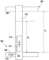
Turning now to FIG. 5, a schematic illustration of an overspeed safety system 500 is shown, according to an embodiment of the present disclosure. The overspeed safety system 500 can be similar to that shown and described above, and thus, a detailed description thereof can be omitted. The overspeed safety system 500 includes a safety brake 514, an electromechanical actuator 516, and a control system 518, the control system 518 communicating with the electromechanical actuator 516 via a communication line 524. Fig. 5 illustrates the positioning of the components of the overspeed safety system 500 relative to the car frame 504. The car frame 504 includes a platform 506, a ceiling 508, and a car structural member 510. As shown, in this embodiment, the control system 518 is mounted within the platform 506 of the car frame 504.
As shown, the safety brake 514 and the electromechanical actuator 516 are mounted such that these components are located below the ceiling 508 and above the platform 506 of the car frame 504, and they are mounted within and along the car structural component 510. The distance between the platform 506 and the ceiling 508 is defined as the car height HCAnd the safety brake 514 and the electromechanical actuator 516 are arranged at the car height HCAnd (4) the following steps. Specifically, in the exemplary embodiment, safety brake 514 and electromechanical actuator 516 are mounted at a lower mounting height HLInner and lower mounting height HLDefined as components along the car structure from the platform 506510, upward distance. In some embodiments, the lower mounting height HLMay be up to 2000 mm, but will have a distance sufficient to accommodate both the safety brake 514 and the electromechanical actuator 516 above the platform 506.
Lower mounting height HLA range of mounting positions of the safety brake 514 and the electromechanical actuator 516 may be defined such that inspection, repair, or other maintenance may be performed thereon. In some embodiments, when the safety brake 514 and the electromechanical actuator 516 are mounted at the lower mounting height HLMaintenance can be performed from an opening in a wall panel of the elevator car. It is noted that by positioning the safety brake 514 and the electromechanical actuator 516 within the car structural member 510 and at the car height HCThereby minimizing the height profile of the elevator car (i.e., components associated with the overspeed safety system 500 may not be located below the landing 506 of the car frame 504).
Advantageously, embodiments described herein provide an overspeed safety system as follows: safety braking can be provided to an elevator system while also minimizing the profile of such a system. For example, embodiments described herein may enable improved hoistway efficiency by minimizing the profile or extension of various components above and/or below the elevator car. Thus, embodiments described herein may enable the use of low pit depths and also low overhead distances within the elevator shaft.
The terminology used herein is for the purpose of describing particular embodiments only and is not intended to be limiting of the disclosure. The term "about" is intended to include a degree of error associated with measurement based on a particular quantity of equipment and/or manufacturing tolerances available at the time of filing this application. As used herein, the singular forms "a", "an" and "the" are intended to include the plural forms as well, unless the context clearly indicates otherwise. It will be further understood that the terms "comprises" and/or "comprising," when used in this specification, specify the presence of stated features, integers, steps, operations, elements, and/or components, but do not preclude the presence or addition of one or more other features, integers, steps, operations, elements, components, and/or groups thereof.
Those skilled in the art will recognize that various exemplary embodiments, each having certain features of the specific embodiments, are illustrated and described herein, but the disclosure is not so limited. Rather, the disclosure can be modified to incorporate any number of variations, alterations, permutations, combinations, sub-combinations, or equivalent arrangements not heretofore described, but which are commensurate with the scope of the disclosure. Additionally, while various embodiments of the disclosure have been described, it is to be understood that aspects of the disclosure may include only some of the described embodiments. Accordingly, the disclosure is not to be seen as limited by the foregoing description, but is only limited by the scope of the appended claims.
Claims (15)
1. An elevator system comprising:
an elevator car movable within a hoistway along a first guide rail and a second guide rail, the elevator car having a car frame including a platform, a ceiling, a first car structural member, and a second car structural member, wherein a distance between the platform and the ceiling is defined as a car height HC(ii) a And
an overspeed safety system, comprising:
a first safety brake and a first electromechanical actuator operably connected to the first safety brake, wherein the first safety brake and the first electromechanical actuator are at the car height HCPositioned internally within the first car structural member, and wherein the first safety brake is operable to engage the first guide rail to stop movement of the elevator car; and
a second safety brake and a second electromechanical actuator operatively connected to the second safety brake, wherein the second safety brake and the second electromechanical actuator are at the car height HCIs internally positioned within the second car structural member, and wherein the second safety brake is simultaneously operable with the first safety brake to engage the second guide rail to stop movement of the elevator car.
2. The elevator system of claim 1, wherein:
the first safety brake and the first electromechanical actuator are positioned within the first car structural component at respective upper mounting heights from the ceiling of the elevator car; and is
The second safety brake and the second electromechanical actuator are positioned within the second car structural member at respective upper mounting heights from the ceiling of the elevator car.
3. The elevator system of claim 2, wherein the upper mounting height of the first safety brake and the first electromechanical actuator is the same upper mounting height H as the upper mounting height of the second safety brake and the second electromechanical actuatorU。
4. The elevator system of claim 3, wherein the upper mounting height HUIs about 500 mm.
5. The elevator system of claim 1, wherein:
the first safety brake and the first electromechanical actuator are positioned within the first car structural member at respective lower mounting heights from the landing of the elevator car; and is
The second safety brake and the second electromechanical actuator are positioned within the second car structural member at respective lower mounting heights from the ceiling of the elevator car.
6. The elevator system of claim 5, wherein the lower mounting height of the first safety brake and the first electromechanical actuator is the same as the lower mounting height of the second safety brake and the second electromechanical actuatorThe height is the same lower mounting height HL。
7. The elevator system of claim 6, wherein the lower mounting height HLIs about 2000 mm.
8. The elevator system of any preceding claim, further comprising a control system operatively connected to the first electromechanical actuator and the second electromechanical actuator, the control system configured to activate the first electromechanical actuator and the second electromechanical actuator at least as a result of a detected overspeed event.
9. The elevator system of claim 8, wherein the control system is located on top of the ceiling of the elevator car.
10. The elevator system of claim 8, wherein the control system is located below the landing of the elevator car.
11. The elevator system of claim 8, wherein the control system is located within the ceiling of the elevator car.
12. The elevator system of claim 8, wherein the control system is located within the landing of the elevator car.
13. The elevator system of claim 8, wherein the control system is located within a cab of the elevator car.
14. The elevator system of any of claims 8-13, further comprising a communication line connecting the control system to the first electromechanical actuator and the second electromechanical actuator.
15. The elevator system of claim 14, wherein the communication line is at least one of a wired connection and a wireless connection.
Applications Claiming Priority (2)
| Application Number | Priority Date | Filing Date | Title |
|---|---|---|---|
| EP18306100.1A EP3608276A1 (en) | 2018-08-10 | 2018-08-10 | Elevator electrical safety actuator |
| EP18306100.1 | 2018-08-10 |
Publications (1)
| Publication Number | Publication Date |
|---|---|
| CN110817657A true CN110817657A (en) | 2020-02-21 |
Family
ID=63311945
Family Applications (1)
| Application Number | Title | Priority Date | Filing Date |
|---|---|---|---|
| CN201910735680.4A Pending CN110817657A (en) | 2018-08-10 | 2019-08-09 | Elevator electric safety actuator |
Country Status (3)
| Country | Link |
|---|---|
| US (1) | US20200048040A1 (en) |
| EP (1) | EP3608276A1 (en) |
| CN (1) | CN110817657A (en) |
Cited By (1)
| Publication number | Priority date | Publication date | Assignee | Title |
|---|---|---|---|---|
| CN114590680A (en) * | 2020-12-04 | 2022-06-07 | 奥的斯电梯公司 | Autonomous elevator car mover configured for preventing derailment |
Families Citing this family (4)
| Publication number | Priority date | Publication date | Assignee | Title |
|---|---|---|---|---|
| EP3459890B1 (en) * | 2017-09-20 | 2024-04-03 | Otis Elevator Company | Health monitoring of safety braking systems for elevators |
| US11691847B2 (en) * | 2019-06-20 | 2023-07-04 | Tk Elevator Corporation | Elevator travel blocking apparatus |
| AU2021442372A1 (en) * | 2021-04-28 | 2023-11-02 | Kone Corporation | Method for controlling elevator counterweight brake device and elevator |
| EP4330173A1 (en) * | 2021-04-28 | 2024-03-06 | KONE Corporation | Elevator |
Citations (10)
| Publication number | Priority date | Publication date | Assignee | Title |
|---|---|---|---|---|
| EP1748017A1 (en) * | 2004-05-20 | 2007-01-31 | Mitsubishi Denki Kabushiki Kaisha | Emergency stop device for elevator |
| CN101301976A (en) * | 2008-07-07 | 2008-11-12 | 西子奥的斯电梯有限公司 | Integrated security device of elevator |
| CN101535163A (en) * | 2006-11-08 | 2009-09-16 | 奥蒂斯电梯公司 | Elevator braking device |
| CN101920881A (en) * | 2009-06-11 | 2010-12-22 | 株式会社日立制作所 | Elevator with safety device |
| CN102514996A (en) * | 2011-12-30 | 2012-06-27 | 江南嘉捷电梯股份有限公司 | Elevator speed limiting device |
| CN205274964U (en) * | 2015-12-29 | 2016-06-01 | 西继迅达(许昌)电梯有限公司 | Upright post for elevator car |
| CN206126599U (en) * | 2016-10-18 | 2017-04-26 | 杭州奥立达电梯有限公司 | Steel band elevator car bottom structure |
| US20170240384A1 (en) * | 2016-02-23 | 2017-08-24 | Otis Elevator Company | Elevator service panel |
| US20170291798A1 (en) * | 2016-04-11 | 2017-10-12 | Otis Elevator Company | Electronic safety actuation device with a power assembly |
| CN107738972A (en) * | 2017-10-10 | 2018-02-27 | 美迪斯智能装备有限公司 | A kind of an ultra shallow pit elevator |
Family Cites Families (1)
| Publication number | Priority date | Publication date | Assignee | Title |
|---|---|---|---|---|
| MY167502A (en) * | 2010-12-17 | 2018-09-04 | Inventio Ag | Lift installation with car and counterweight |
-
2018
- 2018-08-10 EP EP18306100.1A patent/EP3608276A1/en not_active Withdrawn
-
2019
- 2019-08-02 US US16/530,365 patent/US20200048040A1/en not_active Abandoned
- 2019-08-09 CN CN201910735680.4A patent/CN110817657A/en active Pending
Patent Citations (10)
| Publication number | Priority date | Publication date | Assignee | Title |
|---|---|---|---|---|
| EP1748017A1 (en) * | 2004-05-20 | 2007-01-31 | Mitsubishi Denki Kabushiki Kaisha | Emergency stop device for elevator |
| CN101535163A (en) * | 2006-11-08 | 2009-09-16 | 奥蒂斯电梯公司 | Elevator braking device |
| CN101301976A (en) * | 2008-07-07 | 2008-11-12 | 西子奥的斯电梯有限公司 | Integrated security device of elevator |
| CN101920881A (en) * | 2009-06-11 | 2010-12-22 | 株式会社日立制作所 | Elevator with safety device |
| CN102514996A (en) * | 2011-12-30 | 2012-06-27 | 江南嘉捷电梯股份有限公司 | Elevator speed limiting device |
| CN205274964U (en) * | 2015-12-29 | 2016-06-01 | 西继迅达(许昌)电梯有限公司 | Upright post for elevator car |
| US20170240384A1 (en) * | 2016-02-23 | 2017-08-24 | Otis Elevator Company | Elevator service panel |
| US20170291798A1 (en) * | 2016-04-11 | 2017-10-12 | Otis Elevator Company | Electronic safety actuation device with a power assembly |
| CN206126599U (en) * | 2016-10-18 | 2017-04-26 | 杭州奥立达电梯有限公司 | Steel band elevator car bottom structure |
| CN107738972A (en) * | 2017-10-10 | 2018-02-27 | 美迪斯智能装备有限公司 | A kind of an ultra shallow pit elevator |
Non-Patent Citations (4)
| Title |
|---|
| 刘勇 等: "《电梯技术》", 31 January 2017, 北京理工大学出版社 * |
| 刘富海: "《智能电梯工程控制系统技术与应用》", 31 May 2017, 电子科技大学出版社 * |
| 李秧耕 等: "《电梯的使用与保养》", 30 September 1993, 中国劳动出版社 * |
| 陈家盛: "《电梯结构原理及安装维修》", 30 November 1992, 机械工业出版社 * |
Cited By (1)
| Publication number | Priority date | Publication date | Assignee | Title |
|---|---|---|---|---|
| CN114590680A (en) * | 2020-12-04 | 2022-06-07 | 奥的斯电梯公司 | Autonomous elevator car mover configured for preventing derailment |
Also Published As
| Publication number | Publication date |
|---|---|
| EP3608276A1 (en) | 2020-02-12 |
| US20200048040A1 (en) | 2020-02-13 |
Similar Documents
| Publication | Publication Date | Title |
|---|---|---|
| CN110817657A (en) | Elevator electric safety actuator | |
| EP3608275B1 (en) | Elevator electrical safety actuator controller | |
| EP3702310B1 (en) | Elevator safety with translating safety block | |
| CN107954297B (en) | Elevator car, elevator system and method for inspecting, maintaining and/or repairing an elevator system | |
| CN101896416B (en) | Lift system with lift cars which can move vertically and horizontally | |
| CN104684834B (en) | Low top or the indemnifying measure of low pit elevator | |
| CN103339052A (en) | Elevator arrangement and method | |
| CN110451382B (en) | Synchronization based on distance of magnet assembly to track | |
| CN110626917A (en) | Elevator system | |
| US11286132B2 (en) | Enhancing the transport capacity of an elevator system | |
| EP3666712B1 (en) | Elevator safety actuator systems | |
| CN102791605A (en) | Suspension body supporting device for elevator | |
| US11261056B2 (en) | Elevator safety actuator systems | |
| EP4039632A1 (en) | Method for expanding a rise of an elevator hoistway | |
| CN107531451A (en) | For ensuring the monitoring system for elevator device in predetermined lift well gap | |
| CN110654954B (en) | Electronic safety actuator electromagnetic guidance | |
| CN112850402A (en) | Emergency stop system for elevator | |
| KR102596311B1 (en) | Elevator system including a motorized module | |
| WO2023144918A1 (en) | Elevator | |
| JP2008019052A (en) | Terminal story forced deceleration device for elevator | |
| AU2020263967A1 (en) | A solution for overspeed monitoring of an elevator car | |
| JP2004203594A (en) | Elevator device |
Legal Events
| Date | Code | Title | Description |
|---|---|---|---|
| PB01 | Publication | ||
| PB01 | Publication | ||
| SE01 | Entry into force of request for substantive examination | ||
| SE01 | Entry into force of request for substantive examination | ||
| RJ01 | Rejection of invention patent application after publication | ||
| RJ01 | Rejection of invention patent application after publication |
Application publication date: 20200221 |