EP1747922A2 - Sliding window assembly for automotive vehicle - Google Patents
Sliding window assembly for automotive vehicle Download PDFInfo
- Publication number
- EP1747922A2 EP1747922A2 EP06118145A EP06118145A EP1747922A2 EP 1747922 A2 EP1747922 A2 EP 1747922A2 EP 06118145 A EP06118145 A EP 06118145A EP 06118145 A EP06118145 A EP 06118145A EP 1747922 A2 EP1747922 A2 EP 1747922A2
- Authority
- EP
- European Patent Office
- Prior art keywords
- sliding window
- frame plate
- window assembly
- assembly according
- functional elements
- Prior art date
- Legal status (The legal status is an assumption and is not a legal conclusion. Google has not performed a legal analysis and makes no representation as to the accuracy of the status listed.)
- Granted
Links
Images
Classifications
-
- B—PERFORMING OPERATIONS; TRANSPORTING
- B60—VEHICLES IN GENERAL
- B60J—WINDOWS, WINDSCREENS, NON-FIXED ROOFS, DOORS, OR SIMILAR DEVICES FOR VEHICLES; REMOVABLE EXTERNAL PROTECTIVE COVERINGS SPECIALLY ADAPTED FOR VEHICLES
- B60J1/00—Windows; Windscreens; Accessories therefor
- B60J1/08—Windows; Windscreens; Accessories therefor arranged at vehicle sides
- B60J1/12—Windows; Windscreens; Accessories therefor arranged at vehicle sides adjustable
- B60J1/16—Windows; Windscreens; Accessories therefor arranged at vehicle sides adjustable slidable
-
- B—PERFORMING OPERATIONS; TRANSPORTING
- B60—VEHICLES IN GENERAL
- B60J—WINDOWS, WINDSCREENS, NON-FIXED ROOFS, DOORS, OR SIMILAR DEVICES FOR VEHICLES; REMOVABLE EXTERNAL PROTECTIVE COVERINGS SPECIALLY ADAPTED FOR VEHICLES
- B60J10/00—Sealing arrangements
- B60J10/80—Sealing arrangements specially adapted for opening panels, e.g. doors
Definitions
- the invention relates to a sliding window assembly for a motor vehicle, wherein the sliding window assembly has at least one fixed surface element and at least one sliding window which is movable relative to the stationary surface element, the sliding window being flushly embedded in the surface element in the closed state to form a largely smooth and optically flat outer surface.
- the surface element is at least partially formed by a frame module, the frame module for forming the outer surface has a frame plate arranged on the outside, which is made at least on its outer side of a plastic material, and the inner side or edge of the frame plate functional elements are arranged.
- sliding window assemblies To create in motor vehicles in windows that are at least partially fixed to the body, for example side or roof windows to provide ventilation options for the interior, sliding window assemblies have been increasingly used nowadays.
- the movable sliding window releasing the opening of the window is arranged so flush in the stationary surface element of the sliding window, in the first instance, from an optical point of view, that in the closed state, a substantially flat, optically single-surface outer surface results.
- the EP 0 968 862 discloses a sliding window with a frame frame corresponding to the frame module.
- the frame together with a laterally arranged to this fixed glass sheet a recess into which a movable window is embedded.
- the frame may also be formed of plastic and also has on its inside to the inside welded or glued to this guide rails.
- the US 5,809,706 describes a sliding window assembly in which a fixed plate is used as a surface element flush with the body in a Karosserieausappelung.
- a fixed plate With the inside of the fixed plate functional elements are glued in the form of guide rails. Extensions of these guide rails can protrude into the edge region of the fixed plate and be glued between the body and the fixed plate to hold in case of an accident, the movable plate despite the bursting of the fixed plate in the guide rails can.
- the fixed plate if it is composed of several elements, can also be made of materials other than glass.
- the known sliding window assemblies bring a number of problems.
- the material properties of the glass are very advantageous in terms of transparency, hardness and scratch resistance, the brittleness, in particular in the case of an accident, entails risks and risks of injury that are difficult to calculate. Apart from that, glass is relatively heavy, which counteracts consistent lightweight construction. This has led - as can also be seen in the prior art - to partially manufacture the surface element of a plastic component.
- glass can be reasonably and durably connected only by gluing with other materials for the purpose relevant here.
- the necessary for a sliding window assembly further functional elements such as water drain, seals, guide rails, etc. are therefore glued in the prior art only indirectly or directly with the fixed surface element or body without the technical possibility of plastics processing consistently realize. In manufacturing this leads to further necessary manufacturing steps that make the end product more expensive.
- the shape is also much more difficult with glass.
- a design other than a disc-like or flat design of a glass component is difficult to achieve and often not be accepted for cost reasons. The same applies to the attachment of holes or threads in the glass or the integration of components in the glass, which does not allow the pouring of plastic components or seals due to its high processing temperatures.
- the object of the invention is therefore to simplify the design and manufacture of sliding window assemblies and cheaper to design. It should also be further advantages such as increased occupant safety in the event of a crash, weight reduction, space reduction, material savings or a visually appealing appearance can be achieved.
- Functional element and frame plate form a unit that is manufactured in a manufacturing step. It creates a compact assembly with a small space, which is not only due to the lighter weight in relation to glass plastic. Material savings also ensure a reduction in weight, since the bonding of separate functional elements to the frame plate generally requires more complex components, which are eliminated by the integration of the functional elements on or in the frame plate or constructive can be simplified.
- Another advantage is the occupant safety.
- the functional elements are formed directly on the inside of the frame plate and not merely glued, the sliding window assembly thus formed ensures increased security.
- suitable plastic which in contrast to glass anyway has a better impact resistance and a more favorable fracture behavior, the safety is further increased.
- the functional elements are not attached as an initially independent separate component after completion of the frame plate by gluing or welding to this. Rather, the functional elements are arranged within the manufacturing process of the frame plate at this or integrated into this, in which they cast, for example, at the same time with this as an integral component, at least partially poured within the frame plate, molded onto this or laminated together with this.
- the plastic material of the outside frame plate which is preferably a glass-mimicking plastic material, may be a PMMA or an ABS, for example.
- the decisive factor here is not that the plastic is transparent, since in motor vehicles, the conventional glass panes are also in its peripheral areas for the optical covering of splices or functional elements also regularly opaque. Rather, it is preferable to give only the visual impression that it is glass.
- the plastic can therefore also be through-dyed, painted or otherwise coated. In particular coatings come into consideration, which increase the resistance of the surface.
- the frame plate has on the outside a first material region, preferably of a glass-imitating plastic material, and on the inside has at least one second material region with different material properties to the first material region.
- the glass imitating plastic material of the outside of the frame plate has in relation to glass, although better impact resistance and better fracture properties, but still represents, for example, in the broad spectrum of plastics a rather brittle inelastic material.
- the frame plate preferably has the second material region on the inside. This can, as it does not have to meet the requirements of the outward facing surface, have other more suitable for the inside material properties.
- the second material region can in turn consist of different materials or materials.
- the frame plate of the frame module is at least partially made as a composite material or as a composite material.
- the frame plate combines the material properties of different materials and can be optimally designed according to the requirements.
- a composite material inter alia, a sandwich construction. With a suitable combination of materials, improved overall properties are achieved with regard to the entire frame plate.
- a configuration is advantageous in which the frame plate has a fiber-reinforced material region.
- This not only has the advantage of another Increasing the stability and the resistance to breakage, but also leads to the fact that the functional elements on the fibers, as long as they protrude as long fiber reinforcement in the glued to the body edge region of the frame plate, are also connected to the body. Even with a fracture of the frame plate, the functional elements are therefore not blasted in the event of a crash, but remain connected via the fibers to the body. This applies even more if the functional elements are laminated within the fiber layer. But it is also conceivable to use short fibers with which, for example, the plastic material of the frame plate are provided before an injection molding process.
- the desired compact sliding window assembly is achieved in particular by the fact that the functional elements are injection-molded on the inside or outside of the frame plate. They can be injected both directly and indirectly. Immediately means in this context that the functional elements are injection-molded directly in the same manufacturing step with the frame plate and thus formed on this. Indirect means that for the functional elements, a second, preferably takes place in the same tool injection molding process is initiated in order to provide for the functional elements optionally another suitable for their purpose material. Thus, both a one-component and a multi-component technique can be used. This can be achieved, for example, by drawing casting cores after the injection molding of the frame plate, in the space of which the material for the functional elements is then injected. If the frame plate has two material regions which are sprayed successively, the functional elements are preferably molded directly or indirectly onto the second material region.
- the functional elements may also be at least partially disposed within the frame plate and surrounded by the material of the frame plate, in particular be encapsulated by the material of the frame plate or laminated in this. Be about sealing strips or other functional elements such as support profiles encased in the frame plate, these are connected in a simpler and safer way with this. It is also possible to provide reinforcing inserts, in particular made of metal, which are encapsulated both by the frame plate material and by the material of a functional element. The connection between the frame plate and the functional element is thereby further increased. Such reinforcing inserts are in so far a separate molded directly on the frame plate or indirectly molded on this functional element.
- a reinforcing insert as a functional element may also be cast only partially in the frame plate, in particular in its second material region. This makes it possible to attach other components, which can not be formed directly or indirectly on the frame plate, for example because of their complexity, to the metal insert. As a result, further connection techniques such as screw or clip connections are possible, since the reinforcing insert can easily record resilient thread or snap hooks with suitable material. Gluing or welding can be dispensed with.
- the functional elements can serve a wide variety of purposes.
- the functional elements preferably comprise guide rails in which the sliding window is guided.
- a theft protection strip can be formed directly on the frame element, which makes it difficult to penetrate into the gap between sliding window and surface element with a tool or the impressions of the sliding window.
- water management that comprises means for draining the water, and drainage to derive to the outside.
- a water collecting channel be formed, which feeds the water provided in the frame plate drainage channels, which then turn outwards derived.
- the functional elements may further comprise means for displaying information, in particular illuminant displays, or sealing elements, in particular sealing strips. Also decorative strips may be provided which are integrated in the frame plate. These trims can also be arranged on the outside of the frame plate so that they are visible from the outside, for example, to make the transition from the body to the frame plate visually appealing. It is also conceivable to form on the frame plate means for holding additional elements such as blinds, fly screens, curtains, holding nets for small items, mirrors, reading lamps, cup holders, etc.
- the frame module itself is considered, which is not yet assembled into a sliding window assembly.
- the present invention need not be strictly limited to use with side sliding window assemblies. Also conceivable, for example, is the application in the area of a sunroof. Finally, the idea of the invention can also be applied to sliding window arrangements of other vehicles such as trains, ships and aircraft or also to the home area.
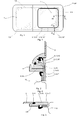
- FIG. 1 is a schematic overall view of a sliding window assembly
- Fig. 2 is a sectional view of a lower transition region of sliding window and frame module
- Fig. 3 is a sectional view of a lateral transition region of sliding window and frame module.
- a sliding window assembly is shown in the overall view.
- the sliding window assembly includes a fixed plate 1 having a glass plate arranged on the left side and a right side plate arranged frame module 3, in which a sliding window 2 is inserted.
- the sliding window assembly is exemplified such that the frame module 3 on the outside is flush with the left side arranged glass and the sliding window 2 is fully inserted in the closed state in the frame module 3.
- the fixed plate 1 is formed exclusively by the frame module 3.
- the frame module 3 which completely surrounds the sliding window 2 can alternatively be designed such that it surrounds the sliding window 2 only in the edge regions not facing the glass pane, so that the edge region of the sliding window 2 facing the glass pane directly adjoins the glass pane.
- the component forming the outer surface of the frame module 3 is formed by a frame plate 4 which here has a somewhat rectangular shape with rounded corners on one side and a recess for the sliding window 2. Overall, such a largely smooth and visually flat outer surface of the entire sliding window assembly is guaranteed. Smooth and visually just does not exclude the existence of construction-related gaps between the individual components forming the outer surface of course.
- this is displaced by the sliding mechanism from the outer surface plane of the sliding window unit inwardly and guided on the inside of the sliding window assembly along and substantially parallel to this.
- the opened position can be seen in the dashed line. If the glass pane arranged on the left side of the frame module 3 is dispensed with, as is the case, for example, in the case of a sunroof, the sliding window 2 is guided in a known manner behind the bodywork.
- Fig. 1 Some functional elements 5 are shown in dashed lines in Fig. 1.
- the frame module 3 on a theft protection strip 9, which surrounds the sliding window 2 back to the pressing or levering to complicate the sliding window.
- water channels 10 are also shown, through which liquid accumulating on the inside of the sliding window assembly can be discharged to the outside.
- Fig. 2 shows a sectional view of the lower portion of the sliding window assembly.
- the sliding window 2 is guided indirectly via a sliding block in a guide rail 8.
- the guide rail 8 is shown here by way of example not as a functional element, but rather attached to a formed by a metallic reinforcing insert 12 functional element 5,12, preferably clipped.
- the reinforcing insert is cast with a first region in a second material region 7 and thus formed directly on the frame plate 4.
- a second area forms the possibility of connection with the guide rail 8.
- the guide rail 8 can also be designed as a functional element and can be formed directly on the frame plate 4, even with or without a reinforcing insert 12.
- the frame plate 4 further comprises a water management system, in which below a sealing lip, which seals the gap between the sliding window 2 and the frame module 3 inwardly, a collecting channel 10 'is arranged. This is formed directly on the second material portion 7 of the frame plate 4 and integrally connected thereto.
- a water management system in which below a sealing lip, which seals the gap between the sliding window 2 and the frame module 3 inwardly, a collecting channel 10 'is arranged. This is formed directly on the second material portion 7 of the frame plate 4 and integrally connected thereto.
- three drainage channels 10 are provided within the frame plate 4, which divert the water collected in the collecting groove 10 'through the frame plate 4 to the outside.
- the frame plate 4 has in Fig. 2 in addition to a first material region 6 on a second material region.
- the first material region 6 in FIG. 3 is significantly narrower than that in FIG. 2.
- Of importance is the realization that one can achieve a material composite with an outer first material region 6 and an inner second material region 7, which meet the different requirements for the vehicle outside and on the inner side of the frame plate can.
- the sectional view of the lateral transition region of the sliding window 2 and the frame module 3 in FIG. 3 shows, as further functional elements 5, a theft protection strip 9 and a seal 11 cast into the frame plate 4 and thus formed directly on it.
- the theft protection strip 9 is integrally connected to the frame plate 4 and thus forms with this a particularly stable unit. The usual bonding of such a bar is omitted.
- the frame module 3 in FIG. 2 and FIG. 3 is permanently connected to the vehicle body 12 via an adhesive seam.
- the frame plate 4 may, of course, be composed of a plurality of sub-panels that are assembled and each form part of the outer surface of the sliding window assembly.
Abstract
Description
Die Erfindung betrifft eine Schiebefensterbaugruppe für ein Kraftfahrzeug, wobei die Schiebefensterbaugruppe zumindest ein feststehendes Flächenelement und zumindest ein relativ zum feststehenden Flächenelement bewegliches Schiebefenster aufweist, - das Schiebefenster im geschlossenen Zustand außenseitig bündig in dem Flächenelement unter Bildung einer weitestgehend glatten und optisch ebenen Außenfläche eingelassen ist, das Flächenelement zumindest zum Teil von einem Rahmenmodul gebildet ist, das Rahmenmodul zur Bildung der Außenfläche eine außenseitig angeordnete Rahmenplatte aufweist, die zumindest an ihrer Außenseite aus einem Kunststoffmaterial hergestellt ist, und innenseitig oder randseitig an der Rahmenplatte Funktionselemente angeordnet sind.The invention relates to a sliding window assembly for a motor vehicle, wherein the sliding window assembly has at least one fixed surface element and at least one sliding window which is movable relative to the stationary surface element, the sliding window being flushly embedded in the surface element in the closed state to form a largely smooth and optically flat outer surface. the surface element is at least partially formed by a frame module, the frame module for forming the outer surface has a frame plate arranged on the outside, which is made at least on its outer side of a plastic material, and the inner side or edge of the frame plate functional elements are arranged.
Um bei Kraftfahrzeugen auch in Fenstern, die zumindest in Teilen ortsfest zur Karosserie angeordnet sind, beispielsweise Seiten- oder Dachfenster, Lüftungsmöglichkeiten für den Innenraum zu schaffen, sind in letzter Zeit zunehmend Schiebefensteranordnungen eingesetzt worden. Dabei ist in erster Linie aus optischen Gesichtspunkten das bewegliche, die Öffnung des Fensters freigebende Schiebefenster derart bündig im feststehenden Flächenelement des Schiebefensters angeordnet, dass sich im geschlossenen Zustand eine im wesentlichen ebene, optisch einflächige Außenfläche ergibt.To create in motor vehicles in windows that are at least partially fixed to the body, for example side or roof windows to provide ventilation options for the interior, sliding window assemblies have been increasingly used lately. In this case, the movable sliding window releasing the opening of the window is arranged so flush in the stationary surface element of the sliding window, in the first instance, from an optical point of view, that in the closed state, a substantially flat, optically single-surface outer surface results.
Rahmenmodule für Schiebefensteranordnungen dieser Art sind bekannt. Die
Die
Die bekannten Schiebefensterbaugruppen bringen jedoch eine Reihe von Problemen mit sich. Zum einen ist die Verwendung von Glas problematisch. Dessen Herstellung und Ver- bzw. Bearbeitung ist relativ teuer. Lochartige Ausnehmungen in Glasplatten einzubringen ist fertigungstechnisch schwierig und daher kostspielig. Geforderte Toleranzen und die gewünschte Glasqualität können regelmäßig nur schwer eingehalten werden. Ferner sind die Materialeigenschaften des Glases zwar hinsichtlich der Durchsichtigkeit, Härte und Kratzfestigkeit sehr vorteilhaft, jedoch birgt die Brüchigkeit insbesondere bei einem Unfall schwer zu kalkulierende Risiken und Verletzungsgefahren. Hiervon abgesehen ist Glas relativ schwer, was einem konsequenten Leichtbau entgegenwirkt. Dies hat dazu geführt - wie auch dem Stand der Technik zu entnehmen ist - das Flächenelement teilweise aus einem Kunststoffbauteil zu fertigen.The known sliding window assemblies, however, bring a number of problems. First, the use of glass is problematic. Its production and processing is relatively expensive. To introduce hole-like recesses in glass plates is difficult to manufacture and therefore expensive. Demanded tolerances and the desired glass quality can be maintained only with difficulty. Furthermore, although the material properties of the glass are very advantageous in terms of transparency, hardness and scratch resistance, the brittleness, in particular in the case of an accident, entails risks and risks of injury that are difficult to calculate. Apart from that, glass is relatively heavy, which counteracts consistent lightweight construction. This has led - as can also be seen in the prior art - to partially manufacture the surface element of a plastic component.
Glas lässt sich ferner für den hier relevanten Zweck sinnvoll nur durch Kleben mit anderen Materialien dauerhaft und sicher verbinden. Die für eine Schiebefensterbaugruppe notwendigen weiteren Funktionselemente wie Wasserablauf, Dichtungen, Führungsschienen etc. werden daher im Stand der Technik ausschließlich mittelbar oder unmittelbar mit dem feststehenden Flächenelement oder der Karosserie verklebt, ohne dabei die technischen Möglichkeit der Kunststoffverarbeitung konsequent zu verwirklichen. Dies führt in der Fertigung zu weiteren notwendigen Fertigungsschritten, die das Endprodukt verteuern. Auch die Formgebung ist bei Glas deutlich schwieriger. Eine andere Gestaltung als eine scheibenartige bzw. flächige Gestaltung eines Glasbauteils ist schwierig zu erzielen und aus Kostengründen oft nicht zu akzeptieren. Gleiches gilt für das Anbringen von Bohrungen oder Gewinden im Glas oder die Integration von Bauteilen im Glas, das durch dessen hohe Verarbeitungstemperaturen beispielsweise das Eingießen von Kunststoffbauteilen oder Dichtungen nicht erlaubt.Furthermore, glass can be reasonably and durably connected only by gluing with other materials for the purpose relevant here. The necessary for a sliding window assembly further functional elements such as water drain, seals, guide rails, etc. are therefore glued in the prior art only indirectly or directly with the fixed surface element or body without the technical possibility of plastics processing consistently realize. In manufacturing this leads to further necessary manufacturing steps that make the end product more expensive. The shape is also much more difficult with glass. A design other than a disc-like or flat design of a glass component is difficult to achieve and often not be accepted for cost reasons. The same applies to the attachment of holes or threads in the glass or the integration of components in the glass, which does not allow the pouring of plastic components or seals due to its high processing temperatures.
Aufgabe der Erfindung ist es daher, die Konstruktion und die Fertigung von Schiebefensterbaugruppen zu vereinfachen und kostengünstiger zu gestalten. Es sollen ferner weitere Vorteile wie erhöhte Insassensicherheit im Crashfall, Gewichtsreduzierung, Bauraumverringerung, Materialeinsparungen oder auch eine optische ansprechendere Erscheinung erzielt werden.The object of the invention is therefore to simplify the design and manufacture of sliding window assemblies and cheaper to design. It should also be further advantages such as increased occupant safety in the event of a crash, weight reduction, space reduction, material savings or a visually appealing appearance can be achieved.
Diese Aufgabe wird nach der Erfindung dadurch gelöst, dass das Funktionselement unmittelbar an und/oder in der Rahmenplatte angeformt ist.This object is achieved according to the invention in that the functional element is formed directly on and / or in the frame plate.
Es ist somit möglich, auf ein Ankleben oder Anschweißen eines getrennt zu fertigenden Funktionselementes zumindest an dem Teil des Flächenelements, das aus Kunststoff hergestellt ist, zu verzichten. Funktionselement und Rahmenplatte bilden eine Einheit, die in einem Fertigungsschritt hergestellt wird. Es wird eine kompakte Baugruppe mit geringem Bauraum geschaffen, die nicht nur aufgrund des im Verhältnis zu Glas leichteren Kunststoffs gewichtsreduziert ist. Auch Materialeinsparungen gewährleisten eine Gewichtsreduktion, da das Verkleben getrennter Funktionselemente an die Rahmenplatte in der Regel aufwendigere Bauteile erfordert, die durch die Integration der Funktionselemente an bzw. in die Rahmenplatte entfallen oder konstruktiv vereinfacht können.It is thus possible to dispense with gluing or welding on a functional element to be produced separately at least on the part of the surface element which is made of plastic. Functional element and frame plate form a unit that is manufactured in a manufacturing step. It creates a compact assembly with a small space, which is not only due to the lighter weight in relation to glass plastic. Material savings also ensure a reduction in weight, since the bonding of separate functional elements to the frame plate generally requires more complex components, which are eliminated by the integration of the functional elements on or in the frame plate or constructive can be simplified.
Ein weiterer Vorteil ist die Insassensicherheit. Bei der Verwendung von Glas bzw. bei dem Verkleben oder Verschweißen der Funktionselemente mit der Rahmenplatte besteht möglicherweise die Gefahr, dass sich einzelne Teile im Falle von Extremkräften von der Rahmenplatte lösen, in den Innenraum geschleudert werden und Insassen verletzen. Sind die Funktionselemente jedoch unmittelbar an die Innenseite der Rahmenplatte angeformt und nicht lediglich angeklebt, gewährleistet die so gebildete Schiebefensterbaugruppe eine erhöhte Sicherheit. Hinzu kommt, dass durch die konsequente Verwendung von geeignetem Kunststoff, der im Gegensatz zu Glas ohnehin eine bessere Schlagzähigkeit und ein günstigeres Bruchverhalten aufweist, die Sicherheit weiter erhöht wird.Another advantage is the occupant safety. When using glass or when gluing or welding the functional elements to the frame plate, there is a risk that individual parts will be released from the frame plate in the case of extreme forces, thrown into the interior and injure occupants. However, the functional elements are formed directly on the inside of the frame plate and not merely glued, the sliding window assembly thus formed ensures increased security. In addition, through the consistent use of suitable plastic, which in contrast to glass anyway has a better impact resistance and a more favorable fracture behavior, the safety is further increased.
Unmittelbar an der Rahmenplatte anformen bedeutet in diesem Zusammenhang, dass die Funktionselemente nicht als zunächst eigenständiges getrenntes Bauteil nach Fertigstellung der Rahmenplatte durch Kleben oder Anschweißen an dieser angebracht werden. Vielmehr sollen die Funktionselemente innerhalb des Fertigungsprozesses der Rahmenplatte an dieser angeordnet bzw. in diese integriert werden, in dem sie beispielsweise gleichzeitig mit dieser als integrales Bauteil gegossen, zumindest teilweise innerhalb der Rahmenplatte eingegossen, an diese angespritzt oder etwa mit dieser zusammenlaminiert werden.Immediately molding on the frame plate means in this context that the functional elements are not attached as an initially independent separate component after completion of the frame plate by gluing or welding to this. Rather, the functional elements are arranged within the manufacturing process of the frame plate at this or integrated into this, in which they cast, for example, at the same time with this as an integral component, at least partially poured within the frame plate, molded onto this or laminated together with this.
Das Kunststoffmaterial der außenseitigen Rahmenplatte, das vorzugsweise ein Glas imitierendes Kunststoffmaterial ist, kann dabei beispielsweise ein PMMA oder ein ABS sein. Entscheidend ist dabei nicht, dass der Kunststoff durchsichtig ist, da bei Kraftfahrzeugen die herkömmlichen Glasscheiben in ihren Randbereichen zum optischen Verdecken von Klebestellen oder von Funktionselementen ebenfalls regelmäßig undurchsichtig sind. Vielmehr soll bevorzugt lediglich der optische Eindruck erweckt werden, dass es sich um Glas handele. Der Kunststoff kann also etwa auch durchgefärbt, lackiert oder anderweitig beschichtet sein. Dabei kommen insbesondere Beschichtungen in Betracht, die die Widerstandsfähigkeit der Oberfläche erhöhen.The plastic material of the outside frame plate, which is preferably a glass-mimicking plastic material, may be a PMMA or an ABS, for example. The decisive factor here is not that the plastic is transparent, since in motor vehicles, the conventional glass panes are also in its peripheral areas for the optical covering of splices or functional elements also regularly opaque. Rather, it is preferable to give only the visual impression that it is glass. The plastic can therefore also be through-dyed, painted or otherwise coated. In particular coatings come into consideration, which increase the resistance of the surface.
Um die Insassensicherheit weiter zu erhöhen, kann vorgesehen sein, dass die Rahmenplatte außenseitig einen ersten Materialbereich, vorzugsweise aus einem Glas imitierenden Kunststoffmaterial, und innenseitig zumindest einen zweiten Materialbereich mit zum ersten Materialbereich unterschiedlichen Werkstoffeigenschaften aufweist. Das Glas imitierende Kunststoffmaterial der Außenseite der Rahmenplatte weist im Verhältnis zu Glas zwar eine bessere Schlagzähigkeit und günstigere Brucheigenschaften auf, stellt aber beispielsweise im breiten Spektrum der Kunststoffe immer noch einen eher brüchiges unelastisches Material dar. Um die Rahmenplatte weiter zu optimieren und auch das Anformen der Funktionselemente zu erleichtern, weist daher die Rahmenplatte bevorzugt innenseitig den zweiten Materialbereich auf. Dieser kann, da er nicht die Anforderungen der nach außen gerichteten Fläche erfüllen muss, andere, für die Innenseite geeignetere Materialeigenschaften aufweisen. Dies kann dadurch erreicht werden, dass beim Spritzgießen der Rahmenplatte die Materialeigenschaften der Außen- bzw. Innenseite durch unterschiedliche Abkühlkurven unterschiedlich beeinflusst werden. Es kann auch vorgesehen werden, dass erst nach Spritzgießen des ersten Materialbereichs das Werkzeug den Raum für den zweiten Materialbereich freigibt, so dass dieser nachgespritzt wird. Bei einer geeigneten Beschichtung der Außenseite kann auch die Beschichtung selbst den ersten Materialbereich bilden. Der zweite Materialbereich kann in sich wiederum aus unterschiedlichen Materialien bzw. Werkstoffen bestehen.In order to further increase occupant safety, it may be provided that the frame plate has on the outside a first material region, preferably of a glass-imitating plastic material, and on the inside has at least one second material region with different material properties to the first material region. The glass imitating plastic material of the outside of the frame plate has in relation to glass, although better impact resistance and better fracture properties, but still represents, for example, in the broad spectrum of plastics a rather brittle inelastic material. To further optimize the frame plate and the molding of the Therefore, to facilitate functional elements, the frame plate preferably has the second material region on the inside. This can, as it does not have to meet the requirements of the outward facing surface, have other more suitable for the inside material properties. This can be achieved by the material properties of the outer or inner side being differently influenced by different cooling curves during injection molding of the frame plate. It can also be provided that only after injection molding of the first material region, the tool releases the space for the second material region, so that it is nachgespritzt. With a suitable coating on the outside, the coating itself can also form the first material region. The second material region can in turn consist of different materials or materials.
Eine alternative Ausgestaltung sieht vor, dass die Rahmenplatte des Rahmenmoduls zumindest zum Teil als Werkstoffverbund oder als Verbundwerkstoff hergestellt ist. Dies führt dazu, dass die Rahmenplatte die Werkstoffeigenschaften verschiedener Materialien in sich vereint den Anforderungen entsprechend optimal ausgelegt werden kann. Hierzu bietet sich als Materialverbund unter anderem eine Sandwichbauweise. Bei einer geeigneten Materialkombination ergeben sich im Hinblick auf die gesamte Rahmenplatte verbesserte Gesamteigenschaften.An alternative embodiment provides that the frame plate of the frame module is at least partially made as a composite material or as a composite material. As a result, the frame plate combines the material properties of different materials and can be optimally designed according to the requirements. For this purpose, as a composite material, inter alia, a sandwich construction. With a suitable combination of materials, improved overall properties are achieved with regard to the entire frame plate.
Um die Sicherheit und die Bruchfestigkeit weiter zu erhöhen, ist eine Ausgestaltung vorteilhaft, bei der die Rahmenplatte einen faserverstärkten Materialbereich aufweist. Dies hat nicht nur den Vorteil einer weiteren Erhöhung der Stabilität und der Bruchsicherheit, sondern führt auch dazu, dass die Funktionselemente über die Fasern, sofern diese als Langfaserverstärkung in den mit der Karosserie verklebten Randbereich der Rahmenplatte ragen, ebenfalls mit der Karosserie verbunden sind. Selbst bei einem Bruch der Rahmenplatte werden die Funktionselemente im Crashfall daher nicht abgesprengt, sondern bleiben über die Fasern mit der Karosserie verbunden. Dies gilt um so mehr, falls die Funktionselemente innerhalb der Faserschicht einlaminiert sind. Es ist aber auch die Verwendung von Kurzfasern denkbar, mit denen beispielsweise das Kunststoffmaterial der Rahmenplatte vor einem Spritzgussprozess versehen sind.In order to further increase the safety and the breaking strength, a configuration is advantageous in which the frame plate has a fiber-reinforced material region. This not only has the advantage of another Increasing the stability and the resistance to breakage, but also leads to the fact that the functional elements on the fibers, as long as they protrude as long fiber reinforcement in the glued to the body edge region of the frame plate, are also connected to the body. Even with a fracture of the frame plate, the functional elements are therefore not blasted in the event of a crash, but remain connected via the fibers to the body. This applies even more if the functional elements are laminated within the fiber layer. But it is also conceivable to use short fibers with which, for example, the plastic material of the frame plate are provided before an injection molding process.
Die gewünschte kompakte Schiebefensterbaugruppe wird insbesondere dadurch erzielt, dass die Funktionselemente an der Rahmenplatte innenseitig oder randseitig angespritzt sind. Sie können dabei sowohl unmittelbar als auch mittelbar angespritzt werden. Unmittelbar heißt in diesem Zusammenhang, dass die Funktionselemente direkt im selben Fertigungsschritt mit der Rahmenplatte spritzgegossen und so an dieser angeformt werden. Mittelbar bedeutet, dass für die Funktionselemente ein zweiter, vorzugsweise im gleichen Werkzeug stattfindender Spritzgussprozess initiiert wird, um für die Funktionselemente gegebenenfalls ein anderes für ihren Zweck geeigneteres Material vorzusehen. Es kann also sowohl eine Einkomponenten- als auch eine Mehrkomponententechnik angewandt werden. Dies kann beispielsweise dadurch erreicht werden, dass nach dem Spritzgießen der Rahmenplatte Gusskerne gezogen werden, in deren Raum dann das Material für die Funktionselemente gespritzt wird. Sofern die Rahmenplatte zwei Materialbereiche aufweist, die nacheinander gespritzt werden, so werden die Funktionselemente vorzugsweise an den zweiten Materialbereich unmittelbar oder mittelbar angespritzt.The desired compact sliding window assembly is achieved in particular by the fact that the functional elements are injection-molded on the inside or outside of the frame plate. They can be injected both directly and indirectly. Immediately means in this context that the functional elements are injection-molded directly in the same manufacturing step with the frame plate and thus formed on this. Indirect means that for the functional elements, a second, preferably takes place in the same tool injection molding process is initiated in order to provide for the functional elements optionally another suitable for their purpose material. Thus, both a one-component and a multi-component technique can be used. This can be achieved, for example, by drawing casting cores after the injection molding of the frame plate, in the space of which the material for the functional elements is then injected. If the frame plate has two material regions which are sprayed successively, the functional elements are preferably molded directly or indirectly onto the second material region.
Die Funktionselemente können auch zumindest teilweise innerhalb der Rahmenplatte angeordnet und von dem Material der Rahmenplatte umgeben sein, insbesondere von dem Material der Rahmenplatte umspritzt oder in diese einlaminiert sein. Werden etwa Dichtungsleisten oder andere Funktionselemente wie Stützprofile von der Rahmenplatte umgossen, sind diese auf einfachere und sicherere Weise mit dieser verbunden. Auch können Verstärkungseinlagen, insbesondere aus Metall, vorgesehen sein, die sowohl von dem Rahmenplattenmaterial als auch vom Material eines Funktionselement umgossen sind. Die Verbindung von Rahmenplatte und Funktionselement wird dadurch weiter erhöht. Solche Verstärkungseinlagen stellen in so fern ein eigenes unmittelbar an der Rahmenplatte angeformtes bzw. mittelbar an dieser angespritztes Funktionselement dar.The functional elements may also be at least partially disposed within the frame plate and surrounded by the material of the frame plate, in particular be encapsulated by the material of the frame plate or laminated in this. Be about sealing strips or other functional elements such as support profiles encased in the frame plate, these are connected in a simpler and safer way with this. It is also possible to provide reinforcing inserts, in particular made of metal, which are encapsulated both by the frame plate material and by the material of a functional element. The connection between the frame plate and the functional element is thereby further increased. Such reinforcing inserts are in so far a separate molded directly on the frame plate or indirectly molded on this functional element.
Eine Verstärkungseinlage als Funktionselement, insbesondere eine Metalleinlage, kann auch nur teilweise in der Rahmenplatte, insbesondere in deren zweiten Materialbereich, eingegossen sein. Dies ermöglicht es, weitere Bauteile, die beispielsweise aufgrund ihrer Komplexität nicht mittelbar oder unmittelbar an die Rahmenplatte angeformt werden können oder sollen, an die Metalleinlage anzustecken. Hierdurch werden weitere Verbindungstechniken wie Schraub- oder Klipsverbindungen ermöglicht, da die verstärkende Einlage bei geeignetem Material ohne weiteres belastbare Gewinde oder Schnapphaken aufnehmen kann. Auf ein Kleben oder Anschweißen kann verzichtet werden.A reinforcing insert as a functional element, in particular a metal insert, may also be cast only partially in the frame plate, in particular in its second material region. This makes it possible to attach other components, which can not be formed directly or indirectly on the frame plate, for example because of their complexity, to the metal insert. As a result, further connection techniques such as screw or clip connections are possible, since the reinforcing insert can easily record resilient thread or snap hooks with suitable material. Gluing or welding can be dispensed with.
Funktionselemente können dabei unterschiedlichsten Zwecken dienen. So umfassen bevorzugt die Funktionselemente Führungsschienen, in denen das Schiebfenster geführt ist. Auch kann unmittelbar an das Rahmenelement eine Diebstahlschutzleiste angeformt werden, die das Eindringen in den Spalt zwischen Schiebefenster und Flächenelement mit einem Werkzeug oder das Eindrücken des Schiebefensters erschwert. Ferner bietet es sich an, an der Innenseite der Scheibe anfallendes Wasser, beispielsweise Kondens- bzw. Schwitzwasser oder von außen aufgrund von Undichtigkeiten durch die Dichtungen eindringendes Wasser, durch ein Wassermanagement, dass Mittel zum Ableiten des Wassers umfasst, zu sammeln und über einen Wasserablauf nach außen abzuleiten. So kann beispielsweise an das Rahmenelement eine Wasserauffangrinne angeformt sein, die das Wasser in der Rahmenplatte vorgesehenen Ablaufkanälen zuleitet, die es dann wiederum nach außen ableiten. Die Funktionselemente können ferner Mittel zum Anzeigen von Informationen, insbesondere Leuchtmittelanzeigen, oder Dichtelemente, insbesondere Dichtleisten, umfassen. Auch können Zierleisten vorgesehen sein, die in die Rahmenplatte integriert sind. Diese Zierleisten können auch außenseitig derart an der Rahmenplatte angeordnet sein, dass sie von außen sichtbar sind, beispielsweise um den Übergang von Karosserie zur Rahmenplatte optisch ansprechend zu gestalten. Auch ist es denkbar, an die Rahmenplatte Mittel zum Halten von Zusatzelementen wie Jalousien, Fliegengitter, Gardinen, Haltenetze für Kleingegenstände, Spiegel, Leselampen, Getränkehalter etc. anzuformen.Functional elements can serve a wide variety of purposes. Thus, the functional elements preferably comprise guide rails in which the sliding window is guided. Also, a theft protection strip can be formed directly on the frame element, which makes it difficult to penetrate into the gap between sliding window and surface element with a tool or the impressions of the sliding window. Furthermore, it is advisable to collect water accumulating on the inside of the pane, for example condensation or condensation water, or water entering from outside due to leaks through the seals, water management that comprises means for draining the water, and drainage to derive to the outside. Thus, for example, to the frame element, a water collecting channel be formed, which feeds the water provided in the frame plate drainage channels, which then turn outwards derived. The functional elements may further comprise means for displaying information, in particular illuminant displays, or sealing elements, in particular sealing strips. Also decorative strips may be provided which are integrated in the frame plate. These trims can also be arranged on the outside of the frame plate so that they are visible from the outside, for example, to make the transition from the body to the frame plate visually appealing. It is also conceivable to form on the frame plate means for holding additional elements such as blinds, fly screens, curtains, holding nets for small items, mirrors, reading lamps, cup holders, etc.
Ebenfalls zur Erfindung gehörig wird das Rahmenmodul selbst angesehen, das noch nicht zu einer Schiebefensterbaugruppe zusammengesetzt ist. Ferner sei erwähnt, dass die vorliegende Erfindung selbstverständlich nicht strikt auf die Anwendung bei seitlichen Schiebefensterbaugruppen beschränkt sein muss. Ebenfalls denkbar ist beispielsweise die Anwendung im Bereich eines Schiebedachs. Letztlich lässt sich der Erfindungsgedanke auch auf Schiebefensteranordnungen von anderen Fahrzeugen wie Züge, Schiffe und Flugzeuge oder auch auf den Heimbereich anwenden.Also belonging to the invention, the frame module itself is considered, which is not yet assembled into a sliding window assembly. It should also be noted that, of course, the present invention need not be strictly limited to use with side sliding window assemblies. Also conceivable, for example, is the application in the area of a sunroof. Finally, the idea of the invention can also be applied to sliding window arrangements of other vehicles such as trains, ships and aircraft or also to the home area.
Weitere Merkmale und Vorteile der Erfindung ergeben sich aus den Unteransprüchen und aus der nachfolgenden Beschreibung bevorzugter Ausführungsbeispiele anhand der Zeichnungen.Further features and advantages of the invention will become apparent from the subclaims and from the following description of preferred embodiments with reference to the drawings.
In den Zeichnungen zeigt:In the drawings shows:
Fig. 1 eine schematische Gesamtansicht einer Schiebefensterbaugruppe,1 is a schematic overall view of a sliding window assembly,
Fig. 2 eine Schnittansicht eines unteren Übergangsbereichs von Schiebefenster und Rahmenmodul, undFig. 2 is a sectional view of a lower transition region of sliding window and frame module, and
Fig. 3 eine Schnittansicht eines seitlichen Übergangsbereichs von Schiebefenster und Rahmenmodul.Fig. 3 is a sectional view of a lateral transition region of sliding window and frame module.
In Fig. 1 ist eine Schiebefensterbaugruppe in der Gesamtansicht dargestellt. Die Schiebefensterbaugruppe umfasst eine feststehende Platte 1, die eine linksseitig angeordnete Glasscheibe und ein rechtsseitig angeordnetes Rahmenmodul 3 aufweist, in das ein Schiebefenster 2 eingelassen ist. In Fig. 1 ist die Schiebefensterbaugruppe beispielhaft derart dargestellt, dass das Rahmenmodul 3 außenseitig bündig mit der linksseitig angeordneten Glasscheibe abschließt und das Schiebefenster 2 im geschlossenen Zustand vollumfänglich in das Rahmenmodul 3 eingelassen ist. Alternativ kann selbstverständlich auch auf die linksseitig angeordnete Glasscheibe verzichtet werden, so dass die feststehende Platte 1 ausschließlich von dem Rahmenmodul 3 gebildet ist. Auch das das Schiebefenster 2 vollumfänglich umgebende Rahmenmodul 3 kann alternativ so ausgestaltet sein, dass es das Schiebefenster 2 nur in den nicht der Glasscheibe zugewandten Randbereichen umgibt, so dass der der Glasscheibe zugewandte Randbereich des Schiebefensters 2 unmittelbar an die Glasscheibe angrenzt.In Fig. 1, a sliding window assembly is shown in the overall view. The sliding window assembly includes a fixed
Der die Außenfläche des Rahmenmoduls 3 bildende Bestandteil ist von einer Rahmenplatte 4 gebildet, die hier etwas rechteckförmig mit an einer Seite abgerundeten Ecken und eine Ausnehmung für das Schiebefenster 2 aufweist. Insgesamt ist so eine weitestgehend glatte und optisch ebene Außenfläche der gesamten Schiebefensterbaugruppe gewährleistet. Glatt und optisch eben schließt selbstverständlich das Vorhandensein konstruktionsbedingter Spalte zwischen den einzelnen die Außenfläche bildenden Bauteilen nicht aus.The component forming the outer surface of the frame module 3 is formed by a frame plate 4 which here has a somewhat rectangular shape with rounded corners on one side and a recess for the sliding
Zum Verschieben des Schiebefensters 2 wird dieses durch den Verschiebemechanismus aus der Außenflächenebene der Schiebefenstereinheit nach innen hin verschoben und auf der Innenseite der Schiebefensterbaugruppe entlang und im wesentlichen parallel zu dieser geführt. Die geöffnete Position ist der gestrichelten Darstellung zu entnehmen. Wird auf die linksseitig zum Rahmenmodul 3 angeordnete Glasscheibe verzichtet, wie es sich beispielsweise bei einem Schiebedach anbietet, wird das Schiebefenster 2 in bekannter Weise hinter der Karosserie geführt.To move the sliding
Einige Funktionselemente 5 sind in Fig. 1 gestrichelt dargestellt. So weist das Rahmenmodul 3 eine Diebstahlschutzleiste 9 auf, die das Schiebefenster 2 rückseitig umgreift, um das Eindrücken oder Aushebeln des Schiebefensters zu erschweren. Ferner sind neben einer oberen und einer unteren Führungsschiene 8 auch Wasserkanäle 10" gezeigt, durch die hindurch auf der Innenseite der Schiebefensterbaugruppe anfallende Flüssigkeit nach außen abgeleitet werden kann.Some functional elements 5 are shown in dashed lines in Fig. 1. Thus, the frame module 3 on a theft protection strip 9, which surrounds the sliding
Fig. 2 zeigt eine Schnittansicht des unteren Bereichs der Schiebefensterbaugruppe. Das Schiebefenster 2 ist mittelbar über einen Gleitschuh in einer Führungsschiene 8 geführt. Die Führungsschiene 8 ist hier beispielhaft nicht als Funktionselement gezeigt, sonder vielmehr auf ein durch eine metallische Verstärkungseinlage 12 gebildetes Funktionselement 5,12 aufgesteckt, vorzugsweise aufgeklipst. Die Verstärkungseinlage ist mit einem ersten Bereich in einen zweiten Materialbereich 7 eingegossen und so unmittelbar an der Rahmenplatte 4 angeformt. Ein zweiter Bereich bildet die Verbindungsmöglichkeit mit der Führungsschiene 8. Die Führungsschiene 8 kann aber in einer anderen Ausgestaltung auch als Funktionselement ausgestaltet und selbst mit oder ohne Verstärkungseinlage 12 unmittelbar an die Rahmenplatte 4 angeformt sein.Fig. 2 shows a sectional view of the lower portion of the sliding window assembly. The sliding
Die Rahmenplatte 4 weist weiter ein Wassermanagementsystem auf, bei dem unterhalb einer Dichtlippe, die den Spalt zwischen Schiebefenster 2 und Rahmenmodul 3 nach innen abdichtet, eine Auffangrinne 10' angeordnet ist. Diese ist unmittelbar an den zweiten Materialbereich 7 der Rahmenplatte 4 angeformt und mit diesem einstückig verbunden. Gleichzeitig ist sind bei der in Fig. 1 dargestellten Schiebefensterbaugruppe drei Ablaufkanäle 10" innerhalb der Rahmenplatte 4 vorgesehen, die das in der Auffangrinne 10' gesammelte Wasser durch die Rahmenplatte 4 hindurch nach außen ableiten.The frame plate 4 further comprises a water management system, in which below a sealing lip, which seals the gap between the sliding
Die Rahmenplatte 4 weist in Fig. 2 neben einem ersten Materialbereich 6 einen zweiten Materialbereich auf. Der erste Materialbereich 6 in Fig. 3 ist gegenüber dem in Fig. 2 deutlich schmaler ausgeführt. Von Bedeutung ist die Erkenntnis, dass man mit einem äußeren ersten Materialbereich 6 und einem inneren zweiten Materialbereich 7 ein Werkstoffverbund erzielen kann, der den unterschiedlichen Anforderungen an die Fahrzeugaußenseite und an die Rahmenplatteninnenseite gerecht werden kann.The frame plate 4 has in Fig. 2 in addition to a first material region 6 on a second material region. The first material region 6 in FIG. 3 is significantly narrower than that in FIG. 2. Of importance is the realization that one can achieve a material composite with an outer first material region 6 and an inner second material region 7, which meet the different requirements for the vehicle outside and on the inner side of the frame plate can.
Die Schnittansicht des seitlichen Übergangsbereichs von Schiebefenster 2 und Rahmenmodul 3 in Fig. 3 zeigt als weitere Funktionselemente 5 eine Diebstahlschutzleiste 9 und eine in die Rahmenplatte 4 eingegossene und so unmittelbar an dieser angeformte Dichtung 11. Die Diebstahlschutzleiste 9 ist dabei einstückig mit der Rahmenplatte 4 verbunden und bildet so mit dieser eine besonders stabile Einheit. Auf das bisher übliche Aufkleben einer solchen Leiste wird verzichtet.The sectional view of the lateral transition region of the sliding
Das Rahmenmodul 3 in Fig. 2 und Fig. 3 ist über eine Klebstoffnaht dauerhaft mit der Fahrzeugkarosserie 12 verbunden. Die Rahmenplatte 4 kann selbstverständlich aus mehreren Teilplatten zusammengesetzt sein, die zusammengesetzt werden und jeweils einen Teil der Außenfläche der Schiebefensterbaugruppe bilden.The frame module 3 in FIG. 2 and FIG. 3 is permanently connected to the vehicle body 12 via an adhesive seam. The frame plate 4 may, of course, be composed of a plurality of sub-panels that are assembled and each form part of the outer surface of the sliding window assembly.
BezugszeichenlisteLIST OF REFERENCE NUMBERS
1 feststehendes Flächenelement1 fixed surface element
2 Schiebefenster2 sliding windows
3 Rahmenmodul3 frame module
4 Rahmenplatte4 frame plate
5 Funktionselement5 functional element
6 erster Materialbereich6 first material area
7 zweiter Materialbereich7 second material area
8 Führungsschiene8 guide rail
9 Diebstahlschutzleiste9 Anti-theft bar
10 Mittel zum Auffangen von Wasser10 means for catching water
10' Wasserauffangrinne10 'water catchment
10" Wasserablaufkanäle10 "water drainage channels
11 Dichtleisten11 sealing strips
12 Verstärkungseinlage
13 Fahrzeugkarosserie12 reinforcement insert
13 vehicle body
Claims (15)
Priority Applications (3)
| Application Number | Priority Date | Filing Date | Title |
|---|---|---|---|
| EP09159704A EP2088017B1 (en) | 2005-07-29 | 2006-07-28 | Sliding window assembly for automotive vehicle |
| EP09159700.5A EP2088016B1 (en) | 2005-07-29 | 2006-07-28 | Sliding window assembly for automotive vehicle |
| PL09159704T PL2088017T3 (en) | 2005-07-29 | 2006-07-28 | Sliding window assembly for automotive vehicle |
Applications Claiming Priority (1)
| Application Number | Priority Date | Filing Date | Title |
|---|---|---|---|
| DE102005036360A DE102005036360A1 (en) | 2005-07-29 | 2005-07-29 | Sliding window assembly for a motor vehicle |
Related Child Applications (2)
| Application Number | Title | Priority Date | Filing Date |
|---|---|---|---|
| EP09159704A Division EP2088017B1 (en) | 2005-07-29 | 2006-07-28 | Sliding window assembly for automotive vehicle |
| EP09159700.5A Division EP2088016B1 (en) | 2005-07-29 | 2006-07-28 | Sliding window assembly for automotive vehicle |
Publications (3)
| Publication Number | Publication Date |
|---|---|
| EP1747922A2 true EP1747922A2 (en) | 2007-01-31 |
| EP1747922A3 EP1747922A3 (en) | 2008-05-28 |
| EP1747922B1 EP1747922B1 (en) | 2009-10-07 |
Family
ID=37101567
Family Applications (3)
| Application Number | Title | Priority Date | Filing Date |
|---|---|---|---|
| EP09159700.5A Active EP2088016B1 (en) | 2005-07-29 | 2006-07-28 | Sliding window assembly for automotive vehicle |
| EP06118145A Not-in-force EP1747922B1 (en) | 2005-07-29 | 2006-07-28 | Sliding window assembly for automotive vehicle |
| EP09159704A Not-in-force EP2088017B1 (en) | 2005-07-29 | 2006-07-28 | Sliding window assembly for automotive vehicle |
Family Applications Before (1)
| Application Number | Title | Priority Date | Filing Date |
|---|---|---|---|
| EP09159700.5A Active EP2088016B1 (en) | 2005-07-29 | 2006-07-28 | Sliding window assembly for automotive vehicle |
Family Applications After (1)
| Application Number | Title | Priority Date | Filing Date |
|---|---|---|---|
| EP09159704A Not-in-force EP2088017B1 (en) | 2005-07-29 | 2006-07-28 | Sliding window assembly for automotive vehicle |
Country Status (6)
| Country | Link |
|---|---|
| EP (3) | EP2088016B1 (en) |
| AT (2) | ATE471248T1 (en) |
| DE (3) | DE102005036360A1 (en) |
| ES (1) | ES2333665T3 (en) |
| PL (1) | PL2088017T3 (en) |
| PT (1) | PT1747922E (en) |
Cited By (2)
| Publication number | Priority date | Publication date | Assignee | Title |
|---|---|---|---|---|
| EP2236335A1 (en) * | 2009-04-02 | 2010-10-06 | Peugeot Citroën Automobiles SA | Arrangement of a sliding window in an automobile door |
| EP4321360A1 (en) * | 2022-08-08 | 2024-02-14 | Georg Beck | Window structure for a mobile home or camper van |
Families Citing this family (3)
| Publication number | Priority date | Publication date | Assignee | Title |
|---|---|---|---|---|
| DE102008018333A1 (en) * | 2008-04-11 | 2009-10-15 | GM Global Technology Operations, Inc., Detroit | Closing element e.g. rear door, for rear opening of motor vehicle i.e. passenger car, has frame whose opening opens into sealing jar, and water channel running downward to outwardly direct water to be exhausted through frame |
| DE102009035075B4 (en) * | 2009-07-28 | 2013-02-28 | Gabriele Bott | A disc device for a mobile as well as mobile with the disc device |
| DE102021207306A1 (en) | 2021-04-09 | 2022-10-13 | Volkswagen Aktiengesellschaft | Window device for a motor vehicle |
Citations (3)
| Publication number | Priority date | Publication date | Assignee | Title |
|---|---|---|---|---|
| DE19655079C2 (en) * | 1996-10-16 | 1999-08-12 | Volkswagen Ag | Vehicle window module and method for its production |
| EP1595727A1 (en) * | 2004-05-13 | 2005-11-16 | Wagon Sas | Closing device for an opening in a body of a vehicle, method of manufacturing and correspondig vehicle. |
| WO2007030459A1 (en) * | 2005-09-07 | 2007-03-15 | Pilkington North America, Inc. | Molded sliding window assembly |
Family Cites Families (8)
| Publication number | Priority date | Publication date | Assignee | Title |
|---|---|---|---|---|
| DE8418314U1 (en) * | 1984-06-16 | 1984-09-20 | Carl Wilhelm Cleff Gmbh & Co Kg, 5600 Wuppertal | WINDOW UNIT FOR VEHICLES |
| US5560671A (en) * | 1995-01-17 | 1996-10-01 | Decoma International Inc. | Window module for mounting in flexible fabric of soft topped vehicles |
| FR2742099B1 (en) | 1995-12-08 | 1998-01-02 | Farnier & Penin | FLUSH CLOSURE DEVICE OF A MOTOR VEHICLE BAY |
| DE19751471A1 (en) * | 1996-11-29 | 1998-06-04 | Volkswagen Ag | Window arrangement for motor vehicle door |
| DE19720713C1 (en) * | 1997-05-16 | 1998-05-28 | Metzeler Automotive Profiles | Moulded sealing profile for sealing force-actuated closure device esp automobile sun-roof |
| EP0968862B2 (en) | 1998-07-03 | 2011-06-22 | DURA Automotive Body & Glass Systems GmbH | Sliding window for a motor vehicle door |
| FR2791005B1 (en) * | 1999-03-15 | 2001-05-25 | Renault | ARRANGEMENT OF A SLIDING SIDE GLASS OF A MOTOR VEHICLE |
| DE102004063512B4 (en) * | 2004-12-27 | 2017-10-19 | Brose Fahrzeugteile Gmbh & Co. Kommanditgesellschaft, Coburg | Window pane for a motor vehicle |
-
2005
- 2005-07-29 DE DE102005036360A patent/DE102005036360A1/en not_active Ceased
-
2006
- 2006-07-28 EP EP09159700.5A patent/EP2088016B1/en active Active
- 2006-07-28 DE DE502006005016T patent/DE502006005016D1/en active Active
- 2006-07-28 DE DE502006007248T patent/DE502006007248D1/en active Active
- 2006-07-28 PL PL09159704T patent/PL2088017T3/en unknown
- 2006-07-28 EP EP06118145A patent/EP1747922B1/en not_active Not-in-force
- 2006-07-28 EP EP09159704A patent/EP2088017B1/en not_active Not-in-force
- 2006-07-28 PT PT06118145T patent/PT1747922E/en unknown
- 2006-07-28 ES ES06118145T patent/ES2333665T3/en active Active
- 2006-07-28 AT AT09159704T patent/ATE471248T1/en active
- 2006-07-28 AT AT06118145T patent/ATE444868T1/en active
Patent Citations (3)
| Publication number | Priority date | Publication date | Assignee | Title |
|---|---|---|---|---|
| DE19655079C2 (en) * | 1996-10-16 | 1999-08-12 | Volkswagen Ag | Vehicle window module and method for its production |
| EP1595727A1 (en) * | 2004-05-13 | 2005-11-16 | Wagon Sas | Closing device for an opening in a body of a vehicle, method of manufacturing and correspondig vehicle. |
| WO2007030459A1 (en) * | 2005-09-07 | 2007-03-15 | Pilkington North America, Inc. | Molded sliding window assembly |
Cited By (3)
| Publication number | Priority date | Publication date | Assignee | Title |
|---|---|---|---|---|
| EP2236335A1 (en) * | 2009-04-02 | 2010-10-06 | Peugeot Citroën Automobiles SA | Arrangement of a sliding window in an automobile door |
| FR2943953A1 (en) * | 2009-04-02 | 2010-10-08 | Peugeot Citroen Automobiles Sa | ARRANGEMENT OF A SLIDING GLASS IN A DOOR OF A MOTOR VEHICLE |
| EP4321360A1 (en) * | 2022-08-08 | 2024-02-14 | Georg Beck | Window structure for a mobile home or camper van |
Also Published As
| Publication number | Publication date |
|---|---|
| EP2088016A1 (en) | 2009-08-12 |
| ES2333665T3 (en) | 2010-02-25 |
| EP2088017B1 (en) | 2010-06-16 |
| DE502006005016D1 (en) | 2009-11-19 |
| EP2088017A2 (en) | 2009-08-12 |
| EP1747922B1 (en) | 2009-10-07 |
| DE502006007248D1 (en) | 2010-07-29 |
| DE102005036360A1 (en) | 2007-02-08 |
| EP2088016B1 (en) | 2017-04-19 |
| ATE471248T1 (en) | 2010-07-15 |
| PT1747922E (en) | 2010-01-11 |
| EP1747922A3 (en) | 2008-05-28 |
| PL2088017T3 (en) | 2010-09-30 |
| EP2088017A3 (en) | 2009-08-19 |
| ATE444868T1 (en) | 2009-10-15 |
Similar Documents
| Publication | Publication Date | Title |
|---|---|---|
| EP1594692B1 (en) | Window arrangement for a vehicle and method for the production thereof | |
| DE102009011265B4 (en) | All-glass roof for a motor vehicle | |
| DE102009030349A1 (en) | Side structure of a vehicle | |
| DE102014010420B4 (en) | Vehicle roof with a roof module | |
| EP1747922B1 (en) | Sliding window assembly for automotive vehicle | |
| EP1598227B1 (en) | Door for vehicle | |
| EP3724436A1 (en) | Retaining element for a vehicle side window that can be raised and lowered | |
| EP1857350B1 (en) | Vehicle roof with a roof part made of plastic and varied in transparency at least in some areas | |
| WO2020043418A1 (en) | Composite glass pane | |
| DE102012206767A1 (en) | Windscreen for motor vehicle i.e. passenger car, has lateral edge area whose outer side is provided with interruption structure comprising interruption element forming surface structure element in outer side of lateral edge area | |
| DE102005024659B4 (en) | Roof module for a vehicle and mounting method therefor | |
| DE102011056016A1 (en) | trim panel | |
| DE102016212066A1 (en) | Motor vehicle with panoramic roof and panoramic roof construction | |
| EP2799265B1 (en) | Door frame module for a modularly structured motor vehicle door and modularly structured motor vehicle door comprising such a door frame module | |
| DE102005031610B4 (en) | Arrangement for closing an opening of a vehicle | |
| DE19609747C2 (en) | Car glass pane prepared for adhesive assembly and process for its production | |
| DE102013003243A1 (en) | Vehicle door, especially side door, has window pane divided vertically into two parts with upper part fixed to door frame and stiffening element associated with second window part capable of being retracted into recess in vehicle door body | |
| DE102016004533A1 (en) | Display device for a vehicle | |
| WO2012167879A2 (en) | Vehicle component | |
| EP1808320B1 (en) | Slidable trim component and method of manufacturing the same | |
| EP3999339B1 (en) | Visible part having a layered structure for an operating part or a decorative panel with improved protection by means of a protective lacquer coating | |
| DE102017124228B4 (en) | Vehicle side structure and motor vehicle | |
| DE3236751A1 (en) | Vehicle body | |
| DE102004028738A1 (en) | Method for producing a sealing module for a fixed window pane and module thus obtained | |
| WO2009156044A1 (en) | Roof module for a vehicle roof, particularly a folding top, of a passenger car |
Legal Events
| Date | Code | Title | Description |
|---|---|---|---|
| PUAI | Public reference made under article 153(3) epc to a published international application that has entered the european phase |
Free format text: ORIGINAL CODE: 0009012 |
|
| AK | Designated contracting states |
Kind code of ref document: A2 Designated state(s): AT BE BG CH CY CZ DE DK EE ES FI FR GB GR HU IE IS IT LI LT LU LV MC NL PL PT RO SE SI SK TR |
|
| AX | Request for extension of the european patent |
Extension state: AL BA HR MK YU |
|
| PUAL | Search report despatched |
Free format text: ORIGINAL CODE: 0009013 |
|
| AK | Designated contracting states |
Kind code of ref document: A3 Designated state(s): AT BE BG CH CY CZ DE DK EE ES FI FR GB GR HU IE IS IT LI LT LU LV MC NL PL PT RO SE SI SK TR |
|
| AX | Request for extension of the european patent |
Extension state: AL BA HR MK RS |
|
| 17P | Request for examination filed |
Effective date: 20080724 |
|
| RAP1 | Party data changed (applicant data changed or rights of an application transferred) |
Owner name: DURA AUTOMOTIVE BODY & GLASS SYSTEMS GMBH |
|
| GRAP | Despatch of communication of intention to grant a patent |
Free format text: ORIGINAL CODE: EPIDOSNIGR1 |
|
| AKX | Designation fees paid |
Designated state(s): DE ES FR GB |
|
| RBV | Designated contracting states (corrected) |
Designated state(s): AT BE BG CH CY CZ DE DK EE ES FI FR GB GR HU IE IS IT LI LT LU LV MC NL PL PT RO SE SI SK TR |
|
| GRAS | Grant fee paid |
Free format text: ORIGINAL CODE: EPIDOSNIGR3 |
|
| GRAA | (expected) grant |
Free format text: ORIGINAL CODE: 0009210 |
|
| RIN1 | Information on inventor provided before grant (corrected) |
Inventor name: KRAUS, JUERGEN Inventor name: VORNBAEUMEN, JENS Inventor name: GENDORF, RALF Inventor name: VOGT, BURKHARD |
|
| AK | Designated contracting states |
Kind code of ref document: B1 Designated state(s): AT BE BG CH CY CZ DE DK EE ES FI FR GB GR HU IE IS IT LI LT LU LV MC NL PL PT RO SE SI SK TR |
|
| REG | Reference to a national code |
Ref country code: GB Ref legal event code: FG4D Free format text: NOT ENGLISH |
|
| REG | Reference to a national code |
Ref country code: CH Ref legal event code: EP |
|
| REG | Reference to a national code |
Ref country code: IE Ref legal event code: FG4D |
|
| REF | Corresponds to: |
Ref document number: 502006005016 Country of ref document: DE Date of ref document: 20091119 Kind code of ref document: P |
|
| REG | Reference to a national code |
Ref country code: PT Ref legal event code: SC4A Free format text: AVAILABILITY OF NATIONAL TRANSLATION Effective date: 20100105 |
|
| REG | Reference to a national code |
Ref country code: ES Ref legal event code: FG2A Ref document number: 2333665 Country of ref document: ES Kind code of ref document: T3 |
|
| PG25 | Lapsed in a contracting state [announced via postgrant information from national office to epo] |
Ref country code: SI Free format text: LAPSE BECAUSE OF FAILURE TO SUBMIT A TRANSLATION OF THE DESCRIPTION OR TO PAY THE FEE WITHIN THE PRESCRIBED TIME-LIMIT Effective date: 20091007 |
|
| NLV1 | Nl: lapsed or annulled due to failure to fulfill the requirements of art. 29p and 29m of the patents act | ||
| LTIE | Lt: invalidation of european patent or patent extension |
Effective date: 20091007 |
|
| PG25 | Lapsed in a contracting state [announced via postgrant information from national office to epo] |
Ref country code: FI Free format text: LAPSE BECAUSE OF FAILURE TO SUBMIT A TRANSLATION OF THE DESCRIPTION OR TO PAY THE FEE WITHIN THE PRESCRIBED TIME-LIMIT Effective date: 20091007 Ref country code: LT Free format text: LAPSE BECAUSE OF FAILURE TO SUBMIT A TRANSLATION OF THE DESCRIPTION OR TO PAY THE FEE WITHIN THE PRESCRIBED TIME-LIMIT Effective date: 20091007 Ref country code: IS Free format text: LAPSE BECAUSE OF FAILURE TO SUBMIT A TRANSLATION OF THE DESCRIPTION OR TO PAY THE FEE WITHIN THE PRESCRIBED TIME-LIMIT Effective date: 20100207 Ref country code: SE Free format text: LAPSE BECAUSE OF FAILURE TO SUBMIT A TRANSLATION OF THE DESCRIPTION OR TO PAY THE FEE WITHIN THE PRESCRIBED TIME-LIMIT Effective date: 20091007 |
|
| REG | Reference to a national code |
Ref country code: IE Ref legal event code: FD4D |
|
| PG25 | Lapsed in a contracting state [announced via postgrant information from national office to epo] |
Ref country code: PL Free format text: LAPSE BECAUSE OF FAILURE TO SUBMIT A TRANSLATION OF THE DESCRIPTION OR TO PAY THE FEE WITHIN THE PRESCRIBED TIME-LIMIT Effective date: 20091007 Ref country code: LV Free format text: LAPSE BECAUSE OF FAILURE TO SUBMIT A TRANSLATION OF THE DESCRIPTION OR TO PAY THE FEE WITHIN THE PRESCRIBED TIME-LIMIT Effective date: 20091007 |
|
| PG25 | Lapsed in a contracting state [announced via postgrant information from national office to epo] |
Ref country code: IE Free format text: LAPSE BECAUSE OF FAILURE TO SUBMIT A TRANSLATION OF THE DESCRIPTION OR TO PAY THE FEE WITHIN THE PRESCRIBED TIME-LIMIT Effective date: 20091007 Ref country code: BG Free format text: LAPSE BECAUSE OF FAILURE TO SUBMIT A TRANSLATION OF THE DESCRIPTION OR TO PAY THE FEE WITHIN THE PRESCRIBED TIME-LIMIT Effective date: 20100107 Ref country code: RO Free format text: LAPSE BECAUSE OF FAILURE TO SUBMIT A TRANSLATION OF THE DESCRIPTION OR TO PAY THE FEE WITHIN THE PRESCRIBED TIME-LIMIT Effective date: 20091007 Ref country code: EE Free format text: LAPSE BECAUSE OF FAILURE TO SUBMIT A TRANSLATION OF THE DESCRIPTION OR TO PAY THE FEE WITHIN THE PRESCRIBED TIME-LIMIT Effective date: 20091007 Ref country code: DK Free format text: LAPSE BECAUSE OF FAILURE TO SUBMIT A TRANSLATION OF THE DESCRIPTION OR TO PAY THE FEE WITHIN THE PRESCRIBED TIME-LIMIT Effective date: 20091007 Ref country code: NL Free format text: LAPSE BECAUSE OF FAILURE TO SUBMIT A TRANSLATION OF THE DESCRIPTION OR TO PAY THE FEE WITHIN THE PRESCRIBED TIME-LIMIT Effective date: 20091007 |
|
| PLBE | No opposition filed within time limit |
Free format text: ORIGINAL CODE: 0009261 |
|
| STAA | Information on the status of an ep patent application or granted ep patent |
Free format text: STATUS: NO OPPOSITION FILED WITHIN TIME LIMIT |
|
| PG25 | Lapsed in a contracting state [announced via postgrant information from national office to epo] |
Ref country code: SK Free format text: LAPSE BECAUSE OF FAILURE TO SUBMIT A TRANSLATION OF THE DESCRIPTION OR TO PAY THE FEE WITHIN THE PRESCRIBED TIME-LIMIT Effective date: 20091007 |
|
| 26N | No opposition filed |
Effective date: 20100708 |
|
| PG25 | Lapsed in a contracting state [announced via postgrant information from national office to epo] |
Ref country code: GR Free format text: LAPSE BECAUSE OF FAILURE TO SUBMIT A TRANSLATION OF THE DESCRIPTION OR TO PAY THE FEE WITHIN THE PRESCRIBED TIME-LIMIT Effective date: 20100108 |
|
| BERE | Be: lapsed |
Owner name: DURA AUTOMOTIVE BODY & GLASS SYSTEMS G.M.B.H. Effective date: 20100731 |
|
| PG25 | Lapsed in a contracting state [announced via postgrant information from national office to epo] |
Ref country code: MC Free format text: LAPSE BECAUSE OF NON-PAYMENT OF DUE FEES Effective date: 20100731 |
|
| REG | Reference to a national code |
Ref country code: CH Ref legal event code: PL |
|
| PG25 | Lapsed in a contracting state [announced via postgrant information from national office to epo] |
Ref country code: IT Free format text: LAPSE BECAUSE OF FAILURE TO SUBMIT A TRANSLATION OF THE DESCRIPTION OR TO PAY THE FEE WITHIN THE PRESCRIBED TIME-LIMIT Effective date: 20091007 |
|
| PG25 | Lapsed in a contracting state [announced via postgrant information from national office to epo] |
Ref country code: CH Free format text: LAPSE BECAUSE OF NON-PAYMENT OF DUE FEES Effective date: 20100731 Ref country code: LI Free format text: LAPSE BECAUSE OF NON-PAYMENT OF DUE FEES Effective date: 20100731 |
|
| PG25 | Lapsed in a contracting state [announced via postgrant information from national office to epo] |
Ref country code: BE Free format text: LAPSE BECAUSE OF NON-PAYMENT OF DUE FEES Effective date: 20100731 |
|
| PG25 | Lapsed in a contracting state [announced via postgrant information from national office to epo] |
Ref country code: CY Free format text: LAPSE BECAUSE OF FAILURE TO SUBMIT A TRANSLATION OF THE DESCRIPTION OR TO PAY THE FEE WITHIN THE PRESCRIBED TIME-LIMIT Effective date: 20091007 |
|
| PG25 | Lapsed in a contracting state [announced via postgrant information from national office to epo] |
Ref country code: LU Free format text: LAPSE BECAUSE OF NON-PAYMENT OF DUE FEES Effective date: 20100728 Ref country code: HU Free format text: LAPSE BECAUSE OF FAILURE TO SUBMIT A TRANSLATION OF THE DESCRIPTION OR TO PAY THE FEE WITHIN THE PRESCRIBED TIME-LIMIT Effective date: 20100408 |
|
| PGFP | Annual fee paid to national office [announced via postgrant information from national office to epo] |
Ref country code: GB Payment date: 20120725 Year of fee payment: 7 |
|
| REG | Reference to a national code |
Ref country code: AT Ref legal event code: MM01 Ref document number: 444868 Country of ref document: AT Kind code of ref document: T Effective date: 20110728 |
|
| PGFP | Annual fee paid to national office [announced via postgrant information from national office to epo] |
Ref country code: FR Payment date: 20120731 Year of fee payment: 7 Ref country code: ES Payment date: 20120726 Year of fee payment: 7 |
|
| PG25 | Lapsed in a contracting state [announced via postgrant information from national office to epo] |
Ref country code: AT Free format text: LAPSE BECAUSE OF NON-PAYMENT OF DUE FEES Effective date: 20110728 |
|
| PGFP | Annual fee paid to national office [announced via postgrant information from national office to epo] |
Ref country code: PT Payment date: 20130128 Year of fee payment: 8 Ref country code: CZ Payment date: 20130709 Year of fee payment: 8 |
|
| PGFP | Annual fee paid to national office [announced via postgrant information from national office to epo] |
Ref country code: TR Payment date: 20130708 Year of fee payment: 8 |
|
| GBPC | Gb: european patent ceased through non-payment of renewal fee |
Effective date: 20130728 |
|
| REG | Reference to a national code |
Ref country code: FR Ref legal event code: ST Effective date: 20140331 |
|
| PG25 | Lapsed in a contracting state [announced via postgrant information from national office to epo] |
Ref country code: GB Free format text: LAPSE BECAUSE OF NON-PAYMENT OF DUE FEES Effective date: 20130728 |
|
| PG25 | Lapsed in a contracting state [announced via postgrant information from national office to epo] |
Ref country code: FR Free format text: LAPSE BECAUSE OF NON-PAYMENT OF DUE FEES Effective date: 20130731 |
|
| REG | Reference to a national code |
Ref country code: ES Ref legal event code: FD2A Effective date: 20140908 |
|
| PG25 | Lapsed in a contracting state [announced via postgrant information from national office to epo] |
Ref country code: ES Free format text: LAPSE BECAUSE OF NON-PAYMENT OF DUE FEES Effective date: 20130729 |
|
| REG | Reference to a national code |
Ref country code: PT Ref legal event code: MM4A Free format text: LAPSE DUE TO NON-PAYMENT OF FEES Effective date: 20150128 |
|
| PG25 | Lapsed in a contracting state [announced via postgrant information from national office to epo] |
Ref country code: PT Free format text: LAPSE BECAUSE OF NON-PAYMENT OF DUE FEES Effective date: 20150128 Ref country code: CZ Free format text: LAPSE BECAUSE OF NON-PAYMENT OF DUE FEES Effective date: 20140728 |
|
| REG | Reference to a national code |
Ref country code: DE Ref legal event code: R082 Ref document number: 502006005016 Country of ref document: DE Representative=s name: BTB IP BUNGARTZ BALTZER PARTNERSCHAFT MBB PATE, DE Ref country code: DE Ref legal event code: R082 Ref document number: 502006005016 Country of ref document: DE Representative=s name: BUNGARTZ CHRISTOPHERSEN PARTNERSCHAFT MBB PATE, DE Ref country code: DE Ref legal event code: R081 Ref document number: 502006005016 Country of ref document: DE Owner name: DURA AUTOMOTIVE HOLDINGS U.K., LTD., CASTLE VA, GB Free format text: FORMER OWNER: DURA AUTOMOTIVE BODY & GLASS SYSTEMS GMBH, 58840 PLETTENBERG, DE |
|
| PG25 | Lapsed in a contracting state [announced via postgrant information from national office to epo] |
Ref country code: TR Free format text: LAPSE BECAUSE OF NON-PAYMENT OF DUE FEES Effective date: 20140728 |
|
| PGFP | Annual fee paid to national office [announced via postgrant information from national office to epo] |
Ref country code: DE Payment date: 20180727 Year of fee payment: 13 |
|
| REG | Reference to a national code |
Ref country code: DE Ref legal event code: R119 Ref document number: 502006005016 Country of ref document: DE |
|
| PG25 | Lapsed in a contracting state [announced via postgrant information from national office to epo] |
Ref country code: DE Free format text: LAPSE BECAUSE OF NON-PAYMENT OF DUE FEES Effective date: 20200201 |