EP1808320B1 - Slidable trim component and method of manufacturing the same - Google Patents
Slidable trim component and method of manufacturing the same Download PDFInfo
- Publication number
- EP1808320B1 EP1808320B1 EP07000730A EP07000730A EP1808320B1 EP 1808320 B1 EP1808320 B1 EP 1808320B1 EP 07000730 A EP07000730 A EP 07000730A EP 07000730 A EP07000730 A EP 07000730A EP 1808320 B1 EP1808320 B1 EP 1808320B1
- Authority
- EP
- European Patent Office
- Prior art keywords
- damping element
- sliding
- sliding roof
- roof lining
- damping
- Prior art date
- Legal status (The legal status is an assumption and is not a legal conclusion. Google has not performed a legal analysis and makes no representation as to the accuracy of the status listed.)
- Not-in-force
Links
Images

Classifications
-
- B—PERFORMING OPERATIONS; TRANSPORTING
- B60—VEHICLES IN GENERAL
- B60R—VEHICLES, VEHICLE FITTINGS, OR VEHICLE PARTS, NOT OTHERWISE PROVIDED FOR
- B60R13/00—Elements for body-finishing, identifying, or decorating; Arrangements or adaptations for advertising purposes
- B60R13/02—Internal Trim mouldings ; Internal Ledges; Wall liners for passenger compartments; Roof liners
- B60R13/0212—Roof or head liners
- B60R13/0231—Roof or head liners specially adapted for roofs with openings
-
- B—PERFORMING OPERATIONS; TRANSPORTING
- B60—VEHICLES IN GENERAL
- B60J—WINDOWS, WINDSCREENS, NON-FIXED ROOFS, DOORS, OR SIMILAR DEVICES FOR VEHICLES; REMOVABLE EXTERNAL PROTECTIVE COVERINGS SPECIALLY ADAPTED FOR VEHICLES
- B60J7/00—Non-fixed roofs; Roofs with movable panels, e.g. rotary sunroofs
- B60J7/0007—Non-fixed roofs; Roofs with movable panels, e.g. rotary sunroofs moveable head-liners, screens, curtains or blinds for ceilings
- B60J7/003—Non-fixed roofs; Roofs with movable panels, e.g. rotary sunroofs moveable head-liners, screens, curtains or blinds for ceilings one or more sliding rigid plate or lammellae
Definitions
- the present invention relates to a sliding trim part according to the preamble of claim 1.
- a sliding headliner can be used to regulate the ventilation of the passenger compartment and, when used together with a transparent cover to cover the roof opening, also to regulate or dampen a light incidence.
- a view of a respective closure element is concealed for reasons of aesthetics.
- the DE 101 25 764 A1 shows a connecting element for fastening and / or movable mounting a displaceable plastic part in the form of an interior trim part for a motor vehicle.
- the connecting element comprises a fastening region which can be formed in the plastic part during the primary forming as well as a plurality of connecting or bearing regions with which the plastic part can be displaceably mounted in slide rails.
- the attachment area and / or the connection or storage area are each at least partially encapsulated with a plastic material in order to form a solid sliding block.
- sliding headliners are progressively more than wind deflector formed and therefore must be progressively mechanically reinforced to accommodate forces and shaping while maintaining optimum headroom and geometry of an interior lining within the passenger compartment.
- Even with low own height and good mechanical stability of the sliding headliner as a roof covering element can now even be exaggerated noise in the passenger compartment due to the stability and large area of the sliding headliner.
- a sliding headliner by the driver or passenger is usually operated by hand.
- rubber buffers are provided to adjacent immovable components of the sliding headliner or damping strips according to the prior art, such as in the DE 10 2004 007 887 A1 disclosed. From the aesthetic point of view, due to better coverability by the sliding headliner in the closed state directly mounted on the sliding headliner with additional fasteners rubber buffers are preferred.
- a sliding headliner comprises an upper cover layer, a lower cover layer visible from the passenger compartment, and a foamed plastic layer that binds these two cover layers rigidly to one another at a predefinable distance.
- a sliding sky is produced in particular by a so-called Mu-cell injection molding technique, wherein outstanding extensions can be foamed between the two outer layers in an outer area.
- extensions can also carry rubber bumpers, in addition to sliding elements for guiding rails running parallel to a roof opening, in addition to the direct disclosure of the cited document.
- such extensions are in any case additional components.
- rubber bumpers or other at least partially resilient damping elements protrude beyond an outer contour of a sliding headliner and thus claim additional space, which is generally very tight in the area of each sliding roof construction.
- At least one damping element made of a rubber-elastic plastic material is integrated in the sliding headliner at a predetermined damping position by encapsulating or foaming the damping element as a prefabricated part by at least one component of the sliding headliner or by the damping element is molded from a plastically solidifying material in a corresponding recess of the sliding headliner or injected in particular warm.
- the measures proposed above also result in the integration of a damping element saved an extension as a separate component while creating a steady and space-optimized outer contour of the sliding headliner. As a result, an available space is no longer limited. This also helps to reduce costs by not requiring more space and material than is absolutely necessary.
- an inventively arranged damping element which is preferably designed as a rubber buffer, even over the lifetime of a sunroof away even with permanent load will not be lost.
- a corresponding manufacturing method is abbreviated by the step of inserting an extension in the later recording of at least one damping element between the components of a sliding headliner. Extensions are omitted as separate elements.
- each of the solutions listed above is characterized by the elimination of special recordings for rubber buffers in reducing a required space.
- a loss of security of a damping element during the life of the sunroof is ensured by the integration in the headliner.
- a damping element in a sliding headliner according to the invention is preferably hardly visually visible in use because it is color-matched to a respective adjacent interior trim panel.
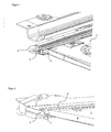
- FIG. 1 shows a section of a sunroof system. Under a leg of a regular U-shaped frame of the sunroof, not shown here, a displaceable trim part in the form of a sliding headliner 1 in a profile guide rail 2 made of aluminum is slidably disposed.
- the profile of the aluminum guide rail 2 is closed by an end stop 3.
- sliding sky 1 runs with a damping element 4 in the manner indicated in the end stop 3 into it. In this process, any noise is greatly reduced by the damping element 4 even at higher velocity stop.
- the jump Shifting sky 1 by the action of the damping element 4 not from the closed position out back into a partially open position.
- FIG. 2 Analogous to the representation of FIG. 1 shows FIG. 2 also a section of a sliding roof construction with sliding roof 1, which is located near a closed end position.
- an end stop 5 is formed on a frame end piece or frame front part.
- an end edge 6 is in an end position of the sliding headliner 1, an end edge 6 only with the continuously integrated therein damping element 4 with the end stop 5 in contact.
- FIG. 3 shows in a three-dimensional view, the damping element 4 according to the embodiments of FIG. 1 and FIG. 2 as a prefabricated component.
- this damping element 4 is a prefabricated injection molded part made of a rubber-elastic plastic material, which in the context of a manufacturing process according to the DE 102 03 196 A1 in an injection mold between an upper and a lower cover layer and at least partially enclosed by a foamed plastic layer.
- the damping element 4 after completion of the manufacturing process in the sliding sky 1 between the upper layer and the lower layer invisible running inner structure with recesses 7 and 8 bulges. Through these recesses foamed plastic material flows through in the manufacturing process.
- the bulges 8 also increase the surface of the damping element 4 with the enclosing foamed plastic material.
- a positive fixation in the sliding headliner 1 as an injection-molded product is effected in total in two ways.
- the damping element 4 is integrated into the sliding headliner 1 such that there is a continuous course of a visible outer surface.
- a buffer area 9, which is accessible for contact with an end stop 3, 5, is created on the damping element 4, which inserts itself into the shape of the end edge 6 of the sliding headliner 1 without requiring additional space.
- the damping element 4 has a bevel 10 in an installed position to the guide rail 2 oriented towards side. This ensures that the damping element 4 assumes no supporting or sliding properties in interaction with the guide rail 2 in the present embodiments. It is rather safely avoided by this shape, any contact between the damping element 4 and the guide rail 2 with appropriate tolerances.
- a continuous recess 11 is provided near the externally accessible buffer region 9, which reversibly provides the space required for increasing the elasticity of the damping element 4.
- the recess 11 serves as a receptacle of the prefabricated part for insertion into the mold during manufacture.
- a damping element 4 shown above which is embedded according to a manufacturing process of the applicant in the manufacturing process of a sliding headliner at a predetermined location compared to known sliding skies even shortening and thus saving additional space in the region of a sliding roof system. Even if such a damping element in a manner not shown here in a corresponding with Cavities and recesses prefabricated sliding headliner is injected, so is such a damping element seen over the life of the sliding headliner captive and also used in the production of a tool query comprehensible.
- the above-described damping elements are color coordinated with their immediate environment so that they are barely noticeable to adjacent components of a roof trim and thus almost invisible from the overall aesthetic impression ago.
Abstract
Description
Die vorliegende Erfindung betrifft ein verschiebbares Verkleidungsteil nach dem Oberbegriff von Anspruch 1.The present invention relates to a sliding trim part according to the preamble of
Gerade im Bereich der Personenkraftfahrzeuge sind als verschiebbare Verkleidungsteile Schiebehimmel für eine von einem Verschlusselement abdeckbare Dachöffnung einer Fahrgastkabine bekannt, die üblicherweise in Fahrzeuglängsrichtung in einer Ebene parallel zu einer Dachebene der Fahrzeugkabine verschiebbar sind. Aufgrund der großen wirtschaftlichen Bedeutung soll nachfolgend ohne Beschränkung der Erfindung nur auf diesen Anwendungsfall eingegangen werden.Especially in the field of passenger vehicles sliding as lining parts for a coverable by a closure element roof opening of a passenger cabin are known, which are usually displaceable in the vehicle longitudinal direction in a plane parallel to a roof plane of the vehicle cabin. Due to the great economic importance to be discussed below without limiting the invention only to this application.
Ein Schiebehimmel kann je nach Ausführungsform zur Regulierung der Entlüftung der Fahrgastzelle und bei Einsatz zusammen mit einem transparenten Deckel zur Abdeckung der Dachöffnung auch zur Regulierung bzw. Dämpfung eines Lichteinfalls genutzt werden. In einer Schließstellung eines derartigen Schiebehimmels ist neben der Sicht aus der Fahrgastkabine auf die Dachöffnung aus äsethischen Gründen auch ein Blick auf ein jeweiliges Verschlusselement verdeckt.Depending on the embodiment, a sliding headliner can be used to regulate the ventilation of the passenger compartment and, when used together with a transparent cover to cover the roof opening, also to regulate or dampen a light incidence. In a closed position of such a sliding headliner, as well as the view from the passenger cabin onto the roof opening, a view of a respective closure element is concealed for reasons of aesthetics.
Die
Da in modernen Kraftfahrzeugen gerade transparent abgedeckte Dachöffnungen von immer größeren Abmessungen Einsatz finden, werden Schiebehimmel fortschreitend mehr als Windschott ausgebildet und müssen daher fortschreitend zur Aufnahme von Kräften und einer Formgebung unter Wahrung einer optimalen Kopffreiheit und Geometrie einer Innenraumauskleidung innerhalb der Fahrgastzelle mechanisch verstärkt ausgeführt werden. Auch bei geringer eigener Bauhöhe und guter mechanischer Stabilität des Schiebehimmels als Dachraum-Verkleidungselement können nun aufgrund der Stabilität und der großen Fläche des Schiebehimmels Geräusche sogar verstärkt in den Fahrgastraum abgestrahlt werden. Im Gegensatz zu einer Betätigung des Verschlusselementes der Dachöffnung selber wird ein Schiebehimmel von Fahrer oder Beifahrer in der Regel auch von Hand bedient. Zur Dämpfung von Anschlaggeräuschen bei Erreichen einer jeweiligen Endstellung des Schiebehimmels oder auch zur Reduzierung der Verfahrgeschwindigkeit des Schiebehimmels bei dessen Betätigung werden daher nach dem Stand der Technik Gummipuffer an angrenzende unverschiebliche Bauteile des Schiebehimmels oder Dämpfungsleisten vorgesehen, wie beispielsweise in der
Es ist daher Aufgabe der vorliegenden Erfindung, ein verschiebbares Verkleidungsteil der eingangs genannten Art in Form eines Schiebehimmels mit guten akustischen Eigenschaften unter Senkung des Fertigungsaufwandes weiter zu bilden.It is therefore an object of the present invention to further develop a sliding trim part of the type mentioned in the form of a sliding headliner with good acoustic properties while reducing the manufacturing costs.
Diese Aufgabe wird jeweils durch die Merkmale des unabhängigen Anspruchs gelöst.This object is achieved in each case by the features of the independent claim.
Nach dem Stand der Technik werden an verschiebbaren Verkleidungsteilen in Form von Schiebehimmeln zur Montage von Gummipuffern spezielle Aufnahmen benötigt. Diese Aufnahmen sind in den beiden Bewegungsrichtungen gesehen im Bereich von zwei Stirnkanten des Schiebehimmels angeordnet.According to the prior art, special recordings are required on sliding trim parts in the form of sliding skylights for mounting rubber buffers. These shots are in The two directions of movement arranged in the region of two end edges of the sliding headliner.
Als ein Herstellverfahren für formstabile Schiebehimmel hat sich ein Verfahren gemäß der
Zur Abhilfe und als Lösung der vorstehend beschriebenen Aufgabe wird mindestens ein Dämpfungselement aus einem gummielastischen Kunststoffmaterial in den Schiebehimmel an einer vorbestimmten Dämpfungsposition dadurch integriert, dass das Dämpfungselement als vorgefertigtes Teil durch mindestens eine Komponente des Schiebehimmels umspritzt oder umschäumt ist, oder dadurch, dass das Dämpfungselement aus einem sich plastisch verfestigenden Material in eine entsprechende Ausnehmung des Schiebehimmels eingeformt oder insbesondere warm eingespritzt ist. Durch die vorstehend vorgeschlagenen Maßnahmen wird auch bei Integration eines Dämpfungselements ein Fortsatz als separates Bauteil eingespart und zugleich eine stetige und Bauraum-optimierte Außenkontur des Schiebehimmels geschaffen. Dadurch wird ein zur Verfügung stehender Bauraum nicht mehr eingeschränkt. Auch wird so zur Kostensenkung dadurch beigetragen, dass nicht mehr Bauraum und Material benötigt wird, als zwingend erforderlich ist. Zudem kann ein erfindungsgemäß angeordnetes Dämpfungselement, das vorzugsweise als Gummipuffer ausgeführt ist, auch über die Lebenszeit eines Schiebedachs hinweg selbst bei dauernder Belastung nicht mehr verloren gehen.To remedy this and as a solution to the above-described problem, at least one damping element made of a rubber-elastic plastic material is integrated in the sliding headliner at a predetermined damping position by encapsulating or foaming the damping element as a prefabricated part by at least one component of the sliding headliner or by the damping element is molded from a plastically solidifying material in a corresponding recess of the sliding headliner or injected in particular warm. The measures proposed above also result in the integration of a damping element saved an extension as a separate component while creating a steady and space-optimized outer contour of the sliding headliner. As a result, an available space is no longer limited. This also helps to reduce costs by not requiring more space and material than is absolutely necessary. In addition, an inventively arranged damping element, which is preferably designed as a rubber buffer, even over the lifetime of a sunroof away even with permanent load will not be lost.
Ein entsprechendes Fertigungsverfahren wird um den Schritt des Einlegens eines Fortsatzes im späteren Aufnehmen von mindestens einem Dämpfungselement zwischen die Bestandteile eines Schiebehimmels abgekürzt. Fortsätze als separate Elemente entfallen. Zudem stellen das Einlegen eines vorgefertigten Dämpfungselements, wie auch das nachträgliche Einspritzen eines Dämpfungselements in einen Schiebehimmel unter Anwendung eines plastifizierten Kunststoffmaterials Verfahrenschritte dar, die als Zwei-Komponenten- bzw. sogenannte 2K-Verfahren fertigungstechnisch gut beherrschbar sind. Zudem kann nun im Fertigungsprozess durch Abfrage der jeweiligen Maschinen sichergestellt werden, dass Dämpfungselemente auch wirklich in bzw. an einem gerade gefertigten Schiebehimmel angeordnet worden sind.A corresponding manufacturing method is abbreviated by the step of inserting an extension in the later recording of at least one damping element between the components of a sliding headliner. Extensions are omitted as separate elements. In addition, the insertion of a prefabricated damping element, as well as the subsequent injection of a damping element in a sliding sky using a plasticized plastic material process steps that are well manageable as two-component or so-called 2K process manufacturing technology. In addition, it can now be ensured in the production process by interrogating the respective machines that damping elements have actually been arranged in or on a currently manufactured sliding headliner.
Damit zeichnet sich jede der vorstehend aufgeführten Lösungen durch den Entfall spezieller Aufnahmen für Gummipuffer bei Reduzierung eines erforderlichen Bauraums aus. Zugleich ist eine Verliersicherheit eines Dämpfungselements während der Lebensdauer des Schiebedachs durch die Integration in den Dachhimmel sichergestellt. Zudem ist ein Dämpfungselement in einem erfindungsgemäßen Schiebehimmel im Einsatz vorzugsweise dadurch optisch kaum sichtbar, da es farblich an eine jeweils angrenzende Innenraumverkleidung angepasst ist.Thus, each of the solutions listed above is characterized by the elimination of special recordings for rubber buffers in reducing a required space. At the same time a loss of security of a damping element during the life of the sunroof is ensured by the integration in the headliner. In addition, a damping element in a sliding headliner according to the invention is preferably hardly visually visible in use because it is color-matched to a respective adjacent interior trim panel.
Nachfolgend werden Ausführungsbeispiele eines erfindungsgemäßen Schiebehimmels unter Darstellung eines Herstellungsverfahrens bei Bezugnahme auf die Figuren der Zeichnung zur Nennung weiterer Vorteile und Eigenheiten näher beschrieben. Es zeigen:
- Figur 1:
- einen Ausschnitt aus einer ersten Ausführungsform eines Schiebehimmels in dreidimensionaler Ansicht;
- Figur 2:
- eine Darstellung analog von
Figur 1 - Figur 3:
- eine dreidimensionale Ansicht eines vorgefertigten Dämpfungselements aus einem gummielastischen Kunststoffmaterial.
- FIG. 1:
- a detail of a first embodiment of a sliding sky in three-dimensional view;
- FIG. 2:
- a representation analogous to
FIG. 1 to a second embodiment of a sliding headliner and - FIG. 3:
- a three-dimensional view of a prefabricated damping element made of a rubber-elastic plastic material.
Über die zu beschreibenden Abbildungen der verschiedenen Ausführungsbeispiele hinweg werden nachfolgend einheitlich gleiche Elemente mit gleichen Namen und Bezugszeichen bezeichnet.In the following, uniformly identical elements with the same name and reference symbols will be referred to through the illustrations of the various embodiments to be described.
Die dreidimensionale Darstellung von
Analog zu der Darstellung von
Die Abbildung von
In der aus den Abbildungen der
Zur Erhöhung der Elastizität des Dämpfungselementes 4 ist nahe des von außen zugänglichen Pufferbereichs 9 eine durchgehende Ausnehmung 11 vorgesehen, die zur Erhöhung der Elastizität des Dämpfungselementes 4 erforderlichen Freiraum reversibel zur Verfügung stellt. Zugleich dient die Ausnehmung 11 als Aufnahme des vorgefertigten Teils zum Einlegen in die Form während der Fertigung.To increase the elasticity of the damping
Ohne separate Montage wird durch ein vorstehend dargestelltes Dämpfungselement 4, das gemäß eines Fertigungsverfahrens der Anmelderin im Fertigungsprozess eines Schiebehimmels an vorbestimmter Stelle eingebettet wird gegenüber bekannten Schiebehimmeln sogar noch einen Verkürzung und somit Einsparung zusätzlichen Bauraumes im Bereich eines Schiebedachsystems erzielt. Auch wenn ein derartiges Dämpfungselement in einer hier nicht weiter dargestellten Art und Weise in ein mit entsprechenden Hohlräumen und Aufnehmungen vorgefertigtes Schiebehimmelbauteil eingespritzt wird, so ist ein derartiges Dämpfungselement über die Lebensdauer des Schiebehimmels gesehen unverlierbar und zudem in der Fertigung über eine Werkzeugabfrage nachvollziehbar eingesetzt. Zudem sind vorstehend beschriebene Dämpfungselemente farblich mit ihrer unmittelbaren Umgebung so abzustimmen, dass sie gegenüber benachbarten Bestandteilen einer Dachraumverkleidung kaum auffallen und damit vom ästhetischen Gesamteindruck her nahezu unsichtbar sind.Without separate assembly is achieved by a damping
- 11
- Schiebehimmelsliding sky
- 22
- Alu-Profilleiste / FührungsschieneAluminum profile strip / guide rail
- 33
- Endanschlagend stop
- 44
- Dämpfungselementdamping element
- 55
- Endanschlagend stop
- 66
- Stirnkantefront edge
- 77
- Ausnehmungrecess
- 88th
- linsenförmige Wölbunglenticular vaulting
- 99
- Pufferbereichbuffer area
- 1010
- Schrägeslope
- 1111
- große Ausnehmunglarge recess
Claims (3)
- Slidable trim component in the form of a sliding roof lining (1) for a vehicle roof in which a roof opening is provided in a passenger cabin, said roof opening being coverable by a closure element, wherein the sliding roof lining (1) is arranged in a manner such that it can be slid in the longitudinal direction of the vehicle in a plane parallel to a roof plane of the vehicle cabin between two end positions in a guide rail (2), characterized in that at least one damping element (4), which is in contact with an end stop (3, 5) in an end position of the sliding roof lining (1) and is composed of rubber-elastic plastics material, is integrated in the sliding roof lining (1) at a predetermined damping position by the damping element (4) as a prefabricated part being insert moulded or foamed by at least one component of the sliding roof lining (1), or by the damping element (4) being moulded or injected from a plastically curing material into a corresponding recess of the sliding roof lining (1), the damping element (4) having a buffer region (9) which is accessible for contact with the end stop (3, 5) and is fitted into the shape of an end edge (6) of the sliding roof lining (1).
- Trim component according to Claim 1, characterized in that the sliding roof lining (1) has an upper cover layer, a lower cover layer which is visible from the passenger compartment, and a foamed plastics layer which binds said two cover layers rigidly to each other at a predefinable distance and in which the damping element (4) for striking against the end stop (3, 5) of the guide rail (2) is provided.
- Trim component according to one of the preceding claims, characterized in that the damping element (4) is matched in colour to a respectively adjacent interior trim.
Applications Claiming Priority (1)
| Application Number | Priority Date | Filing Date | Title |
|---|---|---|---|
| DE102006002007A DE102006002007A1 (en) | 2006-01-16 | 2006-01-16 | Sliding covering part and method for its production |
Publications (2)
| Publication Number | Publication Date |
|---|---|
| EP1808320A1 EP1808320A1 (en) | 2007-07-18 |
| EP1808320B1 true EP1808320B1 (en) | 2009-11-18 |
Family
ID=37863682
Family Applications (1)
| Application Number | Title | Priority Date | Filing Date |
|---|---|---|---|
| EP07000730A Not-in-force EP1808320B1 (en) | 2006-01-16 | 2007-01-15 | Slidable trim component and method of manufacturing the same |
Country Status (3)
| Country | Link |
|---|---|
| EP (1) | EP1808320B1 (en) |
| AT (1) | ATE448966T1 (en) |
| DE (2) | DE102006002007A1 (en) |
Families Citing this family (2)
| Publication number | Priority date | Publication date | Assignee | Title |
|---|---|---|---|---|
| DE102009005211B4 (en) * | 2009-01-20 | 2015-04-02 | Webasto Ag | Sliding roof with support for functional element |
| DE102011102895A1 (en) * | 2011-05-31 | 2012-12-06 | GM Global Technology Operations LLC (n. d. Gesetzen des Staates Delaware) | Retaining device, shading system, motor vehicle and method for this |
Family Cites Families (5)
| Publication number | Priority date | Publication date | Assignee | Title |
|---|---|---|---|---|
| DE19624734C2 (en) * | 1996-06-21 | 2000-11-16 | Fehrer F S Gmbh & Co Kg | Sliding panel with fasteners and method of manufacture |
| JP2001138744A (en) * | 1999-11-18 | 2001-05-22 | Aisin Seiki Co Ltd | Sunshade for vehicle sunroof |
| DE10125764A1 (en) * | 2001-05-22 | 2002-12-05 | Fehrer F S Gmbh & Co Kg | Connector element for immovably or movably installing an areal plastic component comprises plastic material which is injected around the fixing section and/or the installation section |
| DE10203196A1 (en) | 2002-01-25 | 2003-08-07 | Webasto Vehicle Sys Int Gmbh | Vehicle sun roof comprises a sandwich construction with outer layers and an injected foam layer between them |
| DE102004007887B4 (en) | 2004-02-17 | 2007-02-01 | Johnson Controls Headliner Gmbh | Damping strip and frame, in particular for a sunroof roof, method for producing a damping strip or a frame, in particular for a sunroof headliner |
-
2006
- 2006-01-16 DE DE102006002007A patent/DE102006002007A1/en not_active Withdrawn
-
2007
- 2007-01-15 DE DE502007001994T patent/DE502007001994D1/en active Active
- 2007-01-15 AT AT07000730T patent/ATE448966T1/en active
- 2007-01-15 EP EP07000730A patent/EP1808320B1/en not_active Not-in-force
Also Published As
| Publication number | Publication date |
|---|---|
| DE102006002007A1 (en) | 2007-07-19 |
| EP1808320A1 (en) | 2007-07-18 |
| DE502007001994D1 (en) | 2009-12-31 |
| ATE448966T1 (en) | 2009-12-15 |
Similar Documents
| Publication | Publication Date | Title |
|---|---|---|
| EP2463133B1 (en) | Seal for a glass arrangement | |
| EP2463134B1 (en) | Seal system for a window arrangement including manufacturing method | |
| EP1750960B2 (en) | Vehicle roof | |
| DE102008021717B4 (en) | Roof rail with shaped end | |
| DE60036311T3 (en) | USE OF GLAZING WITH A PROFILEED BAND FOR ITS INSTALLATION IN ONE OPENING | |
| EP2684744A1 (en) | Trim part for motor vehicles and method for its production | |
| DE102014010420B4 (en) | Vehicle roof with a roof module | |
| DE19842456A1 (en) | Resin molded articles | |
| WO2016198217A1 (en) | Profiled strip, system and method for producing a profiled strip | |
| DE102006015091B4 (en) | Motor vehicle interior panel having a unified seal, method for its manufacture and thus equipped vehicle | |
| DE102012003258A1 (en) | Return air lock for venting the interior of a motor vehicle | |
| EP2006165A1 (en) | Interior lining with integrated airbag cover for a motor vehicle and method for its manufacture | |
| WO1996025282A1 (en) | Process for producing a plastic cladding component and cladding component produced especially by said process | |
| DE102010036475A1 (en) | Bumper attachment, bumper assembly and motor vehicle | |
| DE2818300A1 (en) | KIT FOR AT LEAST PARTIAL MODIFICATION OF THE SHAPE OF THE ROOF OF A CAR | |
| DE3020997A1 (en) | Impact absorbing car bumper - has soft plastics moulding between metal support and outer plastics cover | |
| EP1808320B1 (en) | Slidable trim component and method of manufacturing the same | |
| EP3085563A1 (en) | Injection molded water drain strip and arrangement for a vehicle trim | |
| EP1747922B1 (en) | Sliding window assembly for automotive vehicle | |
| DE102012022899A1 (en) | Connector for supporting bumper of motor car to assembly carrier, has rear clutch element arranged in rear portion of top surface, and extended forward along longitudinal direction of car to overlap top surface to supporting element | |
| EP1348585B1 (en) | Displaceable panel for vehicle roof and sliding roof module | |
| DE102014016489A1 (en) | Door edge protection for arrangement on a motor vehicle door | |
| DE202007009971U1 (en) | Sliding sunshade for a motor vehicle | |
| DE102004044159A1 (en) | Composite component, in particular body attachment for a vehicle, and method for producing such a composite component | |
| DE102017211291B4 (en) | Window molding arrangement and method for producing a window molding arrangement |
Legal Events
| Date | Code | Title | Description |
|---|---|---|---|
| PUAI | Public reference made under article 153(3) epc to a published international application that has entered the european phase |
Free format text: ORIGINAL CODE: 0009012 |
|
| 17P | Request for examination filed |
Effective date: 20070201 |
|
| AK | Designated contracting states |
Kind code of ref document: A1 Designated state(s): AT BE BG CH CY CZ DE DK EE ES FI FR GB GR HU IE IS IT LI LT LU LV MC NL PL PT RO SE SI SK TR |
|
| AX | Request for extension of the european patent |
Extension state: AL BA HR MK YU |
|
| 17Q | First examination report despatched |
Effective date: 20080213 |
|
| AKX | Designation fees paid |
Designated state(s): AT BE BG CH CY CZ DE DK EE ES FI FR GB GR HU IE IS IT LI LT LU LV MC NL PL PT RO SE SI SK TR |
|
| GRAP | Despatch of communication of intention to grant a patent |
Free format text: ORIGINAL CODE: EPIDOSNIGR1 |
|
| GRAS | Grant fee paid |
Free format text: ORIGINAL CODE: EPIDOSNIGR3 |
|
| GRAA | (expected) grant |
Free format text: ORIGINAL CODE: 0009210 |
|
| AK | Designated contracting states |
Kind code of ref document: B1 Designated state(s): AT BE BG CH CY CZ DE DK EE ES FI FR GB GR HU IE IS IT LI LT LU LV MC NL PL PT RO SE SI SK TR |
|
| REG | Reference to a national code |
Ref country code: GB Ref legal event code: FG4D Free format text: NOT ENGLISH |
|
| REG | Reference to a national code |
Ref country code: CH Ref legal event code: EP |
|
| REG | Reference to a national code |
Ref country code: IE Ref legal event code: FG4D |
|
| REF | Corresponds to: |
Ref document number: 502007001994 Country of ref document: DE Date of ref document: 20091231 Kind code of ref document: P |
|
| REG | Reference to a national code |
Ref country code: NL Ref legal event code: VDEP Effective date: 20091118 |
|
| LTIE | Lt: invalidation of european patent or patent extension |
Effective date: 20091118 |
|
| PG25 | Lapsed in a contracting state [announced via postgrant information from national office to epo] |
Ref country code: SE Free format text: LAPSE BECAUSE OF FAILURE TO SUBMIT A TRANSLATION OF THE DESCRIPTION OR TO PAY THE FEE WITHIN THE PRESCRIBED TIME-LIMIT Effective date: 20091118 Ref country code: PT Free format text: LAPSE BECAUSE OF FAILURE TO SUBMIT A TRANSLATION OF THE DESCRIPTION OR TO PAY THE FEE WITHIN THE PRESCRIBED TIME-LIMIT Effective date: 20100318 Ref country code: LT Free format text: LAPSE BECAUSE OF FAILURE TO SUBMIT A TRANSLATION OF THE DESCRIPTION OR TO PAY THE FEE WITHIN THE PRESCRIBED TIME-LIMIT Effective date: 20091118 Ref country code: IS Free format text: LAPSE BECAUSE OF FAILURE TO SUBMIT A TRANSLATION OF THE DESCRIPTION OR TO PAY THE FEE WITHIN THE PRESCRIBED TIME-LIMIT Effective date: 20100318 Ref country code: FI Free format text: LAPSE BECAUSE OF FAILURE TO SUBMIT A TRANSLATION OF THE DESCRIPTION OR TO PAY THE FEE WITHIN THE PRESCRIBED TIME-LIMIT Effective date: 20091118 Ref country code: ES Free format text: LAPSE BECAUSE OF FAILURE TO SUBMIT A TRANSLATION OF THE DESCRIPTION OR TO PAY THE FEE WITHIN THE PRESCRIBED TIME-LIMIT Effective date: 20100228 |
|
| PG25 | Lapsed in a contracting state [announced via postgrant information from national office to epo] |
Ref country code: SI Free format text: LAPSE BECAUSE OF FAILURE TO SUBMIT A TRANSLATION OF THE DESCRIPTION OR TO PAY THE FEE WITHIN THE PRESCRIBED TIME-LIMIT Effective date: 20091118 Ref country code: PL Free format text: LAPSE BECAUSE OF FAILURE TO SUBMIT A TRANSLATION OF THE DESCRIPTION OR TO PAY THE FEE WITHIN THE PRESCRIBED TIME-LIMIT Effective date: 20091118 Ref country code: LV Free format text: LAPSE BECAUSE OF FAILURE TO SUBMIT A TRANSLATION OF THE DESCRIPTION OR TO PAY THE FEE WITHIN THE PRESCRIBED TIME-LIMIT Effective date: 20091118 Ref country code: CY Free format text: LAPSE BECAUSE OF FAILURE TO SUBMIT A TRANSLATION OF THE DESCRIPTION OR TO PAY THE FEE WITHIN THE PRESCRIBED TIME-LIMIT Effective date: 20091118 |
|
| REG | Reference to a national code |
Ref country code: IE Ref legal event code: FD4D |
|
| PG25 | Lapsed in a contracting state [announced via postgrant information from national office to epo] |
Ref country code: RO Free format text: LAPSE BECAUSE OF FAILURE TO SUBMIT A TRANSLATION OF THE DESCRIPTION OR TO PAY THE FEE WITHIN THE PRESCRIBED TIME-LIMIT Effective date: 20091118 Ref country code: NL Free format text: LAPSE BECAUSE OF FAILURE TO SUBMIT A TRANSLATION OF THE DESCRIPTION OR TO PAY THE FEE WITHIN THE PRESCRIBED TIME-LIMIT Effective date: 20091118 Ref country code: IE Free format text: LAPSE BECAUSE OF FAILURE TO SUBMIT A TRANSLATION OF THE DESCRIPTION OR TO PAY THE FEE WITHIN THE PRESCRIBED TIME-LIMIT Effective date: 20091118 Ref country code: EE Free format text: LAPSE BECAUSE OF FAILURE TO SUBMIT A TRANSLATION OF THE DESCRIPTION OR TO PAY THE FEE WITHIN THE PRESCRIBED TIME-LIMIT Effective date: 20091118 Ref country code: DK Free format text: LAPSE BECAUSE OF FAILURE TO SUBMIT A TRANSLATION OF THE DESCRIPTION OR TO PAY THE FEE WITHIN THE PRESCRIBED TIME-LIMIT Effective date: 20091118 Ref country code: BG Free format text: LAPSE BECAUSE OF FAILURE TO SUBMIT A TRANSLATION OF THE DESCRIPTION OR TO PAY THE FEE WITHIN THE PRESCRIBED TIME-LIMIT Effective date: 20100218 |
|
| BERE | Be: lapsed |
Owner name: WEBASTO A.G. Effective date: 20100131 |
|
| PG25 | Lapsed in a contracting state [announced via postgrant information from national office to epo] |
Ref country code: SK Free format text: LAPSE BECAUSE OF FAILURE TO SUBMIT A TRANSLATION OF THE DESCRIPTION OR TO PAY THE FEE WITHIN THE PRESCRIBED TIME-LIMIT Effective date: 20091118 Ref country code: MC Free format text: LAPSE BECAUSE OF NON-PAYMENT OF DUE FEES Effective date: 20100131 Ref country code: CZ Free format text: LAPSE BECAUSE OF FAILURE TO SUBMIT A TRANSLATION OF THE DESCRIPTION OR TO PAY THE FEE WITHIN THE PRESCRIBED TIME-LIMIT Effective date: 20091118 |
|
| PLBE | No opposition filed within time limit |
Free format text: ORIGINAL CODE: 0009261 |
|
| STAA | Information on the status of an ep patent application or granted ep patent |
Free format text: STATUS: NO OPPOSITION FILED WITHIN TIME LIMIT |
|
| REG | Reference to a national code |
Ref country code: FR Ref legal event code: ST Effective date: 20100930 |
|
| 26N | No opposition filed |
Effective date: 20100819 |
|
| PG25 | Lapsed in a contracting state [announced via postgrant information from national office to epo] |
Ref country code: GR Free format text: LAPSE BECAUSE OF FAILURE TO SUBMIT A TRANSLATION OF THE DESCRIPTION OR TO PAY THE FEE WITHIN THE PRESCRIBED TIME-LIMIT Effective date: 20100219 Ref country code: FR Free format text: LAPSE BECAUSE OF NON-PAYMENT OF DUE FEES Effective date: 20100201 |
|
| PG25 | Lapsed in a contracting state [announced via postgrant information from national office to epo] |
Ref country code: BE Free format text: LAPSE BECAUSE OF NON-PAYMENT OF DUE FEES Effective date: 20100131 |
|
| PG25 | Lapsed in a contracting state [announced via postgrant information from national office to epo] |
Ref country code: IT Free format text: LAPSE BECAUSE OF FAILURE TO SUBMIT A TRANSLATION OF THE DESCRIPTION OR TO PAY THE FEE WITHIN THE PRESCRIBED TIME-LIMIT Effective date: 20091118 |
|
| REG | Reference to a national code |
Ref country code: CH Ref legal event code: PL |
|
| GBPC | Gb: european patent ceased through non-payment of renewal fee |
Effective date: 20110115 |
|
| PG25 | Lapsed in a contracting state [announced via postgrant information from national office to epo] |
Ref country code: LI Free format text: LAPSE BECAUSE OF NON-PAYMENT OF DUE FEES Effective date: 20110131 Ref country code: CH Free format text: LAPSE BECAUSE OF NON-PAYMENT OF DUE FEES Effective date: 20110131 |
|
| PG25 | Lapsed in a contracting state [announced via postgrant information from national office to epo] |
Ref country code: GB Free format text: LAPSE BECAUSE OF NON-PAYMENT OF DUE FEES Effective date: 20110115 |
|
| PG25 | Lapsed in a contracting state [announced via postgrant information from national office to epo] |
Ref country code: HU Free format text: LAPSE BECAUSE OF FAILURE TO SUBMIT A TRANSLATION OF THE DESCRIPTION OR TO PAY THE FEE WITHIN THE PRESCRIBED TIME-LIMIT Effective date: 20100519 Ref country code: LU Free format text: LAPSE BECAUSE OF NON-PAYMENT OF DUE FEES Effective date: 20100115 |
|
| PG25 | Lapsed in a contracting state [announced via postgrant information from national office to epo] |
Ref country code: TR Free format text: LAPSE BECAUSE OF FAILURE TO SUBMIT A TRANSLATION OF THE DESCRIPTION OR TO PAY THE FEE WITHIN THE PRESCRIBED TIME-LIMIT Effective date: 20091118 |
|
| REG | Reference to a national code |
Ref country code: AT Ref legal event code: MM01 Ref document number: 448966 Country of ref document: AT Kind code of ref document: T Effective date: 20120115 |
|
| PG25 | Lapsed in a contracting state [announced via postgrant information from national office to epo] |
Ref country code: AT Free format text: LAPSE BECAUSE OF NON-PAYMENT OF DUE FEES Effective date: 20120115 |
|
| PGFP | Annual fee paid to national office [announced via postgrant information from national office to epo] |
Ref country code: DE Payment date: 20200123 Year of fee payment: 14 |
|
| REG | Reference to a national code |
Ref country code: DE Ref legal event code: R119 Ref document number: 502007001994 Country of ref document: DE |
|
| PG25 | Lapsed in a contracting state [announced via postgrant information from national office to epo] |
Ref country code: DE Free format text: LAPSE BECAUSE OF NON-PAYMENT OF DUE FEES Effective date: 20210803 |