EP1747453B1 - Chargement sous controle d'un specimen - Google Patents
Chargement sous controle d'un specimen Download PDFInfo
- Publication number
- EP1747453B1 EP1747453B1 EP04804684A EP04804684A EP1747453B1 EP 1747453 B1 EP1747453 B1 EP 1747453B1 EP 04804684 A EP04804684 A EP 04804684A EP 04804684 A EP04804684 A EP 04804684A EP 1747453 B1 EP1747453 B1 EP 1747453B1
- Authority
- EP
- European Patent Office
- Prior art keywords
- sample
- specimen
- injection channel
- injection
- sep
- Prior art date
- Legal status (The legal status is an assumption and is not a legal conclusion. Google has not performed a legal analysis and makes no representation as to the accuracy of the status listed.)
- Active
Links
- 238000011068 loading method Methods 0.000 title claims abstract description 45
- 238000002347 injection Methods 0.000 claims abstract description 136
- 239000007924 injection Substances 0.000 claims abstract description 136
- 238000000926 separation method Methods 0.000 claims abstract description 53
- 239000012530 fluid Substances 0.000 claims abstract description 25
- 230000005684 electric field Effects 0.000 claims description 26
- 238000000034 method Methods 0.000 claims description 9
- 239000011159 matrix material Substances 0.000 description 17
- 238000004458 analytical method Methods 0.000 description 14
- 238000007873 sieving Methods 0.000 description 14
- 238000009826 distribution Methods 0.000 description 11
- FAPWRFPIFSIZLT-UHFFFAOYSA-M Sodium chloride Chemical compound [Na+].[Cl-] FAPWRFPIFSIZLT-UHFFFAOYSA-M 0.000 description 10
- 150000002500 ions Chemical class 0.000 description 10
- 235000018102 proteins Nutrition 0.000 description 6
- 108090000623 proteins and genes Proteins 0.000 description 6
- 102000004169 proteins and genes Human genes 0.000 description 6
- 150000001450 anions Chemical class 0.000 description 5
- 238000001962 electrophoresis Methods 0.000 description 5
- 238000005259 measurement Methods 0.000 description 5
- 239000011780 sodium chloride Substances 0.000 description 5
- 101001121580 Enterobacteria phage PRD1 Adsorption protein P2 Proteins 0.000 description 4
- 101710107904 NADH-ubiquinone oxidoreductase subunit 9 Proteins 0.000 description 4
- 101001125164 Parietaria judaica Probable non-specific lipid-transfer protein 2 Proteins 0.000 description 4
- 101710132845 Protein P1 Proteins 0.000 description 4
- 101000580771 Pseudomonas phage phi6 RNA-directed RNA polymerase Proteins 0.000 description 4
- 101001121571 Rice tungro bacilliform virus (isolate Philippines) Protein P2 Proteins 0.000 description 4
- 230000007423 decrease Effects 0.000 description 4
- 239000000203 mixture Substances 0.000 description 4
- 230000036962 time dependent Effects 0.000 description 4
- HRPVXLWXLXDGHG-UHFFFAOYSA-N Acrylamide Chemical compound NC(=O)C=C HRPVXLWXLXDGHG-UHFFFAOYSA-N 0.000 description 2
- VEXZGXHMUGYJMC-UHFFFAOYSA-M Chloride anion Chemical compound [Cl-] VEXZGXHMUGYJMC-UHFFFAOYSA-M 0.000 description 2
- DBMJMQXJHONAFJ-UHFFFAOYSA-M Sodium laurylsulphate Chemical compound [Na+].CCCCCCCCCCCCOS([O-])(=O)=O DBMJMQXJHONAFJ-UHFFFAOYSA-M 0.000 description 2
- 150000001413 amino acids Chemical class 0.000 description 2
- 150000001768 cations Chemical class 0.000 description 2
- 238000010586 diagram Methods 0.000 description 2
- 238000000746 purification Methods 0.000 description 2
- 229940083575 sodium dodecyl sulfate Drugs 0.000 description 2
- 235000019333 sodium laurylsulphate Nutrition 0.000 description 2
- 239000000126 substance Substances 0.000 description 2
- DGAQECJNVWCQMB-PUAWFVPOSA-M Ilexoside XXIX Chemical compound C[C@@H]1CC[C@@]2(CC[C@@]3(C(=CC[C@H]4[C@]3(CC[C@@H]5[C@@]4(CC[C@@H](C5(C)C)OS(=O)(=O)[O-])C)C)[C@@H]2[C@]1(C)O)C)C(=O)O[C@H]6[C@@H]([C@H]([C@@H]([C@H](O6)CO)O)O)O.[Na+] DGAQECJNVWCQMB-PUAWFVPOSA-M 0.000 description 1
- 229920003171 Poly (ethylene oxide) Polymers 0.000 description 1
- 239000000872 buffer Substances 0.000 description 1
- 239000000969 carrier Substances 0.000 description 1
- -1 chloride anions Chemical class 0.000 description 1
- 239000004020 conductor Substances 0.000 description 1
- 230000003247 decreasing effect Effects 0.000 description 1
- 230000001419 dependent effect Effects 0.000 description 1
- 238000001514 detection method Methods 0.000 description 1
- 230000000694 effects Effects 0.000 description 1
- 238000005516 engineering process Methods 0.000 description 1
- 238000002474 experimental method Methods 0.000 description 1
- 238000000605 extraction Methods 0.000 description 1
- 238000001502 gel electrophoresis Methods 0.000 description 1
- 239000011521 glass Substances 0.000 description 1
- 229920003088 hydroxypropyl methyl cellulose Polymers 0.000 description 1
- 235000010979 hydroxypropyl methyl cellulose Nutrition 0.000 description 1
- 239000001866 hydroxypropyl methyl cellulose Substances 0.000 description 1
- UFVKGYZPFZQRLF-UHFFFAOYSA-N hydroxypropyl methyl cellulose Chemical compound OC1C(O)C(OC)OC(CO)C1OC1C(O)C(O)C(OC2C(C(O)C(OC3C(C(O)C(O)C(CO)O3)O)C(CO)O2)O)C(CO)O1 UFVKGYZPFZQRLF-UHFFFAOYSA-N 0.000 description 1
- 229940088644 n,n-dimethylacrylamide Drugs 0.000 description 1
- YLGYACDQVQQZSW-UHFFFAOYSA-N n,n-dimethylprop-2-enamide Chemical compound CN(C)C(=O)C=C YLGYACDQVQQZSW-UHFFFAOYSA-N 0.000 description 1
- 230000007935 neutral effect Effects 0.000 description 1
- 230000000704 physical effect Effects 0.000 description 1
- 229920003023 plastic Polymers 0.000 description 1
- 239000004033 plastic Substances 0.000 description 1
- 229920002401 polyacrylamide Polymers 0.000 description 1
- 229920000642 polymer Polymers 0.000 description 1
- 229920000036 polyvinylpyrrolidone Polymers 0.000 description 1
- 239000001267 polyvinylpyrrolidone Substances 0.000 description 1
- 235000013855 polyvinylpyrrolidone Nutrition 0.000 description 1
- 235000004252 protein component Nutrition 0.000 description 1
- 150000003839 salts Chemical class 0.000 description 1
- 238000005070 sampling Methods 0.000 description 1
- 230000035945 sensitivity Effects 0.000 description 1
- 229910052708 sodium Inorganic materials 0.000 description 1
- 239000011734 sodium Substances 0.000 description 1
- 238000009827 uniform distribution Methods 0.000 description 1
Images


Classifications
-
- G—PHYSICS
- G01—MEASURING; TESTING
- G01N—INVESTIGATING OR ANALYSING MATERIALS BY DETERMINING THEIR CHEMICAL OR PHYSICAL PROPERTIES
- G01N27/00—Investigating or analysing materials by the use of electric, electrochemical, or magnetic means
- G01N27/26—Investigating or analysing materials by the use of electric, electrochemical, or magnetic means by investigating electrochemical variables; by using electrolysis or electrophoresis
- G01N27/416—Systems
- G01N27/447—Systems using electrophoresis
- G01N27/44704—Details; Accessories
- G01N27/44743—Introducing samples
-
- G—PHYSICS
- G01—MEASURING; TESTING
- G01N—INVESTIGATING OR ANALYSING MATERIALS BY DETERMINING THEIR CHEMICAL OR PHYSICAL PROPERTIES
- G01N27/00—Investigating or analysing materials by the use of electric, electrochemical, or magnetic means
- G01N27/26—Investigating or analysing materials by the use of electric, electrochemical, or magnetic means by investigating electrochemical variables; by using electrolysis or electrophoresis
- G01N27/416—Systems
- G01N27/447—Systems using electrophoresis
- G01N27/44756—Apparatus specially adapted therefor
- G01N27/44791—Microapparatus
-
- G—PHYSICS
- G01—MEASURING; TESTING
- G01N—INVESTIGATING OR ANALYSING MATERIALS BY DETERMINING THEIR CHEMICAL OR PHYSICAL PROPERTIES
- G01N30/00—Investigating or analysing materials by separation into components using adsorption, absorption or similar phenomena or using ion-exchange, e.g. chromatography or field flow fractionation
- G01N30/02—Column chromatography
- G01N30/26—Conditioning of the fluid carrier; Flow patterns
- G01N30/38—Flow patterns
- G01N30/46—Flow patterns using more than one column
- G01N30/461—Flow patterns using more than one column with serial coupling of separation columns
Definitions
- the present invention relates to injecting a sample of a specimen.
- Modem biochemical analyzers can achieve a very high degree of sensitivity and comprise a very low detection limit. Consequently the amount of specimen used for chemical and/or biological analysis has been decreasing over the last few years and is now in the order of some microliter.
- State of the art microfluidic analyzer systems as, for example, the 2100 Bioanalyzer or the 5100 ALP Bioanalyzer by Agilent Technologies use even smaller amounts of specimen for analysis. In these analyzers a sample of the specimen is loaded and cut out for further analysis processing.
- external and sometimes not influenceable parameters like concentration gradients within the specimen's volume, type of specimen or purification conditions might cause a strong impact on the sample and on the analysis.
- Microfluidic devices with sample injection are also known from WO 01/59440 A2 , WO 2005/068993 A1 , EP 0653631 A2 , and DE 19927535 A1 , the teaching of the latter forming the preamble to claim 1.
- the improved loading reduces the affect of concentration gradients within the specimen and purification conditions.
- the specimen to be analyzed normally comprises a plurality of different components, components having different concentration within the specimen. Each of those components might have different mass, size or even comprise an electrical charge.
- a typical example of such specimen include a mixture of proteins, amino acids or DNA and RNA, respectively. Particularly such protein specimen can also vary dramatically in salt content. Additionally some of those components inherit an electrical charge, while other are electrically neutral.
- the specimen might comprise a protein which is very small in size and mass but with a high electrical charge. Another protein might comprise a higher mass and only few electrical charges. Specimen components can also be surrounded by electrically charged carriers for analysis.
- microfluidic systems the specimen is loaded into a so-called injection channel. At a specific area of the injection channel a sample is cut out (injected) from the specimen and the channel and processed for further analysis.
- the objective for optimal injection is that the sample composition of the injected sample exactly matches the actual composition and distribution of the specimen.
- a sample loading device comprises an injection channel having a sample injection spot.
- the injection channel is designed for a specimen comprising fluid to be injected.
- the sample loading device comprises transporting the specimen within the fluid along the injection channel.
- the specimen with its different components, having a different size, mass or electrical charge is transported along the injection channel and also transported along the sample injection spot.
- the sample loading device further comprises a separation device for separating a sample from the specimen starting at the sample injection spot.
- this injected sample should match the actual specimen's content. If the distribution along the injection channel is mainly uniform, then the content at the sample injection point will be similar to the content of the whole specimen. However, the distribution depends on the volume used for the specimen and the way the sample is loaded into the injection channel. Therefore a control unit is provided and coupled to the loading device.
- the control unit is adapted for controlling the loading device by analyzing a physical parameter of the fluid. It also controls the separation device. Depending on the physical parameter of the fluid the control unit regulates the loading device for loading a sample from the specimen. In other words, the time for loading the sample from the specimen is now dependent on the physical parameter of the fluid containing the specimen. This will allow the loading procedure to dynamically adapt the loading process to the electrical or physical properties of the fluid containing the specimen.
- the loading process is monitored by the control unit using the measurement of the physical parameter of the fluid.
- the physical parameter is a time-dependent electrical parameter of the fluid. Such a parameter can be used if the specimen within the fluid comprises electrically charged components.
- the parameter is a time-dependent resistance of the fluid along the injection channel. Measuring the resistance along the injection channel allows information about the distribution of the specimen having electrical charged components along the injection channel.
- the parameter detected comprises a time-dependent current flow along the injection channel or a time dependent voltage drop.
- the injection channel comprises a specimen reservoir arranged between a first part and a second part of the injection channel.
- the reservoir comprises a volume for the specimen.
- the volume might be bigger than the volume of the injection channel. A uniform distribution along the injection channel is achieved.
- distributing the specimen along the injection channel is adapted for generating an electrical field along the injection channel.
- the first electrode is arranged near a first end of the injection channel and the second electrode arranged near a second end of the injection channel.
- the sample injection spot is arranged between the first and second electrode. Applying an electrical field to the first and second electrode will pull electrically charged components of the specimen along the injection channel.
- the control unit for detecting an electrical parameter of the fluid is coupled to the first and second electrodes.
- the control unit might be adapted for measuring the current flowing through the injection channel, the voltage drop or the resistance, respectively, along the injection channel.
- the separation device comprising a separation channel is connected to the sampling injection spot.
- Injection channel and separation channel are connected together in the sample injection spot. In one embodiment they form a cross-like connection.
- the separation device might comprise a first electrode and a second electrode arranged in the separation channel, used for separating a sample out of the injection channel into the separation channel. Applying an electrical field of the first and second electrode of the separation channel will pull a sample from the injection spot into the separation channel thereby separating the sample from the rest of the specimen. The time for applying such an electrical field is controlled by the control unit for detecting the physical or electrical parameter of fluid.
- the injection channel comprises a sieving matrix fed into the injection channel before the specimen's loading and injection, the feeding matrix comprising PDMA, acrylamide, or another polymeric substance.
- the feeding matrix comprising PDMA, acrylamide, or another polymeric substance.
- Such sieving matrix allows separating and distributing different components of different size and mass along the injection channel and the separation channel.
- the fluid comprising the sieving matrix might be used especially for electrophoresis analysis.
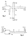
- Figure 1 shows a top view of an embodiment of the present invention.
- Figure 2 shows a different view of the same embodiment.
- Figure 3 is a concentration time diagram along the injection channel of an embodiment for different components of an injected specimen.
- FIG. 4 shows another embodiment.
- Figure 5 shows the separation of a specimen into its components after applying an electrical field.
- Figure 6 shows a current time diagram determining the correct separation time for different specimens.
- Figure 7 shows the current or voltage behavior over time for a loaded specimen.
- Figure 1 shows an embodiment of a microfluidic sample loading device used for electrophoresis analysis.
- electrophoresis analysis an electrical field is applied to a specimen comprising electrically charged components.
- components might be, for example, electrically charged amino acids or proteins or RNA or DNA or other biomolecules.
- a force moves the charged components towards the electrodes providing the electric field. Due to different electrical charges of each component and different masses the moving velocity of the components will be different.
- smaller components or components with a high electrical charge to mass ratio move faster towards the electrodes of the electrical field than larger components or components with a low charge to mass ratio. Therefore the specimen will separate into the different components.
- Figure 5 shows an example of a standard gel electrophoresis experiment of specimen having electrically charged components of different sizes and masses.
- a sample of the specimen is injected into a so-called separation channel S shown herein at the areas SEP.
- the electrical field applied to the separation channel forces the negative charged components to migrate towards the positive electrode.
- the sample loading device comprises an injection channel I having a sample extraction point INJ.
- a separation channel S is crossing the injection channel I. Both channels comprise only very small volumes in the range of micro- or even nanoliters. They may be formed in a glass or plastic body as capillary vessels.
- the separation channel S comprises a first separation electrode Sep-in the upper part of the separation channel S and a second electrode Sep+ at the lower part of the separation channel.
- the electrodes are formed of a conductive material and adapted to apply a voltage or current to them. The voltage or current will generate an electrical field in the separation channel S.
- the lower part of the separation channel S is much longer than the upper part and used to separate the different components (anions) of the sample to be analyzed.
- the injection channel I comprises a first electrode Uinj- on one end and a second electrode Uinj+ on the other end.
- the electrodes are conductive. By applying a voltage or current to both electrodes an electrical field is generated along the injection channel I.
- the electrical field may be uniform and constant along the channel. This would result a constant force on the specimen. However non-homogenous electrical fields are also possible.
- the volume of the reservoir Res is large compared to the volumes of the injection channel and the separation channel.
- the reservoir Res comprises a volume in the magnitude of a few microliter while the volumes of the injection channel I and the separation channel S comprise only a few nanoliters.
- the volume of the injection channel comprises 12 nanoliters, while the volume of the reservoir Res is about 500 nanoliters.
- the reservoir Res comprises an inlet for feeding a specimen into the reservoir Res and an outlet VAC where vacuum for hydrodynamic specimen movement is applied.
- the distance between the reservoir Res and the sample injection spot in this example is only a few hundred micrometers, for example 200 micrometers.
- the injection channel as well as the separation channel is filled with a sieving matrix.
- the sieving matrix offers additional resistance for the components of the specimen, when moving towards the electrodes after applying an electrical field.
- the sieving matrix might comprise PDMA (poly-N,N-dimethyl-acrylamide), polyacrylamide, polyethylene oxide, polyvinylpyrrolidone, hydroxypropylmethylcellulose or other polymeric matrices.
- the specimen is then drawn into the reservoir hydrodynamically by applying a vacuum on the outlet VAC, moving the specimen into the reservoir. Once the reservoir and the inlet and outlet areas are filled by the specimen the vacuum is turned off and an electrical field is applied across the first electrode Uinj- and the second electrode Uinj+ of the injection channel I.
- the different components within the specimen will now electrokinetically move along the injection channel towards the first electrode or the second electrode.
- the negative charged components of the specimen will be moving towards the second electrode Uinj+.
- the portion of the specimen at the sample injection spot INJ is injected into the separation channel S. This is done by modifying the electrical field of the first and second electrode Uinj- and Uinj+ of the injection channel I and applying a second electric field using the separation electrodes Sep- and Sep+. Thereby a sample of the specimen at the injection spot INJ is cut out and injected into the separation channel S.
- the components within that sample will now separate due to different velocities while moving along the separation channel S towards the separation electrode Sep+ and the measurement point M.
- FIG. 2 Another view of the sample loading device according to Figure 1 can be seen in Figure 2 .
- the separation channel SEP is perpendicular to the drawing plane only showing the sample injection point INJ.
- the specimen is drawn into the reservoir by an inlet area on the lower right of the reservoir Res.
- the specimen comprises Cl - (chloride), which is normally incorporated in buffers or other sample components. Furthermore the specimen comprises two different proteins P1 and P2 that are engulfed within a negatively charged carrier molecule like sodium-dodecyl sulfate (SDS). The protein component P2 is larger than the first protein P1.
- the curves show the distribution or concentration function over time on the sample injection spot INJ when an electrical field across the two electrodes Uinj- and Uinj+ of the injection channel I is applied. Since the sodium and chloride ions are very small they are moving very fast along the injection channel. The maximum concentration of Cl-anions on the sample injection spot occurs at the time T1.
- the concentration ratio of the first protein P1 and the second protein P2 at this time T1 is different from the normal concentration ratio in the specimen. While the concentration for the first component P1 is roughly one half of the maximum concentration, the concentration of the second protein P2 is less than a quarter of the maximum concentration. The concentration ratio of P1 and P2 at this time are therefore different compared to the overall concentration ratio of the specimen.
- the parameters for loading a sample to the sample injection spot have to be chosen very carefully in order to achieve in the sample (to be analyzed) the same concentration ratio for protein P1 and P2 as in the original specimen.
- the concentration of protein P1 and protein P2 have already reached their maximum (plateau) and do not change anymore.
- the concentration ratio at this time now represents the concentration ratio in the original specimen. Therefore the time t(L) is considered to be the optimum for loading the sample on the sample injection spot into the separation channel for further analysis.
- the current across the injection channel I or the resistance across the injection channel I are measured over time.
- the channel resistance decreases while the current flow along the injection channel I increases. This behavior can be seen in frame B to D of figure 7 .
- the voltage along the injection channel, showing in frame B decreases from roughly 1300 Volts to about 1000 V.
- the current along the injection channel is increasing, as shown in frame C.
- the reasons for this behavior are that the specimen ions are moving from the reservoir into the injection channel, which is so far only filled with sieving matrix and the ions therein.
- the current transporting ion density increases along the injection channel.
- the total number of ions between the two electrodes Uinj- and Uinj+ along the injection channel is thus increasing.
- the fast moving anions for example the chloride anions of the specimen
- the second electrode Uinj+ At a certain point in time the fast moving anions, for example the chloride anions of the specimen, have reached the second electrode Uinj+.
- the density of ions along the injection channel I has reached a maximum and is now mostly homogenous along the injection channel.
- the channel resistance in Frame D is now at a minimum point. After that the channel resistance in frame D of Figure 6 starts to rise again. The longer the injection voltage is applied the more ions are drawn to the electrodes Uinj- and Uinj+. The ion density in the injection channel decreases again with the sample reservoir being depleted.
- the measurements show the current along the injection channel I versus time.
- the specimen used for the measurement in frame A comprises a very low NaCl concentration compared to a specimen used in frame B, which include a high concentration of NaCl.
- the loading time is measured.
- the loading time of a specimen with low concentration of NaCl is approximately 3.3 seconds
- the loading time of the high NaCl concentration specimen in frame B is approximately 11.5 seconds.
- the current increase as well as the maximum value is also different. It is apparent that increasing the concentration of NaCl will also increase the maximum current flowing along the injection channel as well as a stronger increase during the loading time.
- FIG 4 shows an embodiment of a sample loading device.
- the sample loading device comprises an injection channel I, a sample injection spot INJ in the injection channel I.
- a separation channel S is connected to the sample injection spot INJ.
- the injection channel I as well as the separation channel S is filled with a sieving gel matrix comprising PDMA or acrylamide or any other polymer.
- the gel matrix comprises a relatively high viscosity and acts as a flow resistance for the specimen components depending on the specimen components' size and mass.
- the matrix comprises a high specific resistance, which can be significantly reduced by injecting ions into the sieving matrix.
- On the ends of the injection channel I and the separation channel S conductive electrodes are placed into the channel.
- the two electrodes of the injection channel I are connected to a voltage generator UIN and to a control unit RD.
- the control unit RD measures the resistance across the injection channel I. It also controls the voltage generator UIN.
- the two electrodes of the separation channel S are connected to a second voltage generator SG, which is also controlled by the control unit RD. Consequently the control unit RD is connected to the voltage generator UIN and the second generator SG.
- the control unit RD selects the voltage generator UIN, which applies a voltage of roughly 2500 Volt across the injection channel I. Particularly a potential of +300 Volts supplied at the first electrode I1 of the injection channel I and a second potential of 2200 Volts is applied to the second electrode I2.
- the cations are now moving towards the first electrode I1 while the anions are drawn towards the second electrode I2.
- the current through the injection channel I increases while the resistance measured by the control unit RD starts to decrease.
- the resistance across the injection channel reaches its minimum and starts to increase again.
- the control unit RD sends a signal to the voltage UIN to switch off the injection voltage.
- the different components loaded into the injection channel are now distributed almost homogeneously at the injection spot whereas their distribution other parts of may significantly vary. Specifically the distribution of different components within the specimen at the sample injection spot is considered homogeneous and having a concentration ratio similar to the original content of the specimen.
- the control unit RD triggers the separator generator SG to switch on the separation electrodes.
- a separation voltage is applied to the separation electrodes thereby driving the anions and cations of the sample at the sample injection spot into the separation channel S.
- the sample loading device as well as the sample loading method is not limited to electrophoresis analysis described as an example herein.
- the loaded sample can also be processed by different tools or features of analysis without limiting the scope of protection. For example, if channel geometries differ from the system described here (especially distances between Res & INJ), the optimum time point for sample injection may no longer be characterized by the lowest channel resistance but by another point on the channel resistance/conductivity curves. The best suited injection time character can be empirically determined, and the control units may then be programmed appropriately.
- the sample movement inside the capillaries may very well be controlled by pressure/vacuum instead of electrically. Still, electric information like channel resistances, currents, etc. may still be used to determine the optimal time point for sample injection.
Landscapes
- Health & Medical Sciences (AREA)
- Life Sciences & Earth Sciences (AREA)
- Chemical & Material Sciences (AREA)
- Molecular Biology (AREA)
- Biochemistry (AREA)
- Electrochemistry (AREA)
- Physics & Mathematics (AREA)
- Analytical Chemistry (AREA)
- Chemical Kinetics & Catalysis (AREA)
- General Health & Medical Sciences (AREA)
- General Physics & Mathematics (AREA)
- Immunology (AREA)
- Pathology (AREA)
- Dispersion Chemistry (AREA)
- Investigating Or Analysing Biological Materials (AREA)
- Automatic Analysis And Handling Materials Therefor (AREA)
Abstract
Claims (7)
- Dispositif de chargement d'échantillon pour charger et injecter un échantillon d'un fluide comprenant un spécimen, le dispositif de chargement d'échantillon comprenant :un réservoir de spécimen (Res) ;un canal d'injection (I) ;une première électrode (Uinj-) disposée à une première extrémité du canal d'injection (I) et une deuxième électrode (Uinj+) disposée à une deuxième extrémité du canal d'injection (I), la première et la deuxième électrodes (Uinj-, Uinj+) étant à même d'appliquer un champ électrique le long du canal d'injection (I) ;un dispositif de séparation (S, SG, Sep+, Sep-) ;un injecteur (Uinj, UIN) à même d'injecter le fluide comprenant le spécimen à partir du réservoir de spécimen (Res) dans le canal d'injection (I), etle canal d'injection (I) comportant un point d'injection d'échantillon (INJ) pour injecter l'échantillon du fluide dans le dispositif de séparation (S, SG, Sep+, Sep-) à même de séparer l'échantillon, etune unité de commande (RD) à même de détecter un paramètre électrique sur une période de temps et de commander le dispositif de séparation (S, SG, Sep+, Sep-) en réaction à celui-ci ;caractérisé en ce que l'unité de commande (RD) est couplée à la première et à la deuxième électrodes (Uinj-, Uinj+) et est à même de détecter sur une période de temps le paramètre électrique du fluide le long du canal d'injection (I).
- Dispositif de chargement d'échantillon suivant la revendication 1,
dans lequel le paramètre électrique est une résistance du fluide, une différence de potentiel ou un flux de courant le long du canal d'injection (I). - Dispositif de chargement d'échantillon suivant la revendication 1 ou 2, dans lequel
la première électrode (Uinj-) est disposée près de la première extrémité du canal d'injection (I) et la deuxième électrode (Uinj+) est disposée près de la deuxième extrémité du canal d'injection (I), dans lequel le point d'injection d'échantillon (INJ) est disposé entre la première et la deuxième électrodes (Uinj-, Uinj+). - Dispositif de chargement d'échantillon suivant l'une quelconque des revendications précédentes,
comprenant une première électrode (Sep+) et une deuxième électrode (Sep-) disposées dans le canal de séparation (S), dans lequel le point d'injection d'échantillon (INJ) est disposé entre la première et la deuxième électrodes (Sep+, Sep-). - Procédé pour charger et injecter un échantillon d'un fluide comprenant un spécimen, le procédé comprenant :
l'injection du fluide à partir d'un réservoir de spécimen (Res) dans un canal d'injection (I), dans lequel le canal d'injection (I) comporte un point d'injection d'échantillon (INJ) pour injecter un échantillon du fluide dans un dispositif de séparation (S, SG, Sep+, Sep-) à même de séparer l'échantillon ;
la détection - au niveau d'une première électrode (Uinj-) disposée à une première extrémité du canal d'injection (I) et au niveau d'une deuxième électrode (Uinj+) disposée à une deuxième extrémité du canal d'injection (I) - sur une période de temps d'un paramètre électrique du fluide le long du canal d'injection (I), et
le fait de commander le dispositif de séparation (S, SG, Sep+, Sep-) en réaction au paramètre détecté. - Procédé suivant la revendication précédente, dans lequel la détection du paramètre électrique comprend :- la détermination d'une valeur de crête du paramètre physique mesuré.
- Procédé suivant la revendication 5 ou 6, comprenant en outre :la séparation de l'échantillon reçu.
Priority Applications (1)
| Application Number | Priority Date | Filing Date | Title |
|---|---|---|---|
| EP04804684A EP1747453B1 (fr) | 2004-05-13 | 2004-12-06 | Chargement sous controle d'un specimen |
Applications Claiming Priority (3)
| Application Number | Priority Date | Filing Date | Title |
|---|---|---|---|
| EP04102089 | 2004-05-13 | ||
| EP04804684A EP1747453B1 (fr) | 2004-05-13 | 2004-12-06 | Chargement sous controle d'un specimen |
| PCT/EP2004/053279 WO2005114167A2 (fr) | 2004-05-13 | 2004-12-06 | Chargement sous controle d'un specimen |
Publications (2)
| Publication Number | Publication Date |
|---|---|
| EP1747453A2 EP1747453A2 (fr) | 2007-01-31 |
| EP1747453B1 true EP1747453B1 (fr) | 2009-09-02 |
Family
ID=35335790
Family Applications (1)
| Application Number | Title | Priority Date | Filing Date |
|---|---|---|---|
| EP04804684A Active EP1747453B1 (fr) | 2004-05-13 | 2004-12-06 | Chargement sous controle d'un specimen |
Country Status (4)
| Country | Link |
|---|---|
| US (1) | US20080302191A1 (fr) |
| EP (1) | EP1747453B1 (fr) |
| DE (1) | DE602004023001D1 (fr) |
| WO (1) | WO2005114167A2 (fr) |
Family Cites Families (5)
| Publication number | Priority date | Publication date | Assignee | Title |
|---|---|---|---|---|
| EP0653631B1 (fr) * | 1993-11-11 | 2003-05-14 | Aclara BioSciences, Inc. | Appareil et procédé pour la séparation électrophorétique de mélanges fluides de substances |
| US6001229A (en) * | 1994-08-01 | 1999-12-14 | Lockheed Martin Energy Systems, Inc. | Apparatus and method for performing microfluidic manipulations for chemical analysis |
| DE19927535B4 (de) * | 1999-06-16 | 2004-06-17 | Merck Patent Gmbh | Miniaturisiertes Analysensystem mit Vorrichtung zum Ausschleusen von Substanzen |
| AU3499701A (en) * | 2000-02-11 | 2001-08-20 | Aclara Biosciences Inc | Microfluidic device with sample injector and method |
| KR20070094668A (ko) * | 2003-12-23 | 2007-09-20 | 칼리퍼 라이프 사이언시즈, 인크. | 분석물 주입 시스템 |
-
2004
- 2004-12-06 DE DE602004023001T patent/DE602004023001D1/de active Active
- 2004-12-06 WO PCT/EP2004/053279 patent/WO2005114167A2/fr active Application Filing
- 2004-12-06 EP EP04804684A patent/EP1747453B1/fr active Active
- 2004-12-06 US US10/590,165 patent/US20080302191A1/en not_active Abandoned
Also Published As
| Publication number | Publication date |
|---|---|
| EP1747453A2 (fr) | 2007-01-31 |
| US20080302191A1 (en) | 2008-12-11 |
| WO2005114167A3 (fr) | 2006-01-26 |
| DE602004023001D1 (de) | 2009-10-15 |
| WO2005114167A2 (fr) | 2005-12-01 |
Similar Documents
| Publication | Publication Date | Title |
|---|---|---|
| US7243670B2 (en) | Microfluidic system | |
| Urbánek et al. | Stacking phenomena in electromigration: From basic principles to practical procedures | |
| EP0471949A1 (fr) | Prétraitement des échantillons en électrophorèse capillaire | |
| EP0638168B1 (fr) | Separation de poids moleculaire de biomolecules par electrophorese capillaire a l'aide d'une solution contenant des polymeres | |
| US20060210995A1 (en) | Nanopore analysis systems and methods of using nanopore devices | |
| EP1702684A2 (fr) | Dispositifs microfluidiques et procédé de leur utilisation | |
| JP2007518977A (ja) | 分析物注入システム | |
| EP2407777B1 (fr) | Extraction d'échantillons d'analyse séparés par isotachophorése | |
| RU2006110931A (ru) | Система инжекции анализируемого вещества | |
| US20140183040A1 (en) | Method for controlling substance moving speed and apparatus for controlling the same | |
| US20060086611A1 (en) | Preconcentration interface coupling liquid chromatography to capillary electrophoresis | |
| Peterson et al. | Advantages and limitations of coupling isotachophoresis and comprehensive isotachophoresis–capillary electrophoresis to time-of-flight mass spectrometry | |
| EP2163305A1 (fr) | Dispositif et procédé d'isolation rapide d'un composé dans un échantillon | |
| Park et al. | On‐column sample concentration of high‐ionic‐strength samples in capillary electrophoresis | |
| GB2474228A (en) | Microfluidic device for removing oil from oil separated aqueous sample droplets | |
| US7846314B2 (en) | Handling a plurality of samples | |
| EP1747453B1 (fr) | Chargement sous controle d'un specimen | |
| JP2010517004A (ja) | 電気泳動法のための安定化媒体及び分離媒体 | |
| Kuldvee et al. | Nonconventional samplers in capillary electrophoresis | |
| US10564121B2 (en) | Device and method for separation and analysis of trace and ultra-trace ionogenic compounds by isotachophoresis and zone electrophoresis on chip | |
| Weber et al. | Counterbalancing hydrodynamic sample distortion effects increases resolution of free‐flow zone electrophoresis | |
| EP3134725A1 (fr) | Procédé et dispositif pour séparation bidimensionnelle d'espèces ioniques | |
| US5322607A (en) | Electrical potential configuration for an electrophoresis system | |
| EP1754536B1 (fr) | Système d'injection de fluide | |
| Shinde Dipa et al. | REVIEW ON: ELECTROPHORESIS: METHOD FOR PROTEIN SEPARATION. |
Legal Events
| Date | Code | Title | Description |
|---|---|---|---|
| PUAI | Public reference made under article 153(3) epc to a published international application that has entered the european phase |
Free format text: ORIGINAL CODE: 0009012 |
|
| 17P | Request for examination filed |
Effective date: 20061213 |
|
| AK | Designated contracting states |
Kind code of ref document: A2 Designated state(s): CH DE FR GB LI |
|
| DAX | Request for extension of the european patent (deleted) | ||
| RBV | Designated contracting states (corrected) |
Designated state(s): CH DE FR GB LI |
|
| 17Q | First examination report despatched |
Effective date: 20090205 |
|
| GRAP | Despatch of communication of intention to grant a patent |
Free format text: ORIGINAL CODE: EPIDOSNIGR1 |
|
| GRAS | Grant fee paid |
Free format text: ORIGINAL CODE: EPIDOSNIGR3 |
|
| GRAA | (expected) grant |
Free format text: ORIGINAL CODE: 0009210 |
|
| AK | Designated contracting states |
Kind code of ref document: B1 Designated state(s): CH DE FR GB LI |
|
| REG | Reference to a national code |
Ref country code: CH Ref legal event code: EP |
|
| REF | Corresponds to: |
Ref document number: 602004023001 Country of ref document: DE Date of ref document: 20091015 Kind code of ref document: P |
|
| PGFP | Annual fee paid to national office [announced via postgrant information from national office to epo] |
Ref country code: FR Payment date: 20091221 Year of fee payment: 6 |
|
| PLBE | No opposition filed within time limit |
Free format text: ORIGINAL CODE: 0009261 |
|
| STAA | Information on the status of an ep patent application or granted ep patent |
Free format text: STATUS: NO OPPOSITION FILED WITHIN TIME LIMIT |
|
| 26N | No opposition filed |
Effective date: 20100603 |
|
| REG | Reference to a national code |
Ref country code: FR Ref legal event code: ST Effective date: 20110831 |
|
| PG25 | Lapsed in a contracting state [announced via postgrant information from national office to epo] |
Ref country code: FR Free format text: LAPSE BECAUSE OF NON-PAYMENT OF DUE FEES Effective date: 20110103 |
|
| PGFP | Annual fee paid to national office [announced via postgrant information from national office to epo] |
Ref country code: CH Payment date: 20111213 Year of fee payment: 8 |
|
| REG | Reference to a national code |
Ref country code: CH Ref legal event code: PL |
|
| PG25 | Lapsed in a contracting state [announced via postgrant information from national office to epo] |
Ref country code: LI Free format text: LAPSE BECAUSE OF NON-PAYMENT OF DUE FEES Effective date: 20121231 Ref country code: CH Free format text: LAPSE BECAUSE OF NON-PAYMENT OF DUE FEES Effective date: 20121231 |
|
| PGFP | Annual fee paid to national office [announced via postgrant information from national office to epo] |
Ref country code: GB Payment date: 20221103 Year of fee payment: 19 Ref country code: DE Payment date: 20221102 Year of fee payment: 19 |