EP1747321B1 - Presswalze - Google Patents
Presswalze Download PDFInfo
- Publication number
- EP1747321B1 EP1747321B1 EP05717069A EP05717069A EP1747321B1 EP 1747321 B1 EP1747321 B1 EP 1747321B1 EP 05717069 A EP05717069 A EP 05717069A EP 05717069 A EP05717069 A EP 05717069A EP 1747321 B1 EP1747321 B1 EP 1747321B1
- Authority
- EP
- European Patent Office
- Prior art keywords
- temperature
- press roller
- roller
- protective layer
- cover
- Prior art date
- Legal status (The legal status is an assumption and is not a legal conclusion. Google has not performed a legal analysis and makes no representation as to the accuracy of the status listed.)
- Expired - Lifetime
Links
- 239000011241 protective layer Substances 0.000 claims abstract description 18
- 239000000463 material Substances 0.000 claims abstract description 8
- 239000004033 plastic Substances 0.000 claims abstract description 5
- 229920003023 plastic Polymers 0.000 claims abstract description 5
- 238000004519 manufacturing process Methods 0.000 claims abstract 2
- 239000004744 fabric Substances 0.000 claims description 4
- BPQQTUXANYXVAA-UHFFFAOYSA-N Orthosilicate Chemical compound [O-][Si]([O-])([O-])[O-] BPQQTUXANYXVAA-UHFFFAOYSA-N 0.000 claims description 2
- 239000004696 Poly ether ether ketone Substances 0.000 claims description 2
- 239000004809 Teflon Substances 0.000 claims description 2
- 229920006362 Teflon® Polymers 0.000 claims description 2
- XAGFODPZIPBFFR-UHFFFAOYSA-N aluminium Chemical compound [Al] XAGFODPZIPBFFR-UHFFFAOYSA-N 0.000 claims description 2
- 229910052782 aluminium Inorganic materials 0.000 claims description 2
- JUPQTSLXMOCDHR-UHFFFAOYSA-N benzene-1,4-diol;bis(4-fluorophenyl)methanone Chemical compound OC1=CC=C(O)C=C1.C1=CC(F)=CC=C1C(=O)C1=CC=C(F)C=C1 JUPQTSLXMOCDHR-UHFFFAOYSA-N 0.000 claims description 2
- 239000000919 ceramic Substances 0.000 claims description 2
- 239000002557 mineral fiber Substances 0.000 claims description 2
- 229920003223 poly(pyromellitimide-1,4-diphenyl ether) Polymers 0.000 claims description 2
- 229920002530 polyetherether ketone Polymers 0.000 claims description 2
- 229920000642 polymer Polymers 0.000 claims description 2
- 239000010453 quartz Substances 0.000 claims description 2
- VYPSYNLAJGMNEJ-UHFFFAOYSA-N silicon dioxide Inorganic materials O=[Si]=O VYPSYNLAJGMNEJ-UHFFFAOYSA-N 0.000 claims description 2
- 239000003365 glass fiber Substances 0.000 claims 1
- XLYOFNOQVPJJNP-UHFFFAOYSA-N water Substances O XLYOFNOQVPJJNP-UHFFFAOYSA-N 0.000 claims 1
- 239000002657 fibrous material Substances 0.000 abstract 1
- 239000011521 glass Substances 0.000 description 2
- 238000009499 grossing Methods 0.000 description 2
- 229920002635 polyurethane Polymers 0.000 description 2
- 239000004814 polyurethane Substances 0.000 description 2
- 239000011888 foil Substances 0.000 description 1
- 230000013011 mating Effects 0.000 description 1
- 239000000123 paper Substances 0.000 description 1
- 230000005855 radiation Effects 0.000 description 1
- 230000003014 reinforcing effect Effects 0.000 description 1
- 238000001228 spectrum Methods 0.000 description 1
Images

Classifications
-
- D—TEXTILES; PAPER
- D21—PAPER-MAKING; PRODUCTION OF CELLULOSE
- D21F—PAPER-MAKING MACHINES; METHODS OF PRODUCING PAPER THEREON
- D21F3/00—Press section of machines for making continuous webs of paper
- D21F3/02—Wet presses
- D21F3/08—Pressure rolls
-
- D—TEXTILES; PAPER
- D21—PAPER-MAKING; PRODUCTION OF CELLULOSE
- D21G—CALENDERS; ACCESSORIES FOR PAPER-MAKING MACHINES
- D21G1/00—Calenders; Smoothing apparatus
- D21G1/02—Rolls; Their bearings
- D21G1/0233—Soft rolls
Definitions
- the invention relates to a press roll with a roll shell made of plastic for treating a paper, cardboard, tissue or another fibrous web in a machine for producing and / or finishing the same, wherein the outer circumferential surface of the roll shell at least partially has a temperature-resistant cover.
- a roller with these features is eg from the EP 0 959 257 A1 known.
- press rolls are often used in dewatering devices of these machines. Press rolls of this kind are often used in dewatering devices of these machines, forming a press nip with a counter roll for dewatering the fibrous web. There are also known applications in smoothers. In both cases, the operating temperature in the press nip should be a maximum of about 80 ° C because of the plastic sheath.
- the object of the invention is to expand the capabilities of the press roll.
- this object is achieved in that the outer circumferential surface of the roll shell at least partially has a temperature-resistant cover, which is at least partially formed by a film and / or at least partially wound from side by side tapes.
- certain areas of the roll mantle can be provided with a protective layer and others with a cover.
- it can also be advantageous to increase the temperature resistance, at least in one area, to provide the outer jacket surface with a temperature-resistant protective layer and above it with a temperature-resistant cover.
- the temperature resistance of the vulnerable area improves, which considerably extends the application possibilities of the press roll.
- the roll shell is protected at least in the central region from thermal overload. This is necessary because the polyurethane grades used for the roller shells may not reach more than 80-100 ° C in continuous operation.
- the edges of the roll mantle are not covered by the fibrous web or a band and can thus come into direct contact with the up to 350 ° C hot counter roll.
- the outer surface is surrounded only in the range of at least one, preferably both edges of the roll shell of a temperature-resistant cover, or cover and protective layer.
- the increased temperature resistance allows a much wider use of the press roll in the machine, especially in the dewatering and / or smoothing of the fibrous web.
- the temperature-resistant protective layer or cover should be made of a material with low thermal conductivity, in particular Teflon, glass fabric, Kapton, mineral fibers, ceramics, silicate, quartz, polymers, PEEK o. ⁇ ., Or a material with good reflection of heat radiation, in particular aluminum or a combination thereof.
- a material with low thermal conductivity in particular Teflon, glass fabric, Kapton, mineral fibers, ceramics, silicate, quartz, polymers, PEEK o. ⁇ ., Or a material with good reflection of heat radiation, in particular aluminum or a combination thereof.
- the temperature-resistant protective layer it can be at least partially painted and / or sprayed onto the outer lateral surface.
- the temperature-resistant cover is at least partially formed by a film and / or wound side by side tapes.
- the bands can be spaced apart, flush or overlapping wound with or without pitch.
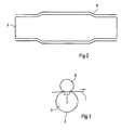
- the fibrous web 1 is guided for smoothing by an extended press nip, which is formed by a press roll 2 and a heated, cylindrical counter-roll 6.
- the press roll 2 has a flexible roll shell 3 made of plastic, which is pressed by a contact pressure element 7 with concave pressing surface to the counter roll 6 out.
- the roll shell 3 is made of polyurethane with a reinforcing thread fabric.
- the temperature resistance of the entire roll mantle 3 or at least the outside of the fibrous web 1 lying edge regions of the roll mantle 3 by the application of a cover 5 and a protective layer 4 or on the outer circumferential surface of the roll shell 3 can be increased.
- FIG. 2 shown roll shell 3 completely outside coated with a protective layer 4 of glass fabric.
- the cover is in the Figures 2 and 3 Not shown.
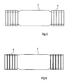
- This cover 5 is in FIG. 4 formed by a foil.
- the cover 4 from side by side wound on the roll shell 3 bands. These tapes we can in FIG. 5 flush or as in FIG. 6 be wrapped overlapping.
Landscapes
- Paper (AREA)
- Rolls And Other Rotary Bodies (AREA)
Description
- Die Erfindung betrifft eine Presswalze mit einem Walzenmantel aus Kunststoff zur Behandlung einer Papier-, Karton-, Tissue- oder einer anderen Faserstoffbahn in einer Maschine zur Herstellung und/oder Veredlung derselben, wobei die äußere Mantelfläche des Walzenmantels zumindest bereichsweise eine temperaturbestandige Abdeckung besitzt.
- Eine Walze mit diesen Merkmalen ist z.B. aus der
EP 0 959 257 A1 bekannt. - Derartige Presswalzen werden oft in Entwässerungseinrichtungen dieser Maschinen Derartige Presswalzen werden oft in Entwässerungseinrichtungen dieser Maschinen eingesetzt und bilden dabei mit einer Gegenwalze einen Pressspalt zur Entwässerung der Faserstoffbahn. Es sind auch Anwendungen in Glätteinrichtungen bekannt. In beiden Fällen sollte wegen des Kunststoffmantels die Betriebstemperatur im Pressspalt bei maximal ca. 80°C liegen.
- Die Aufgabe der Erfindung ist es die Einsatzmöglichkeiten der Presswalze zu erweitern.
- Erfindungsgemäß wurde die Aufgabe dadurch gelöst, dass die äußere Mantelfläche des Walzenmantels zumindest bereichsweise eine temperaturbeständige Abdeckung besitzt, die zumindest teilweise von einer Folie und/oder zumindest teilweise von nebeneinander gewickelten Bändern gebildet wird.
- Je nach Art des Walzenmantels oder dessen Beanspruchung können bestimmte Bereiche des Walzenmantels dabei mit einer Schutzschicht und andere mit einer Abdeckung versehen werden. Es kann jedoch zur Erhöhung der Temperaturbeständigkeit auch vorteilhaft sein, zumindest in einem Bereich die äußere Mantelfläche mit einer temperaturbeständigen Schutzschicht und darüber mit einer temperaturbeständigen Abdeckung auszustatten.
- In jedem Fall verbessert sich die Temperaturbeständigkeit des gefährdeten Bereiches, was die Einsatzmöglichkeiten der Presswalze beträchtlich erweitert. Dies gilt insbesondere für Presswalzen mit einem flexiblen Walzenmantel, der von einem Anpresselement zur Bildung eines Pressspaltes in Richtung einer vorzugsweise beheizten Gegenwalze gedrückt wird. Wegen der im Pressspalt zwischen der Presswalze und der beheizten Gegenwalze vorhandenen Faserstoffbahn und eventuell noch zusätzlich durch den Pressspalt geführter Bänder ist der Walzenmantel zumindest im mittleren Bereich vor einer thermischen Überbeanspruchung geschützt. Dies ist notwendig, da die für die Walzenmäntel verwendeten Polyurethansorten im Dauerbetrieb nicht mehr als 80 - 100 °C erreichen dürfen.
- Aber die Ränder des Walzenmantels sind nicht von der Faserstoffbahn oder einem Band abgedeckt und können so direkt mit der bis zu 350 °C heißen Gegenwalze in Kontakt kommen.
- Daher kann es zur Begrenzung des Aufwandes einerseits und einem dennoch ausreichenden thermischen Schutz andererseits von Vorteil sein, wenn die äußere Mantelfläche nur im Bereich zumindest eines, vorzugsweise beider Ränder des Walzenmantels von einer temperaturbeständigen Abdeckung, bzw. Abdeckung und Schutzchicht umgeben ist.
- Einen umfassenden thermischen Schutz des Walzenmantels erhält man jedoch, wenn die äußere Mantelfläche weitestgehend vollständig von einer temperaturbeständigen bzw. Abdeckung und Schutzchicht umgeben ist. Dies schützt den Walzenmantel dann auch bei einem Abriss der Faserstoffbahn.
- Die erhöhte Temperaturbeständigkeit erlaubt einen viel breiteren Einsatz der Presswalze in der Maschine, insbesondere bei der Entwässerung und/oder Glättung der Faserstoffbahn.
- Bei identischer Ausführung mehrerer Presswalzen in der Maschine kann so auch die Anzahl der notwendigen Reservewalzen vermindert werden.
- Um die erforderliche Temperaturbeständigkeit zu erhalten, sollte die temperaturbeständige Schutzschicht bzw. Abdeckung aus einem Material mit geringer Wärmeleitfähigkeit, insbesondere Teflon, Glasgewebe, Kapton, Mineralfasern, Keramik, Silikat, Quarz, Polymere, PEEK o. ä. oder einem Material mit guter Reflexion der Wärmestrahlung, insbesondere Aluminium oder einer Kombination davon bestehen.
- Entsprechend dem Material der temperaturbeständigen Schutzschicht kann diese zumindest teilweise auf die äußere Mantelfläche gestrichen und/oder gesprüht werden.
- Die temperaturbeständige Abdeckung ist zumindest teilweise von einer Folie und/oder von nebeneinander gewickelten Bändern gebildet werden. Dabei können die Bänder voneinander beabstandet, bündig oder überlappend mit oder ohne Steigung aufgewickelt werden.
- Nachfolgend soll die Erfindung an mehreren Ausführungsbeispielen näher erläutert werden. In der beigefügten Zeichnung zeigt:
- Figur 1:
- einen schematischen Querschnitt durch eine Pressanordnung und
- Figuren 2 bis 6:
- verschiedene Lösungen zur Erhöhung der Temperaturbeständigkeit des Walzenmantels 3.
- Gemäß
Figur 1 wird die Faserstoffbahn 1 zur Glättung durch einen verlängerten Pressspalt geführt, der von einer Presswalze 2 und einer beheizten, zylindrischen Gegenwalze 6 gebildet wird. - Die Presswalze 2 besitzt einen flexiblen Walzenmantel 3 aus Kunststoff, welcher von einem Anpresselement 7 mit konkaver Pressfläche zur Gegenwalze 6 hin gedrückt wird.
- Der Walzenmantel 3 besteht aus Polyurethan mit einem verstärkenden Fadengewebe.
- Um eine Beschädigung diese Walzenmantels 3 durch einen Kontakt mit der beheizten Gegenwalze 6 zu verhindern, wird die Temperaturbeständigkeit des gesamten Walzenmantels 3 oder zumindest der außerhalb der Faserstoffbahn 1 liegenden Randbereiche des Walzenmantels 3 durch das Aufbringen einer Abdeckung 5 und einer Schutzschicht 4 oder einer auf die äußere Mantelfläche des Walzenmantels 3 erhöht werden.
- Zum vollständigen thermischen Schutz ist der in
Figur 2 gezeigte Walzenmantel 3 vollständig außen mit einer Schutzschicht 4 aus Glasgewebe überzogen. - Im Gegensatz hierzu sind bei dem Walzenmantel gemäß
Figur 3 nur die Randbereiche des Walzenmantels 3 mit der Schutzschicht 4 überzogen. Da diese Randbereiche zumindest teilweise außerhalb der Pressfläche des Anpresselementes 7 liegen, werden diese auch nicht so stark wie der mittlere Bereich des Walzenmantels 3 verformt. Dies schont die Schutzschicht 4 und erweitert das Spektrum der einsetzbaren Materialien für die Schutzschicht 4. - Die Abdeckung ist in den
Figuren 2 und3 nicht gezeigt. - Bei den in den
Figuren 4 bis 6 dargestellten Walzenmänteln 3 wird der thermische Schutz der Randbereiche des Walzenmantels 3 nur über das Anbringen einer entsprechenden temperaturbeständigen Abdeckung 5 erreicht. - Diese Abdeckung 5 wird in
Figur 4 von einer Folie gebildet. In denFiguren 5 und 6 besteht die Abdeckung 4 aus nebeneinander auf den Walzenmantel 3 gewickelten Bändern. Diese Bänder können wir inFigur 5 bündig oder wie inFigur 6 überlappend aufgewickelt werden.
Claims (9)
- Presswalze (2) mit einem Walzenmantel (3) aus Kunststoff zur Behandlung einer Papier-, Karton-, Tissue- oder einer anderen Faserstoffbahn (1) in einer Maschine zur Herstellung und/oder Veredlung derselben, wobei die äußere Mantelfläche des Walzenmantels (3) zumindest bereichsweise eine temperaturbeständige Abdeckung (5) besitzt, dadurch gekennzeichnet, dass
die temperaturbeständige Abdeckung (5) zumindest teilweise von einer Folie und/oder zumindest teilweise von nebeneinander gewickelten Bändern gebildet wird. - Presswalze (2) nach Anspruch 1, dadurch gekennzeichnet, dass
die äußere Mantelfläche des Walzenmantels (3) zumindest bereichsweise eine temperaturbeständige Schutzschicht (4) besitzt. - Presswalze (2) nach Anspruch 1 oder 2, dadurch gekennzeichnet, dass
die äußere Mantelfläche weitestgehend vollständig von einer temperaturbeständigen Schutzschicht (4) und/oder Abdeckung (5) umgeben ist. - Presswalze (2) nach Anspruch 1 oder 2, dadurch gekennzeichnet, dass
die äußere Mantelfläche nur im Bereich zumindest eines, vorzugsweise beider Ränder des Walzenmantels (3) von einer temperaturbeständigen Schutzschicht (4) und/oder Abdeckung (5) umgeben ist. - Presswalze (2) nach einem der vorhergehenden Ansprüche, dadurch gekennzeichnet, dass
die temperaturbeständige Schutzschicht (4) bzw. Abdeckung (5) aus einem Material mit geringer Wärmeleitfähigkeit, insbesondere Teflon, Glasgewebe, Kapton, Mineralfasern, Keramik, Silikat, Quarz, Polymere, PEEK oder einem Material mit guter Reflexion der Wärmestrahlung, insbesondere Aluminium oder einer Kombination davon besteht. - Presswalze (2) nach einem der Ansprüche 2 bis 5, dadurch gekennzeichnet, dass
die temperaturbeständige Schutzschicht (4) zumindest teilweise auf die äußere Mantelfläche (5) gestrichen wird. - Presswalze (2) nach einem der Ansprüche 2 bis 6, dadurch gekennzeichnet, dass
die temperaturbeständige Schutzschicht (4) zumindest teilweise auf die äußere Mantelfläche gesprüht wird. - Presswalze (2) nach einem der vorhergehenden Ansprüche, dadurch gekennzeichnet, dass
der Walzenmantel (3) flexibel ausgebildet ist und von einem Anpresselement (7) zur Bildung eines Pressspaltes in Richtung einer vorzugsweise beheizten Gegenwalze (6) gedrückt wird. - Presswalze (2) nach Anspruch 8, dadurch gekennzeichnet, dass
der Pressspalt zur Entwässerung oder Glättung der Faserstoffbahn (1) dient.
Applications Claiming Priority (2)
| Application Number | Priority Date | Filing Date | Title |
|---|---|---|---|
| DE102004023565A DE102004023565A1 (de) | 2004-05-13 | 2004-05-13 | Presswalze |
| PCT/EP2005/051202 WO2005111303A1 (de) | 2004-05-13 | 2005-03-16 | Presswalze |
Publications (2)
| Publication Number | Publication Date |
|---|---|
| EP1747321A1 EP1747321A1 (de) | 2007-01-31 |
| EP1747321B1 true EP1747321B1 (de) | 2008-10-08 |
Family
ID=34962099
Family Applications (1)
| Application Number | Title | Priority Date | Filing Date |
|---|---|---|---|
| EP05717069A Expired - Lifetime EP1747321B1 (de) | 2004-05-13 | 2005-03-16 | Presswalze |
Country Status (6)
| Country | Link |
|---|---|
| US (1) | US8100817B2 (de) |
| EP (1) | EP1747321B1 (de) |
| JP (1) | JP4807756B2 (de) |
| AT (1) | ATE410547T1 (de) |
| DE (2) | DE102004023565A1 (de) |
| WO (1) | WO2005111303A1 (de) |
Families Citing this family (3)
| Publication number | Priority date | Publication date | Assignee | Title |
|---|---|---|---|---|
| FI20085140L (fi) * | 2008-02-18 | 2009-08-19 | Metso Paper Inc | Kuiturainakoneen tela ja menetelmä kuiturainakoneen telan valmistamiseksi |
| DE102009009186B4 (de) * | 2009-02-16 | 2011-04-21 | Airbus Operations Gmbh | Anpressvorrichtung zum Anpressen von faserverstärkten thermoplastischen Materialien und Faseranordnungsvorrichtung |
| US9505206B1 (en) | 2016-03-15 | 2016-11-29 | Harper Corporation Of America | Cladless anilox sleeve for use in flexographic printing |
Family Cites Families (19)
| Publication number | Priority date | Publication date | Assignee | Title |
|---|---|---|---|---|
| US649145A (en) * | 1900-01-16 | 1900-05-08 | Martin W Thrush | Pneumatic roll. |
| US2678474A (en) * | 1949-03-23 | 1954-05-18 | Textile Engineering Corp | Top roll for textile drawing mechanisms |
| US2775793A (en) * | 1951-12-08 | 1957-01-01 | Louis M Cotchett | Top roll for drawing mechanism |
| JPS4739869B1 (de) * | 1969-09-19 | 1972-10-07 | ||
| US3812561A (en) * | 1973-01-15 | 1974-05-28 | W Lundgren | Temple roll |
| JPS57118898A (en) * | 1981-01-14 | 1982-07-23 | Kinyoushiya:Kk | Roll for press |
| JPH01260092A (ja) * | 1987-12-30 | 1989-10-17 | Yamauchi Corp | 硬質ロールの製造法 |
| DE4128655C2 (de) * | 1991-08-29 | 1995-06-14 | Escher Wyss Gmbh | Verfahren und Vorrichtung zur Durchmesserprofilbeeinflussung im Endbereich beheizter Walzen |
| JPH06235183A (ja) * | 1993-02-04 | 1994-08-23 | Kobayashi Seisakusho:Kk | プレスロール装置とその使用方法 |
| US5499093A (en) * | 1993-06-18 | 1996-03-12 | Xeikon Nv | Electrostatographic single-pass multiple station printer with register control |
| DE4431648C1 (de) * | 1994-09-06 | 1996-01-18 | Koenig & Bauer Albert Ag | Andrückwalze für das Andrücken einer laufenden Warenbahn |
| US5785636A (en) * | 1995-10-12 | 1998-07-28 | Beloit Technologies, Inc. | Composite roll shell |
| FI2640U1 (fi) * | 1996-03-22 | 1996-11-22 | Valmet Corp | Tela, erityisesti soft- tai superkalanterin tela |
| US6409645B1 (en) * | 1997-06-13 | 2002-06-25 | Sw Paper Inc. | Roll cover |
| DE19822531B4 (de) * | 1998-05-19 | 2006-11-30 | Voith Patent Gmbh | Kalanderwalze |
| FI110273B (fi) * | 2001-05-07 | 2002-12-31 | Metso Paper Inc | Järjestely paperikoneen tai sellukoneen telan reuna-alueen jäähdyttämiseksi |
| US6780287B2 (en) * | 2001-06-28 | 2004-08-24 | Ichikawa Co., Ltd. | Belt for calendering |
| DE20220685U1 (de) * | 2001-08-14 | 2003-12-24 | Eduard Küsters, Maschinenfabrik, GmbH & Co. KG | Vorrichtung zum Bilden eines Langspalts |
| WO2003102700A1 (en) * | 2002-06-03 | 2003-12-11 | Fuji Xerox Co., Ltd. | Heat roller and heat roller manufacturing method |
-
2004
- 2004-05-13 DE DE102004023565A patent/DE102004023565A1/de not_active Withdrawn
-
2005
- 2005-03-16 DE DE502005005625T patent/DE502005005625D1/de not_active Expired - Lifetime
- 2005-03-16 WO PCT/EP2005/051202 patent/WO2005111303A1/de not_active Ceased
- 2005-03-16 EP EP05717069A patent/EP1747321B1/de not_active Expired - Lifetime
- 2005-03-16 JP JP2007512140A patent/JP4807756B2/ja not_active Expired - Fee Related
- 2005-03-16 AT AT05717069T patent/ATE410547T1/de not_active IP Right Cessation
-
2006
- 2006-11-10 US US11/558,733 patent/US8100817B2/en not_active Expired - Fee Related
Also Published As
| Publication number | Publication date |
|---|---|
| DE502005005625D1 (de) | 2008-11-20 |
| ATE410547T1 (de) | 2008-10-15 |
| US20070066469A1 (en) | 2007-03-22 |
| EP1747321A1 (de) | 2007-01-31 |
| JP2007537366A (ja) | 2007-12-20 |
| WO2005111303A1 (de) | 2005-11-24 |
| US8100817B2 (en) | 2012-01-24 |
| JP4807756B2 (ja) | 2011-11-02 |
| DE102004023565A1 (de) | 2005-12-08 |
Similar Documents
| Publication | Publication Date | Title |
|---|---|---|
| EP2820187B1 (de) | Maschine zur herstellung einer faserstoffbahn | |
| DE102004023565A1 (de) | Presswalze | |
| EP3662107B1 (de) | Pressmantel und dessen verwendung sowie presswalze und schuhpresse | |
| EP1041198A1 (de) | Elastische Walze und Verfahren zum Herstellen einer solchen | |
| EP1959052B1 (de) | Schuhpresswalze | |
| EP1634994B1 (de) | Kalanderanordnung | |
| EP1749926B1 (de) | Pressanordnung | |
| WO2020025210A1 (de) | Pressmantel, dessen verwendung sowie presswalze und schuhpresse | |
| EP1333121B1 (de) | Kalander und Verfahren zum Betreiben eines Kalanders | |
| EP1992736B1 (de) | Pressanordnung | |
| EP1285990B1 (de) | Vorrichtung zum Bilden eines Langspalts | |
| EP3853412A1 (de) | Pressmantel, dessen verwendung sowie presswalze, schuhpresse und verwendung eines polyuretehans zur herstellung eines pressmantels | |
| EP3830335B1 (de) | Pressmantel, dessen verwendung sowie presswalze und schuhpresse | |
| EP3786358B1 (de) | Walze für eine papiermaschine und deren verwendung | |
| DE10148263A1 (de) | Verfahren zur Herstellung eines Walzenbezuges | |
| EP0745725A2 (de) | Walzenpresse | |
| EP2314763B1 (de) | Vorrichtung zur Behandlung einer Faserstoffbahn | |
| EP1333124B1 (de) | Verfahren und Vorrichtung zum Herstellen einer Papierbahn | |
| DE102018122781A1 (de) | Pressmantel, dessen Verwendung sowie Presswalze und Schuhpresse | |
| EP1394320B1 (de) | Nasspressenanordnung | |
| AT513424B1 (de) | Anlage zur Wärmeübertragung in einer Faserbahnmaschine, Oberflächenbearbeitungsvorrichtung zur Bearbeitung der Faserbahnoberfläche und Trockenpartie einer Faserbahnmaschine | |
| DE102005041223A1 (de) | Trockenanordnung | |
| DE102004026411A1 (de) | Presswalze | |
| EP1559831B1 (de) | Breitnip-Kalander | |
| EP1785524A1 (de) | Anordnung zum Glätten einer Faserstoffbahn |
Legal Events
| Date | Code | Title | Description |
|---|---|---|---|
| PUAI | Public reference made under article 153(3) epc to a published international application that has entered the european phase |
Free format text: ORIGINAL CODE: 0009012 |
|
| 17P | Request for examination filed |
Effective date: 20061017 |
|
| AK | Designated contracting states |
Kind code of ref document: A1 Designated state(s): AT BE BG CH CY CZ DE DK EE ES FI FR GB GR HU IE IS IT LI LT LU MC NL PL PT RO SE SI SK TR |
|
| 17Q | First examination report despatched |
Effective date: 20070611 |
|
| DAX | Request for extension of the european patent (deleted) | ||
| GRAP | Despatch of communication of intention to grant a patent |
Free format text: ORIGINAL CODE: EPIDOSNIGR1 |
|
| GRAS | Grant fee paid |
Free format text: ORIGINAL CODE: EPIDOSNIGR3 |
|
| GRAA | (expected) grant |
Free format text: ORIGINAL CODE: 0009210 |
|
| AK | Designated contracting states |
Kind code of ref document: B1 Designated state(s): AT BE BG CH CY CZ DE DK EE ES FI FR GB GR HU IE IS IT LI LT LU MC NL PL PT RO SE SI SK TR |
|
| REG | Reference to a national code |
Ref country code: GB Ref legal event code: FG4D Free format text: NOT ENGLISH |
|
| REG | Reference to a national code |
Ref country code: CH Ref legal event code: EP |
|
| REG | Reference to a national code |
Ref country code: IE Ref legal event code: FG4D Free format text: LANGUAGE OF EP DOCUMENT: GERMAN |
|
| REF | Corresponds to: |
Ref document number: 502005005625 Country of ref document: DE Date of ref document: 20081120 Kind code of ref document: P |
|
| REG | Reference to a national code |
Ref country code: SE Ref legal event code: TRGR |
|
| PG25 | Lapsed in a contracting state [announced via postgrant information from national office to epo] |
Ref country code: SI Free format text: LAPSE BECAUSE OF FAILURE TO SUBMIT A TRANSLATION OF THE DESCRIPTION OR TO PAY THE FEE WITHIN THE PRESCRIBED TIME-LIMIT Effective date: 20081008 |
|
| NLV1 | Nl: lapsed or annulled due to failure to fulfill the requirements of art. 29p and 29m of the patents act | ||
| PG25 | Lapsed in a contracting state [announced via postgrant information from national office to epo] |
Ref country code: BG Free format text: LAPSE BECAUSE OF FAILURE TO SUBMIT A TRANSLATION OF THE DESCRIPTION OR TO PAY THE FEE WITHIN THE PRESCRIBED TIME-LIMIT Effective date: 20090108 Ref country code: LT Free format text: LAPSE BECAUSE OF FAILURE TO SUBMIT A TRANSLATION OF THE DESCRIPTION OR TO PAY THE FEE WITHIN THE PRESCRIBED TIME-LIMIT Effective date: 20081008 Ref country code: ES Free format text: LAPSE BECAUSE OF FAILURE TO SUBMIT A TRANSLATION OF THE DESCRIPTION OR TO PAY THE FEE WITHIN THE PRESCRIBED TIME-LIMIT Effective date: 20090119 |
|
| PG25 | Lapsed in a contracting state [announced via postgrant information from national office to epo] |
Ref country code: NL Free format text: LAPSE BECAUSE OF FAILURE TO SUBMIT A TRANSLATION OF THE DESCRIPTION OR TO PAY THE FEE WITHIN THE PRESCRIBED TIME-LIMIT Effective date: 20081008 Ref country code: PT Free format text: LAPSE BECAUSE OF FAILURE TO SUBMIT A TRANSLATION OF THE DESCRIPTION OR TO PAY THE FEE WITHIN THE PRESCRIBED TIME-LIMIT Effective date: 20090218 Ref country code: PL Free format text: LAPSE BECAUSE OF FAILURE TO SUBMIT A TRANSLATION OF THE DESCRIPTION OR TO PAY THE FEE WITHIN THE PRESCRIBED TIME-LIMIT Effective date: 20081008 Ref country code: IS Free format text: LAPSE BECAUSE OF FAILURE TO SUBMIT A TRANSLATION OF THE DESCRIPTION OR TO PAY THE FEE WITHIN THE PRESCRIBED TIME-LIMIT Effective date: 20090208 |
|
| REG | Reference to a national code |
Ref country code: IE Ref legal event code: FD4D |
|
| PG25 | Lapsed in a contracting state [announced via postgrant information from national office to epo] |
Ref country code: RO Free format text: LAPSE BECAUSE OF FAILURE TO SUBMIT A TRANSLATION OF THE DESCRIPTION OR TO PAY THE FEE WITHIN THE PRESCRIBED TIME-LIMIT Effective date: 20081008 Ref country code: DK Free format text: LAPSE BECAUSE OF FAILURE TO SUBMIT A TRANSLATION OF THE DESCRIPTION OR TO PAY THE FEE WITHIN THE PRESCRIBED TIME-LIMIT Effective date: 20081008 Ref country code: IE Free format text: LAPSE BECAUSE OF FAILURE TO SUBMIT A TRANSLATION OF THE DESCRIPTION OR TO PAY THE FEE WITHIN THE PRESCRIBED TIME-LIMIT Effective date: 20081008 Ref country code: EE Free format text: LAPSE BECAUSE OF FAILURE TO SUBMIT A TRANSLATION OF THE DESCRIPTION OR TO PAY THE FEE WITHIN THE PRESCRIBED TIME-LIMIT Effective date: 20081008 |
|
| PLBE | No opposition filed within time limit |
Free format text: ORIGINAL CODE: 0009261 |
|
| STAA | Information on the status of an ep patent application or granted ep patent |
Free format text: STATUS: NO OPPOSITION FILED WITHIN TIME LIMIT |
|
| PG25 | Lapsed in a contracting state [announced via postgrant information from national office to epo] |
Ref country code: CZ Free format text: LAPSE BECAUSE OF FAILURE TO SUBMIT A TRANSLATION OF THE DESCRIPTION OR TO PAY THE FEE WITHIN THE PRESCRIBED TIME-LIMIT Effective date: 20081008 Ref country code: IT Free format text: LAPSE BECAUSE OF FAILURE TO SUBMIT A TRANSLATION OF THE DESCRIPTION OR TO PAY THE FEE WITHIN THE PRESCRIBED TIME-LIMIT Effective date: 20081008 |
|
| 26N | No opposition filed |
Effective date: 20090709 |
|
| BERE | Be: lapsed |
Owner name: VOITH PATENT G.M.B.H. Effective date: 20090331 |
|
| PG25 | Lapsed in a contracting state [announced via postgrant information from national office to epo] |
Ref country code: SK Free format text: LAPSE BECAUSE OF FAILURE TO SUBMIT A TRANSLATION OF THE DESCRIPTION OR TO PAY THE FEE WITHIN THE PRESCRIBED TIME-LIMIT Effective date: 20081008 |
|
| PG25 | Lapsed in a contracting state [announced via postgrant information from national office to epo] |
Ref country code: MC Free format text: LAPSE BECAUSE OF NON-PAYMENT OF DUE FEES Effective date: 20090331 |
|
| REG | Reference to a national code |
Ref country code: CH Ref legal event code: PL |
|
| REG | Reference to a national code |
Ref country code: FR Ref legal event code: ST Effective date: 20091130 |
|
| PG25 | Lapsed in a contracting state [announced via postgrant information from national office to epo] |
Ref country code: CH Free format text: LAPSE BECAUSE OF NON-PAYMENT OF DUE FEES Effective date: 20090331 Ref country code: LI Free format text: LAPSE BECAUSE OF NON-PAYMENT OF DUE FEES Effective date: 20090331 |
|
| PG25 | Lapsed in a contracting state [announced via postgrant information from national office to epo] |
Ref country code: BE Free format text: LAPSE BECAUSE OF NON-PAYMENT OF DUE FEES Effective date: 20090331 |
|
| PG25 | Lapsed in a contracting state [announced via postgrant information from national office to epo] |
Ref country code: FR Free format text: LAPSE BECAUSE OF NON-PAYMENT OF DUE FEES Effective date: 20091123 |
|
| PGFP | Annual fee paid to national office [announced via postgrant information from national office to epo] |
Ref country code: AT Payment date: 20100311 Year of fee payment: 6 |
|
| PG25 | Lapsed in a contracting state [announced via postgrant information from national office to epo] |
Ref country code: GR Free format text: LAPSE BECAUSE OF FAILURE TO SUBMIT A TRANSLATION OF THE DESCRIPTION OR TO PAY THE FEE WITHIN THE PRESCRIBED TIME-LIMIT Effective date: 20090109 |
|
| PGFP | Annual fee paid to national office [announced via postgrant information from national office to epo] |
Ref country code: SE Payment date: 20100312 Year of fee payment: 6 |
|
| PG25 | Lapsed in a contracting state [announced via postgrant information from national office to epo] |
Ref country code: LU Free format text: LAPSE BECAUSE OF NON-PAYMENT OF DUE FEES Effective date: 20090316 |
|
| PGFP | Annual fee paid to national office [announced via postgrant information from national office to epo] |
Ref country code: FI Payment date: 20110314 Year of fee payment: 7 |
|
| PG25 | Lapsed in a contracting state [announced via postgrant information from national office to epo] |
Ref country code: HU Free format text: LAPSE BECAUSE OF FAILURE TO SUBMIT A TRANSLATION OF THE DESCRIPTION OR TO PAY THE FEE WITHIN THE PRESCRIBED TIME-LIMIT Effective date: 20090409 |
|
| PGFP | Annual fee paid to national office [announced via postgrant information from national office to epo] |
Ref country code: DE Payment date: 20110325 Year of fee payment: 7 Ref country code: GB Payment date: 20110321 Year of fee payment: 7 |
|
| PG25 | Lapsed in a contracting state [announced via postgrant information from national office to epo] |
Ref country code: TR Free format text: LAPSE BECAUSE OF FAILURE TO SUBMIT A TRANSLATION OF THE DESCRIPTION OR TO PAY THE FEE WITHIN THE PRESCRIBED TIME-LIMIT Effective date: 20081008 |
|
| PG25 | Lapsed in a contracting state [announced via postgrant information from national office to epo] |
Ref country code: CY Free format text: LAPSE BECAUSE OF FAILURE TO SUBMIT A TRANSLATION OF THE DESCRIPTION OR TO PAY THE FEE WITHIN THE PRESCRIBED TIME-LIMIT Effective date: 20081008 |
|
| REG | Reference to a national code |
Ref country code: SE Ref legal event code: EUG |
|
| PG25 | Lapsed in a contracting state [announced via postgrant information from national office to epo] |
Ref country code: AT Free format text: LAPSE BECAUSE OF NON-PAYMENT OF DUE FEES Effective date: 20110316 |
|
| PG25 | Lapsed in a contracting state [announced via postgrant information from national office to epo] |
Ref country code: FI Free format text: LAPSE BECAUSE OF NON-PAYMENT OF DUE FEES Effective date: 20120316 |
|
| GBPC | Gb: european patent ceased through non-payment of renewal fee |
Effective date: 20120316 |
|
| PG25 | Lapsed in a contracting state [announced via postgrant information from national office to epo] |
Ref country code: GB Free format text: LAPSE BECAUSE OF NON-PAYMENT OF DUE FEES Effective date: 20120316 |
|
| REG | Reference to a national code |
Ref country code: DE Ref legal event code: R119 Ref document number: 502005005625 Country of ref document: DE Effective date: 20121002 |
|
| PG25 | Lapsed in a contracting state [announced via postgrant information from national office to epo] |
Ref country code: SE Free format text: LAPSE BECAUSE OF NON-PAYMENT OF DUE FEES Effective date: 20110317 |
|
| PG25 | Lapsed in a contracting state [announced via postgrant information from national office to epo] |
Ref country code: DE Free format text: LAPSE BECAUSE OF NON-PAYMENT OF DUE FEES Effective date: 20121002 |