EP1746944B1 - Chirurgischer pneumatischer motor zur verwendung mit mrt - Google Patents
Chirurgischer pneumatischer motor zur verwendung mit mrt Download PDFInfo
- Publication number
- EP1746944B1 EP1746944B1 EP05725045.8A EP05725045A EP1746944B1 EP 1746944 B1 EP1746944 B1 EP 1746944B1 EP 05725045 A EP05725045 A EP 05725045A EP 1746944 B1 EP1746944 B1 EP 1746944B1
- Authority
- EP
- European Patent Office
- Prior art keywords
- housing
- motor
- spindle
- vane
- bearings
- Prior art date
- Legal status (The legal status is an assumption and is not a legal conclusion. Google has not performed a legal analysis and makes no representation as to the accuracy of the status listed.)
- Expired - Lifetime
Links
Images







Classifications
-
- F—MECHANICAL ENGINEERING; LIGHTING; HEATING; WEAPONS; BLASTING
- F01—MACHINES OR ENGINES IN GENERAL; ENGINE PLANTS IN GENERAL; STEAM ENGINES
- F01C—ROTARY-PISTON OR OSCILLATING-PISTON MACHINES OR ENGINES
- F01C1/00—Rotary-piston machines or engines
- F01C1/30—Rotary-piston machines or engines having the characteristics covered by two or more groups F01C1/02, F01C1/08, F01C1/22, F01C1/24 or having the characteristics covered by one of these groups together with some other type of movement between co-operating members
- F01C1/34—Rotary-piston machines or engines having the characteristics covered by two or more groups F01C1/02, F01C1/08, F01C1/22, F01C1/24 or having the characteristics covered by one of these groups together with some other type of movement between co-operating members having the movement defined in group F01C1/08 or F01C1/22 and relative reciprocation between the co-operating members
- F01C1/344—Rotary-piston machines or engines having the characteristics covered by two or more groups F01C1/02, F01C1/08, F01C1/22, F01C1/24 or having the characteristics covered by one of these groups together with some other type of movement between co-operating members having the movement defined in group F01C1/08 or F01C1/22 and relative reciprocation between the co-operating members with vanes reciprocating with respect to the inner member
-
- A—HUMAN NECESSITIES
- A61—MEDICAL OR VETERINARY SCIENCE; HYGIENE
- A61B—DIAGNOSIS; SURGERY; IDENTIFICATION
- A61B17/00—Surgical instruments, devices or methods
- A61B17/16—Instruments for performing osteoclasis; Drills or chisels for bones; Trepans
- A61B17/1613—Component parts
- A61B17/1628—Motors; Power supplies
-
- A—HUMAN NECESSITIES
- A61—MEDICAL OR VETERINARY SCIENCE; HYGIENE
- A61B—DIAGNOSIS; SURGERY; IDENTIFICATION
- A61B17/00—Surgical instruments, devices or methods
- A61B17/32—Surgical cutting instruments
- A61B17/320016—Endoscopic cutting instruments, e.g. arthroscopes, resectoscopes
- A61B17/32002—Endoscopic cutting instruments, e.g. arthroscopes, resectoscopes with continuously rotating, oscillating or reciprocating cutting instruments
-
- F—MECHANICAL ENGINEERING; LIGHTING; HEATING; WEAPONS; BLASTING
- F01—MACHINES OR ENGINES IN GENERAL; ENGINE PLANTS IN GENERAL; STEAM ENGINES
- F01C—ROTARY-PISTON OR OSCILLATING-PISTON MACHINES OR ENGINES
- F01C21/00—Component parts, details or accessories not provided for in groups F01C1/00 - F01C20/00
- F01C21/06—Heating; Cooling; Heat insulation
-
- A—HUMAN NECESSITIES
- A61—MEDICAL OR VETERINARY SCIENCE; HYGIENE
- A61B—DIAGNOSIS; SURGERY; IDENTIFICATION
- A61B17/00—Surgical instruments, devices or methods
- A61B2017/00535—Surgical instruments, devices or methods pneumatically or hydraulically operated
- A61B2017/00544—Surgical instruments, devices or methods pneumatically or hydraulically operated pneumatically
-
- A—HUMAN NECESSITIES
- A61—MEDICAL OR VETERINARY SCIENCE; HYGIENE
- A61B—DIAGNOSIS; SURGERY; IDENTIFICATION
- A61B17/00—Surgical instruments, devices or methods
- A61B2017/00831—Material properties
- A61B2017/00902—Material properties transparent or translucent
- A61B2017/00911—Material properties transparent or translucent for fields applied by a magnetic resonance imaging system
-
- F—MECHANICAL ENGINEERING; LIGHTING; HEATING; WEAPONS; BLASTING
- F04—POSITIVE - DISPLACEMENT MACHINES FOR LIQUIDS; PUMPS FOR LIQUIDS OR ELASTIC FLUIDS
- F04C—ROTARY-PISTON, OR OSCILLATING-PISTON, POSITIVE-DISPLACEMENT MACHINES FOR LIQUIDS; ROTARY-PISTON, OR OSCILLATING-PISTON, POSITIVE-DISPLACEMENT PUMPS
- F04C2240/00—Components
- F04C2240/50—Bearings
-
- F—MECHANICAL ENGINEERING; LIGHTING; HEATING; WEAPONS; BLASTING
- F05—INDEXING SCHEMES RELATING TO ENGINES OR PUMPS IN VARIOUS SUBCLASSES OF CLASSES F01-F04
- F05C—INDEXING SCHEME RELATING TO MATERIALS, MATERIAL PROPERTIES OR MATERIAL CHARACTERISTICS FOR MACHINES, ENGINES OR PUMPS OTHER THAN NON-POSITIVE-DISPLACEMENT MACHINES OR ENGINES
- F05C2251/00—Material properties
- F05C2251/12—Magnetic properties
- F05C2251/125—Magnetic properties non-magnetic
Definitions
- This invention relates to pneumatic motors for use by surgeons for performing surgical procedures that are typical in general surgery, neurosurgery, endoscopic, arthroscopic and the like and more particularly to an improved pneumatic motor that has utility in connection with an MRI process.
- MRI magnetic resonance imaging machine
- the MRI utilizes an external magnetic field that is created by a series of electro-magnets in a scanner that serve to excite the hydrogen atoms in the body of the patient being analyzed. These hydrogen atoms create radio signals which are read by a computer and converted into detailed images.
- This invention addresses this problem by providing a pneumatic motor that is capable of being used in the presence of an MRI machine without adversely affecting the magnetic field generated thereby and hence, is incapable of adversely affecting the image generated by this machine.
- this invention also provides improvements to heretofore known pneumatic surgical motors notwithstanding the fact that these prior art motors are not usable in an MRI environment.
- this invention applies to pneumatic surgical motors that can be used with MRI machines and to those motors that cannot be used with MRI machines.
- a motor that can be used with an MRI machine can also be used where an MRI machine is not being used.
- This invention contemplates the improvement of heretofore known pneumatic surgical motors including the pneumatic surgical motors being manufactured by and sold by the assignee and all are well known in the medical industry as the Black Max, the Micro Max and the Micro Max Plus. While these motors mentioned immediately above in this paragraph are not capable of use with MRI machines, this invention provides all of the features that are associated with these motors, but does so with an improved surgical instrument.
- the Black Max is a heavy duty motor that is more powerful and larger than the other two motors, but is heavier, hotter, noisier and vibrates more than these other motors.
- the Micro Max, supra was developed to reduce the size, noise, vibration and heat and to be essentially more gentle for use by the surgeon and likewise, has developed a niche in the industry.
- the power is reduced.
- this motor for some medical procedures does not meet the needs of the surgeons because it lacked the necessary power which gave rise to the Micro Max Plus motor, which, again, has more power than the Micro Max but, yet, less power than the Black Max.
- the Micro Max Plus falls in the category of being more gentle for use by the surgeon but again, because of the increased power, heat, vibrations and weight of the Micro Max Plus (higher than the Micro Max but still lower than the Black Max) it, likewise, has gained a niche in the industry.
- the outside diameter of all of the well known commercially available pneumatic surgical motors including the ones noted in the above paragraphs are substantially equal and include a rotor that Is driven by pressurized air for rotating a spindle that is rotatably supported by bearings in an outer housing that serves as the handle of the motor. All of these motors also Include in some form or another the necessary seals, anti-rotational device, inlet and outlet for the pressurized air and means for lubricating the bearings and their support structures or internal housings.
- the following features may contribute to the overall improvements to the motor.
- the invention provides a pneumatic surgical motor capable of being used In the presence of an MRI machine as claimed in claim 1.
- a second aspect of the invention provides a pneumatic surgical motor as claimed in claim 4.
- the present invention may provide a surgical motor for powering drills, burrs and the like for use in surgical procedure where an MRI machine Is being utilized and an improved surgical motor.
- an improved surgical motor having spindle bearings with alternating metal and plastic needles, zero velocity axial thrust support for minimizing wear and lower heat, laminated seal for lower velocity and lower heat, increased vane working surface for augmenting the power of the motor, angled slots formed on the spindle to enhance power of the motor and minimizes wear by discretely, spindle end thrust bearings to prevent metal-to-metal on outward exerted axial thrust, exhaust holes formed on the cylinder discharging compressed air are judiciously located to minimize wear on the edge of the vane by distributing contact area evenly and to reduce noise of the motor, cylindrical holes for the input air to the vane motor so as to increase air volume, cylinder crescent seal to increase the effectiveness of the spindle-to-cylinder gap seal and minimize lubrication requirements, stainless steel housing and isolation peek sleeve, increased power cycle by increasing the circumferential spacing between the vane motor's inlet and outlet ports, noise reduction by criss-crossing outlet air flow, slots in the cylinder formed
- this invention is usable with an MRI machine without jeopardizing the magnetism associated with this machine, it will be appreciated by one skilled in this art that this invention can be utilized in other environment and where it is not intended to be used for MRI applications, it could be fabricated from different materials which typically would be less expensive or have other advantages.
- FIGs. 1 and 2 show the motor generally indicated by reference numeral 50 and the attachment mechanism which is generally illustrated by reference numeral 52 including chuck means for removably attaching the attachment and for removably attaching the drill bit, burr and the various surgical instruments used with the motor (not shown).
- reference numeral 52 shows the motor generally indicated by reference numeral 50 and the attachment mechanism which is generally illustrated by reference numeral 52 including chuck means for removably attaching the attachment and for removably attaching the drill bit, burr and the various surgical instruments used with the motor (not shown).
- the elements In the attachment mechanism 52 are well known for the sake of simplicity and convenience the details thereof are omitted hear from and for further details reference should be made to the Black Max, the Micro Max and the Micro Max Plus surgical motors.
- a surgical motor comprises spindle 1, vane 2, motor cylinder 3, pin 4, bearing housing 5, thrust washer 6, small Teflon seal 7, pin 8, torion pin 9, pin retainer 10, seal housing 11, seal housing cap 12, O-ring 13, spindle extension 14, safety spacer 16, small pin 16, safety pin 17, spring 18, retaining ball 19, key ring 20, key ring cap 21, bearing spacer 22, back plate bearing 23, bearing adjusting screw 24, O-ring 25, Pin 26, motor adapter 27, dowel pin 28, ceramic ball 29, motor housing 30, O-ring 31, tube housing 32, lock spacer 33, set screw 34, housing pin 37, O-ring 38, snap ring 39 and sleeve 40.
- Power is developed by the vane motor generally illustrated by reference numeral 53 as comprising cylinder 3 and spindle 1.
- the spindle having diametrically opposed stud shafts 61 and 63 extending on opposite ends thereof and supported by suitable bearings (5,23) carries a plurality of vanes 2 spaced around the circumference and the cylinder 3 includes a plurality of inlet holes and discharge holes that direct pressurized air into the Interior of cylinder 3 to impinge on the vanes so as to rotate the spindle for driving the output shaft and judiciously discharging the exhaust air as will be described in detail herein below.
- the motor cylinder 3 made from a non-magnetic stainless steel material, such as 316 SST and which is a cylindrical element with a single row of a plurality of spindle inlet holes 56 that are axially spaced and which receives the pressurized air through a central inlet opening 59 that flows the air toward the inner surface of the housing 30 into the axial slot 58.
- a non-magnetic stainless steel material such as 316 SST
- spindle inlet holes 56 that are axially spaced and which receives the pressurized air through a central inlet opening 59 that flows the air toward the inner surface of the housing 30 into the axial slot 58.
- the rear or aft end of the motor is on the left hand side and the fore end of the motor is on the right hand side.
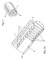
- a plurality of axially spaced circumferential slots or grooves 60 are formed on the fore end of cylinder 3 immediate forward of the blocked off portion 69.
- spindle inlet holes are drilled holes and cylindrical in shape and are not slots as is the heretofore accepted method of providing inlet openings to the spindle.
- the air flowing through the circumferential slots 60 serve to cool the cylinder and the portion of air flowing past the cylinder 3 and back into the cylinder serve to cool the bearings which will be described in further detail hereinbelow.
- the exhaust air flowing out of holes 66 is directed toward the rear of the motor, i.e. toward the left end as viewed in this Fig. 3B and then discharged out of cylinder 3 as will be detailed in the description to follow.
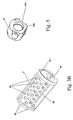
- Fig. 3B illustrates the discharge holes 66 judiciously disposed in cylinder 3 and serve as the exhaust outlet for spindle 1. These holes are arranged so that the vane passing thereunder will virtually see an even contact of the cylinder surface so as to eliminate the uneven wearing of the vane's outer edge. Because of the arrangement of the discharge ports in heretofore known surgical motors, there exhibited an unevenness of wear on the outer edge of the vanes. To avoid this unevenness as is illustrated in Fig.
- the cord H at the right hand side is selected and it equals the radius R.
- the distance between the center line of hole 66A and this cord H establishes the unit U (the unit of measurement) which is used for the measurement to set the relative distance of all other cords within a column.
- Each space between cords (vertical lines) equals 1 ⁇ 2 the unit of measurement U.
- the spacing of rows is not critical save that the adjacent hole in a given row that does not overlap the adjacent hole.
- the hole 66B is established by aligning chords H of 66B with chords H of 66A and 66A1.
- the next row 66C is established by aligning the chord G with the centerline F of 66A.
- Row 66C1 is established by aligning centerline F of 66C1 with chord G of 66A1.
- the next displacement over the holes 66A and 66C is equal to G and F.
- the next displacement of vane 2 is over the holes in 66A, 66B and 66C and this is equal to chords H, H and G.
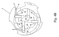
- the spindle 1 is an elongated cylinder body that includes a pair of diametrically disposed stub shafts 61 and 63 made from a non-magnetic stainless steel material, such as 316 SST and that Is eccentrically mounted inside cylinder 3.
- Spindle 1 includes four axial slots 60 circumferentially spaced and off-set from the spindle center line.
- the vanes made from a plastic material such as Vespel® are mounted in slots 80 for reciprocal motion and rotate within cylinder 3 to generate power in the well known vane motor manner.
- this spindle differs from prior art spindles not only because of the off set of slots 80 but it is slotted to increase the power thereof.
- a series of cut out are Introduced to spindle 1.
- the three axial grooves 82 adjacent to the working face of each of the vanes 2 increase the working area of the vane' s working surface.
- the arrows A represent the pressurized air impinging on the working or power face 83 of the vane 2.
- circumferentially spaced slots 84 are formed in the peripheral surface of spindle 1 and serve as a shoulder where the Inlet pressurized air impinges on the power face 85 to also, increase the power of the spindle and hence, the overall power of the surgical motor.
- the slots 80 are off-set from the spindle center line CL. This serves to reduce the friction on the vanes as they return into the slots after the power cycle of the vanes. Since the spindle is rotating at approximately 1.3 kHz (80,000 RPM) it creates a significant centrifugal force which tends to have its line of action toward the center line. The offset reduces the effect of the centrifugal force and significantly reduces the force that the vane needs to overcome when it reciprocates back into the slot 80.
- Power generated by the vane motor is further increased by increasing the vane displacement by locating the discharge port further away from the inlet port.
- the displacement between the inlet hole spans almost 180 degrees. In heretofore vane motors the span is closer. This is due to the fact that the inlets are now drilled holes and lesser number of discharge holes span a column of holes.
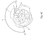
- Additional power is generated in accordance with embodiments of this invention by judiciously orienting the inlet holes 56 further away from the pinch point in proximity to the working face of the vanes 2-
- the location of the air inlet hole is where the surfaces of the spindle and cylinder are close to the pinch point and the space between these surfaces is minimal compared to re-locating the holes 56 further away from the pinch point.
- Arrows A and B illustrate this feature. Obviously, the distance of the arrows A are closer to each other in comparison to the distance between the arrows B. The increase flow to the vane working surface adds to the power generated by the spindle.
- the housing 30 encasing the components of the motor Is made from a non-magnetic material such as commercially available 316 or 317 stainless steel. All the other metallic parts are likewise made from the same material.
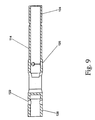
- the spindle 1 is supported on either end by needle bearings 8 and 9 mounted in the pin retainers 10 which are alternately made up with 316 stainless steel pins or needles and commercially available Torlon® pins or needles.
- needle bearings 8 and 9 are circumferentially stacked in the back plate bearing 23 and the bearing housing 5 each of which include a cavity for holding grease. These cavities and bearings are suitably sealed.
- the wear of the seal 7 is reduced by axially stacking a plurality of seal discs 131 preferably made from Teflon® material. Since the end discs are adjacent to non moving parts, they will have a tendency not to rotate. The discs in-between, however, will randomly rotate by virtue of the rotating shaft. Since each disc rotates at a different speed the seals will exhibit less wear and hence, contribute to the long life of the motor as well as effectively providing an improved seal for sealing the grease in the bearing housing.
- the thrust generated by the surgical motor when the surgical procedure is being performed is taken up by the thrust washer 6 suitably made from commercially available Delrin® AF and the ball 29 suitably made from a commercially available ceramic material.
- the ball 29 is located in coincidence with the center line of the motor so that it doesn't rotate. This assures that the wear thereof Is minimal and it doesn't generate heat.
- the thrust washers 6 sandwich the spindle 1 so that all the thrust loads are taken up by the thrust ball 29 and thrust washers 6. By virtue of this design the only loads that are seen by the needle bearings are the radial loads.
- the outer surface 94 of the housing 30 is serrated or threaded and lies underneath an outer sleeve made from a suitable plastic material. Since this is the location where the surgeon holds onto the surgical motor when performing a surgical procedure such as burring or drilling, the serrations or threads and the material selected maintain a tolerable temperature for ease of handling this instrument.
- the spindle extension 14 which connects at one end 120 to the spindle and includes the diametrically drilled holes 122 that receive a pin for connecting to the chuck assembly.
- the central bore 124 on the right hand end of the spindle extension 14 is adapted to receive the end of the cutter shaft (not shown) where the retaining balls 19 (Fig- 2) fit into the holes 126 for locking the cutter to the spindle extension 14 and chuck for rotating the same.
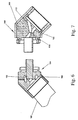
- the motor adapter 27 serves as a manifold to direct the air into and out of the motor.
- the motor adapter 27 includes an inlet port 100 and discharge grooves 102 that are connected to the hose 107 that, in turn, is connected to the source of high pressure and the discharge receiver.
- the hose 107 for the heretofore known surgical motors is well known, in accordance with embodiments of this invention the hose 107 is modified to reduce the noise level created by the flow of the high pressure air exiting the motor.
- the universal swivel 104 mounted at the end of the hose and fitted into the inlet port of the motor adapter 27 is designed with cross-over holes 108, 110, 112 and 114, that flows the air in a criss-cross pattern to chancel the noise generated by the flowing discharge air.
- a cylindrically shaped flow divider or plug 116 ( Fig.
- the flow passages 118 in the flow divider 116 attenuates the noise that is otherwise created by the high velocity outlet air.
- This surgical motor is particularly efficacious for use in proximity to an MRI motor as noted above, but it also can be used in an environment that doesn't include the MRI machine. However, since this motor includes features that increase power, reduce wear, suppress noise and has an increased life, the concepts included in this motor has utility with other surgical instruments and can also be modified with different materials to reduce the cost of the motor. Additionally, this motor operates almost lubrication free. While the bearing housings include sealed grease compartments, unlike the heretofore motors that operate with an air/oil mist in the motor operating fluid, this motor does not require this condition. Hence, during normal operations, the compressed air driving the vane motor is oil free.
- the motor is pre-treated by an air/oil mist that flows into the motor before being used by the surgeon.
- the normal sequence of operation Is that after the motor has been used in a surgical procedure, the motor is thoroughly cleansed, the motor is connected on line where an air/oil mist is flown therein until the operator feels that the motor has reached its operating speed. The air/mist is then shut down and the motor is sterilized by any well known means such as by autoclave.
Landscapes
- Health & Medical Sciences (AREA)
- Engineering & Computer Science (AREA)
- Surgery (AREA)
- Life Sciences & Earth Sciences (AREA)
- General Health & Medical Sciences (AREA)
- Molecular Biology (AREA)
- Orthopedic Medicine & Surgery (AREA)
- Nuclear Medicine, Radiotherapy & Molecular Imaging (AREA)
- Veterinary Medicine (AREA)
- General Engineering & Computer Science (AREA)
- Biomedical Technology (AREA)
- Heart & Thoracic Surgery (AREA)
- Medical Informatics (AREA)
- Public Health (AREA)
- Animal Behavior & Ethology (AREA)
- Mechanical Engineering (AREA)
- Oral & Maxillofacial Surgery (AREA)
- Dentistry (AREA)
- Dental Tools And Instruments Or Auxiliary Dental Instruments (AREA)
- Surgical Instruments (AREA)
- Magnetic Resonance Imaging Apparatus (AREA)
- Connection Of Motors, Electrical Generators, Mechanical Devices, And The Like (AREA)
Claims (6)
- Pneumatischer chirurgischer Motor (50), der in Gegenwart eines KST-Geräts einsetzbar ist, wobei der chirurgische Motor ein Gehäuse (30) mit einem hinteren und einem vorderen Ende aufweist und aus einem nicht magnetischem Edelstahlmaterial besteht und einen Durchmesser aufweist, der klein genug ist, um einen zylindrischen Handgriff zur Betätigung des Motors durch den Chirurgen aufzunehmen, wobei der Motor (50) - ein Lamellenmotor (53) - eine Spindel (1) aus einem nicht magnetischen Edelstahlmaterial aufweist und im Gehäuse (30) auf drehbare Weise unterstützt wird, wobei die Spindel (1) durch Lager (5) und einen am Gehäuse (30) befestigten Befestigungsmechanismus (52) zur Aufnahme vom Lamellenmotor (53) angetriebener chirurgischer Werkzeuge unterstützt wird, wobei im Gehäuse (30) Kanäle (58, 62) zur Leitung von Pressluft ins Gehäuse (30) und den Lamellenmotor (53) zur Rotation der Spindel (1) angeordnet sind, und wobei im Lamellenmotor (53) eine Ablaßöffnung (55) zum Ablassen gebrauchter Luft aus dem Gehäuse (30) angeordnet ist,
dadurch gekennzeichnet, dass:ein Teil der Pressluft über die Lager (5) zur Kühlung der Lager strömt (5) und die Richtung wechselt, bevor sie in den Lamellenmotor (53) aufgenommen und aus der Ablaßöffnung (55) abgelassen wird. - Pneumatischer chirurgischer Motor (50) nach Anspruch 1, wobei das Gehäuse (30) einen Durchmesser aufweist, der klein genug ist, damit es dem Chirurgen als Handgriff dienen kann, und eine zentral zum Gehäuse (30) angeordnete Einlaßöffnung (59) zur Aufnahme der Pressluft am hinteren Ende des Gehäuses (30) aufweist und Ablaßmittel (55) aufweist, die die gebrauchte Luft in die Peripherie des Gehäuses und am peripheren Ende davon nach außen leitet.
- Pneumatischer chirurgischer Motor (50) nach Anspruch 2, wobei eine mit dem Gehäuse (30) im Wesentlichen deckungsgleiche und an dieses grezende Hülse (40) das Gehäuse (30) umgibt und einen Handgriff für den Bediener definiert, wobei das Gehäuse eine Mehrzahl am Außenumfang davon ausgebildeter, sich axial erstreckender Kerbverzahnungen aufweist, wobei der Apex der Kerbverzahnungen in die Innenfläche der Hülse (40) eingreift und die Vertiefung einen Luftspalt definiert, der als Isolator der Hülse (40) fungiert.
- Pneumatischer chirurgischer Motor (50) mit einem Gehäuse (30) mit einem hinteren und einem vorderen Ende, wobei eine mit dem Gehäuse im Wesentlichen deckungsgleiche und an dieses grenzende Hülse (40) aus Kunststoff das Gehäuse (30) umgibt und einen Durchmesser aufweist, der klein genug ist, um dem Chirurgen als Handgriff zu dienen, wobei das Gehäuse (30) eine Mehrzahl am Außenumfang davon ausgebildeter, sich axial erstreckender Kerbverzahnungen aufweist, die einen Handgriff für den Bediener definieren, wobei der Apex der Kerbverzahnungen in die Innenfläche des Gehäuses (30) eingreift und die Vertiefung einen Luftspalt definiert, der als Isolator der Hülse (40) fungiert, und einen Durchmesser aufweist, der klein genug ist, um einen zylindrischen Handgriff zum Greifen des Motors (50) durch den Chirurgen aufzunehmen, wobei der Motor (50) - ein Lamellenmotor (53) - eine Spindel (1) aus einem nicht magnetischen Edelstahlmaterial aufweist und im Gehäuse (30) auf drehbare Weise unterstützt wird, wobei die Spindel (1) durch Lager (5) und einen am Gehäuse (30) befestigten Befestigungsmechanismus (52) zur Aufnahme vom Lamellenmotor (53) angetriebener chirurgischer Werkzeuge unterstützt wird, wobei im Gehäuse (30) Kanäle (58, 62) zur Leitung von Pressluft ins Gehäuse (30) und den Lamellenmotor (53) zur Rotation der Spindel (1) angeordnet sind, und wobei im Lamellenmotor (53) eine Ablaßöffnung (55) zum Ablassen gebrauchter Luft aus dem Gehäuse (30) angeordnet ist,
dadurch gekennzeichnet, dass:ein Teil der Pressluft über die Lager zur Kühlung der Lager (5) strömt und die Richtung wechselt, bevor sie in den Lamellenmotor (53) aufgenommen und aus der Ablaßöffnung (55) abgelassen wird. - Pneumatischer chirurgischer Motor (5) nach Anspruch 1, 2, 3 oder 4, wobei die Spindel (1) durch Nadellager (8, 9) abgestützt wird, wobei die Nadellager eine Mehrzahl umlaufend montierter Nadeln aufweist, wobei alternierende Nadeln (8) aus einem nicht magnetischen Edelstahlmaterial bestehen und alternierende Nadeln (9) aus Kunststoff bestehen.
- Pneumatischer chirurgischer Motor nach einem der vorstehenden Ansprüche (107), der einen an den chirurgischen Motor (50) angeschlossenen Schlauch zur Leitung von Pressluft in Kanäle (58, 62) im Gehäuse (30) und in den Lamellenmotor (53) zur Rotation der Spindel (1) und einen im Schlauch (107) montierten Stromteiler (116) und Übergangskanäle zur Leitung der Pressluft in einem Gittermuster zur Rauschminderung aufweist.
Priority Applications (1)
| Application Number | Priority Date | Filing Date | Title |
|---|---|---|---|
| EP16150960.9A EP3075951B1 (de) | 2004-04-30 | 2005-03-09 | Chirurgischer pneumatischer motor |
Applications Claiming Priority (2)
| Application Number | Priority Date | Filing Date | Title |
|---|---|---|---|
| US56718904P | 2004-04-30 | 2004-04-30 | |
| PCT/US2005/007659 WO2005110251A2 (en) | 2004-04-30 | 2005-03-09 | Surgical pneumatic motor for use with mri |
Related Child Applications (2)
| Application Number | Title | Priority Date | Filing Date |
|---|---|---|---|
| EP16150960.9A Division EP3075951B1 (de) | 2004-04-30 | 2005-03-09 | Chirurgischer pneumatischer motor |
| EP16150960.9A Division-Into EP3075951B1 (de) | 2004-04-30 | 2005-03-09 | Chirurgischer pneumatischer motor |
Publications (3)
| Publication Number | Publication Date |
|---|---|
| EP1746944A2 EP1746944A2 (de) | 2007-01-31 |
| EP1746944A4 EP1746944A4 (de) | 2010-12-22 |
| EP1746944B1 true EP1746944B1 (de) | 2016-03-02 |
Family
ID=35394636
Family Applications (2)
| Application Number | Title | Priority Date | Filing Date |
|---|---|---|---|
| EP05725045.8A Expired - Lifetime EP1746944B1 (de) | 2004-04-30 | 2005-03-09 | Chirurgischer pneumatischer motor zur verwendung mit mrt |
| EP16150960.9A Expired - Lifetime EP3075951B1 (de) | 2004-04-30 | 2005-03-09 | Chirurgischer pneumatischer motor |
Family Applications After (1)
| Application Number | Title | Priority Date | Filing Date |
|---|---|---|---|
| EP16150960.9A Expired - Lifetime EP3075951B1 (de) | 2004-04-30 | 2005-03-09 | Chirurgischer pneumatischer motor |
Country Status (6)
| Country | Link |
|---|---|
| US (1) | US7527486B2 (de) |
| EP (2) | EP1746944B1 (de) |
| JP (1) | JP5059603B2 (de) |
| CN (1) | CN100575668C (de) |
| AU (1) | AU2005244245B2 (de) |
| WO (1) | WO2005110251A2 (de) |
Families Citing this family (13)
| Publication number | Priority date | Publication date | Assignee | Title |
|---|---|---|---|---|
| US20080177268A1 (en) * | 2002-02-14 | 2008-07-24 | Wolfgang Daum | Minimally-Invasive Approach to Bone-Obstructed Soft Tissue |
| US20070166182A1 (en) * | 2006-01-19 | 2007-07-19 | Mighty Seven International Co., Ltd. | Pneumatic tool |
| US7984838B2 (en) * | 2006-05-04 | 2011-07-26 | Medtronic Ps Medical, Inc. | Recycled helium gas surgical instrument |
| WO2008049109A2 (en) * | 2006-10-19 | 2008-04-24 | The Ohio State University | System and method for cardiovascular exercise stress mri |
| DE102007027170A1 (de) * | 2007-06-13 | 2008-12-18 | Siemens Ag | Magnet-Resonanz-Gerät und Verfahren zur Durchführung einer Magnet-Resonanz-Untersuchung |
| GB0723914D0 (en) | 2007-12-07 | 2008-01-23 | Johnson Electric Sa | A power tool |
| JP4964254B2 (ja) * | 2009-01-08 | 2012-06-27 | 日東工器株式会社 | ベーン式エアモータ |
| AT507563B1 (de) * | 2009-05-15 | 2010-06-15 | Klaffenboeck Johann Mag | Vorrichtung zur betätigung eines endeffektors |
| WO2013020877A1 (de) * | 2011-08-05 | 2013-02-14 | Charité - Universitätsmedizin Berlin | Medizinische vorrichtung |
| WO2013120030A1 (en) | 2012-02-08 | 2013-08-15 | Shining Golden Yida Welding & Cutting Machinery Manufacture Ltd. | Rotary vane air motor with improved vanes and other improvements |
| CN107184228B (zh) * | 2017-07-04 | 2023-03-24 | 宁德职业技术学院 | 一种儿童x光拍摄身体限定装置 |
| CN115573905B (zh) * | 2022-09-20 | 2026-02-17 | 江苏梅花机械有限公司 | 一种真空泵及其控制方法、以及农业机械用制动装置 |
| US12318891B1 (en) * | 2024-03-06 | 2025-06-03 | Kuani Gear Co., Ltd | Pneumatic tool |
Family Cites Families (13)
| Publication number | Priority date | Publication date | Assignee | Title |
|---|---|---|---|---|
| US3429230A (en) * | 1966-11-28 | 1969-02-25 | Robert C Quackenbush | Fluid driven motor |
| US3734652A (en) * | 1970-10-26 | 1973-05-22 | Stryker Corp | Pneumatically powered device |
| JPS5121088B2 (de) * | 1972-02-19 | 1976-06-30 | ||
| US3827384A (en) * | 1972-04-21 | 1974-08-06 | T Lunde | Containership |
| JPS5560446A (en) * | 1978-10-31 | 1980-05-07 | Ushio Kogyo Co | Lowwspeed air motor straight hand piece for dental treatment |
| JPH0244075Y2 (de) * | 1986-11-21 | 1990-11-22 | ||
| JP2723211B2 (ja) * | 1994-08-09 | 1998-03-09 | ユーエイチティー株式会社 | エアーモータ |
| US6033408A (en) * | 1996-07-30 | 2000-03-07 | Midas Rex, L.P. | Resecting tool for magnetic field environment |
| US5730732A (en) * | 1996-12-04 | 1998-03-24 | Ethicon, Inc. | Non-magnetic stainless steel surgical needle |
| US5954141A (en) * | 1997-09-22 | 1999-09-21 | Li; Fen-Lien | Air driven motor for a tool |
| US6589033B1 (en) * | 2000-09-29 | 2003-07-08 | Phoenix Analysis And Design Technologies, Inc. | Unitary sliding vane compressor-expander and electrical generation system |
| US20020165549A1 (en) | 2001-04-30 | 2002-11-07 | Medtronic, Inc. | Surgical instrument and attachment |
| US7614793B2 (en) | 2002-11-27 | 2009-11-10 | The Anspach Effort, Inc | Needle/roller bearing |
-
2005
- 2005-03-08 US US11/074,821 patent/US7527486B2/en not_active Expired - Lifetime
- 2005-03-09 JP JP2007510726A patent/JP5059603B2/ja not_active Expired - Lifetime
- 2005-03-09 CN CN200580013550A patent/CN100575668C/zh not_active Expired - Lifetime
- 2005-03-09 EP EP05725045.8A patent/EP1746944B1/de not_active Expired - Lifetime
- 2005-03-09 WO PCT/US2005/007659 patent/WO2005110251A2/en not_active Ceased
- 2005-03-09 AU AU2005244245A patent/AU2005244245B2/en not_active Expired
- 2005-03-09 EP EP16150960.9A patent/EP3075951B1/de not_active Expired - Lifetime
Also Published As
| Publication number | Publication date |
|---|---|
| EP1746944A4 (de) | 2010-12-22 |
| EP3075951B1 (de) | 2018-12-19 |
| JP5059603B2 (ja) | 2012-10-24 |
| EP3075951A1 (de) | 2016-10-05 |
| AU2005244245A1 (en) | 2005-11-24 |
| EP1746944A2 (de) | 2007-01-31 |
| CN100575668C (zh) | 2009-12-30 |
| WO2005110251A2 (en) | 2005-11-24 |
| JP2007535976A (ja) | 2007-12-13 |
| US7527486B2 (en) | 2009-05-05 |
| CN101103177A (zh) | 2008-01-09 |
| WO2005110251A3 (en) | 2007-08-09 |
| AU2005244245B2 (en) | 2012-03-29 |
| US20050245913A1 (en) | 2005-11-03 |
Similar Documents
| Publication | Publication Date | Title |
|---|---|---|
| AU2005244248B2 (en) | Surgical pneumatic motor | |
| EP1746944B1 (de) | Chirurgischer pneumatischer motor zur verwendung mit mrt | |
| US6270345B1 (en) | Vane motor for dental and medical handpieces | |
| TWI751555B (zh) | 用於切割工具的渦輪驅動動力單元 | |
| CN102971535A (zh) | 涡旋流体机械 | |
| JP2016215329A (ja) | 流体を流動させるための貫通孔が形成された主軸構造、電動機、および工作機械 | |
| CN101686835A (zh) | 用于动力外科器械的马达组件 | |
| CN114704483A (zh) | 一种空气循环机 | |
| US7261526B1 (en) | Cylinder for a vane motor | |
| JP2019157729A (ja) | 両回転スクロール型圧縮機 | |
| US10746192B2 (en) | Rotary machine and impeller | |
| EP4264017A1 (de) | Turbinenmotorspindelanordnung für live-werkzeugmaschinen und multitasking-maschinen | |
| CN221129928U (zh) | 一种高效散热的动力手柄 | |
| JPH08276339A (ja) | 増速スピンドル装置 | |
| TWI849954B (zh) | 液壓旋轉裝置 | |
| CN222643257U (zh) | 超声主轴 | |
| CN119606480B (zh) | 一种手术磨钻 | |
| US20250073787A1 (en) | Pneumatic vibration device with rotatable piston shaft | |
| EP3758622B1 (de) | Ölfreier pneumatikmotor | |
| CN119825847A (zh) | 割灌机连接盘组合 | |
| JP2026510231A (ja) | シャフト構成要素、駆動アセンブリ、および車両 | |
| CN108495735B (zh) | 气动工具 | |
| JPH11107954A (ja) | ベーンコンプレッサ | |
| JPH0533245Y2 (de) | ||
| KR19980063966U (ko) | 공압모터 |
Legal Events
| Date | Code | Title | Description |
|---|---|---|---|
| PUAI | Public reference made under article 153(3) epc to a published international application that has entered the european phase |
Free format text: ORIGINAL CODE: 0009012 |
|
| 17P | Request for examination filed |
Effective date: 20061123 |
|
| AK | Designated contracting states |
Kind code of ref document: A2 Designated state(s): AT BE BG CH CY CZ DE DK EE ES FI FR GB GR HU IE IS IT LI LT LU MC NL PL PT RO SE SI SK TR |
|
| AX | Request for extension of the european patent |
Extension state: AL BA HR LV MK YU |
|
| DAX | Request for extension of the european patent (deleted) | ||
| PUAK | Availability of information related to the publication of the international search report |
Free format text: ORIGINAL CODE: 0009015 |
|
| RIC1 | Information provided on ipc code assigned before grant |
Ipc: F04C 18/00 20060101ALI20070917BHEP Ipc: F03C 2/00 20060101AFI20070917BHEP Ipc: F04C 2/00 20060101ALI20070917BHEP Ipc: F03C 4/00 20060101ALI20070917BHEP |
|
| A4 | Supplementary search report drawn up and despatched |
Effective date: 20101122 |
|
| RIC1 | Information provided on ipc code assigned before grant |
Ipc: F01C 21/06 20060101ALI20101116BHEP Ipc: F01C 1/344 20060101AFI20101116BHEP |
|
| 17Q | First examination report despatched |
Effective date: 20120213 |
|
| GRAP | Despatch of communication of intention to grant a patent |
Free format text: ORIGINAL CODE: EPIDOSNIGR1 |
|
| INTG | Intention to grant announced |
Effective date: 20150401 |
|
| RAP1 | Party data changed (applicant data changed or rights of an application transferred) |
Owner name: DEPUY SYNTHES PRODUCTS, INC. |
|
| GRAS | Grant fee paid |
Free format text: ORIGINAL CODE: EPIDOSNIGR3 |
|
| GRAA | (expected) grant |
Free format text: ORIGINAL CODE: 0009210 |
|
| AK | Designated contracting states |
Kind code of ref document: B1 Designated state(s): AT BE BG CH CY CZ DE DK EE ES FI FR GB GR HU IE IS IT LI LT LU MC NL PL PT RO SE SI SK TR |
|
| REG | Reference to a national code |
Ref country code: GB Ref legal event code: FG4D Ref country code: NL Ref legal event code: FP |
|
| REG | Reference to a national code |
Ref country code: FR Ref legal event code: PLFP Year of fee payment: 12 |
|
| REG | Reference to a national code |
Ref country code: AT Ref legal event code: REF Ref document number: 778202 Country of ref document: AT Kind code of ref document: T Effective date: 20160315 Ref country code: CH Ref legal event code: EP |
|
| REG | Reference to a national code |
Ref country code: IE Ref legal event code: FG4D |
|
| REG | Reference to a national code |
Ref country code: DE Ref legal event code: R096 Ref document number: 602005048541 Country of ref document: DE |
|
| REG | Reference to a national code |
Ref country code: LT Ref legal event code: MG4D |
|
| REG | Reference to a national code |
Ref country code: AT Ref legal event code: MK05 Ref document number: 778202 Country of ref document: AT Kind code of ref document: T Effective date: 20160302 |
|
| PG25 | Lapsed in a contracting state [announced via postgrant information from national office to epo] |
Ref country code: ES Free format text: LAPSE BECAUSE OF FAILURE TO SUBMIT A TRANSLATION OF THE DESCRIPTION OR TO PAY THE FEE WITHIN THE PRESCRIBED TIME-LIMIT Effective date: 20160302 Ref country code: GR Free format text: LAPSE BECAUSE OF FAILURE TO SUBMIT A TRANSLATION OF THE DESCRIPTION OR TO PAY THE FEE WITHIN THE PRESCRIBED TIME-LIMIT Effective date: 20160603 Ref country code: FI Free format text: LAPSE BECAUSE OF FAILURE TO SUBMIT A TRANSLATION OF THE DESCRIPTION OR TO PAY THE FEE WITHIN THE PRESCRIBED TIME-LIMIT Effective date: 20160302 |
|
| PG25 | Lapsed in a contracting state [announced via postgrant information from national office to epo] |
Ref country code: AT Free format text: LAPSE BECAUSE OF FAILURE TO SUBMIT A TRANSLATION OF THE DESCRIPTION OR TO PAY THE FEE WITHIN THE PRESCRIBED TIME-LIMIT Effective date: 20160302 Ref country code: BE Free format text: LAPSE BECAUSE OF NON-PAYMENT OF DUE FEES Effective date: 20160331 Ref country code: PL Free format text: LAPSE BECAUSE OF FAILURE TO SUBMIT A TRANSLATION OF THE DESCRIPTION OR TO PAY THE FEE WITHIN THE PRESCRIBED TIME-LIMIT Effective date: 20160302 Ref country code: SE Free format text: LAPSE BECAUSE OF FAILURE TO SUBMIT A TRANSLATION OF THE DESCRIPTION OR TO PAY THE FEE WITHIN THE PRESCRIBED TIME-LIMIT Effective date: 20160302 Ref country code: LT Free format text: LAPSE BECAUSE OF FAILURE TO SUBMIT A TRANSLATION OF THE DESCRIPTION OR TO PAY THE FEE WITHIN THE PRESCRIBED TIME-LIMIT Effective date: 20160302 |
|
| PG25 | Lapsed in a contracting state [announced via postgrant information from national office to epo] |
Ref country code: IS Free format text: LAPSE BECAUSE OF FAILURE TO SUBMIT A TRANSLATION OF THE DESCRIPTION OR TO PAY THE FEE WITHIN THE PRESCRIBED TIME-LIMIT Effective date: 20160702 Ref country code: EE Free format text: LAPSE BECAUSE OF FAILURE TO SUBMIT A TRANSLATION OF THE DESCRIPTION OR TO PAY THE FEE WITHIN THE PRESCRIBED TIME-LIMIT Effective date: 20160302 |
|
| PG25 | Lapsed in a contracting state [announced via postgrant information from national office to epo] |
Ref country code: CZ Free format text: LAPSE BECAUSE OF FAILURE TO SUBMIT A TRANSLATION OF THE DESCRIPTION OR TO PAY THE FEE WITHIN THE PRESCRIBED TIME-LIMIT Effective date: 20160302 Ref country code: SK Free format text: LAPSE BECAUSE OF FAILURE TO SUBMIT A TRANSLATION OF THE DESCRIPTION OR TO PAY THE FEE WITHIN THE PRESCRIBED TIME-LIMIT Effective date: 20160302 Ref country code: RO Free format text: LAPSE BECAUSE OF FAILURE TO SUBMIT A TRANSLATION OF THE DESCRIPTION OR TO PAY THE FEE WITHIN THE PRESCRIBED TIME-LIMIT Effective date: 20160302 Ref country code: PT Free format text: LAPSE BECAUSE OF FAILURE TO SUBMIT A TRANSLATION OF THE DESCRIPTION OR TO PAY THE FEE WITHIN THE PRESCRIBED TIME-LIMIT Effective date: 20160704 |
|
| REG | Reference to a national code |
Ref country code: DE Ref legal event code: R097 Ref document number: 602005048541 Country of ref document: DE |
|
| REG | Reference to a national code |
Ref country code: IE Ref legal event code: MM4A |
|
| PG25 | Lapsed in a contracting state [announced via postgrant information from national office to epo] |
Ref country code: BE Free format text: LAPSE BECAUSE OF FAILURE TO SUBMIT A TRANSLATION OF THE DESCRIPTION OR TO PAY THE FEE WITHIN THE PRESCRIBED TIME-LIMIT Effective date: 20160302 |
|
| PLBE | No opposition filed within time limit |
Free format text: ORIGINAL CODE: 0009261 |
|
| STAA | Information on the status of an ep patent application or granted ep patent |
Free format text: STATUS: NO OPPOSITION FILED WITHIN TIME LIMIT |
|
| PG25 | Lapsed in a contracting state [announced via postgrant information from national office to epo] |
Ref country code: DK Free format text: LAPSE BECAUSE OF FAILURE TO SUBMIT A TRANSLATION OF THE DESCRIPTION OR TO PAY THE FEE WITHIN THE PRESCRIBED TIME-LIMIT Effective date: 20160302 Ref country code: IE Free format text: LAPSE BECAUSE OF NON-PAYMENT OF DUE FEES Effective date: 20160309 |
|
| 26N | No opposition filed |
Effective date: 20161205 |
|
| REG | Reference to a national code |
Ref country code: FR Ref legal event code: PLFP Year of fee payment: 13 |
|
| PG25 | Lapsed in a contracting state [announced via postgrant information from national office to epo] |
Ref country code: SI Free format text: LAPSE BECAUSE OF FAILURE TO SUBMIT A TRANSLATION OF THE DESCRIPTION OR TO PAY THE FEE WITHIN THE PRESCRIBED TIME-LIMIT Effective date: 20160302 Ref country code: BG Free format text: LAPSE BECAUSE OF FAILURE TO SUBMIT A TRANSLATION OF THE DESCRIPTION OR TO PAY THE FEE WITHIN THE PRESCRIBED TIME-LIMIT Effective date: 20160602 |
|
| REG | Reference to a national code |
Ref country code: FR Ref legal event code: PLFP Year of fee payment: 14 |
|
| PG25 | Lapsed in a contracting state [announced via postgrant information from national office to epo] |
Ref country code: CY Free format text: LAPSE BECAUSE OF FAILURE TO SUBMIT A TRANSLATION OF THE DESCRIPTION OR TO PAY THE FEE WITHIN THE PRESCRIBED TIME-LIMIT Effective date: 20160302 Ref country code: HU Free format text: LAPSE BECAUSE OF FAILURE TO SUBMIT A TRANSLATION OF THE DESCRIPTION OR TO PAY THE FEE WITHIN THE PRESCRIBED TIME-LIMIT; INVALID AB INITIO Effective date: 20050309 |
|
| PG25 | Lapsed in a contracting state [announced via postgrant information from national office to epo] |
Ref country code: TR Free format text: LAPSE BECAUSE OF FAILURE TO SUBMIT A TRANSLATION OF THE DESCRIPTION OR TO PAY THE FEE WITHIN THE PRESCRIBED TIME-LIMIT Effective date: 20160302 Ref country code: LU Free format text: LAPSE BECAUSE OF NON-PAYMENT OF DUE FEES Effective date: 20160309 Ref country code: MC Free format text: LAPSE BECAUSE OF FAILURE TO SUBMIT A TRANSLATION OF THE DESCRIPTION OR TO PAY THE FEE WITHIN THE PRESCRIBED TIME-LIMIT Effective date: 20160302 |
|
| REG | Reference to a national code |
Ref country code: DE Ref legal event code: R082 Ref document number: 602005048541 Country of ref document: DE |
|
| PGFP | Annual fee paid to national office [announced via postgrant information from national office to epo] |
Ref country code: NL Payment date: 20240215 Year of fee payment: 20 |
|
| PGFP | Annual fee paid to national office [announced via postgrant information from national office to epo] |
Ref country code: DE Payment date: 20240130 Year of fee payment: 20 Ref country code: GB Payment date: 20240201 Year of fee payment: 20 |
|
| PGFP | Annual fee paid to national office [announced via postgrant information from national office to epo] |
Ref country code: IT Payment date: 20240212 Year of fee payment: 20 Ref country code: FR Payment date: 20240213 Year of fee payment: 20 |
|
| PGFP | Annual fee paid to national office [announced via postgrant information from national office to epo] |
Ref country code: CH Payment date: 20240401 Year of fee payment: 20 |
|
| REG | Reference to a national code |
Ref country code: DE Ref legal event code: R071 Ref document number: 602005048541 Country of ref document: DE |
|
| REG | Reference to a national code |
Ref country code: NL Ref legal event code: MK Effective date: 20250308 |
|
| REG | Reference to a national code |
Ref country code: CH Ref legal event code: PL |
|
| REG | Reference to a national code |
Ref country code: GB Ref legal event code: PE20 Expiry date: 20250308 |
|
| PG25 | Lapsed in a contracting state [announced via postgrant information from national office to epo] |
Ref country code: GB Free format text: LAPSE BECAUSE OF EXPIRATION OF PROTECTION Effective date: 20250308 |