EP3758622B1 - Ölfreier pneumatikmotor - Google Patents
Ölfreier pneumatikmotor Download PDFInfo
- Publication number
- EP3758622B1 EP3758622B1 EP19713241.8A EP19713241A EP3758622B1 EP 3758622 B1 EP3758622 B1 EP 3758622B1 EP 19713241 A EP19713241 A EP 19713241A EP 3758622 B1 EP3758622 B1 EP 3758622B1
- Authority
- EP
- European Patent Office
- Prior art keywords
- vanes
- driven shaft
- pneumatic drill
- drill according
- vane
- Prior art date
- Legal status (The legal status is an assumption and is not a legal conclusion. Google has not performed a legal analysis and makes no representation as to the accuracy of the status listed.)
- Active
Links
Images




Classifications
-
- B—PERFORMING OPERATIONS; TRANSPORTING
- B23—MACHINE TOOLS; METAL-WORKING NOT OTHERWISE PROVIDED FOR
- B23B—TURNING; BORING
- B23B45/00—Hand-held or like portable drilling machines, e.g. drill guns; Equipment therefor
- B23B45/04—Hand-held or like portable drilling machines, e.g. drill guns; Equipment therefor driven by fluid-pressure or pneumatic power
- B23B45/044—Rotary vane type motors
-
- A—HUMAN NECESSITIES
- A61—MEDICAL OR VETERINARY SCIENCE; HYGIENE
- A61B—DIAGNOSIS; SURGERY; IDENTIFICATION
- A61B17/00—Surgical instruments, devices or methods
- A61B17/16—Instruments for performing osteoclasis; Drills or chisels for bones; Trepans
- A61B17/1613—Component parts
- A61B17/1628—Motors; Power supplies
-
- A—HUMAN NECESSITIES
- A61—MEDICAL OR VETERINARY SCIENCE; HYGIENE
- A61B—DIAGNOSIS; SURGERY; IDENTIFICATION
- A61B17/00—Surgical instruments, devices or methods
- A61B17/16—Instruments for performing osteoclasis; Drills or chisels for bones; Trepans
- A61B17/1613—Component parts
- A61B17/1622—Drill handpieces
- A61B17/1624—Drive mechanisms therefor
-
- F—MECHANICAL ENGINEERING; LIGHTING; HEATING; WEAPONS; BLASTING
- F01—MACHINES OR ENGINES IN GENERAL; ENGINE PLANTS IN GENERAL; STEAM ENGINES
- F01C—ROTARY-PISTON OR OSCILLATING-PISTON MACHINES OR ENGINES
- F01C1/00—Rotary-piston machines or engines
- F01C1/30—Rotary-piston machines or engines having the characteristics covered by two or more groups F01C1/02, F01C1/08, F01C1/22, F01C1/24 or having the characteristics covered by one of these groups together with some other type of movement between co-operating members
- F01C1/34—Rotary-piston machines or engines having the characteristics covered by two or more groups F01C1/02, F01C1/08, F01C1/22, F01C1/24 or having the characteristics covered by one of these groups together with some other type of movement between co-operating members having the movement defined in group F01C1/08 or F01C1/22 and relative reciprocation between the co-operating members
- F01C1/344—Rotary-piston machines or engines having the characteristics covered by two or more groups F01C1/02, F01C1/08, F01C1/22, F01C1/24 or having the characteristics covered by one of these groups together with some other type of movement between co-operating members having the movement defined in group F01C1/08 or F01C1/22 and relative reciprocation between the co-operating members with vanes reciprocating with respect to the inner member
- F01C1/3441—Rotary-piston machines or engines having the characteristics covered by two or more groups F01C1/02, F01C1/08, F01C1/22, F01C1/24 or having the characteristics covered by one of these groups together with some other type of movement between co-operating members having the movement defined in group F01C1/08 or F01C1/22 and relative reciprocation between the co-operating members with vanes reciprocating with respect to the inner member the inner and outer member being in contact along one line or continuous surface substantially parallel to the axis of rotation
-
- A—HUMAN NECESSITIES
- A61—MEDICAL OR VETERINARY SCIENCE; HYGIENE
- A61B—DIAGNOSIS; SURGERY; IDENTIFICATION
- A61B17/00—Surgical instruments, devices or methods
- A61B2017/00367—Details of actuation of instruments, e.g. relations between pushing buttons, or the like, and activation of the tool, working tip, or the like
- A61B2017/00398—Details of actuation of instruments, e.g. relations between pushing buttons, or the like, and activation of the tool, working tip, or the like using powered actuators, e.g. stepper motors, solenoids
-
- A—HUMAN NECESSITIES
- A61—MEDICAL OR VETERINARY SCIENCE; HYGIENE
- A61B—DIAGNOSIS; SURGERY; IDENTIFICATION
- A61B17/00—Surgical instruments, devices or methods
- A61B2017/00535—Surgical instruments, devices or methods pneumatically or hydraulically operated
- A61B2017/00544—Surgical instruments, devices or methods pneumatically or hydraulically operated pneumatically
-
- A—HUMAN NECESSITIES
- A61—MEDICAL OR VETERINARY SCIENCE; HYGIENE
- A61B—DIAGNOSIS; SURGERY; IDENTIFICATION
- A61B17/00—Surgical instruments, devices or methods
- A61B2017/00831—Material properties
- A61B2017/0084—Material properties low friction
- A61B2017/00845—Material properties low friction of moving parts with respect to each other
-
- A—HUMAN NECESSITIES
- A61—MEDICAL OR VETERINARY SCIENCE; HYGIENE
- A61B—DIAGNOSIS; SURGERY; IDENTIFICATION
- A61B17/00—Surgical instruments, devices or methods
- A61B17/16—Instruments for performing osteoclasis; Drills or chisels for bones; Trepans
- A61B17/1644—Instruments for performing osteoclasis; Drills or chisels for bones; Trepans using fluid other than turbine drive fluid
- A61B2017/1653—Instruments for performing osteoclasis; Drills or chisels for bones; Trepans using fluid other than turbine drive fluid for lubrication
-
- B—PERFORMING OPERATIONS; TRANSPORTING
- B23—MACHINE TOOLS; METAL-WORKING NOT OTHERWISE PROVIDED FOR
- B23B—TURNING; BORING
- B23B2270/00—Details of turning, boring or drilling machines, processes or tools not otherwise provided for
- B23B2270/02—Use of a particular power source
- B23B2270/027—Pneumatics
-
- F—MECHANICAL ENGINEERING; LIGHTING; HEATING; WEAPONS; BLASTING
- F01—MACHINES OR ENGINES IN GENERAL; ENGINE PLANTS IN GENERAL; STEAM ENGINES
- F01C—ROTARY-PISTON OR OSCILLATING-PISTON MACHINES OR ENGINES
- F01C13/00—Adaptations of machines or engines for special use; Combinations of engines with devices driven thereby
- F01C13/02—Adaptations of machines or engines for special use; Combinations of engines with devices driven thereby for driving hand-held tools or the like
Definitions
- the present disclosure relates to a pneumatic drill and more particularly to an oil-less pneumatic motor for a drill having graphite vane members.
- US5782836 discloses a pneumatic drill according to the preamble of independent claims 1 and 8.
- Figure 1 discloses a pneumatic drill 10 which has a pneumatic motor 12, tool engaging chuck 14, and a member or hose 16 carrying a high pressure air supply 18 and air exhaust 20.
- the tool engaging chuck 14 is configured to couple to a rotating tool such as a drill bit or cutting rasp.
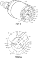
- FIGS 2, 3A and 3B represent a sectional view of the pneumatic motor 12.
- the pneumatic motor 12 has a housing 22 defining the high pressure air input 18 and an air output or exhaust 20, and defines an internal cylindrical chamber 23 having bearing surfaces 24 defining a through bore 25 along the longitudinal axis 27 of the motor.
- the motor 12 has a driven shaft 26 coupled to the tool engaging chuck 14.
- the driven shaft 26, which defines a plurality of longitudinal slots 30, is disposed within the cylindrical chamber 23 and has a longitudinal axis 29 offset from the housing chamber through axis 27.
- a plurality of vanes 28 being at least partially formed of graphite are individually and slidably disposed within one of the plurality of longitudinal slots 30.
- the placement of the offset driven shaft 26 causes one of the vanes 28 to be longer than an adjacent vane 28 or extend radially outwardly from the shaft 26 a greater distance. This allows and provides for a larger area, which interacts with the high pressure gas, leading to the rotation of the driven shaft 26.
- air pressure causes the rotation of the driven shaft 26, thus causing rotation of a tool held by the tool engaging chuck 14. Centrifugal forces from this rotation of the driven shaft 26 pulls all of the vanes 28 in a radial direction and positions a portion of each of the vanes 28 into engagement with the housing inner bearing surface 24, thus forming a bearing surface 37 for the high pressure.
- Each vane 28 has a bearing edge 39 slidably engaged against the bearing surface 24 that has at least partially exposed graphite to reduce the amount of friction between the vane 28 and a housing bearing surface 24.
- the bearing surface 24 is formed by a graphite sleeve 24' inserted in the bore 25, as shown in Figure 4B .
- the graphite sleeve can be .10 to .05 inches (2.54 to 1.27 mm) in thickness.
- the vanes 28 As the vanes 28 engage this bearing surface 24 or 24' and rotate along with the driven shaft 26, the vanes 28 define a plurality of separable chambers that allow for the flow of compressed air from the air supply 18, into the defined chamber 31, and after turning the shaft, out the exhaust port 20 similar to a paddle wheel.
- three vanes 28 are radially disposed within the three equally spaced longitudinal slots 30 defined within the driven shaft 26 and slide within the slots 30 during rotation.
- the driven shaft 26 defines three longitudinal slots 30.
- the first, second, and third vanes 28 have graphite, and are individually disposed within one of the three longitudinal slots 30 .
- the first and second of the vanes, the housing, and the driven shaft define a high pressure compression chamber coupled to the high pressure air source.
- the second and third of the vanes 28, the housing, and the driven shaft 26 define a low pressure compression chamber which is fluidly coupled to the exhaust port 20.
- Figures 4A and 4B represent a housing member that when disposed within and positioned adjacent to a drill housing 36 defines the high pressure input 18 and output air passages 20, and interior cylindrical bearing surfaces 24 which interact with the movable vane members 28.
- a plurality of input ports 18' that are fluidly coupled to the high-pressure air supply.
- a plurality of output ports 20' that allows for the passage of fluid within the chamber out of the pneumatic motor and into the output port 20'.
- the housing 22 can be formed of stainless steel, or polymer.
- the housing 22 bearing surface 24 has a graphite sleeve to reduce the friction between the moving vanes 28 and the bearing surface 24, such as the graphite sleeve 24', shown in Figure 4B .
- the housing 22 also defines a pair of inner surfaces 21 that support the bearings 34, that align the driven shaft 26 in a proper orientation within the cylindrical chamber and the input 18' and output 20' ports.
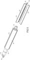
- FIG 5 represents an exploded view of a driven shaft 26 and associated vanes 28 of the motor shown in Figure 2 .
- the driven shaft 26 has at least one flat surface 38 that engages the tool-engaging member or chuck 14. Disposed toward the ends of the driven shaft 26 is a pair of cylindrical surfaces 42 that are conformed to couple to the bearings 34.
- the vanes 28 are slidably disposed within the slots 30 in a manner that allows the relative sliding of the vanes 28 within the slots 30 in a radial direction.
- the driven shaft 26 is rotated, applying centrifugal forces onto the vanes 28, pulling them into engagement with the bearing surface 24 or 24' and exposing side surfaces which increase the effect of the compressed are on the vanes.
- the vanes 28 are displaced by interaction with the bearing surface back into the slot 30.
- FIGS 6A-6D represent graphite containing vanes 28 according to the present teachings.
- These vanes 28 are preferably formed with graphite lubricant material. Because of the sensitivity of graphite to impact induced fracture, the vanes 28 are preferably formed of composite materials that incorporate graphite.
- the vanes can be formed of a polymer such as PEEK with graphite in various forms which each have different properties.
- the vanes 28 have a first edge 44, which interfaces against the cylindrical bearing surface.
- the edge 44 has a surface that has exposed graphite that interfaces with the housing bearing surface.
- the sides 46 of the vanes 28 interface with the metal slots 30 formed within the driven shaft 26.
- the vanes can have a plurality of off standing flanges 47.
- the edges of the vanes 28 can be beveled to reduce the interaction of the vanes 28 with the slots.
- these planar sides 46 preferably have incorporated graphite which assist in the relative movement of the vanes 46 with respect to the rotatable shaft 26.
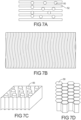
- Figures 7A-7D represent material construction of the vanes shown in Figures 6A-6D .
- the vanes can be formed of graphite containing composites.
- the graphite material can be in the form of a powder 50, incorporated into a polymer matrix 52. This can occur by providing layers of polymer 52 and having graphite powder 50 incorporated there between.
- the polymer can have a specific volume fraction of graphite powder incorporated into a liquid melt polymer.
- the powder can be of a diameter from about 1000 nm to 100,000 nm, and can have a volume fraction from 10% graphite to about 90% graphite.
- the composite material can be formed of alternating layers of graphite and polymer matrix such as PEEK. These layers can be parallel or perpendicular to the longitudinal axis of the shaft 26.
- the laminate can be formed such that the material layers within the vane 28 are visible along the bearing edge 39 of the vane 28, thus exposing the graphite material to the cylindrical bearing surface.
- the graphite can be in tubular or fiber form 56.
- the material can have fibers aligned either in the longitudinal direction of the driven shaft, or perpendicular to the cylindrical bearing wall. As the vane 28 wears, graphite is exposed, thus functioning as a dry lubricant between the moving vane and the bearing surface. Abrasion and wear materials are transferred out of the pneumatic motor through the exhaust port 20.
- the material of the vanes can be a graphite honeycomb 58, having polymer matrix defining the honeycomb structure. Upon wear of the vane, the graphite is exposed, thus reducing friction at the vane to cylinder interface.
- Example embodiments are provided so that this disclosure will be thorough, and will fully convey the scope to those who are skilled in the art. Numerous specific details are set forth such as examples of specific components, devices, and methods, to provide a thorough understanding of embodiments of the present disclosure. It will be apparent to those skilled in the art that specific details need not be employed, that example embodiments may be embodied in many different forms and that neither should be construed to limit the scope of the disclosure. In some example embodiments, well-known processes, well-known device structures, and well-known technologies are not described in detail.
- first, second, third, etc. may be used herein to describe various elements, components, regions, layers and/or sections, these elements, components, regions, layers and/or sections should not be limited by these terms. These terms may be only used to distinguish one element, component, region, layer or section from another region, layer or section. Terms such as “first,” “second,” and other numerical terms when used herein do not imply a sequence or order unless clearly indicated by the context. Thus, a first element, component, region, layer or section discussed below could be termed a second element, component, region, layer or section without departing from the teachings of the example embodiments.
- spatially relative terms such as “inner,” “outer,” “beneath,” “below,” “lower,” “above,” “upper,” and the like, may be used herein for ease of description to describe one element or feature's relationship to another element(s) or feature(s) as illustrated in the figures.
- Spatially relative terms may be intended to encompass different orientations of the device in use or operation in addition to the orientation depicted in the figures. For example, if the device in the figures is turned over, elements described as “below” or “beneath” other elements or features would then be oriented “above” the other elements or features.
- the example term “below” can encompass both an orientation of above and below.
- the device may be otherwise oriented (rotated 90 degrees or at other orientations) and the spatially relative descriptors used herein interpreted accordingly.
Landscapes
- Health & Medical Sciences (AREA)
- Engineering & Computer Science (AREA)
- Surgery (AREA)
- Life Sciences & Earth Sciences (AREA)
- Biomedical Technology (AREA)
- Heart & Thoracic Surgery (AREA)
- Orthopedic Medicine & Surgery (AREA)
- Nuclear Medicine, Radiotherapy & Molecular Imaging (AREA)
- Dentistry (AREA)
- Veterinary Medicine (AREA)
- Public Health (AREA)
- Oral & Maxillofacial Surgery (AREA)
- Medical Informatics (AREA)
- Molecular Biology (AREA)
- Animal Behavior & Ethology (AREA)
- General Health & Medical Sciences (AREA)
- Mechanical Engineering (AREA)
- General Engineering & Computer Science (AREA)
- Surgical Instruments (AREA)
- Sliding-Contact Bearings (AREA)
Claims (13)
- Druckluftbohrer, umfassend:ein Werkzeugeingriffsspannfutter (14);einen Druckluftmotor (12), der aufweist:ein Element, das einen Lufteingang (18) und einen Luftausgang (20) definiert;ein Gehäuse (22), das eine innere zylindrische Kammer definiert, die eine Auflageoberfläche (24) aufweist, die eine Durchgangsachse aufweist;eine angetriebene Welle (26), die mit dem Werkzeugeingriffsspannfutter gekoppelt ist, wobei die angetriebene Welle eine Vielzahl von Längsschlitzen (30) definiert, wobei die angetriebene Welle innerhalb der zylindrischen Kammer angeordnet ist und eine Längsachse aufweist, die von der Durchgangsachse versetzt ist;eine Vielzahl von Schaufeln (28), die innerhalb eines der Vielzahl von Längsschlitzen einzeln angeordnet sind; undwobei zwei der Schaufeln, das Gehäuse und die angetriebene Welle eine Kompressionskammer definieren; und wobei jede Schaufel eine Auflagekante aufweist, die gegen die Auflageoberfläche verschiebbar in Eingriff steht, dadurch gekennzeichnet, dass jede Schaufel Graphit umfasst; und dadurch, dass die Auflageoberfläche Teil einer Graphithülse ist.
- Druckluftbohrer nach Anspruch 1, wobei jede Schaufel innerhalb eines Schlitzes verschiebbar angeordnet ist.
- Druckluftbohrer nach einem der Ansprüche 1 bis 2, wobei jede Schaufel eine Verbundstruktur aufweist.
- Druckluftbohrer nach Anspruch 3, wobei die Verbundstruktur laminar ist.
- Druckluftbohrer nach Anspruch 3, wobei die Verbundstruktur Graphitpartikel umfasst, die in einer PEEK-Matrix angeordnet sind.
- Druckluftbohrer nach einem der Ansprüche 1 bis 5, umfassend drei Schaufeln, die innerhalb von drei Längsschlitzen radial angeordnet sind, die innerhalb der angetriebenen Welle definiert sind.
- Druckluftbohrer nach Anspruch 6, wobei jede der Schaufeln ein Paar Seitenauflageoberflächen aufweist, die Graphit aufweisen, das konfiguriert ist, um eine erste und eine zweite Seite der Schlitze in Eingriff zu nehmen.
- Druckluftbohrer, umfassend:
einen Druckluftmotor (12), der aufweist:ein Gehäuse (22), das eine innere zylindrische Kammer definiert, die eine Auflageoberfläche (24) aufweist, die eine Durchgangsachse aufweist und einen Lufteinlass und einen Luftauslass definiert;eine angetriebene Welle (26), die eine Vielzahl von Längsschlitzen (30) definiert, die um einen Umfang der angetriebenen Welle gleichmäßig beabstandet sind, wobei die angetriebene Welle innerhalb der Kammer angeordnet ist und eine Längsachse aufweist, die von der Durchgangsachse versetzt ist;eine Vielzahl von Schaufeln (28), die innerhalb eines der Vielzahl von Längsschlitzen einzeln angeordnet sind; und wobei zwei der Schaufeln, das Gehäuse und die angetriebene Welle eine komprimierte Gasaufnahmekammer definieren; und wobei jede Schaufel eine Auflagekante aufweist, die gegen die Auflageoberfläche verschiebbar in Eingriff steht, dadurch gekennzeichnet, dass jede Schaufel Graphit umfasst; und dadurch, dass die Auflageoberfläche Teil einer Graphithülse ist. - Druckluftbohrer nach Anspruch 8, wobei jede Schaufel innerhalb eines Schlitzes verschiebbar angeordnet ist.
- Druckluftbohrer nach einem der Ansprüche 8 und 9, wobei jede Schaufel eine von einer laminaren und einer wabenförmigen Verbundstruktur aufweist.
- Druckluftbohrer nach Anspruch 10, wobei die Verbundstruktur Graphitpartikel umfasst, die in einer Peek-Matrix angeordnet sind.
- Druckluftbohrer nach einem der Ansprüche 8 bis 11, umfassend drei Schaufeln, die innerhalb von drei Längsschlitzen radial angeordnet sind, die innerhalb der Welle definiert sind, wobei die drei Schaufeln eine erste, eine zweite und eine dritte Schaufel umfassen, umfassend Graphit, wobei die erste, die zweite und die dritte Schaufel innerhalb eines der drei Längsschlitze einzeln angeordnet sind.
- Druckluftbohrer nach Anspruch 12, wobei die erste und die zweite der Schaufeln, das Gehäuse und die angetriebene Welle eine Hochdruckkompressionskammer definieren und die zweite und die dritte der Schaufeln, das Gehäuse und die angetriebene Welle eine Niederdruckkompressionskammer definieren.
Applications Claiming Priority (2)
| Application Number | Priority Date | Filing Date | Title |
|---|---|---|---|
| US15/907,583 US11072028B2 (en) | 2018-02-28 | 2018-02-28 | Oil-less pneumatic motor having graphite vanes formed with beveled edges, off-standing flanges, and rounded corners |
| PCT/US2019/019821 WO2019168976A1 (en) | 2018-02-28 | 2019-02-27 | Oil-less pneumatic motor |
Publications (2)
| Publication Number | Publication Date |
|---|---|
| EP3758622A1 EP3758622A1 (de) | 2021-01-06 |
| EP3758622B1 true EP3758622B1 (de) | 2024-03-27 |
Family
ID=65904530
Family Applications (1)
| Application Number | Title | Priority Date | Filing Date |
|---|---|---|---|
| EP19713241.8A Active EP3758622B1 (de) | 2018-02-28 | 2019-02-27 | Ölfreier pneumatikmotor |
Country Status (7)
| Country | Link |
|---|---|
| US (1) | US11072028B2 (de) |
| EP (1) | EP3758622B1 (de) |
| KR (1) | KR20200127994A (de) |
| CN (1) | CN111565652B (de) |
| AU (1) | AU2019227735A1 (de) |
| CA (1) | CA3092570A1 (de) |
| WO (1) | WO2019168976A1 (de) |
Family Cites Families (25)
| Publication number | Priority date | Publication date | Assignee | Title |
|---|---|---|---|---|
| US1444269A (en) * | 1920-11-01 | 1923-02-06 | Walter J Piatt | Rotary pump |
| US2833465A (en) * | 1955-08-02 | 1958-05-06 | Bendix Aviat Corp | Multi-vane positive displacement pump |
| GB957593A (en) * | 1962-08-16 | 1964-05-06 | Anthony Frank Murphy | Positive displacement rotary pump |
| US3254606A (en) * | 1963-12-16 | 1966-06-07 | Nils O Rosaen | Constant delivery pump |
| US3734652A (en) * | 1970-10-26 | 1973-05-22 | Stryker Corp | Pneumatically powered device |
| US4521167A (en) * | 1981-06-11 | 1985-06-04 | Cavalleri Robert J | Low frictional loss rotary vane gas compressor having superior lubrication characteristics |
| US4958995A (en) * | 1986-07-22 | 1990-09-25 | Eagle Industry Co., Ltd. | Vane pump with annular recesses to control vane extension |
| US4804317A (en) | 1987-03-13 | 1989-02-14 | Eaton Corporation | Rotary vane pump with floating rotor side plates |
| DE4421758A1 (de) * | 1994-06-22 | 1996-01-04 | Artur Foehl | Antriebsvorrichtung für einen Gurtstraffer |
| US5782836A (en) * | 1996-07-30 | 1998-07-21 | Midas Rex Pneumatic Tools, Inc. | Resecting tool for magnetic field environment |
| US6364646B1 (en) * | 1999-05-27 | 2002-04-02 | Kevin R. Kirtley | Rotary vane pump with continuous carbon fiber reinforced polyetheretherketone (peek) vanes |
| IL133037A0 (en) * | 1999-07-01 | 2001-03-19 | Medivice Systems Ltd | Improved dental drill head |
| US6270345B1 (en) | 1999-10-28 | 2001-08-07 | Dove Systems, Inc. | Vane motor for dental and medical handpieces |
| JP4685094B2 (ja) * | 2004-04-30 | 2011-05-18 | ジ アンスパック エフォート,インコーポレイテッド | 外科用空気圧モータ |
| US20060089623A1 (en) * | 2004-10-21 | 2006-04-27 | Medtronic, Inc. | Surgical instrument with wear-resistant housing and method of operating same |
| US7222680B2 (en) * | 2004-12-01 | 2007-05-29 | Ingersoll-Rand Company | Pneumatic motor improvements and pneumatic tools incorporating same |
| US7705482B2 (en) * | 2006-10-30 | 2010-04-27 | H&S Autoshot Mfg. Co. Ltd. | Tool having integrated electricity generator with external stator |
| US8556922B2 (en) * | 2007-02-28 | 2013-10-15 | Medtronic Ps Medical, Inc. | Motor assembly for a powered surgical instrument |
| GB2486007B (en) * | 2010-12-01 | 2017-05-10 | Itt Mfg Enterprises Inc | Sliding vane pump |
| US9476428B2 (en) * | 2011-06-01 | 2016-10-25 | R & D Dynamics Corporation | Ultra high pressure turbomachine for waste heat recovery |
| JP5643923B2 (ja) * | 2011-12-21 | 2014-12-24 | 株式会社リッチストーン | ロータリカムリング流体機械 |
| JP6083408B2 (ja) * | 2014-03-25 | 2017-02-22 | 株式会社豊田自動織機 | ベーン型圧縮機 |
| CN106687236B (zh) * | 2014-09-19 | 2019-05-14 | Ntn株式会社 | 滑动部件及其制造方法 |
| JP2016173052A (ja) * | 2015-03-17 | 2016-09-29 | 住友化学株式会社 | 回転圧縮機用ベーン |
| WO2017003803A1 (en) * | 2015-06-30 | 2017-01-05 | The Procter & Gamble Company | Articles of reclaimed polyethylene compositions |
-
2018
- 2018-02-28 US US15/907,583 patent/US11072028B2/en active Active
-
2019
- 2019-02-27 EP EP19713241.8A patent/EP3758622B1/de active Active
- 2019-02-27 CA CA3092570A patent/CA3092570A1/en not_active Abandoned
- 2019-02-27 KR KR1020207023461A patent/KR20200127994A/ko not_active Withdrawn
- 2019-02-27 WO PCT/US2019/019821 patent/WO2019168976A1/en not_active Ceased
- 2019-02-27 CN CN201980007836.5A patent/CN111565652B/zh active Active
- 2019-02-27 AU AU2019227735A patent/AU2019227735A1/en not_active Abandoned
Also Published As
| Publication number | Publication date |
|---|---|
| CN111565652B (zh) | 2024-11-19 |
| US20190262909A1 (en) | 2019-08-29 |
| CN111565652A (zh) | 2020-08-21 |
| AU2019227735A1 (en) | 2020-08-06 |
| US11072028B2 (en) | 2021-07-27 |
| KR20200127994A (ko) | 2020-11-11 |
| CA3092570A1 (en) | 2019-09-06 |
| WO2019168976A1 (en) | 2019-09-06 |
| EP3758622A1 (de) | 2021-01-06 |
Similar Documents
| Publication | Publication Date | Title |
|---|---|---|
| AU2005244248B2 (en) | Surgical pneumatic motor | |
| KR101683299B1 (ko) | 선택제어형 씨일을 갖는 로터리 유니언 | |
| EP2129303B1 (de) | Antriebsanordnung für ein chirurgisches instrument | |
| US7644763B2 (en) | Downhole cutting tool and method | |
| EP2839924A1 (de) | Flüssigkeitszugeführte Vakuum Schneider | |
| EP3758622B1 (de) | Ölfreier pneumatikmotor | |
| CN106605094B (zh) | 活塞致动旋转接头 | |
| CN100575668C (zh) | 用于与磁共振成像一起使用的外科手术气动马达 | |
| EP1096149A2 (de) | Verdrängungspumpe mit Axiallageranordnung | |
| CN105026810A (zh) | 流路切换阀 | |
| EP1636495A1 (de) | Flügelzellenpumpe mit integrierter welle, drehkolben und scheibe | |
| KR102629312B1 (ko) | 효율이 개선된 저널 베어링 | |
| US12049827B2 (en) | Vane wearing detection | |
| JP3935569B2 (ja) | スリッタ | |
| AU2008219483B2 (en) | Motor assembly for a powered surgical instrument | |
| SE530827C2 (sv) | Anordning vid bergborrning | |
| Nie et al. | Work principle and characteristic analyses of hydrostatic bearing. | |
| BR102019012539A2 (pt) | dispositivo e método de aplicação de fluído de corte introjetado em rebolos abrasivos | |
| HK1232278B (zh) | 活塞致动旋转接头 |
Legal Events
| Date | Code | Title | Description |
|---|---|---|---|
| STAA | Information on the status of an ep patent application or granted ep patent |
Free format text: STATUS: UNKNOWN |
|
| STAA | Information on the status of an ep patent application or granted ep patent |
Free format text: STATUS: THE INTERNATIONAL PUBLICATION HAS BEEN MADE |
|
| PUAI | Public reference made under article 153(3) epc to a published international application that has entered the european phase |
Free format text: ORIGINAL CODE: 0009012 |
|
| STAA | Information on the status of an ep patent application or granted ep patent |
Free format text: STATUS: REQUEST FOR EXAMINATION WAS MADE |
|
| 17P | Request for examination filed |
Effective date: 20200819 |
|
| AK | Designated contracting states |
Kind code of ref document: A1 Designated state(s): AL AT BE BG CH CY CZ DE DK EE ES FI FR GB GR HR HU IE IS IT LI LT LU LV MC MK MT NL NO PL PT RO RS SE SI SK SM TR |
|
| AX | Request for extension of the european patent |
Extension state: BA ME |
|
| RIN1 | Information on inventor provided before grant (corrected) |
Inventor name: HUQ, MD ZAHEDUL |
|
| DAV | Request for validation of the european patent (deleted) | ||
| DAX | Request for extension of the european patent (deleted) | ||
| GRAP | Despatch of communication of intention to grant a patent |
Free format text: ORIGINAL CODE: EPIDOSNIGR1 |
|
| STAA | Information on the status of an ep patent application or granted ep patent |
Free format text: STATUS: GRANT OF PATENT IS INTENDED |
|
| INTG | Intention to grant announced |
Effective date: 20231109 |
|
| GRAS | Grant fee paid |
Free format text: ORIGINAL CODE: EPIDOSNIGR3 |
|
| GRAA | (expected) grant |
Free format text: ORIGINAL CODE: 0009210 |
|
| STAA | Information on the status of an ep patent application or granted ep patent |
Free format text: STATUS: THE PATENT HAS BEEN GRANTED |
|
| AK | Designated contracting states |
Kind code of ref document: B1 Designated state(s): AL AT BE BG CH CY CZ DE DK EE ES FI FR GB GR HR HU IE IS IT LI LT LU LV MC MK MT NL NO PL PT RO RS SE SI SK SM TR |
|
| REG | Reference to a national code |
Ref country code: GB Ref legal event code: FG4D |
|
| REG | Reference to a national code |
Ref country code: CH Ref legal event code: EP |
|
| REG | Reference to a national code |
Ref country code: DE Ref legal event code: R096 Ref document number: 602019048988 Country of ref document: DE |
|
| REG | Reference to a national code |
Ref country code: IE Ref legal event code: FG4D |
|
| PG25 | Lapsed in a contracting state [announced via postgrant information from national office to epo] |
Ref country code: LT Free format text: LAPSE BECAUSE OF FAILURE TO SUBMIT A TRANSLATION OF THE DESCRIPTION OR TO PAY THE FEE WITHIN THE PRESCRIBED TIME-LIMIT Effective date: 20240327 |
|
| REG | Reference to a national code |
Ref country code: LT Ref legal event code: MG9D |
|
| PG25 | Lapsed in a contracting state [announced via postgrant information from national office to epo] |
Ref country code: GR Free format text: LAPSE BECAUSE OF FAILURE TO SUBMIT A TRANSLATION OF THE DESCRIPTION OR TO PAY THE FEE WITHIN THE PRESCRIBED TIME-LIMIT Effective date: 20240628 |
|
| PG25 | Lapsed in a contracting state [announced via postgrant information from national office to epo] |
Ref country code: RS Free format text: LAPSE BECAUSE OF FAILURE TO SUBMIT A TRANSLATION OF THE DESCRIPTION OR TO PAY THE FEE WITHIN THE PRESCRIBED TIME-LIMIT Effective date: 20240627 Ref country code: HR Free format text: LAPSE BECAUSE OF FAILURE TO SUBMIT A TRANSLATION OF THE DESCRIPTION OR TO PAY THE FEE WITHIN THE PRESCRIBED TIME-LIMIT Effective date: 20240327 |
|
| PG25 | Lapsed in a contracting state [announced via postgrant information from national office to epo] |
Ref country code: RS Free format text: LAPSE BECAUSE OF FAILURE TO SUBMIT A TRANSLATION OF THE DESCRIPTION OR TO PAY THE FEE WITHIN THE PRESCRIBED TIME-LIMIT Effective date: 20240627 Ref country code: NO Free format text: LAPSE BECAUSE OF FAILURE TO SUBMIT A TRANSLATION OF THE DESCRIPTION OR TO PAY THE FEE WITHIN THE PRESCRIBED TIME-LIMIT Effective date: 20240627 Ref country code: LT Free format text: LAPSE BECAUSE OF FAILURE TO SUBMIT A TRANSLATION OF THE DESCRIPTION OR TO PAY THE FEE WITHIN THE PRESCRIBED TIME-LIMIT Effective date: 20240327 Ref country code: HR Free format text: LAPSE BECAUSE OF FAILURE TO SUBMIT A TRANSLATION OF THE DESCRIPTION OR TO PAY THE FEE WITHIN THE PRESCRIBED TIME-LIMIT Effective date: 20240327 Ref country code: GR Free format text: LAPSE BECAUSE OF FAILURE TO SUBMIT A TRANSLATION OF THE DESCRIPTION OR TO PAY THE FEE WITHIN THE PRESCRIBED TIME-LIMIT Effective date: 20240628 Ref country code: FI Free format text: LAPSE BECAUSE OF FAILURE TO SUBMIT A TRANSLATION OF THE DESCRIPTION OR TO PAY THE FEE WITHIN THE PRESCRIBED TIME-LIMIT Effective date: 20240327 Ref country code: BG Free format text: LAPSE BECAUSE OF FAILURE TO SUBMIT A TRANSLATION OF THE DESCRIPTION OR TO PAY THE FEE WITHIN THE PRESCRIBED TIME-LIMIT Effective date: 20240327 |
|
| REG | Reference to a national code |
Ref country code: NL Ref legal event code: MP Effective date: 20240327 |
|
| PG25 | Lapsed in a contracting state [announced via postgrant information from national office to epo] |
Ref country code: SE Free format text: LAPSE BECAUSE OF FAILURE TO SUBMIT A TRANSLATION OF THE DESCRIPTION OR TO PAY THE FEE WITHIN THE PRESCRIBED TIME-LIMIT Effective date: 20240327 Ref country code: LV Free format text: LAPSE BECAUSE OF FAILURE TO SUBMIT A TRANSLATION OF THE DESCRIPTION OR TO PAY THE FEE WITHIN THE PRESCRIBED TIME-LIMIT Effective date: 20240327 |
|
| PG25 | Lapsed in a contracting state [announced via postgrant information from national office to epo] |
Ref country code: NL Free format text: LAPSE BECAUSE OF FAILURE TO SUBMIT A TRANSLATION OF THE DESCRIPTION OR TO PAY THE FEE WITHIN THE PRESCRIBED TIME-LIMIT Effective date: 20240327 |
|
| REG | Reference to a national code |
Ref country code: AT Ref legal event code: MK05 Ref document number: 1669164 Country of ref document: AT Kind code of ref document: T Effective date: 20240327 |
|
| PG25 | Lapsed in a contracting state [announced via postgrant information from national office to epo] |
Ref country code: NL Free format text: LAPSE BECAUSE OF FAILURE TO SUBMIT A TRANSLATION OF THE DESCRIPTION OR TO PAY THE FEE WITHIN THE PRESCRIBED TIME-LIMIT Effective date: 20240327 |
|
| PG25 | Lapsed in a contracting state [announced via postgrant information from national office to epo] |
Ref country code: IS Free format text: LAPSE BECAUSE OF FAILURE TO SUBMIT A TRANSLATION OF THE DESCRIPTION OR TO PAY THE FEE WITHIN THE PRESCRIBED TIME-LIMIT Effective date: 20240727 |
|
| PG25 | Lapsed in a contracting state [announced via postgrant information from national office to epo] |
Ref country code: PT Free format text: LAPSE BECAUSE OF FAILURE TO SUBMIT A TRANSLATION OF THE DESCRIPTION OR TO PAY THE FEE WITHIN THE PRESCRIBED TIME-LIMIT Effective date: 20240729 Ref country code: SM Free format text: LAPSE BECAUSE OF FAILURE TO SUBMIT A TRANSLATION OF THE DESCRIPTION OR TO PAY THE FEE WITHIN THE PRESCRIBED TIME-LIMIT Effective date: 20240327 |
|
| PG25 | Lapsed in a contracting state [announced via postgrant information from national office to epo] |
Ref country code: ES Free format text: LAPSE BECAUSE OF FAILURE TO SUBMIT A TRANSLATION OF THE DESCRIPTION OR TO PAY THE FEE WITHIN THE PRESCRIBED TIME-LIMIT Effective date: 20240327 |
|
| PG25 | Lapsed in a contracting state [announced via postgrant information from national office to epo] |
Ref country code: CZ Free format text: LAPSE BECAUSE OF FAILURE TO SUBMIT A TRANSLATION OF THE DESCRIPTION OR TO PAY THE FEE WITHIN THE PRESCRIBED TIME-LIMIT Effective date: 20240327 Ref country code: EE Free format text: LAPSE BECAUSE OF FAILURE TO SUBMIT A TRANSLATION OF THE DESCRIPTION OR TO PAY THE FEE WITHIN THE PRESCRIBED TIME-LIMIT Effective date: 20240327 |
|
| PG25 | Lapsed in a contracting state [announced via postgrant information from national office to epo] |
Ref country code: AT Free format text: LAPSE BECAUSE OF FAILURE TO SUBMIT A TRANSLATION OF THE DESCRIPTION OR TO PAY THE FEE WITHIN THE PRESCRIBED TIME-LIMIT Effective date: 20240327 |
|
| PG25 | Lapsed in a contracting state [announced via postgrant information from national office to epo] |
Ref country code: PL Free format text: LAPSE BECAUSE OF FAILURE TO SUBMIT A TRANSLATION OF THE DESCRIPTION OR TO PAY THE FEE WITHIN THE PRESCRIBED TIME-LIMIT Effective date: 20240327 |
|
| PG25 | Lapsed in a contracting state [announced via postgrant information from national office to epo] |
Ref country code: SK Free format text: LAPSE BECAUSE OF FAILURE TO SUBMIT A TRANSLATION OF THE DESCRIPTION OR TO PAY THE FEE WITHIN THE PRESCRIBED TIME-LIMIT Effective date: 20240327 |
|
| PG25 | Lapsed in a contracting state [announced via postgrant information from national office to epo] |
Ref country code: SM Free format text: LAPSE BECAUSE OF FAILURE TO SUBMIT A TRANSLATION OF THE DESCRIPTION OR TO PAY THE FEE WITHIN THE PRESCRIBED TIME-LIMIT Effective date: 20240327 Ref country code: SK Free format text: LAPSE BECAUSE OF FAILURE TO SUBMIT A TRANSLATION OF THE DESCRIPTION OR TO PAY THE FEE WITHIN THE PRESCRIBED TIME-LIMIT Effective date: 20240327 Ref country code: RO Free format text: LAPSE BECAUSE OF FAILURE TO SUBMIT A TRANSLATION OF THE DESCRIPTION OR TO PAY THE FEE WITHIN THE PRESCRIBED TIME-LIMIT Effective date: 20240327 Ref country code: PT Free format text: LAPSE BECAUSE OF FAILURE TO SUBMIT A TRANSLATION OF THE DESCRIPTION OR TO PAY THE FEE WITHIN THE PRESCRIBED TIME-LIMIT Effective date: 20240729 Ref country code: PL Free format text: LAPSE BECAUSE OF FAILURE TO SUBMIT A TRANSLATION OF THE DESCRIPTION OR TO PAY THE FEE WITHIN THE PRESCRIBED TIME-LIMIT Effective date: 20240327 Ref country code: IS Free format text: LAPSE BECAUSE OF FAILURE TO SUBMIT A TRANSLATION OF THE DESCRIPTION OR TO PAY THE FEE WITHIN THE PRESCRIBED TIME-LIMIT Effective date: 20240727 Ref country code: ES Free format text: LAPSE BECAUSE OF FAILURE TO SUBMIT A TRANSLATION OF THE DESCRIPTION OR TO PAY THE FEE WITHIN THE PRESCRIBED TIME-LIMIT Effective date: 20240327 Ref country code: EE Free format text: LAPSE BECAUSE OF FAILURE TO SUBMIT A TRANSLATION OF THE DESCRIPTION OR TO PAY THE FEE WITHIN THE PRESCRIBED TIME-LIMIT Effective date: 20240327 Ref country code: CZ Free format text: LAPSE BECAUSE OF FAILURE TO SUBMIT A TRANSLATION OF THE DESCRIPTION OR TO PAY THE FEE WITHIN THE PRESCRIBED TIME-LIMIT Effective date: 20240327 Ref country code: AT Free format text: LAPSE BECAUSE OF FAILURE TO SUBMIT A TRANSLATION OF THE DESCRIPTION OR TO PAY THE FEE WITHIN THE PRESCRIBED TIME-LIMIT Effective date: 20240327 |
|
| PG25 | Lapsed in a contracting state [announced via postgrant information from national office to epo] |
Ref country code: IT Free format text: LAPSE BECAUSE OF FAILURE TO SUBMIT A TRANSLATION OF THE DESCRIPTION OR TO PAY THE FEE WITHIN THE PRESCRIBED TIME-LIMIT Effective date: 20240327 |
|
| PG25 | Lapsed in a contracting state [announced via postgrant information from national office to epo] |
Ref country code: IT Free format text: LAPSE BECAUSE OF FAILURE TO SUBMIT A TRANSLATION OF THE DESCRIPTION OR TO PAY THE FEE WITHIN THE PRESCRIBED TIME-LIMIT Effective date: 20240327 |
|
| REG | Reference to a national code |
Ref country code: DE Ref legal event code: R097 Ref document number: 602019048988 Country of ref document: DE |
|
| PG25 | Lapsed in a contracting state [announced via postgrant information from national office to epo] |
Ref country code: DK Free format text: LAPSE BECAUSE OF FAILURE TO SUBMIT A TRANSLATION OF THE DESCRIPTION OR TO PAY THE FEE WITHIN THE PRESCRIBED TIME-LIMIT Effective date: 20240327 |
|
| PG25 | Lapsed in a contracting state [announced via postgrant information from national office to epo] |
Ref country code: DK Free format text: LAPSE BECAUSE OF FAILURE TO SUBMIT A TRANSLATION OF THE DESCRIPTION OR TO PAY THE FEE WITHIN THE PRESCRIBED TIME-LIMIT Effective date: 20240327 |
|
| PLBE | No opposition filed within time limit |
Free format text: ORIGINAL CODE: 0009261 |
|
| STAA | Information on the status of an ep patent application or granted ep patent |
Free format text: STATUS: NO OPPOSITION FILED WITHIN TIME LIMIT |
|
| 26N | No opposition filed |
Effective date: 20250103 |
|
| PG25 | Lapsed in a contracting state [announced via postgrant information from national office to epo] |
Ref country code: SI Free format text: LAPSE BECAUSE OF FAILURE TO SUBMIT A TRANSLATION OF THE DESCRIPTION OR TO PAY THE FEE WITHIN THE PRESCRIBED TIME-LIMIT Effective date: 20240327 |
|
| PG25 | Lapsed in a contracting state [announced via postgrant information from national office to epo] |
Ref country code: MC Free format text: LAPSE BECAUSE OF FAILURE TO SUBMIT A TRANSLATION OF THE DESCRIPTION OR TO PAY THE FEE WITHIN THE PRESCRIBED TIME-LIMIT Effective date: 20240327 |
|
| REG | Reference to a national code |
Ref country code: CH Ref legal event code: PL |
|
| PG25 | Lapsed in a contracting state [announced via postgrant information from national office to epo] |
Ref country code: LU Free format text: LAPSE BECAUSE OF NON-PAYMENT OF DUE FEES Effective date: 20250227 |
|
| PG25 | Lapsed in a contracting state [announced via postgrant information from national office to epo] |
Ref country code: CH Free format text: LAPSE BECAUSE OF NON-PAYMENT OF DUE FEES Effective date: 20250228 |
|
| GBPC | Gb: european patent ceased through non-payment of renewal fee |
Effective date: 20250227 |
|
| REG | Reference to a national code |
Ref country code: BE Ref legal event code: MM Effective date: 20250228 |
|
| PG25 | Lapsed in a contracting state [announced via postgrant information from national office to epo] |
Ref country code: GB Free format text: LAPSE BECAUSE OF NON-PAYMENT OF DUE FEES Effective date: 20250227 |
|
| PG25 | Lapsed in a contracting state [announced via postgrant information from national office to epo] |
Ref country code: BE Free format text: LAPSE BECAUSE OF NON-PAYMENT OF DUE FEES Effective date: 20250228 |
|
| PG25 | Lapsed in a contracting state [announced via postgrant information from national office to epo] |
Ref country code: IE Free format text: LAPSE BECAUSE OF NON-PAYMENT OF DUE FEES Effective date: 20250227 |
|
| PGFP | Annual fee paid to national office [announced via postgrant information from national office to epo] |
Ref country code: DE Payment date: 20260121 Year of fee payment: 8 |
|
| PGFP | Annual fee paid to national office [announced via postgrant information from national office to epo] |
Ref country code: FR Payment date: 20260121 Year of fee payment: 8 |