EP1746686B1 - Electrical terminal - Google Patents
Electrical terminal Download PDFInfo
- Publication number
- EP1746686B1 EP1746686B1 EP05015903A EP05015903A EP1746686B1 EP 1746686 B1 EP1746686 B1 EP 1746686B1 EP 05015903 A EP05015903 A EP 05015903A EP 05015903 A EP05015903 A EP 05015903A EP 1746686 B1 EP1746686 B1 EP 1746686B1
- Authority
- EP
- European Patent Office
- Prior art keywords
- connector element
- elements
- latch
- accordance
- central opening
- Prior art date
- Legal status (The legal status is an assumption and is not a legal conclusion. Google has not performed a legal analysis and makes no representation as to the accuracy of the status listed.)
- Active
Links
- 210000002105 tongue Anatomy 0.000 claims description 12
- 210000001331 nose Anatomy 0.000 claims 2
- 239000004020 conductor Substances 0.000 abstract description 13
- 238000000034 method Methods 0.000 description 3
- 230000007704 transition Effects 0.000 description 3
- 238000004519 manufacturing process Methods 0.000 description 2
- 238000002788 crimping Methods 0.000 description 1
- 230000002349 favourable effect Effects 0.000 description 1
- 238000009434 installation Methods 0.000 description 1
- 230000003993 interaction Effects 0.000 description 1
- 239000002184 metal Substances 0.000 description 1
Images
Classifications
-
- H—ELECTRICITY
- H01—ELECTRIC ELEMENTS
- H01R—ELECTRICALLY-CONDUCTIVE CONNECTIONS; STRUCTURAL ASSOCIATIONS OF A PLURALITY OF MUTUALLY-INSULATED ELECTRICAL CONNECTING ELEMENTS; COUPLING DEVICES; CURRENT COLLECTORS
- H01R11/00—Individual connecting elements providing two or more spaced connecting locations for conductive members which are, or may be, thereby interconnected, e.g. end pieces for wires or cables supported by the wire or cable and having means for facilitating electrical connection to some other wire, terminal, or conductive member, blocks of binding posts
- H01R11/11—End pieces or tapping pieces for wires, supported by the wire and for facilitating electrical connection to some other wire, terminal or conductive member
- H01R11/12—End pieces terminating in an eye, hook, or fork
-
- H—ELECTRICITY
- H01—ELECTRIC ELEMENTS
- H01R—ELECTRICALLY-CONDUCTIVE CONNECTIONS; STRUCTURAL ASSOCIATIONS OF A PLURALITY OF MUTUALLY-INSULATED ELECTRICAL CONNECTING ELEMENTS; COUPLING DEVICES; CURRENT COLLECTORS
- H01R4/00—Electrically-conductive connections between two or more conductive members in direct contact, i.e. touching one another; Means for effecting or maintaining such contact; Electrically-conductive connections having two or more spaced connecting locations for conductors and using contact members penetrating insulation
- H01R4/58—Electrically-conductive connections between two or more conductive members in direct contact, i.e. touching one another; Means for effecting or maintaining such contact; Electrically-conductive connections having two or more spaced connecting locations for conductors and using contact members penetrating insulation characterised by the form or material of the contacting members
- H01R4/64—Connections between or with conductive parts having primarily a non-electric function, e.g. frame, casing, rail
Definitions
- the present invention relates to an electrical connection element for connecting an electrical conductor to a bolt, in particular a ground bolt.
- connection elements are also referred to as cable lugs.
- connection elements are frequently used in motor vehicles, wherein usually several such connection elements are connected to a common ground bolt.
- Cable lugs are known from the prior art, in which for connecting the electrical conductor to the connection element, a groove-like elongated receiving area with raised wall areas, in which the electrical conductor can be attached by producing a crimp connection.
- a connecting element for connecting the connecting element to the above-mentioned ground bolt is often used in known from the prior art cable lugs an opening with which the cable lug can be plugged onto the ground bolt, said opening is generally arranged centrally in a connection plate, which is located on the long elongated receiving area connects.
- the ground bolt is usually provided with a thread on which a nut can be screwed after one or more lugs have been plugged with their aforementioned opening on the bolt. If several lugs on top of each other are to be plugged onto a same ground bolt, so you assigns them for reasons of space preferably radially offset from each other.
- the assembly of individual lugs with the already crimped on it conductors on the ground bolt but can be troublesome and time-consuming just in a motor vehicle due to the prevailing narrowness.
- connection elements of the type mentioned are already known, which are provided with locking elements, which serve to connect two axially mutually arranged connection elements rotatably with each other.
- connection element according to the preamble of claim 1. From the US-A-5 759 056 is also a connection element is known, which has latching elements which are rotatably locked with corresponding latching elements of a further connection element.
- the cable lug is also rotated when tightening the nut by the resulting friction with respect to the bolt.
- connection element has an anti-twist device which is suitable for interacting with the bolt passing through the central opening.
- the locking elements provided on the outside of the central opening may be designed differently, but all have in common, regardless of the specific embodiment, that when two identical or provided with each corresponding locking elements connecting elements are set axially against each other, the locking elements of the two connection elements lock together. A twisting of the two connection elements against each other is then no longer possible.
- the locking of the connecting elements together can be made before placing them on the ground bolt, so that the subsequent mounting on the bolt can be done in a single step.
- the rotation of one of the locking elements is formed.
- the rotation of the connection element relative to the bolt passing through the central opening is thus prevented by a latching element which simultaneously serves to latch two electrical connection elements together.
- At least one of the latching elements, which can latch with corresponding latching elements on a second connection element thus has a double function.
- no specially designed connection element is necessary which makes the non-rotatable connection with the bolt, but the connection elements can all be of the same design and, depending on their location with respect to any other connection elements, either a rotationally fixed connection with an overlying or underlying other connection element or a rotationally fixed connection with the bolt.
- the latching elements preferably have latching recesses, wherein these latching recesses may comprise latching lugs formed radially outwardly.
- latching recesses may comprise latching lugs formed radially outwardly.
- the locking elements may also comprise locking recesses arranged in axially projecting and provided with an opening locking projections. Such projections can then engage, for example, in recesses in an underlying or overlying connection element, and in this way produce a rotationally fixed connection between two connection elements.
- the opening in the latching projections may in turn serve to receive a radially outwardly facing latching lug, as mentioned above, so that even with latching recesses, which have such a latching lug, a stable rotationally fixed connection can be made.
- each case two identically designed latching elements are arranged symmetrically with respect to an axial center extending through the central opening thereof on the connection plate. If, for example, two or three different types of latching elements are formed in the connection plate of a connection element, this symmetrical arrangement of the latching elements means that two identical connection elements can be plugged on one another in as many different angular positions as possible and locked in rotation with each other.
- various, at a certain angle radially offset from one another arranged latching elements are provided on the connection plate, wherein when two identical connection elements are radially offset from each other by this angle axially offset, the locking elements of the two connection elements are locked together.
- two different types of locking elements to form a cross in each case be arranged opposite one another, so that in each case two different locking elements adjacent to each other and offset by an angle of 90 ° to each other.
- the latching elements can be designed so that when two such connection elements are offset from one another by 90 ° to each other, each lock the then superposed different locking elements together.
- a plurality of locking elements in particular six or eight locking elements, arranged at uniform intervals between two adjacent locking elements concentrically around the central opening of the connecting plate.
- connection elements which are radially offset from one another by a suitable angle, for example the offset angle between adjacent latching elements, can be placed on top of one another such that their respective latching elements come to rest on one another and thus latch together.
- a suitable arrangement and choice of locking elements can be selected in this embodiment from a variety of different angular positions for successive inserted and rotatably locked together connection elements.
- various types of locking elements in particular two or three different types of locking elements are provided.
- two different types of locking elements can be provided, which are each arranged alternately with uniform spacing between two adjacent locking elements concentrically around the central opening of the connecting plate.
- a plurality of rotationally symmetrically arranged, substantially identically shaped latching recesses are formed in the connection plate, which either taken alone or together with a latching lug or a latching projection form a latching element.
- This type of locking elements allows compatibility of different types of locking elements each with each other.
- a latching element which consists solely of a latching recess, with a second latching element, which is formed from a similar recess with a latching projection, lock.
- locking tongues can be formed on the outside at the central opening of the connection plate, which have radially inward and form latching elements.
- this is only possible if the diameter of the central opening, at least in the areas in which the latching tongues are formed, is greater than the diameter of the bolt on which the connection plate is plugged, otherwise the latching elements would prevent the plugging onto the bolt ,
- latching tongues may be formed on the outside in the end regions of the arms of the cross, which nevertheless permit the attachment of the connection element on the bolt, and allow latching with a further connection element.
- the rotation can be formed on the outside of the connection plate integrally formed elastic gripping tongues. These can for example be brought to bear against the outside of a foot of a bolt and thus prevent twisting of the connecting element with respect to the foot.
- the receiving region for the electrical conductor is preferably substantially channel-shaped and has raised wall regions for producing a crimp connection. These wall portions are pressed down during the crimping process in the channel-shaped receiving area, so that the conductor is clamped in this.
- Such a receiving area allows a simple and quick installation of an electrical conductor to the connection element and is also relatively easy to manufacture.
- connection element is preferably formed in one piece, in particular it may be formed from a metal sheet.
- the one-piece design of the connection element enables a favorable mass production of connection elements.
- the invention also relates to a combination of a first electrical connection element according to claim 1 with a second electrical connection element.
- the second electrical connection element like the first electrical connection element, has a substantially circular connection plate with a central opening for attaching the connection element to the bolt and an receiving region, elongated in a radial direction relative to the connection plate, for an electrical conductor.
- At least two locking elements are provided on the connection plate of the second electrical connection element, which, when the second connection element is placed axially on the latter in a predetermined angular position with respect to the first connection element, can be locked in a rotationally fixed manner with corresponding latching elements.
- the second electrical connection element thus corresponds to the first connection element except for the one provided at the first connection element and missing in the second connection element anti-rotation, which can cooperate with the bolt.
- the second connection element can thus produce no rotationally fixed connection with the bolt, but otherwise has all the advantages of the connection element already described. It is used for producing a rotationally fixed connection with the bolt always together with a connection element which has an anti-rotation, for example in the form of externally formed on the connection plate gripping tongues, which can cooperate with the bolt.
- This connection element establishes the non-rotatable connection with the bolt, and one or more connection elements, which have no such rotation, can be successively placed axially on this first connection element and each lock with a lower connection element rotationally fixed.
- One thus obtains a stack of superimposed and rotatably connected to the bolt either directly or via at least one underlying connection element connection elements.
- the central opening of the second electrical connection element is substantially cross-shaped, and on the four arms of the cross a latching element is arranged in each case.
- two identical connection elements in this embodiment at least in two different positions, namely with a radial offset of 90 ° or 270 °, placed on each other and locked together.
- the connecting elements 10, 10 ', 10 have, for one thing, a substantially circular connection plate 12, 12', 12" and, on the other hand, an elongate receiving region 16, 16 ', 16 "which adjoins the connection plate 12 Connecting plate 12, 12 ', 12 "and the channel-shaped receiving portion 16, 16', 16” is like the connection plate 12, 12 ', 12 "plate-like flat, but already in comparison to the diameter of greatly tapered intermediate region 15, 15', 15th
- the connecting elements 10 are each formed in one piece, as can be seen in the 3 and 4 recognizes the individual connection elements 10, 10 'in a perspective Show view. For example, they can first be punched out of a sheet and then bent into shape.
- the receiving area 16, 16 ', 16 is channel-shaped in all illustrated connecting elements 10, 10', 10" and has on both sides raised wall portions 40, 40 ', 40 ", which produce a crimped connection with a in the receiving area 16, 16'. , 16 "allow lying, not shown in the figures electrical conductor.
- connecting elements 10, 10 ', 10 are provided in each case in approximately mutually opposite elevated wall regions 40, 40', 40" at the end of receiving area 16, 16 ', 16 "opposite terminal plate 12, 12', 12". which are tapered from bottom to top.
- FIGS. 1 to 3 and 5 shown different embodiments of a connecting element 10, 10 ', 10 "according to the invention, as well as with a connecting element 10' according to the invention, as shown in the Fig. 3 is shown, to be combined connecting element 10, which in the Fig. 4 are substantially different only in the design of the terminal plate 12th
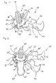
- connection plate 12 that in the Fig. 1 individually and in Fig. 2 together with two identical connection elements 10 ', 10 "shown connecting element 10 has in the middle of the connection plate 12, as well as the connecting plate 12 itself circular opening 14 through which, as in the Fig. 1 and 2 represented, a ground bolt 30 can be inserted.
- the symmetry axis m of the ground bolt then extends axially to the connection plate 12 through the center thereof.
- a total of eight latching recesses 17, 18, 19 are disposed on a concentric with this opening 14 circle, all of which have the shape of circular ring sections with rounded corners.
- the distance between two adjacent latching recesses 17, 18, 19 is the same in each case, so that therefore two adjacent latching recesses 17, 18, 19 are offset in each case by an angle of approximately 45 ° radially to each other.
- each two adjacent, ie a total of four, recesses 18 formed on the facing in the direction of the central opening 14 side of the recess 18 with a radially outward pointing latch 20 are provided.
- the thickness of the locking lugs 20 in the axial direction corresponds to the thickness of the connection plate 12 and the width of the locking lugs 20 is about 1/4 to 1/3 of the extension of a recess 18 in the circumferential direction.
- a further latching recess 19 is finally arranged, which has a latching projection 22 provided with an opening 24.
- the latching projections 22 in the two pairs of locking recesses 19 which are likewise opposite one another extend from the inner sides of the latching recesses 19 pointing in the direction of the opening 14 in the connection plate 12 initially in the plane of the connection plate 12 and then extend in the axial direction perpendicular to this plane opposite to the raised wall portions 40 of the receiving area 16, ie in the Fig. 1 and 2 downward.
- the opening 24 formed in the latching projections 22 has a rectangular cross section and is dimensioned such that essentially only one frame-like edge remains of the latching projections 22.
- the width in the circumferential direction of the openings 24 of the connection plate 12 corresponds to the width of the locking lugs 20 or is slightly larger than this, so that the locking lugs 20, as will be explained later, can engage in the openings 24.
- a total cylindrical ground bolt 30 is provided with a thread 32 for a nut and has at its in the Fig. 1 and 2 almost completely of the or the connecting elements 10, 10 ', 10 "hidden underside an octagonal, pedestal-like foot 34, which is an anti-rotation of a plugged onto the bolt 30th Connection element 10 allows.
- This rotation is effected by the interaction of the octagonal foot 34 with the locking projections 22 described above, which are provided in the two locking recesses 19 formed in the connection plate 12.
- the diameter of the octagonal foot 34 and the position and shape of the locking projections 22 are chosen so that, as in Fig.
- the two locking projections 22 each outside the side surfaces of the octagonal foot 34 abut.
- the connecting element 10 In order to obtain a suitable angular position, the connecting element 10 must be aligned when plugging onto the bolt 30 so that the eight side surfaces of the foot 34 are each aligned with a latching recess 17, 18, 19 of the connecting element 10. In this position, the connecting element 10 is rotationally fixed on the foot 34 of the bolt 30 and is held by the two locking projections 22 in this position.
- eight different angular positions between the foot 34 and a connection element 10 are possible.
- connection elements 10, 10 ', 10 are to be connected to a ground pin 30, then either a plurality of such connection elements 10, 10 ', 10 "successively plugged onto a ground pin 30 and locked against rotation with each other, or you put first several connection elements 10, 10', 10" on each other, so that they lock against each other in a rotationally fixed manner, and then fixes the entire assembly on the ground bolt 30.
- the latter procedure is particularly advantageous when the ground bolt 30 is in a motor vehicle due to the cramped conditions.
- Fig. 2 Three similar connection elements 10, 10 ', 10 ", the in Fig. 1 Corresponding connection element 10 correspond, are attached to a common ground pin 30.
- the connection plates 12, 12 ', 12 "of the three connection elements 10, 10', 10" are thus coaxial with each other and are each offset radially to each other.
- the lowermost connecting element 10 is non-rotatably connected via the locking projections 22 with the ground pin 30, as it is in Fig. 1 is shown.
- the middle connection element 10 ' which is sandwiched between the two other connection elements 10, 10', is in turn connected in a rotationally fixed manner to the connection element 10 underneath and radially offset by 45 ° in the counterclockwise direction with respect to the connection element 10.
- a third connection element 10 is connected to the middle connection element 10 'rotatably locked and offset in relation to this by 90 ° clockwise radially.
- the latching projections 22 "of the uppermost connection element 10" can engage, for example, in underlying latching recesses 17 ', 18', optionally one in the latching recess 18 'trained locking lug 20' in the opening 24 "in the locking projection 22" engages.
- connecting elements 10, 10 ', 10 have only a pair of opposing locking recesses 19, 19", in which corresponding latching projections 22, 22 "are provided, a connection element 10' so in six different angular positions corresponding to the six remaining latching recesses 17, 18, each in the Fig. 2 invisible locking projections of the connecting element 10 'can record, placed on a similar connection element 10 and locked in rotation with this.
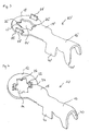
- Fig. 3 is another embodiment of a connecting element 10 'shown, this compared to the representation in the Fig. 1 and 2 is rotated about its longitudinal axis, so that the raised wall portions 40 'of the receiving area 16' downwards instead of upward.
- the basic shape with the circular connection plate 12 ', the transition region 15' and the receiving region 16 ' is the same as in the Fig. 1 and 2 illustrated embodiment.
- the central opening 14 'in the connection plate 12' is not circular, but extends in the longitudinal direction in the same direction as the connection region 16 'and has on the longitudinal sides in each case a bulge 11' for receiving the ground bolt 30.
- the locking lugs 26 extend over 1/4 to 1/3 of the length of the transverse side of the opening 14 and are slightly tapered in the direction of the center of the opening 14 '.
- connection element 10 ' On the outside, two mutually opposite rectangular recesses 29 'are provided on the connecting plate 12', which lie at the level of the bulges 11 'of the opening 14'. In these recesses 29 'an elastic gripping tongue 28' is formed in each case.
- a further connecting element 10 is shown, which in conjunction with the in Fig. 3 shown connecting element according to the invention can be used.
- the receiving area 16 with its raised walls 40, the transition area 15 and the contour of the connecting plate 12 it corresponds to the in Fig. 3 illustrated connection element 10 '.
- a locking projection 22 is formed with a rectangular opening 24 formed therein in each case.
- These locking projections 22 are similar to those in the Fig. 1 They also extend initially approximately in the plane of the terminal plate 12 and then axially in relation to the terminal plate 12 in the direction opposite the raised walls 40 of the receiving area 16 opposite direction. Through the openings 24, the two locking projections 22 also receive here a frame-like shape.
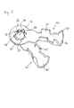
- Fig. 5 are the two in the 3 and 4 shown connecting elements 10 ', 10 now shown mounted together, wherein the two connecting elements 10', 10 in comparison to the illustration of 3 and 4 rotated about its longitudinal axis by 180 °, so that the raised walls 40 ', 40 of the receiving areas 16', 16 point upward. That in the Fig. 3 illustrated connection element 10 'is below the in Fig. 4 The respective openings 14 ', 14 of the two connection elements 10', 10 are aligned with each other so that the locking projections 22 of the overhead connection element 10 lie on the transverse sides of the opening 14 of the lower locking element 10 'and there the locking lugs 26th 'overlap so that they lie in the openings 24 of the locking projections 22.
- the locking lugs 26 of the upper connecting element 10 are located centrally on a radially outside of the bulges 11 lying portion of the connection plate 12 'of the lower locking element 10' and contribute in this case, nothing to the latching.
Abstract
Description
Die vorliegende Erfindung betrifft ein elektrisches Anschlusselement zum Verbinden eines elektrischen Leiters mit einem Bolzen, insbesondere einem Massebolzen. Solche Anschlusselemente werden auch als Kabelschuhe bezeichnet. Sie werden unter anderem häufig in Kraftfahrzeugen verwendet, wobei meistens mehrere solche Anschlusselemente mit einem gemeinsamen Massebolzen verbunden werden.The present invention relates to an electrical connection element for connecting an electrical conductor to a bolt, in particular a ground bolt. Such connection elements are also referred to as cable lugs. Among other things, they are frequently used in motor vehicles, wherein usually several such connection elements are connected to a common ground bolt.
Aus dem Stand der Technik sind Kabelschuhe bekannt, bei denen zum Anschließen des elektrischen Leiters an das Anschlusselement ein rinnenartiger lang gestreckter Aufnahmebereich mit hochgezogenen Wandbereichen dient, in dem der elektrische Leiter durch Herstellen einer Crimpverbindung befestigt werden kann. Zum Anschließen des Anschlusselementes an den bereits erwähnten Massebolzen dient bei aus dem Stand der Technik bekannten Kabelschuhen häufig eine Öffnung, mit der der Kabelschuh auf den Massebolzen aufgesteckt werden kann, wobei diese Öffnung im Allgemeinen zentral in einer Anschlussplatte angeordnet ist, die sich an den lang gestreckten Aufnahmebereich anschließt.Cable lugs are known from the prior art, in which for connecting the electrical conductor to the connection element, a groove-like elongated receiving area with raised wall areas, in which the electrical conductor can be attached by producing a crimp connection. For connecting the connecting element to the above-mentioned ground bolt is often used in known from the prior art cable lugs an opening with which the cable lug can be plugged onto the ground bolt, said opening is generally arranged centrally in a connection plate, which is located on the long elongated receiving area connects.
Der Massebolzen ist üblicherweise mit einem Gewinde versehen, auf dem eine Mutter aufgeschraubt werden kann, nachdem einer oder mehrere Kabelschuhe mit ihrer bereits erwähnten Öffnung auf den Bolzen aufgesteckt worden sind. Wenn mehrere Kabelschuhe übereinander auf einen gleichen Massebolzen aufgesteckt werden sollen, so ordnet man diese aus Platzgründen vorzugsweise radial zueinander versetzt an. Die Montage der einzelnen Kabelschuhe mit den bereits daran gecrimpten Leitern an dem Massebolzen kann aber gerade in einem Kraftfahrzeug aufgrund der dort herrschenden Enge mühselig und zeitaufwendig sein. Insbesondere wenn mehrere Kabelschuhe an dem Bolzen befestigt werden sollen, aber auch schon bei der Befestigung eines einzelnen Kabelschuhs, tritt zudem das Problem auf, dass der Kabelschuh beim Anziehen der Mutter durch die entstehende Reibung ebenfalls in Bezug auf den Bolzen gedreht wird, was nicht erwünscht ist, da dies im schlimmsten Fall dazu führen kann, dass sich der elektrische Leiter aus der Crimpverbindung löst.The ground bolt is usually provided with a thread on which a nut can be screwed after one or more lugs have been plugged with their aforementioned opening on the bolt. If several lugs on top of each other are to be plugged onto a same ground bolt, so you assigns them for reasons of space preferably radially offset from each other. The assembly of individual lugs with the already crimped on it conductors on the ground bolt but can be troublesome and time-consuming just in a motor vehicle due to the prevailing narrowness. In particular, when several lugs to be attached to the bolt, but even in the attachment of a single lug, also the problem arises that the cable lug is tightened when tightening the nut by the resulting friction also with respect to the bolt, which is not desirable is, because in the worst case this can lead to the fact that the electrical conductor comes loose from the crimped connection.
Aus dem Stand der Technik sind bereits Anschlusselemente der eingangs genannten Art bekannt, die mit Rastelementen versehen sind, welche dazu dienen, zwei axial aufeinander angeordnete Anschlusselemente drehfest miteinander zu verbinden.From the prior art connection elements of the type mentioned are already known, which are provided with locking elements, which serve to connect two axially mutually arranged connection elements rotatably with each other.
So offenbart die
Es ist daher die Aufgabe der vorliegenden Erfindung, ein elektrisches Anschlusselement der eingangs erwähnten Art zur Verfügung zu stellen, welches eine elektrisch und mechanisch zuverlässige Montage mehrerer Anschlusselemente an einem Bolzen auf beschleunigte und vereinfachte Weise ermöglicht. Insbesondere soll vermieden werden, dass der Kabelschuh beim Anziehen der Mutter durch die entstehende Reibung ebenfalls in Bezug auf den Bolzen gedreht wird.It is therefore an object of the present invention to provide an electrical connection element of the type mentioned above, which enables an electrically and mechanically reliable mounting of several connection elements on a bolt in an accelerated and simplified manner. In particular, it should be avoided that the cable lug is also rotated when tightening the nut by the resulting friction with respect to the bolt.
Diese Aufgabe wird erfindungsgemäß durch ein elektrisches Anschlusselement gemäß Anspruch 1 gelöst. Erfindungsgemäß weist das Anschlusselement eine Verdrehsicherung auf, die geeignet ist, mit dem durch die zentrale Öffnung verlaufenden Bolzen zusammenzuwirken.This object is achieved by an electrical connection element according to claim 1. According to the invention, the connection element has an anti-twist device which is suitable for interacting with the bolt passing through the central opening.
Die außenseitig von der zentralen Öffnung vorgesehenen Rastelemente können verschiedenartig ausgebildet sein, haben aber unabhängig von der konkreten Ausführungsform alle gemeinsam, dass, wenn zwei identische oder mit jeweils einander korrespondierenden Rastelementen versehene Anschlusselemente axial aufeinander gesetzt werden, die Rastelemente der beiden Anschlusselemente miteinander verrasten. Ein Verdrehen der beiden Anschlusselemente gegeneinander ist dann nicht mehr möglich. Die Verrastung der Anschlusselemente miteinander kann bereits vor dem Aufsetzen derselben auf den Massebolzen hergestellt werden, so dass die anschließende Montage an dem Bolzen in einem einzigen Schritt erfolgen kann.The locking elements provided on the outside of the central opening may be designed differently, but all have in common, regardless of the specific embodiment, that when two identical or provided with each corresponding locking elements connecting elements are set axially against each other, the locking elements of the two connection elements lock together. A twisting of the two connection elements against each other is then no longer possible. The locking of the connecting elements together can be made before placing them on the ground bolt, so that the subsequent mounting on the bolt can be done in a single step.
Bevorzugte Ausführungsformen der Erfindung sind in den Unteransprüchen und in der nun folgenden Beschreibung sowie der Beschreibung der beigefügten Figuren beschrieben.Preferred embodiments of the invention are described in the subclaims and in the description which follows, as well as the description of the attached figures.
Nach einer besonders bevorzugten Ausführungsform der Erfindung wird die Verdrehsicherung von einem der Rastelemente gebildet. Das Verdrehen des Anschlusselementes relativ zu dem durch die zentrale Öffnung verlaufenden Bolzen wird also durch ein Rastelement, welches gleichzeitig der Verrastung zweier elektrischer Anschlusselemente miteinander dient, verhindert. Wenigstens eines der Rastelemente, welche mit korrespondierenden Rastelementen an einem zweiten Anschlusselement verrasten können, besitzt also eine Doppelfunktion. Bei dieser Ausführungsform der Erfindung ist kein besonders ausgebildetes Anschlusselement nötig, welches die drehfeste Verbindung mit dem Bolzen herstellt, sondern die Anschlusselemente können alle gleich ausgebildet sein und, je nach ihrer Lage bezüglich eventueller anderer Anschlusselemente, entweder eine drehfeste Verbindung mit einem darüber oder darunter liegenden weiteren Anschlusselement oder eine drehfeste Verbindung mit dem Bolzen herstellen.According to a particularly preferred embodiment of the invention, the rotation of one of the locking elements is formed. The rotation of the connection element relative to the bolt passing through the central opening is thus prevented by a latching element which simultaneously serves to latch two electrical connection elements together. At least one of the latching elements, which can latch with corresponding latching elements on a second connection element, thus has a double function. In this embodiment of the invention, no specially designed connection element is necessary which makes the non-rotatable connection with the bolt, but the connection elements can all be of the same design and, depending on their location with respect to any other connection elements, either a rotationally fixed connection with an overlying or underlying other connection element or a rotationally fixed connection with the bolt.
Vorzugsweise weisen die Rastelemente Rastausnehmungen auf, wobei diese Rastausnehmungen darin ausgebildete, radial nach außen weisende Rastnasen umfassen können. Durch solche Rastausnehmungen - mit oder ohne darin ausgebildete Rastnase - können korrespondierende Rastelemente, welche an einem anderen Anschlusselement ausgebildet sind, hindurchgesteckt werden. Die in den Rastausnehmungen ausgebildeten Rastnasen bieten zahlreiche Möglichkeiten zur Herstellung einer Rastverbindung mit einem weiteren Anschlusselement.The latching elements preferably have latching recesses, wherein these latching recesses may comprise latching lugs formed radially outwardly. By such locking recesses - with or without locking lug formed therein - corresponding locking elements, which are formed on another connection element, are inserted therethrough. The latching lugs formed in the latching recesses offer numerous possibilities for producing a latching connection with a further connecting element.
Die Rastelemente können auch in Rastausnehmungen angeordnete, axial vorstehende und mit einer Öffnung versehene Rastvorsprünge umfassen. Solche Vorsprünge können dann beispielsweise in Rastausnehmungen in einem darunter oder darüber liegenden Anschlusselement eingreifen, und auf diese Weise eine drehfeste Verbindung zwischen zwei Anschlusselementen herstellen. Die Öffnung in den Rastvorsprüngen kann wiederum dazu dienen, eine radial nach außen weisende Rastnase, wie sie oben erwähnt wurde, aufzunehmen, so dass auch mit Rastausnehmungen, welche eine solche Rastnase aufweisen, eine stabile drehfeste Verbindung hergestellt werden kann.The locking elements may also comprise locking recesses arranged in axially projecting and provided with an opening locking projections. Such projections can then engage, for example, in recesses in an underlying or overlying connection element, and in this way produce a rotationally fixed connection between two connection elements. The opening in the latching projections may in turn serve to receive a radially outwardly facing latching lug, as mentioned above, so that even with latching recesses, which have such a latching lug, a stable rotationally fixed connection can be made.
Gemäß einer weiteren bevorzugten Ausführungsform der Erfindung sind an der Anschlussplatte jeweils zwei identisch ausgebildete Rastelemente symmetrisch in Bezug auf eine durch deren zentrale Öffnung verlaufende axiale Mitte angeordnet. Wenn beispielsweise zwei oder drei verschiedene Typen von Rastelementen in der Anschlussplatte eines Anschlusselementes ausgebildet sind, so führt diese symmetrische Anordnung der Rastelemente dazu, dass zwei identische Anschlusselemente in möglichst vielen unterschiedlichen Winkelpositionen aufeinander gesteckt und miteinander drehfest verrastet werden können.According to a further preferred embodiment of the invention, in each case two identically designed latching elements are arranged symmetrically with respect to an axial center extending through the central opening thereof on the connection plate. If, for example, two or three different types of latching elements are formed in the connection plate of a connection element, this symmetrical arrangement of the latching elements means that two identical connection elements can be plugged on one another in as many different angular positions as possible and locked in rotation with each other.
Vorzugsweise sind an der Anschlussplatte verschiedenartige, um einen bestimmten Winkel radial zueinander versetzt angeordnete Rastelemente vorgesehen, wobei, wenn zwei identische Anschlusselemente um diesen Winkel radial zueinander versetzt axial aufeinander gesetzt werden, die Rastelemente der beiden Anschlusselemente miteinander verrastbar sind. Beispielsweise können zwei verschiedene Typen von Rastelementen unter Bildung eines Kreuzes jeweils einander gegenüberliegend angeordnet sein, so dass jeweils zwei unterschiedliche Rastelemente einander benachbart und um einen Winkel von 90° zueinander versetzt sind. Die Rastelemente können dabei so ausgestaltet sein, dass, wenn zwei derartige Anschlusselemente um 90° zueinander versetzt aufeinander gesetzt werden, jeweils die dann aufeinander liegenden unterschiedlichen Rastelemente miteinander verrasten.Preferably, various, at a certain angle radially offset from one another arranged latching elements are provided on the connection plate, wherein when two identical connection elements are radially offset from each other by this angle axially offset, the locking elements of the two connection elements are locked together. For example, two different types of locking elements to form a cross in each case be arranged opposite one another, so that in each case two different locking elements adjacent to each other and offset by an angle of 90 ° to each other. The latching elements can be designed so that when two such connection elements are offset from one another by 90 ° to each other, each lock the then superposed different locking elements together.
Nach einer weiteren bevorzugten Ausführungsform der Erfindung ist eine Vielzahl von Rastelementen, insbesondere sechs oder acht Rastelemente, mit gleichmäßigen Abständen zwischen zwei benachbarten Rastelementen konzentrisch um die zentrale Öffnung der Anschlussplatte angeordnet.According to a further preferred embodiment of the invention, a plurality of locking elements, in particular six or eight locking elements, arranged at uniform intervals between two adjacent locking elements concentrically around the central opening of the connecting plate.
Der Winkel, um den benachbarte Rastelemente radial zueinander versetzt sind, ist dann ebenfalls jeweils der gleiche. Durch die gleichmäßigen Abstände können wie auch im zuvor beschriebenen Fall um einen geeigneten Winkel, beispielsweise den Versatzwinkel zwischen benachbarten Rastelementen, radial zueinander versetzte Anschlusselemente so aufeinander gesetzt werden, dass ihre jeweiligen Rastelemente aufeinander zu liegen kommen, und somit miteinander verrasten können. Bei geeigneter Anordnung und Wahl von Rastelementen kann bei dieser Ausführungsform aus einer Vielzahl von verschiedenen Winkelpositionen für aufeinander gesteckte und drehfest miteinander verrastete Anschlusselemente gewählt werden.The angle at which the adjacent latching elements are radially offset from one another is then also the same in each case. As a result of the uniform distances, as in the case described above, connecting elements which are radially offset from one another by a suitable angle, for example the offset angle between adjacent latching elements, can be placed on top of one another such that their respective latching elements come to rest on one another and thus latch together. With a suitable arrangement and choice of locking elements can be selected in this embodiment from a variety of different angular positions for successive inserted and rotatably locked together connection elements.
Nach einer bevorzugten Ausführungsform der Erfindung sind verschiedene Typen von Rastelementen, insbesondere zwei oder drei verschiedene Typen von Rastelementen vorgesehen. Es können beispielsweise zwei verschiedene Typen von Rastelementen vorgesehen sein, die jeweils abwechselnd mit gleichmäßigen Abständen zwischen zwei benachbarten Rastelementen konzentrisch um die zentrale Öffnung der Anschlussplatte angeordnet sind.According to a preferred embodiment of the invention, various types of locking elements, in particular two or three different types of locking elements are provided. For example, two different types of locking elements can be provided, which are each arranged alternately with uniform spacing between two adjacent locking elements concentrically around the central opening of the connecting plate.
Nach einer besonders bevorzugten Ausführungsform der Erfindung ist in der Anschlussplatte eine Vielzahl von rotationssymmetrisch angeordneten, im Wesentlichen gleich geformten Rastausnehmungen ausgebildet, die entweder für sich genommen oder zusammen mit einer Rastnase oder einem Rastvorsprung ein Rastelement bilden. Diese Art der Rastelemente erlaubt eine Kompatibilität verschiedener Typen von Rastelementen jeweils miteinander. Beispielsweise kann ein Rastelement, welches allein aus einer Rastausnehmung besteht, mit einem zweiten Rastelement, welches aus einer ähnlichen Rastausnehmung mit einem Rastvorsprung gebildet ist, verrasten.According to a particularly preferred embodiment of the invention, a plurality of rotationally symmetrically arranged, substantially identically shaped latching recesses are formed in the connection plate, which either taken alone or together with a latching lug or a latching projection form a latching element. This type of locking elements allows compatibility of different types of locking elements each with each other. For example, a latching element, which consists solely of a latching recess, with a second latching element, which is formed from a similar recess with a latching projection, lock.
Nach einer weiteren bevorzugten Ausführungsform der Erfindung können an der zentralen Öffnung der Anschlussplatte außenseitig Rastzungen ausgebildet sein, welche radial nach innen weisen und Rastelemente bilden. Dies ist natürlich nur möglich, wenn der Durchmesser der zentralen Öffnung zumindest in den Bereichen, in denen die Rastzungen ausgebildet sind, größer ist als der Durchmesser des Bolzens, auf den die Anschlussplatte aufgesteckt wird, da sonst die Rastelemente das Aufstecken auf den Bolzen verhindern würden. Beispielweise können, wenn eine kreuzförmige Öffnung in der Anschlussplatte vorgesehen ist, jeweils in den Endbereichen der Arme des Kreuzes außenseitig Rastzungen ausgebildet sein, die dennoch das Aufstecken des Anschlusselementes auf dem Bolzen erlauben, und eine Verrastung mit einem weiteren Anschlusselement ermöglichen.According to a further preferred embodiment of the invention, locking tongues can be formed on the outside at the central opening of the connection plate, which have radially inward and form latching elements. Of course, this is only possible if the diameter of the central opening, at least in the areas in which the latching tongues are formed, is greater than the diameter of the bolt on which the connection plate is plugged, otherwise the latching elements would prevent the plugging onto the bolt , For example, if a cross-shaped opening is provided in the connection plate, latching tongues may be formed on the outside in the end regions of the arms of the cross, which nevertheless permit the attachment of the connection element on the bolt, and allow latching with a further connection element.
Nach einer vorteilhaften Weiterbildung der Erfindung kann die Verdrehsicherung von außenseitig an der Anschlussplatte angeformten elastischen Greifzungen gebildet sein. Diese können beispielsweise an einem Fuß eines Bolzens außenseitig zur Anlage gebracht werden und somit ein Verdrehen des Anschlusselementes in Bezug auf den Fuß verhindern.According to an advantageous embodiment of the invention, the rotation can be formed on the outside of the connection plate integrally formed elastic gripping tongues. These can for example be brought to bear against the outside of a foot of a bolt and thus prevent twisting of the connecting element with respect to the foot.
Der Aufnahmebereich für den elektrischen Leiter ist vorzugsweise im Wesentlichen rinnenförmig ausgebildet und weist hochgezogene Wandbereiche zum Herstellen einer Crimpverbindung auf. Diese Wandbereiche werden während des Crimpvorganges in den rinnenförmigen Aufnahmebereich herunter gedrückt, so dass der Leiter in diesem eingeklemmt wird.The receiving region for the electrical conductor is preferably substantially channel-shaped and has raised wall regions for producing a crimp connection. These wall portions are pressed down during the crimping process in the channel-shaped receiving area, so that the conductor is clamped in this.
Ein derartiger Aufnahmebereich ermöglicht eine einfache und schnelle Montage eines elektrischen Leiters an dem Anschlusselement und ist zudem vergleichsweise einfach herzustellen.Such a receiving area allows a simple and quick installation of an electrical conductor to the connection element and is also relatively easy to manufacture.
Das Anschlusselement ist vorzugsweise einstückig ausgebildet, insbesondere kann es aus einem Metallblech geformt sein. Die einstückige Ausbildung des Anschlusselementes ermöglicht eine günstige Massenproduktion von Anschlusselementen.The connecting element is preferably formed in one piece, in particular it may be formed from a metal sheet. The one-piece design of the connection element enables a favorable mass production of connection elements.
Die Erfindung betrifft zudem eine Kombination aus einem ersten elektrischen Anschlusselement gemäß Anspruch 1 mit einem zweiten elektrischen Anschlusselement. Das zweite elektrische Anschlusselement besitzt erfindungsgemäß ebenso wie das erste elektrische Anschlusselement einen im Wesentliche kreisförmige Anschlussplatte mit einer zentralen Öffnung zum Aufstecken des Anschlusselementes auf den Bolzen und einen in eine radiale Richtung bezüglich der Anschlussplatte lang gestreckten Aufnahmebereich für einen elektrischen Leiter. An der Anschlussplatte des zweiten elektrischen Anschlusselementes sind wenigstens zwei Rastelemente vorgesehen, welche, wenn das zweite Anschlusselement in einer vorbestimmten Winkelposition bezüglich des ersten Anschlusselementes axial auf letzteres aufgesetzt wird, mit korrespondierenden Rastelementen desselben drehfest verrastbar sind. Das zweite elektrische Anschlusselement entspricht also dem ersten Anschlusselement bis auf die bei dem ersten Anschlusselement vorgesehene und bei dem zweiten Anschlusselement fehlende Verdrehsicherung, welche mit dem Bolzen zusammenwirken kann. Das zweite Anschlusselement kann somit zwar keine drehfeste Verbindung mit dem Bolzen herstellen, besitzt aber ansonsten alle Vorteile des bereits beschriebenen Anschlusselementes. Es wird zum Herstellen einer drehfesten Verbindung mit dem Bolzen immer gemeinsam mit einem Anschlusselement verwendet, welches eine Verdrehsicherung aufweist, beispielsweise in Form von außenseitig an der Anschlussplatte ausgebildeten Greifzungen, die mit dem Bolzen zusammenwirken können. Dieses Anschlusselement stellt die drehfeste Verbindung mit dem Bolzen her, und eines oder mehrere Anschlusselemente, die keine solche Verdrehsicherung aufweisen, können nacheinander axial auf dieses erste Anschlusselement aufgesetzt werden und jeweils mit einem darunter liegenden Anschlusselement drehfest verrasten. Man erhält somit einen Stapel von übereinander angeordneten und mit dem Bolzen entweder direkt oder über wenigstens ein darunter liegendes Anschlusselement drehfest verbundenen Anschlusselementen.The invention also relates to a combination of a first electrical connection element according to claim 1 with a second electrical connection element. According to the invention, the second electrical connection element, like the first electrical connection element, has a substantially circular connection plate with a central opening for attaching the connection element to the bolt and an receiving region, elongated in a radial direction relative to the connection plate, for an electrical conductor. At least two locking elements are provided on the connection plate of the second electrical connection element, which, when the second connection element is placed axially on the latter in a predetermined angular position with respect to the first connection element, can be locked in a rotationally fixed manner with corresponding latching elements. The second electrical connection element thus corresponds to the first connection element except for the one provided at the first connection element and missing in the second connection element anti-rotation, which can cooperate with the bolt. Although the second connection element can thus produce no rotationally fixed connection with the bolt, but otherwise has all the advantages of the connection element already described. It is used for producing a rotationally fixed connection with the bolt always together with a connection element which has an anti-rotation, for example in the form of externally formed on the connection plate gripping tongues, which can cooperate with the bolt. This connection element establishes the non-rotatable connection with the bolt, and one or more connection elements, which have no such rotation, can be successively placed axially on this first connection element and each lock with a lower connection element rotationally fixed. One thus obtains a stack of superimposed and rotatably connected to the bolt either directly or via at least one underlying connection element connection elements.
Nach einer besonders bevorzugten Ausführungsform der Erfindung ist die zentrale Öffnung des zweiten elektrischen Anschlusselementes im Wesentlichen kreuzförmig, und an den vier Armen des Kreuzes ist jeweils ein Rastelement angeordnet. Je nach Wahl und Anordnung der Rastelemente können zwei identische Anschlusselemente bei dieser Ausführungsform zumindest in zwei verschiedenen Positionen, nämlich mit einem radialen Versatz von 90° oder von 270°, aufeinander gesetzt und miteinander verrastet werden.According to a particularly preferred embodiment of the invention, the central opening of the second electrical connection element is substantially cross-shaped, and on the four arms of the cross a latching element is arranged in each case. Depending on the choice and arrangement of the locking elements, two identical connection elements in this embodiment, at least in two different positions, namely with a radial offset of 90 ° or 270 °, placed on each other and locked together.
Im Folgenden soll die Erfindung anhand von drei verschiedenen bevorzugten Ausführungsformen und unter Bezugnahme auf die beigefügten Figuren genauer beschrieben werden. Die Figuren zeigen im Einzelnen:
- Fig. 1
- eine perspektivische Ansicht eines auf einen Bolzen aufgesteckten Anschlusselementes gemäß einer ersten Ausführungsform der Erfindung,
- Fig. 2
- eine perspektivische Ansicht der Anordnung aus der
Fig. 1 mit zwei weiteren auf den Bolzen aufgesteckten Anschlusselementen, - Fig. 3
- eine perspektivische Ansicht eines Anschlusselementes gemäß einer zweiten Ausführungsform,
- Fig. 4
- eine perspektivische Ansicht eines zweiten Anschlusselementes, welches mit dem in
Fig. 3 dargestellten Anschlusselement kombiniert werden kann, - Fig. 5
- eine perspektivische Ansicht der Anschlusselemente aus den
Fig. 3 und 4 in miteinander verrastetem Zustand.
- Fig. 1
- a perspective view of a plugged on a bolt connection element according to a first embodiment of the invention,
- Fig. 2
- a perspective view of the arrangement of the
Fig. 1 with two further connection elements plugged onto the bolt, - Fig. 3
- a perspective view of a connection element according to a second embodiment,
- Fig. 4
- a perspective view of a second connection element, which with the in
Fig. 3 illustrated connecting element can be combined - Fig. 5
- a perspective view of the connection elements of the
3 and 4 in a locked state.
Alle in den
Der Aufnahmebereich 16, 16', 16" ist bei allen dargestellten Anschlusselementen 10, 10', 10" rinnenförmig ausgebildet und besitzt beidseitig hochgezogene Wandbereiche 40, 40', 40", welche das Herstellen einer Crimpverbindung mit einem in dem Aufnahmebereich 16, 16', 16" liegenden, in den Figuren nicht dargestellten elektrischen Leiter erlauben.The receiving
Bei den in den
Die in den
Das in der
Um die zentrale Öffnung 14 herum sind auf einem mit dieser Öffnung 14 konzentrischen Kreis insgesamt acht Rastausnehmungen 17, 18, 19 angeordnet, die alle die Form von Kreisringabschnitten mit abgerundeten Ecken besitzen. Der Abstand zwischen zwei benachbarten Rastausnehmungen 17, 18, 19 ist jeweils der gleiche, so dass also zwei benachbarte Rastausnehmungen 17, 18, 19 jeweils um einen Winkel von etwa 45° radial zueinander versetzt sind.Around the
Es sind insgesamt drei verschiedene Typen von Rastausnehmungen 17, 18, 19 vorgesehen, wobei sich immer zwei gleichartige Rastausnehmungen 17, 18, 19 paarweise gegenüberliegen. In der einfachsten Form besitzen die Rastausnehmungen 17 keine weiteren Rastelemente. Genau zwei solche eine einfache Ausnehmung bildenden Rastausnehmungen 17 sind sich einander gegenüberliegend vorgesehen.There are a total of three different types of locking recesses 17, 18, 19 are provided, with always two
Im Uhrzeigersinn neben diesen beiden einfachen Rastausnehmungen 17 sind jeweils zwei nebeneinander liegende, d.h. insgesamt vier, Rastausnehmungen 18 ausgebildet, die an der in Richtung der zentralen Öffnung 14 weisenden Seite der Rastausnehmung 18 mit einer radial nach außen weisenden Rastnase 20 versehen sind. Die Dicke der Rastnasen 20 in axialer Richtung entspricht dabei der Dicke der Anschlussplatte 12 und die Breite der Rastnasen 20 beträgt etwa 1/4 bis 1/3 der Erstreckung einer Rastausnehmung 18 in Umfangsrichtung.Clockwise next to these two
Jeweils zwischen einer der einfachen Rastausnehmungen 17 und einer der mit einer Rastnase 20 versehenen Rastausnehmungen 18 ist schließlich noch eine weitere Rastausnehmung 19 angeordnet, die einen mit einer Öffnung 24 versehenen Rastvorsprung 22 aufweist. Die Rastvorsprünge 22 in den beiden sich ebenfalls wieder paarweise gegenüber liegenden Rastausnehmungen 19 erstrecken sich von den in Richtung der Öffnung 14 in der Anschlussplatte 12 weisenden Innenseiten der Rastausnehmungen 19 aus zunächst in der Ebene der Anschlussplatte 12 und verlaufen dann senkrecht zu dieser Ebene in axiale Richtung entgegengesetzt zu den hochgezogenen Wandbereichen 40 des Aufnahmebereiches 16, d.h. in den
Der in den
Wenn mehrere Leiter mit einem Massebolzen 30 verbunden werden sollen, dann können entweder mehrere derartige Anschlusselemente 10, 10', 10" nacheinander auf einen Massebolzen 30 aufgesteckt und miteinander drehfest verrastet werden, oder aber man steckt zunächst mehrere Anschlusselemente 10, 10', 10" aufeinander, so dass sie drehfest miteinander verrasten, und befestigt danach die gesamte Anordnung auf dem Massebolzen 30. Letztere Vorgehensweise ist insbesondere dann, wenn der Massebolzen 30 sich in einem Kraftfahrzeug befindet, aufgrund der beengten Verhältnisse häufig vorteilhafter. Unabhängig von der gewählten Vorgehensweise erhält man eine Anordnung, wie sie beispielhaft in
Das zuunterst liegende Anschlusselement 10 ist dabei über die Rastvorsprünge 22 drehfest mit dem Massebolzen 30 verbunden, wie es in
Da die in den
In
Die zentrale Öffnung 14' in der Anschlussplatte 12' ist allerdings nicht kreisförmig, sondern erstreckt sich in Längsrichtung in die gleiche Richtung wie der Anschlussbereich 16' und besitzt an den Längsseiten jeweils eine Ausbuchtung 11' zur Aufnahme des Massebolzens 30. An den beiden Querseiten der lang gestreckten Rastausnehmung 14' sind jeweils in Richtung des Zentrums der Öffnung 14' weisende Rastnasen 26' angeformt, welche eine ähnliche Form wie die Rastnasen 20 bei dem in der
Außenseitig sind an der Anschlussplatte 12' zwei einander gegenüberliegende rechteckige Rastausnehmungen 29' vorgesehen, welche auf Höhe der Ausbuchtungen 11' der Öffnung 14' liegen. In diesen Rastausnehmungen 29' ist jeweils eine elastische Greifzunge 28' angeformt. Die gekrümmt ausgebildeten elastischen Greifzungen 28' weisen dabei in
In
An den Enden von zwei einander gegenüberliegenden Armen des Kreuzes sind Rastnasen 26 ausgebildet, welche den Rastnasen 26' an den Querenden der Rastausnehmung 14' des in
In
Da sich die Öffnung 14 bei dem in
- 10, 10', 10"10, 10 ', 10 "
- Anschlusselementconnecting element
- 11'11 '
- Ausbuchtungen in Öffnung 14'Bulges in opening 14 '
- 12, 12', 12"12, 12 ', 12 "
- Anschlussplatteconnecting plate
- 14, 14', 14"14, 14 ', 14 "
-
Öffnung in der Anschlussplatte 12, 12', 12"Opening in the
connection plate - 15, 15', 15"15, 15 ', 15 "
- ÜbergangsbereichTransition area
- 16, 16', 16"16, 16 ', 16 "
- Aufnahmebereichreception area
- 17, 17', 17"17, 17 ', 17 "
- Rastausnehmungenrecesses
- 18, 18', 18"18, 18 ', 18 "
- Rastausnehmungenrecesses
- 19, 19', 19"19, 19 ', 19 "
- Rastausnehmungenrecesses
- 20, 20', 20"20, 20 ', 20 "
-
Rastnasen in Rastausnehmungen 18, 18', 18"Locking lugs in locking
recesses - 22, 22', 22"22, 22 ', 22 "
-
Rastvorsprünge in Rastausnehmungen 19, 19", 19"Locking projections in
recesses - 24, 24', 24"24, 24 ', 24 "
- Öffnungen in den Rastvorsprüngen, 22, 22', 22"Openings in the latching projections, 22, 22 ', 22 "
- 26, 26'26, 26 '
-
Rastnasen an Öffnung 14, 14'Latches on
opening 14, 14 ' - 28'28 '
- Greifzungengrip tongues
- 29'29 '
- außenseitige Rastausnehmungen in Anschlussplatte 12'Outside recesses in connection plate 12 '
- 3030
- Massebolzenearth stud
- 3232
- Gewindethread
- 3434
-
Fußteil des Bolzens 30Foot part of the
bolt 30 - 40, 40', 40"40, 40 ', 40 "
- hochgezogene Wandbereicheraised wall areas
- mm
- Mittelachsecentral axis
Claims (15)
- An electrical connector element (10, 10', 10") for the connection of an electrical lead to a bolt (30), in particular to a ground bolt, comprising a substantially circular connector plate (12, 12', 12") with a central opening (14, 14') for plugging the connector element (10, 10', 10") onto the bolt (30), and a receiving region (16, 16', 16") for an electrical lead, said receiving region being elongated in a radial direction with respect to the connector plate (12, 12', 12"), with at least two latch elements (17, 17", 20, 20', 20", 22, 22", 26') being provided at the connector plate (12, 12', 12") outside of the central opening (14, 14') which are rotationally fixedly latchable to corresponding latch elements (17, 17", 20, 20', 20", 22, 22", 26') of the first connector element (10, 10', 10") when a further connector element (10, 10', 10") is mounted axially onto said first connector element (10, 10', 10") in a predetermined angular position with respect to the first connector element (10, 10', 10"),
characterized in that
the connector element (10, 10', 10") has a security against rotation (22, 22", 28') which is suitable to cooperate with the bolt (30) extending through the central opening (14). - An electrical connector element (10, 10', 10") in accordance with claim 1, characterized in that the security against rotation is formed by one of the latch elements (22, 22").
- An electrical connector element (10, 10', 10") in accordance with claim 1 or claim 2, characterized in that the latch elements include latch recesses (17, 17", 18, 18"), in particular with radially outwardly facing latch noses (20, 20', 20") formed therein.
- An electrical connector element (10, 10', 10") in accordance with any one of the preceding claims, characterized in that the latch elements include axially projecting latch projections (22, 22") provided with an opening (24, 24") and arranged in latch recesses (19, 19").
- An electrical connector element (10, 10', 10") in accordance with any one of the preceding claims, characterized in that two identically formed latch elements (17, 17", 20, 20', 20", 22, 22", 26') are in each case arranged symmetrically on the connector plate (12, 12', 12") with respect to an axial central axis (m) extending through its central opening (14, 14').
- An electrical connector element (10, 10', 10") in accordance with any one of the preceding claims, characterized in that different types of latch elements (17, 17", 20, 20', 20", 22, 22") are provided at the connector plate (12, 12', 12") and are arranged radially offset to one another by a specific angle, with the latch elements (17, 17", 20, 20', 20", 22, 22") of the two connector elements (10, 10', 10") being latchable to one another when two identical connector elements (10, 10', 10") are mounted axially on one another radially offset to one another by this angle.
- An electrical connector element (10, 10', 10") in accordance with any one of the preceding claims, characterized in that a plurality of latch elements (17, 17", 20, 20', 20", 22, 22"), in particular six or eight latch elements (17, 17", 20, 20', 20", 22, 22"), are arranged concentrically around the central opening (14) of the connector plate (12, 12', 12") with uniform intervals between two adjacent latch elements (17, 17", 20, 20', 20", 22, 22").
- An electrical connector element (10, 10', 10") in accordance with any one of the preceding claims, characterized in that different types of latch elements (17, 17", 20, 20', 20", 22, 22"), in particular two or three different types of latch elements, are provided.
- An electrical connector element (10, 10', 10") in accordance with any one of the preceding claims, characterized in that a plurality of rotationally symmetrically arranged, substantially like-shaped latch recesses (17, 17", 18, 18", 19, 19") are formed in the connector plate (12, 12', 12") and form a latch element either on their own or together with a latch nose (20, 20', 20") or with a latch projection (22, 22").
- An electrical connector element (10') in accordance with any one of the preceding claims, characterized in that latching tongues (26') are formed outside of the central opening (14') which face radially inwardly and form latch elements.
- An electrical connector element (10, 10', 10") in accordance with any one of the preceding claims, characterized in that the security against rotation is formed by gripping tongues (28') shaped at the outside on the connector plate (12').
- An electrical connector element (10, 10', 10") in accordance with any one of the preceding claims, characterized in that the receiving region (16, 16', 16") for the electrical lead is made substantially groove-shaped and has raised wall regions (40, 40', 40") to establish a crimp connection.
- An electrical connector element (10, 10', 10") in accordance with any one of the preceding claims, characterized in that it is made in one piece.
- A combination of a first electrical connector element (10') in accordance with any one of the preceding claims and of a second electrical connector element (10) comprising a substantially circular connector plate (12) with a central opening (14) for plugging the connector element (10) onto the bolt (30), and a receiving region (16) for an electrical lead, said receiving region being elongated in a radial direction with respect to the connector plate (12), with at least two latch elements (22, 26) being provided outside of the central opening (14) on the connector plate (12) which are rotationally fixedly latchable to corresponding latch elements (26'), when the second connector element (10) is axially mounted onto the first connector element (10') in a predetermined angular position with respect to the first connector element (10').
- A combination in accordance with claim 14, characterized in that the central opening (14) of the second electrical connector element (10) is essentially cruciform and a respective latch element (22, 26) is arranged at each of the four arms of the cross.
Priority Applications (3)
| Application Number | Priority Date | Filing Date | Title |
|---|---|---|---|
| DE502005003207T DE502005003207D1 (en) | 2005-07-21 | 2005-07-21 | Electrical connection element |
| EP05015903A EP1746686B1 (en) | 2005-07-21 | 2005-07-21 | Electrical terminal |
| AT05015903T ATE389247T1 (en) | 2005-07-21 | 2005-07-21 | ELECTRICAL CONNECTION ELEMENT |
Applications Claiming Priority (1)
| Application Number | Priority Date | Filing Date | Title |
|---|---|---|---|
| EP05015903A EP1746686B1 (en) | 2005-07-21 | 2005-07-21 | Electrical terminal |
Publications (2)
| Publication Number | Publication Date |
|---|---|
| EP1746686A1 EP1746686A1 (en) | 2007-01-24 |
| EP1746686B1 true EP1746686B1 (en) | 2008-03-12 |
Family
ID=35079238
Family Applications (1)
| Application Number | Title | Priority Date | Filing Date |
|---|---|---|---|
| EP05015903A Active EP1746686B1 (en) | 2005-07-21 | 2005-07-21 | Electrical terminal |
Country Status (3)
| Country | Link |
|---|---|
| EP (1) | EP1746686B1 (en) |
| AT (1) | ATE389247T1 (en) |
| DE (1) | DE502005003207D1 (en) |
Cited By (1)
| Publication number | Priority date | Publication date | Assignee | Title |
|---|---|---|---|---|
| DE102016200363A1 (en) | 2016-01-14 | 2017-07-20 | Lisa Dräxlmaier GmbH | contact element |
Families Citing this family (3)
| Publication number | Priority date | Publication date | Assignee | Title |
|---|---|---|---|---|
| EP2009744A1 (en) * | 2007-06-28 | 2008-12-31 | Delphi Technologies, Inc. | Fastening system for fastening cable shoe |
| EP2065982B1 (en) * | 2007-11-30 | 2010-07-14 | Delphi Technologies, Inc. | Electric connecting element |
| EP2555332B1 (en) * | 2011-08-01 | 2014-03-19 | Yazaki Europe Ltd | Contact element |
Family Cites Families (2)
| Publication number | Priority date | Publication date | Assignee | Title |
|---|---|---|---|---|
| JP2592690Y2 (en) * | 1993-12-10 | 1999-03-24 | 住友電装株式会社 | Terminal fitting |
| US5759056A (en) * | 1996-07-24 | 1998-06-02 | Yazaki Corporation | Interlockable eyelet terminal |
-
2005
- 2005-07-21 EP EP05015903A patent/EP1746686B1/en active Active
- 2005-07-21 AT AT05015903T patent/ATE389247T1/en not_active IP Right Cessation
- 2005-07-21 DE DE502005003207T patent/DE502005003207D1/en active Active
Cited By (2)
| Publication number | Priority date | Publication date | Assignee | Title |
|---|---|---|---|---|
| DE102016200363A1 (en) | 2016-01-14 | 2017-07-20 | Lisa Dräxlmaier GmbH | contact element |
| DE102016200363B4 (en) * | 2016-01-14 | 2018-02-15 | Lisa Dräxlmaier GmbH | contact element |
Also Published As
| Publication number | Publication date |
|---|---|
| ATE389247T1 (en) | 2008-03-15 |
| DE502005003207D1 (en) | 2008-04-24 |
| EP1746686A1 (en) | 2007-01-24 |
Similar Documents
| Publication | Publication Date | Title |
|---|---|---|
| EP3627625B1 (en) | Connecting terminal | |
| EP2593994B1 (en) | Housing, in particular for an electrical cable connection | |
| WO2006133925A1 (en) | Electrical plug-in connection, plug part, and socket part | |
| EP3796482B1 (en) | Connector comprising a protective circuit bridge | |
| WO2013135467A1 (en) | Mounting unit and method for mounting a mounting rail on a mounting panel for a switchgear cabinet | |
| EP1177387A1 (en) | Connecting element | |
| CH624795A5 (en) | ||
| EP3843221A1 (en) | Supporting frame for a connector | |
| EP1746686B1 (en) | Electrical terminal | |
| DE3817079C2 (en) | Positive connection between two sheet metal parts of a vehicle and process for their manufacture | |
| EP1101957B1 (en) | Assembly washer for a vehicle component | |
| EP3522301B1 (en) | Connection device and power supply assembly | |
| EP0681343A2 (en) | Device for ground connection of electrical wires especially into a car body | |
| DE2323612A1 (en) | ELECTRICAL CONNECTOR | |
| EP1173866B1 (en) | Linking device | |
| EP1605548A1 (en) | Connecting element | |
| EP2065982B1 (en) | Electric connecting element | |
| DE102016200363B4 (en) | contact element | |
| DE102006019577A1 (en) | Connecting element for connecting parallel installation devices | |
| EP0288061A1 (en) | Spring connection element | |
| DE102018111050A1 (en) | Terminal holder, system with such a terminal holder and method of mounting such a system | |
| EP2249438A2 (en) | Plug socket for a multi-terminal connector | |
| EP1173867B1 (en) | Linking device for components, especially for housing parts of automatic cutouts | |
| CH705378B1 (en) | Gland. | |
| EP2009744A1 (en) | Fastening system for fastening cable shoe |
Legal Events
| Date | Code | Title | Description |
|---|---|---|---|
| PUAI | Public reference made under article 153(3) epc to a published international application that has entered the european phase |
Free format text: ORIGINAL CODE: 0009012 |
|
| AK | Designated contracting states |
Kind code of ref document: A1 Designated state(s): AT BE BG CH CY CZ DE DK EE ES FI FR GB GR HU IE IS IT LI LT LU LV MC NL PL PT RO SE SI SK TR |
|
| AX | Request for extension of the european patent |
Extension state: AL BA HR MK YU |
|
| 17P | Request for examination filed |
Effective date: 20070214 |
|
| AKX | Designation fees paid |
Designated state(s): AT BE BG CH CY CZ DE DK EE ES FI FR GB GR HU IE IS IT LI LT LU LV MC NL PL PT RO SE SI SK TR |
|
| GRAP | Despatch of communication of intention to grant a patent |
Free format text: ORIGINAL CODE: EPIDOSNIGR1 |
|
| GRAS | Grant fee paid |
Free format text: ORIGINAL CODE: EPIDOSNIGR3 |
|
| GRAA | (expected) grant |
Free format text: ORIGINAL CODE: 0009210 |
|
| AK | Designated contracting states |
Kind code of ref document: B1 Designated state(s): AT BE BG CH CY CZ DE DK EE ES FI FR GB GR HU IE IS IT LI LT LU LV MC NL PL PT RO SE SI SK TR |
|
| REG | Reference to a national code |
Ref country code: GB Ref legal event code: FG4D Free format text: NOT ENGLISH |
|
| REG | Reference to a national code |
Ref country code: CH Ref legal event code: EP |
|
| REG | Reference to a national code |
Ref country code: IE Ref legal event code: FG4D Free format text: LANGUAGE OF EP DOCUMENT: GERMAN |
|
| REF | Corresponds to: |
Ref document number: 502005003207 Country of ref document: DE Date of ref document: 20080424 Kind code of ref document: P |
|
| PG25 | Lapsed in a contracting state [announced via postgrant information from national office to epo] |
Ref country code: FI Free format text: LAPSE BECAUSE OF FAILURE TO SUBMIT A TRANSLATION OF THE DESCRIPTION OR TO PAY THE FEE WITHIN THE PRESCRIBED TIME-LIMIT Effective date: 20080312 Ref country code: LT Free format text: LAPSE BECAUSE OF FAILURE TO SUBMIT A TRANSLATION OF THE DESCRIPTION OR TO PAY THE FEE WITHIN THE PRESCRIBED TIME-LIMIT Effective date: 20080312 |
|
| NLV1 | Nl: lapsed or annulled due to failure to fulfill the requirements of art. 29p and 29m of the patents act | ||
| ET | Fr: translation filed | ||
| PG25 | Lapsed in a contracting state [announced via postgrant information from national office to epo] |
Ref country code: PL Free format text: LAPSE BECAUSE OF FAILURE TO SUBMIT A TRANSLATION OF THE DESCRIPTION OR TO PAY THE FEE WITHIN THE PRESCRIBED TIME-LIMIT Effective date: 20080312 Ref country code: SI Free format text: LAPSE BECAUSE OF FAILURE TO SUBMIT A TRANSLATION OF THE DESCRIPTION OR TO PAY THE FEE WITHIN THE PRESCRIBED TIME-LIMIT Effective date: 20080312 Ref country code: LV Free format text: LAPSE BECAUSE OF FAILURE TO SUBMIT A TRANSLATION OF THE DESCRIPTION OR TO PAY THE FEE WITHIN THE PRESCRIBED TIME-LIMIT Effective date: 20080312 |
|
| REG | Reference to a national code |
Ref country code: IE Ref legal event code: FD4D |
|
| PG25 | Lapsed in a contracting state [announced via postgrant information from national office to epo] |
Ref country code: CZ Free format text: LAPSE BECAUSE OF FAILURE TO SUBMIT A TRANSLATION OF THE DESCRIPTION OR TO PAY THE FEE WITHIN THE PRESCRIBED TIME-LIMIT Effective date: 20080312 Ref country code: ES Free format text: LAPSE BECAUSE OF FAILURE TO SUBMIT A TRANSLATION OF THE DESCRIPTION OR TO PAY THE FEE WITHIN THE PRESCRIBED TIME-LIMIT Effective date: 20080623 Ref country code: PT Free format text: LAPSE BECAUSE OF FAILURE TO SUBMIT A TRANSLATION OF THE DESCRIPTION OR TO PAY THE FEE WITHIN THE PRESCRIBED TIME-LIMIT Effective date: 20080818 Ref country code: SE Free format text: LAPSE BECAUSE OF FAILURE TO SUBMIT A TRANSLATION OF THE DESCRIPTION OR TO PAY THE FEE WITHIN THE PRESCRIBED TIME-LIMIT Effective date: 20080612 Ref country code: SK Free format text: LAPSE BECAUSE OF FAILURE TO SUBMIT A TRANSLATION OF THE DESCRIPTION OR TO PAY THE FEE WITHIN THE PRESCRIBED TIME-LIMIT Effective date: 20080312 |
|
| PG25 | Lapsed in a contracting state [announced via postgrant information from national office to epo] |
Ref country code: NL Free format text: LAPSE BECAUSE OF FAILURE TO SUBMIT A TRANSLATION OF THE DESCRIPTION OR TO PAY THE FEE WITHIN THE PRESCRIBED TIME-LIMIT Effective date: 20080312 Ref country code: RO Free format text: LAPSE BECAUSE OF FAILURE TO SUBMIT A TRANSLATION OF THE DESCRIPTION OR TO PAY THE FEE WITHIN THE PRESCRIBED TIME-LIMIT Effective date: 20080312 |
|
| PG25 | Lapsed in a contracting state [announced via postgrant information from national office to epo] |
Ref country code: IS Free format text: LAPSE BECAUSE OF FAILURE TO SUBMIT A TRANSLATION OF THE DESCRIPTION OR TO PAY THE FEE WITHIN THE PRESCRIBED TIME-LIMIT Effective date: 20080712 |
|
| PLBE | No opposition filed within time limit |
Free format text: ORIGINAL CODE: 0009261 |
|
| STAA | Information on the status of an ep patent application or granted ep patent |
Free format text: STATUS: NO OPPOSITION FILED WITHIN TIME LIMIT |
|
| PG25 | Lapsed in a contracting state [announced via postgrant information from national office to epo] |
Ref country code: DK Free format text: LAPSE BECAUSE OF FAILURE TO SUBMIT A TRANSLATION OF THE DESCRIPTION OR TO PAY THE FEE WITHIN THE PRESCRIBED TIME-LIMIT Effective date: 20080312 Ref country code: IE Free format text: LAPSE BECAUSE OF FAILURE TO SUBMIT A TRANSLATION OF THE DESCRIPTION OR TO PAY THE FEE WITHIN THE PRESCRIBED TIME-LIMIT Effective date: 20080312 |
|
| 26N | No opposition filed |
Effective date: 20081215 |
|
| PG25 | Lapsed in a contracting state [announced via postgrant information from national office to epo] |
Ref country code: MC Free format text: LAPSE BECAUSE OF NON-PAYMENT OF DUE FEES Effective date: 20080731 |
|
| PG25 | Lapsed in a contracting state [announced via postgrant information from national office to epo] |
Ref country code: BG Free format text: LAPSE BECAUSE OF FAILURE TO SUBMIT A TRANSLATION OF THE DESCRIPTION OR TO PAY THE FEE WITHIN THE PRESCRIBED TIME-LIMIT Effective date: 20080612 Ref country code: EE Free format text: LAPSE BECAUSE OF FAILURE TO SUBMIT A TRANSLATION OF THE DESCRIPTION OR TO PAY THE FEE WITHIN THE PRESCRIBED TIME-LIMIT Effective date: 20080312 |
|
| PG25 | Lapsed in a contracting state [announced via postgrant information from national office to epo] |
Ref country code: CY Free format text: LAPSE BECAUSE OF FAILURE TO SUBMIT A TRANSLATION OF THE DESCRIPTION OR TO PAY THE FEE WITHIN THE PRESCRIBED TIME-LIMIT Effective date: 20080312 |
|
| PG25 | Lapsed in a contracting state [announced via postgrant information from national office to epo] |
Ref country code: AT Free format text: LAPSE BECAUSE OF NON-PAYMENT OF DUE FEES Effective date: 20080721 |
|
| REG | Reference to a national code |
Ref country code: CH Ref legal event code: PL |
|
| GBPC | Gb: european patent ceased through non-payment of renewal fee |
Effective date: 20090721 |
|
| PG25 | Lapsed in a contracting state [announced via postgrant information from national office to epo] |
Ref country code: LI Free format text: LAPSE BECAUSE OF NON-PAYMENT OF DUE FEES Effective date: 20090731 Ref country code: CH Free format text: LAPSE BECAUSE OF NON-PAYMENT OF DUE FEES Effective date: 20090731 |
|
| PG25 | Lapsed in a contracting state [announced via postgrant information from national office to epo] |
Ref country code: GB Free format text: LAPSE BECAUSE OF NON-PAYMENT OF DUE FEES Effective date: 20090721 |
|
| PG25 | Lapsed in a contracting state [announced via postgrant information from national office to epo] |
Ref country code: LU Free format text: LAPSE BECAUSE OF NON-PAYMENT OF DUE FEES Effective date: 20080721 Ref country code: HU Free format text: LAPSE BECAUSE OF FAILURE TO SUBMIT A TRANSLATION OF THE DESCRIPTION OR TO PAY THE FEE WITHIN THE PRESCRIBED TIME-LIMIT Effective date: 20080913 Ref country code: BE Free format text: LAPSE BECAUSE OF NON-PAYMENT OF DUE FEES Effective date: 20080731 |
|
| PG25 | Lapsed in a contracting state [announced via postgrant information from national office to epo] |
Ref country code: TR Free format text: LAPSE BECAUSE OF FAILURE TO SUBMIT A TRANSLATION OF THE DESCRIPTION OR TO PAY THE FEE WITHIN THE PRESCRIBED TIME-LIMIT Effective date: 20080312 |
|
| PG25 | Lapsed in a contracting state [announced via postgrant information from national office to epo] |
Ref country code: GR Free format text: LAPSE BECAUSE OF FAILURE TO SUBMIT A TRANSLATION OF THE DESCRIPTION OR TO PAY THE FEE WITHIN THE PRESCRIBED TIME-LIMIT Effective date: 20080613 |
|
| REG | Reference to a national code |
Ref country code: FR Ref legal event code: PLFP Year of fee payment: 12 |
|
| REG | Reference to a national code |
Ref country code: FR Ref legal event code: PLFP Year of fee payment: 13 |
|
| REG | Reference to a national code |
Ref country code: FR Ref legal event code: PLFP Year of fee payment: 14 |
|
| REG | Reference to a national code |
Ref country code: DE Ref legal event code: R082 Ref document number: 502005003207 Country of ref document: DE Representative=s name: MANITZ FINSTERWALD PATENT- UND RECHTSANWALTSPA, DE Ref country code: DE Ref legal event code: R082 Ref document number: 502005003207 Country of ref document: DE Representative=s name: MANITZ FINSTERWALD PATENTANWAELTE PARTMBB, DE Ref country code: DE Ref legal event code: R081 Ref document number: 502005003207 Country of ref document: DE Owner name: APTIV TECHNOLOGIES LIMITED, BB Free format text: FORMER OWNER: DELPHI TECHNOLOGIES, INC., TROY, MICH., US |
|
| P01 | Opt-out of the competence of the unified patent court (upc) registered |
Effective date: 20230519 |
|
| PGFP | Annual fee paid to national office [announced via postgrant information from national office to epo] |
Ref country code: IT Payment date: 20230728 Year of fee payment: 19 |
|
| PGFP | Annual fee paid to national office [announced via postgrant information from national office to epo] |
Ref country code: FR Payment date: 20230724 Year of fee payment: 19 Ref country code: DE Payment date: 20230725 Year of fee payment: 19 |