EP1746292B1 - Verbesserter Dübel - Google Patents
Verbesserter Dübel Download PDFInfo
- Publication number
- EP1746292B1 EP1746292B1 EP06380192.2A EP06380192A EP1746292B1 EP 1746292 B1 EP1746292 B1 EP 1746292B1 EP 06380192 A EP06380192 A EP 06380192A EP 1746292 B1 EP1746292 B1 EP 1746292B1
- Authority
- EP
- European Patent Office
- Prior art keywords
- dowel
- annular
- tabs
- head
- central core
- Prior art date
- Legal status (The legal status is an assumption and is not a legal conclusion. Google has not performed a legal analysis and makes no representation as to the accuracy of the status listed.)
- Active
Links
Images
Classifications
-
- F—MECHANICAL ENGINEERING; LIGHTING; HEATING; WEAPONS; BLASTING
- F16—ENGINEERING ELEMENTS AND UNITS; GENERAL MEASURES FOR PRODUCING AND MAINTAINING EFFECTIVE FUNCTIONING OF MACHINES OR INSTALLATIONS; THERMAL INSULATION IN GENERAL
- F16B—DEVICES FOR FASTENING OR SECURING CONSTRUCTIONAL ELEMENTS OR MACHINE PARTS TOGETHER, e.g. NAILS, BOLTS, CIRCLIPS, CLAMPS, CLIPS OR WEDGES; JOINTS OR JOINTING
- F16B13/00—Dowels or other devices fastened in walls or the like by inserting them in holes made therein for that purpose
- F16B13/02—Dowels or other devices fastened in walls or the like by inserting them in holes made therein for that purpose in one piece with protrusions or ridges on the shaft
Definitions
- This invention relates to an improved dowel of the type used in construction, industry and interior decoration to be inserted under pressure in an insertion hole in inside walls, outside walls, facings and the like.
- the type of dowel to which the invention relates consists in an integral piece of synthetic material made up of a head intended to remain in position outside the insertion hole, said head being suitable for a clamp to pass through and for absorbing the impacts from the force applied to oblige the dowel under pressure into the insertion hole, and a body intended to remain in position inside the insertion hole, said body comprising a central core from which there emerge, in the orthogonal direction, a series of annular retention tabs having a slightly larger diameter than that of the insertion hole and at least one centring annular projection at the end of the central core opposite the dowel head, said centring annular projection having a diameter that coincides with that of the insertion hole and being intended to direct the dowel into the insertion hole, said annular retention tabs having radial notches of a greater or lesser depth that modify their rigidity.
- the dowels of the referenced type have some drawbacks that can be improved in various aspects, such as the increase in the degree to which the dowel is packed into the insertion hole in the inside wall, outside wall or facing; ensuring, at the time of insertion, the position and centring of the clamp in the dowel head before laying any cables, bundle of cables or conduit; ensuring the direction of the dowel in the insertion hole prior to inserting said dowel into the inside wall, outside wall or facing; increasing the versatility of the dowel so that just one single model for each diameter in the dowel range can be used indistinctively in solid brick or hollow inside walls or outside walls; the degree of flexibility of the annular retention tabs; and the subsequent adoption of the cylindrical configuration for the central core.
- the document EP 0365161 A2 shows a dowel with flexible retention and abutment tabs having different lengths.
- each of said annular retention tabs forms a pair with a similar annular abutment tab located, with respect to the annular retention tab with which it forms the pair, in the position nearest the dowel head, said annular abutment tab having a diameter that is smaller than that of said annular retention tab and which coincides with that of the insertion hole.
- the edge of the annular retention tabs is bevelled through its full thickness, so that for each annular retention tab there is defined a smaller face orientated towards the dowel head and a larger face orientated towards the tail of said dowel.
- the edge of the annular abutment tabs is blunt, at least in the half facing the annular retention tab with which it forms a pair.
- the annular retention tabs and the annular abutment tabs located in an axial part of the dowel body next to the head have partial radial notches the bottom of which is separated, the same distance, from the central core, while in the rest of said dowel body the annular retention tabs and the annular abutment tabs have complete radial notches which reach as far as said central core.
- said partial radial notches and said complete radial notches of the annular retention tabs and the annular abutment tabs are aligned parallel to the axis of the central core.
- each of said annular retention tabs and said annular abutment tabs has only two of said radial notches arranged in diametrically opposite positions with respect to the axis of the central core.
- the difference in diameters and the distance between each annular retention tab and the annular abutment tab with which it forms a pair are such that said annular retention tab can flex and rest on said annular abutment tab and on the wall of the insertion hole.
- the annular retention tabs on the smaller face orientated towards the dowel head, and the annular abutment tabs, on their face orientated in the same way, connect to the central core according to a reduced radius arc, whereas on the larger face orientated towards the tail of the dowel, the annular retention tabs and the annular abutment tabs connect with the central core according to a larger radius than said reduced radius.
- said annular centring projection is made up of at least one frustoconical body, arranged on the tail of the dowel opposite the head and as an axial continuation of the central core, and it is joined coaxially to said central core by its larger base and has bracketed tabs on a virtual cylindrical surface which has a slightly greater diameter than said larger base of the frustoconical body, which has a diameter that coincides with that of the insertion hole.
- the tail of the dowel body has two of said frustoconical bodies separated from each other by a section intended to allow the separation of the frustoconical body located nearest to the dowel end opposite the head.
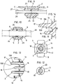
- the dowel head has a window made up of a through hole which is orthogonal to the axis of the central core and has an elongated quadrangular section, two centring tongues and one retention tongue being arranged inside said through hole, all placed transverse to said through hole, said centring tongues being located opposite one another on opposite faces of said through hole and said retention tongue being arranged on the face of said through hole furthest away from the central core of the dowel.
- the first of said retention tabs that is the one furthest away from the dowel head, has a diameter that is smaller than the diameter of the rest of said annular retention tabs and greater than the diameter of the insertion hole.
- said first annular retention tab has its edge bevelled thereby defining a larger annular face orientated towards the dowel head and a smaller annular face orientated towards the end opposite the dowel head.
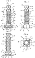
- Figures 1 to 4 show an embodiment of an improved dowel 1 according to the invention.
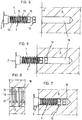
- the dowel is made up of a head 2 and a body 3 which, when the dowel is inserted into a hole 16 made beforehand in an inside wall, outside wall or facing 4, are arranged outside and inside insertion hole 16, respectively, as shown in Figure 7 .
- Head 2 is shaped like a hollow parallelepiped 5 that has its middle faces 6 open and its larger outer face 7 extends along its larger sides in two quadrangular cantilever projections 8. From the other larger inner face 9 there emerges the central core 10 of the dowel, which is joined to said larger face 9 by a short frustoparabolic connection 11.
- Central core 10 is substantially cylindrical and it is completed at its free end, opposite head 2, by at least one annular centring projection made up of a frustoconical body 12 axially aligned with said central core 10.
- a frustoconical body 12 there are two frustoconical bodies 12 and they are joined axially by a cylindrical section 21 which can be cut to adjust the length of dowel 1.
- Said frustoconical bodies 12 include bracketed tabs 22, of which there are preferably four, which are included in a virtual cylindrical space having a diameter slightly larger than that of insertion hole 16.
- annular retention tabs 13 have a larger diameter than that of annular abutment tabs 14, the diameter of the latter being equal to the diameter of insertion hole 16 in inside wall 4.
- Edge 17 of annular retention tabs 13 is bevelled through its full thickness, as illustrated in Figure 13 which shows a detail of Figure 2 , whereby there is defined a smaller face 13A orientated towards head 2 of dowel 1 and a larger face 13B orientated towards the tail of said dowel.
- edge 18 of annular abutment tabs 14 has a blunt shape, at least in the half thereof facing the annular retention tab 13 with which it forms a pair.
- the first 15 of said retention tabs 13, that is the one furthest away from dowel head 2 has a slightly different shape to the others: it has a smaller diameter, although it is larger than that of insertion hole 16, and its edge is bevelled in the opposite direction, in other words so that said first tab 15 has a larger annular face orientated towards dowel head 2 and a smaller annular face orientated towards the end opposite dowel head 2.
- annular retention tabs 13 and annular abutment 14 tabs next to head 2 of dowel 1 have two diametrically opposite partial notches 19, whereas in the rest of body 3 of dowel 1 annular retention tabs 13, 15 and annular abutment tabs 14 have complete notches 20 which reach central core 10.
- Annular retention tabs 13, and also preferably annular abutment tabs 14, as can be seen in Figure 13 and detailed in Figure 14 connect to central core 10 of body 3 of dowel 1 according to a reduced radius arc r , on their smaller face 13A orientated towards dowel head 2, while on their larger face 13B orientated towards the tail of the dowel, they connect to central core 10 according a larger radius arc R.
- Head 2 is hollow and defines a through hole 23 which opens in two windows made up of the open middle faces 6 and which is provided inside with two centring tongues 24 and a retention tongue 25, the former being intended to centre the position of a clamp 26 which is inserted into head 2 and the latter being intended to retain said clamp 26 by engaging its teeth 27.
Landscapes
- Engineering & Computer Science (AREA)
- General Engineering & Computer Science (AREA)
- Mechanical Engineering (AREA)
- Joining Of Building Structures In Genera (AREA)
- Moulds, Cores, Or Mandrels (AREA)
- Insertion Pins And Rivets (AREA)
Claims (12)
- Verbesserter Dübel (1), von der Art, die im Bauwesen, der Industrie und der Innenausstattung genutzt wird, um unter Druck in ein kreisförmiges Aufnahmeloch (16) in Innenwänden, Außenwänden, Verblendungen und ähnlichem (4) eingeführt zu werden, bestehend aus einem Stück aus synthetischem Material mit- einem Kopf (2), der an einer Stelle außerhalb des kreisförmigen Aufnahmelochs (16) verbleiben soll, wobei der Kopf (2) geeignet ist, eine Schelle (26) durch diesen hindurchzuführen und Schläge der Kraft aufzunehmen, welche aufgebracht wird, um den Dübel (1) unter Druck in das kreisförmige Aufnahmeloch (16) zu zwingen, und- einem Körper (3), der an einer Stelle innerhalb des kreisförmigen Aufnahmelochs (16) verbleiben soll, wobei der Körper (3)wobei der Durchmesser des ringförmigen Zentrierfortsatzes (12) mit dem Durchmesser des kreisförmigen Aufnahmelochs (16) zusammenfällt und der ringförmige Zentrierfortsatz (12) dazu dient, den Dübel (1) in das kreisförmige Aufnahmeloch (16) zu führen,- einen zentralen Kern (10), aus dem orthogonal eine Reihe ringförmiger Halteflügel (13) hervortritt, welche einen geringfügig größeren Durchmesser aufweisen als das kreisförmige Aufnahmeloch (16), und- wenigstens einen ringförmigen Zentrierfortsatz (12) aufweist, welcher an dem Ende des Körper (3) angeordnet ist, das dem Dübelkopf (2) gegenüber liegt,
wobei die ringförmigen Halteflügel (13) radiale Aussparungen (19, 20) mit größerer oder geringerer Tiefe aufweisen, welche die Steifigkeit der ringförmigen Halteflügel (13) verändern,
dadurch gekennzeichnet, dass jeder der ringförmigen Halteflügel (13) mit einem ähnlichen ringförmigen Stützflügel (14) ein Paar bildet,
wobei sich der ringförmige Stützflügel (14) bezogen auf den paarweise zugeordneten ringförmigen Halteflügel (13) näher am Dübelkopf (2) befindet und der ringförmige Stützflügel (14) einen Durchmesser hat, der kleiner als der Durchmesser des ringförmigen Halteflügels (13) und gleich dem Durchmesser des kreisförmigen Aufnahmelochs (16) ist,
wobei der Durchmesserunterschied und der Abstand zwischen jedem ringförmigen Halteflügel (13) und dem dazu paarweise angeordneten ringförmigen Stützflügel (14) derart gewählt sind, dass sich der ringförmige Halteflügel (13) verformen und an dem ringförmigen Stützflügel (14) sowie der Wand des kreisförmigen Aufnahmelochs (16) abstützen kann. - Verbesserter Dübel nach Anspruch 1, dadurch gekennzeichnet, dass die Kante (17) der ringförmigen Halteflügel (13) über ihre gesamte Dicke abgeschrägt ist, so dass sie für jeden ringförmigen Halteflügel (13) eine dem Dübelkopf (2) zugewandte kleinere Stirnfläche (13A) und eine der Spitze des Dübels zugewandte größere Stirnfläche (13B) definiert.
- Verbesserter Dübel nach Anspruch 1 oder 2, dadurch gekennzeichnet, dass wenigstens die dem paarweise zugeordneten ringförmigen Halteflügel (13) zugewandte Hälfte der Kante (18) der ringförmigen Stützflügel (14) stumpf ist.
- Verbesserter Dübel nach einem der Ansprüche 1 bis 3, dadurch gekennzeichnet, dass die an einem axialen Abschnitt des Dübelkörpers (3) neben dem Dübelkopf (2) angeordneten ringförmigen Halteflügel (13) und die ringförmigen Stützflügel (14) radiale Teil-Aussparungen (19) aufweisen, deren Böden mit gleichem Abstand vom zentralen Kern (10) beabstandet sind, während am übrigen Teil des zentralen Kerns (10) angeordnete ringförmige Halteflügel (13) und ringförmige Stützflügel (14) vollständige radiale Aussparungen (20) aufweisen, die bis zum zentralen Kern (10) reichen.
- Verbesserter Dübel nach Anspruch 4, dadurch gekennzeichnet, dass die radialen Teil-Aussparungen (19) und die vollständigen radialen Aussparungen (20) der ringförmigen Halteflügel (13) und ringförmigen Stützflügel (14) parallel zur Achse des zentralen Kerns (10) ausgerichtet sind.
- Verbesserter Dübel nach Anspruch 5, dadurch gekennzeichnet, dass jeder der ringförmigen Halteflügel (13) und ringförmigen Stützflügel (14) nur zwei radiale Aussparungen (19, 20) aufweist, welche, bezogen auf die Achse des zentralen Kerns (10), einander direkt gegenüber angeordnet sind.
- Verbesserter Dübel nach einem der Ansprüche 2 bis 6, dadurch gekennzeichnet, dass die ringförmigen Halteflügel (13) an ihrer dem Dübelkopf (2) zugewandten kleineren Stirnfläche (13A) und die ringförmigen Stützflügel (14) an ihrer in die gleiche Richtung weisenden Stirnfläche mit einem kleineren Radius (r) mit dem zentralen Kern (10) verbunden sind, während die ringförmigen Halteflügel (13) und ringförmigen Stützflügel (14) an ihrer der Spitze des Dübels zugewandten Stirnfläche (13B) mit einem Radius (R) mit dem zentralen Kern (10) verbunden sind, wobei der Radius (R) größer als der kleinere Radius (r) ist.
- Verbesserter Dübel nach einem der Ansprüche 1 bis 7, dadurch gekennzeichnet, dass der ringförmige Zentrierfortsatz (12) aus wenigstens einem kegelstumpfförmigen Körper (12) besteht, welcher an der dem Dübelkopf (2) gegenüberliegenden Spitze des Dübels als eine axiale Fortführung des zentralen Kerns (10) angeordnet ist und mittels seiner größeren Grundfläche koaxial mit dem zentralen Kern (10) verbunden ist und welcher Rippen (22) aufweist, die auf einer virtuellen Zylinderfläche angeordnet sind, die einen etwas größeren Durchmesser aufweist als die größere Grundfläche des kegelstumpfförmigen Körpers (12), deren Durchmesser gleich dem Durchmesser des kreisförmigen Aufnahmelochs (16) ist.
- Verbesserter Dübel nach Anspruch 8, dadurch gekennzeichnet, dass die Spitze des Dübelkörpers (3) zwei der genannten kegelstumpfförmigen Körper (12) aufweist, die voneinander durch einen Abschnitt (21) getrennt sind, der dazu bestimmt ist, das Abtrennen des kegelstumpfförmigen Körpers (12) zu ermöglichen, der dem gegenüber dem Kopf (2) gelegenen Ende des Dübels am nächsten ist.
- Verbesserter Dübel nach einem der Ansprüche 1 bis 9, dadurch gekennzeichnet, dass der Dübelkopf (2) ein Fenster aufweist, welches aus einem Durchgangsloch (23) besteht, das orthogonal zur Achse des zentalen Kerns (10) verläuft und einen gestreckten viereckigen Abschnitt, zwei Zentrierzungen (24) und eine Haltezunge (25) aufweist, die in dem Durchgangsloch angeordnet sind, wobei alle quer zum Durchgangsloch (23) angeordnet sind, wobei die Zentrierzungen (24) auf gegenüberliegenden Flächen des Durchgangslochs (23) einander gegenüberliegend angeordnet sind und wobei die Haltezunge (25) auf der vom zentralen Kern (10) des Dübels am weitesten entfernten Fläche des Durchgangslochs (23) angeordnet ist.
- Verbesserter Dübel nach einem der Ansprüche 1 bis 10, dadurch gekennzeichnet, dass der erste (15), also der am weitesten vom Dübelkopf (2) entfernte, der ringförmigen Halteflügel (13) einen kleineren Durchmesser aufweist, als die übrigen ringförmigen Halteflügel (13) und einen größeren Durchmesser aufweist als das Aufnahmeloch (16).
- Verbesserter Dübel nach Anspruch 11, dadurch gekennzeichnet, dass eine Kante des ersten ringförmigen Halteflügels (15) so abgeschrägt ist, dass sie eine dem Dübelkopf (2) zugewandte größere ringförmige Stirnfläche und eine kleinere ringförmige Stirnfläche definiert, welche dem Ende zugewandt ist, das dem Dübelkopf (2) gegenüberliegt.
Applications Claiming Priority (1)
| Application Number | Priority Date | Filing Date | Title |
|---|---|---|---|
| ES200501693U ES1060816Y (es) | 2005-07-22 | 2005-07-22 | Taco mejorado |
Publications (3)
| Publication Number | Publication Date |
|---|---|
| EP1746292A2 EP1746292A2 (de) | 2007-01-24 |
| EP1746292A3 EP1746292A3 (de) | 2012-01-25 |
| EP1746292B1 true EP1746292B1 (de) | 2017-01-18 |
Family
ID=35429758
Family Applications (1)
| Application Number | Title | Priority Date | Filing Date |
|---|---|---|---|
| EP06380192.2A Active EP1746292B1 (de) | 2005-07-22 | 2006-07-07 | Verbesserter Dübel |
Country Status (4)
| Country | Link |
|---|---|
| US (1) | US7510361B2 (de) |
| EP (1) | EP1746292B1 (de) |
| ES (2) | ES1060816Y (de) |
| PT (1) | PT1746292T (de) |
Families Citing this family (12)
| Publication number | Priority date | Publication date | Assignee | Title |
|---|---|---|---|---|
| US20080053007A1 (en) * | 2006-08-30 | 2008-03-06 | Gallagher Raymond G | Connector for insulating glazing units with multiple barriers for moisture vapor and gas |
| US7992900B2 (en) | 2008-05-01 | 2011-08-09 | Reliable Racing Supply, Inc. | Pole anchor and ski pole base with extending brush bristles and acircular, preferably hexagonal, section |
| US7983790B2 (en) * | 2008-12-19 | 2011-07-19 | The Boeing Company | Component repair using reverse engineering |
| US20120272486A1 (en) * | 2011-04-29 | 2012-11-01 | James Murphy | Zip Tie Nail and Screw Fasteners |
| ES2626331T3 (es) | 2013-01-08 | 2017-07-24 | Kmt Kunststoff- Und Metallteile Ag | Elemento de fijación |
| GB2576956B (en) * | 2018-09-10 | 2022-06-08 | Intelligent Fixings Ltd | Dowel fasteners |
| JP7570935B2 (ja) * | 2021-01-21 | 2024-10-22 | 大和化成工業株式会社 | クリップの取付構造 |
| ES2938573A1 (es) * | 2021-10-07 | 2023-04-12 | Cecotec Res And Development S L | Metodo de aspiracion automatizada por superficies |
| KR102378511B1 (ko) * | 2021-06-17 | 2022-03-23 | 문철식 | 전개형 슬리브, 앵커 볼트, 및 세트 앵커 |
| US12326210B2 (en) | 2022-03-24 | 2025-06-10 | Hellermanntyton Corporation | Quick attach clamp |
| US12338848B2 (en) * | 2022-06-30 | 2025-06-24 | Hellermanntyton Corporation | Anti-wobble fir tree mount |
| US20240360922A1 (en) | 2023-04-28 | 2024-10-31 | Hellermanntyton Corporation | Cable Tie Cradle Mount Fixings |
Family Cites Families (17)
| Publication number | Priority date | Publication date | Assignee | Title |
|---|---|---|---|---|
| FR1366886A (fr) * | 1963-06-04 | 1964-07-17 | Raymond A | Attache permettant le montage d'objets tels que des câbles ou des tubes sur un support |
| US3483787A (en) * | 1968-07-25 | 1969-12-16 | Robin Products Co | Reinforced plastic fastener |
| US3867864A (en) * | 1973-10-10 | 1975-02-25 | Illinois Tool Works | Anchor device |
| US3966339A (en) * | 1975-02-21 | 1976-06-29 | Borivoj Nemecek | Fasteners |
| GB2049859A (en) * | 1979-05-07 | 1980-12-31 | Upat Max Langensiepen Kg | A fixing device |
| US4728238A (en) * | 1980-06-16 | 1988-03-01 | Illinois Tool Works Inc. | Plastic drive fastener |
| US4834127A (en) * | 1986-04-17 | 1989-05-30 | The Kendall Co. | Self-fastening cane handle and cane assembly |
| US4902182A (en) * | 1988-10-06 | 1990-02-20 | Trw Inc. | Push-in fastener |
| JP2534800Y2 (ja) * | 1990-04-27 | 1997-05-07 | 大和化成工業 株式会社 | ベルトクランプ |
| GB9310609D0 (en) * | 1993-05-22 | 1993-07-07 | Moss Plastic Parts Ltd | An article including at least one projection |
| US5579694A (en) * | 1995-08-30 | 1996-12-03 | Polaroid Corporation | Printer adapted for use with silica-based print media |
| US5772551A (en) * | 1996-04-29 | 1998-06-30 | L.M. & L. Corporation | Dual flexible bite connector |
| US5921510A (en) * | 1996-11-21 | 1999-07-13 | Avery Dennison Corp. | Cable tie with christmas tree fastener |
| DE29908703U1 (de) * | 1999-05-18 | 1999-09-30 | TRW Automotive Electronics & Components GmbH & Co. KG, 78315 Radolfzell | Verbindungselement aus Kunststoff |
| US6520704B1 (en) * | 2000-07-03 | 2003-02-18 | Hanover Direct, Inc. | System for mounting an object to a support |
| US6923378B2 (en) * | 2000-12-22 | 2005-08-02 | Digimarc Id Systems | Identification card |
| US6536718B2 (en) * | 2001-01-11 | 2003-03-25 | Aparellaje Electrico, S.L. | Pressure plug for supporting electric cables |
-
2005
- 2005-07-22 ES ES200501693U patent/ES1060816Y/es not_active Expired - Fee Related
-
2006
- 2006-07-07 PT PT63801922T patent/PT1746292T/pt unknown
- 2006-07-07 ES ES06380192.2T patent/ES2620365T3/es active Active
- 2006-07-07 EP EP06380192.2A patent/EP1746292B1/de active Active
- 2006-07-13 US US11/485,423 patent/US7510361B2/en not_active Expired - Fee Related
Non-Patent Citations (1)
| Title |
|---|
| None * |
Also Published As
| Publication number | Publication date |
|---|---|
| ES1060816U (es) | 2005-11-16 |
| EP1746292A2 (de) | 2007-01-24 |
| ES2620365T3 (es) | 2017-06-28 |
| EP1746292A3 (de) | 2012-01-25 |
| PT1746292T (pt) | 2017-04-24 |
| ES1060816Y (es) | 2006-03-01 |
| US7510361B2 (en) | 2009-03-31 |
| US20070020064A1 (en) | 2007-01-25 |
Similar Documents
| Publication | Publication Date | Title |
|---|---|---|
| EP1746292B1 (de) | Verbesserter Dübel | |
| US2150080A (en) | Wall plug | |
| US7736107B2 (en) | Clipping device | |
| EP3347637B1 (de) | Pressfitting für rohre mit prüfring | |
| US20150041600A1 (en) | Wrap bracket damper assembly | |
| AU2016279332B2 (en) | Paper-made reel | |
| WO2008014250B1 (en) | Structural reinforcements | |
| USD1035914S1 (en) | Trim | |
| US3954345A (en) | Self-locking dowell pin | |
| CA2449377C (en) | Fastener assembly with centering elements for securing ceiling clip | |
| CA2561937A1 (en) | Connector between the weld wire feeder assembly and the welding gun | |
| AU2023250437A1 (en) | Surgical staple cartridge with an improved staple driver retaining feature | |
| AU2005280792A1 (en) | Pipe section provided with a socket end part | |
| US20040206850A1 (en) | Winding spool | |
| EP3269987B1 (de) | Verbindungsbefestigungselement | |
| US8192816B2 (en) | Support coil with mechanical locking device and method for its manufacture | |
| EP1872046B1 (de) | Freigabeklemme | |
| EP1214179B1 (de) | Bohrwerkzeug | |
| US20030152335A1 (en) | Sleeve for fixing optical cables | |
| US20090139602A1 (en) | Tool and Method for Splaying Strands of Wire Rope Ends | |
| US4952096A (en) | Dynamic earth anchor, and a sleeve therefor | |
| EP1589272B1 (de) | Rohrteil mit einem abgeschrägten Zapfenendenteil | |
| CN209880393U (zh) | 一种绕线机转芯组件 | |
| JP7563837B2 (ja) | ダクト | |
| JP2505915Y2 (ja) | 多孔管の継手構造 |
Legal Events
| Date | Code | Title | Description |
|---|---|---|---|
| PUAI | Public reference made under article 153(3) epc to a published international application that has entered the european phase |
Free format text: ORIGINAL CODE: 0009012 |
|
| AK | Designated contracting states |
Kind code of ref document: A2 Designated state(s): AT BE BG CH CY CZ DE DK EE ES FI FR GB GR HU IE IS IT LI LT LU LV MC NL PL PT RO SE SI SK TR |
|
| AX | Request for extension of the european patent |
Extension state: AL BA HR MK YU |
|
| PUAL | Search report despatched |
Free format text: ORIGINAL CODE: 0009013 |
|
| AK | Designated contracting states |
Kind code of ref document: A3 Designated state(s): AT BE BG CH CY CZ DE DK EE ES FI FR GB GR HU IE IS IT LI LT LU LV MC NL PL PT RO SE SI SK TR |
|
| AX | Request for extension of the european patent |
Extension state: AL BA HR MK RS |
|
| RIC1 | Information provided on ipc code assigned before grant |
Ipc: F16B 13/02 20060101AFI20111222BHEP |
|
| 17P | Request for examination filed |
Effective date: 20120723 |
|
| AKX | Designation fees paid |
Designated state(s): AT BE BG CH CY CZ DE DK EE ES FI FR GB GR HU IE IS IT LI LT LU LV MC NL PL PT RO SE SI SK TR |
|
| GRAP | Despatch of communication of intention to grant a patent |
Free format text: ORIGINAL CODE: EPIDOSNIGR1 |
|
| INTG | Intention to grant announced |
Effective date: 20161004 |
|
| STAA | Information on the status of an ep patent application or granted ep patent |
Free format text: STATUS: GRANT OF PATENT IS INTENDED |
|
| GRAS | Grant fee paid |
Free format text: ORIGINAL CODE: EPIDOSNIGR3 |
|
| GRAA | (expected) grant |
Free format text: ORIGINAL CODE: 0009210 |
|
| STAA | Information on the status of an ep patent application or granted ep patent |
Free format text: STATUS: THE PATENT HAS BEEN GRANTED |
|
| AK | Designated contracting states |
Kind code of ref document: B1 Designated state(s): AT BE BG CH CY CZ DE DK EE ES FI FR GB GR HU IE IS IT LI LT LU LV MC NL PL PT RO SE SI SK TR |
|
| REG | Reference to a national code |
Ref country code: GB Ref legal event code: FG4D |
|
| RIN1 | Information on inventor provided before grant (corrected) |
Inventor name: MOSTAZO OVIEDO, JOSE ANTONIO |
|
| REG | Reference to a national code |
Ref country code: CH Ref legal event code: EP |
|
| REG | Reference to a national code |
Ref country code: AT Ref legal event code: REF Ref document number: 863087 Country of ref document: AT Kind code of ref document: T Effective date: 20170215 |
|
| REG | Reference to a national code |
Ref country code: IE Ref legal event code: FG4D |
|
| REG | Reference to a national code |
Ref country code: DE Ref legal event code: R096 Ref document number: 602006051565 Country of ref document: DE |
|
| REG | Reference to a national code |
Ref country code: FR Ref legal event code: PLFP Year of fee payment: 12 |
|
| REG | Reference to a national code |
Ref country code: DE Ref legal event code: R081 Ref document number: 602006051565 Country of ref document: DE Owner name: UNEX APARELLAJE ELECTRICO S.L., L'HOSPITALET D, ES Free format text: FORMER OWNER: UNEX APARELLAJE ELECTRICO S.L., LCHOSPITALET DE LLOBREGAT, BARCELONA, ES Ref country code: DE Ref legal event code: R082 Ref document number: 602006051565 Country of ref document: DE Representative=s name: BOEHMERT & BOEHMERT ANWALTSPARTNERSCHAFT MBB -, DE |
|
| REG | Reference to a national code |
Ref country code: PT Ref legal event code: SC4A Ref document number: 1746292 Country of ref document: PT Date of ref document: 20170424 Kind code of ref document: T Free format text: AVAILABILITY OF NATIONAL TRANSLATION Effective date: 20170417 |
|
| REG | Reference to a national code |
Ref country code: NL Ref legal event code: MP Effective date: 20170118 |
|
| REG | Reference to a national code |
Ref country code: LT Ref legal event code: MG4D |
|
| REG | Reference to a national code |
Ref country code: AT Ref legal event code: MK05 Ref document number: 863087 Country of ref document: AT Kind code of ref document: T Effective date: 20170118 |
|
| REG | Reference to a national code |
Ref country code: ES Ref legal event code: FG2A Ref document number: 2620365 Country of ref document: ES Kind code of ref document: T3 Effective date: 20170628 |
|
| PG25 | Lapsed in a contracting state [announced via postgrant information from national office to epo] |
Ref country code: NL Free format text: LAPSE BECAUSE OF FAILURE TO SUBMIT A TRANSLATION OF THE DESCRIPTION OR TO PAY THE FEE WITHIN THE PRESCRIBED TIME-LIMIT Effective date: 20170118 |
|
| PG25 | Lapsed in a contracting state [announced via postgrant information from national office to epo] |
Ref country code: LT Free format text: LAPSE BECAUSE OF FAILURE TO SUBMIT A TRANSLATION OF THE DESCRIPTION OR TO PAY THE FEE WITHIN THE PRESCRIBED TIME-LIMIT Effective date: 20170118 Ref country code: FI Free format text: LAPSE BECAUSE OF FAILURE TO SUBMIT A TRANSLATION OF THE DESCRIPTION OR TO PAY THE FEE WITHIN THE PRESCRIBED TIME-LIMIT Effective date: 20170118 Ref country code: IS Free format text: LAPSE BECAUSE OF FAILURE TO SUBMIT A TRANSLATION OF THE DESCRIPTION OR TO PAY THE FEE WITHIN THE PRESCRIBED TIME-LIMIT Effective date: 20170518 Ref country code: GR Free format text: LAPSE BECAUSE OF FAILURE TO SUBMIT A TRANSLATION OF THE DESCRIPTION OR TO PAY THE FEE WITHIN THE PRESCRIBED TIME-LIMIT Effective date: 20170419 |
|
| PG25 | Lapsed in a contracting state [announced via postgrant information from national office to epo] |
Ref country code: LV Free format text: LAPSE BECAUSE OF FAILURE TO SUBMIT A TRANSLATION OF THE DESCRIPTION OR TO PAY THE FEE WITHIN THE PRESCRIBED TIME-LIMIT Effective date: 20170118 Ref country code: AT Free format text: LAPSE BECAUSE OF FAILURE TO SUBMIT A TRANSLATION OF THE DESCRIPTION OR TO PAY THE FEE WITHIN THE PRESCRIBED TIME-LIMIT Effective date: 20170118 Ref country code: BG Free format text: LAPSE BECAUSE OF FAILURE TO SUBMIT A TRANSLATION OF THE DESCRIPTION OR TO PAY THE FEE WITHIN THE PRESCRIBED TIME-LIMIT Effective date: 20170418 Ref country code: PL Free format text: LAPSE BECAUSE OF FAILURE TO SUBMIT A TRANSLATION OF THE DESCRIPTION OR TO PAY THE FEE WITHIN THE PRESCRIBED TIME-LIMIT Effective date: 20170118 Ref country code: SE Free format text: LAPSE BECAUSE OF FAILURE TO SUBMIT A TRANSLATION OF THE DESCRIPTION OR TO PAY THE FEE WITHIN THE PRESCRIBED TIME-LIMIT Effective date: 20170118 |
|
| REG | Reference to a national code |
Ref country code: DE Ref legal event code: R097 Ref document number: 602006051565 Country of ref document: DE |
|
| PG25 | Lapsed in a contracting state [announced via postgrant information from national office to epo] |
Ref country code: SK Free format text: LAPSE BECAUSE OF FAILURE TO SUBMIT A TRANSLATION OF THE DESCRIPTION OR TO PAY THE FEE WITHIN THE PRESCRIBED TIME-LIMIT Effective date: 20170118 Ref country code: EE Free format text: LAPSE BECAUSE OF FAILURE TO SUBMIT A TRANSLATION OF THE DESCRIPTION OR TO PAY THE FEE WITHIN THE PRESCRIBED TIME-LIMIT Effective date: 20170118 Ref country code: CZ Free format text: LAPSE BECAUSE OF FAILURE TO SUBMIT A TRANSLATION OF THE DESCRIPTION OR TO PAY THE FEE WITHIN THE PRESCRIBED TIME-LIMIT Effective date: 20170118 Ref country code: RO Free format text: LAPSE BECAUSE OF FAILURE TO SUBMIT A TRANSLATION OF THE DESCRIPTION OR TO PAY THE FEE WITHIN THE PRESCRIBED TIME-LIMIT Effective date: 20170118 |
|
| PLBE | No opposition filed within time limit |
Free format text: ORIGINAL CODE: 0009261 |
|
| STAA | Information on the status of an ep patent application or granted ep patent |
Free format text: STATUS: NO OPPOSITION FILED WITHIN TIME LIMIT |
|
| PG25 | Lapsed in a contracting state [announced via postgrant information from national office to epo] |
Ref country code: DK Free format text: LAPSE BECAUSE OF FAILURE TO SUBMIT A TRANSLATION OF THE DESCRIPTION OR TO PAY THE FEE WITHIN THE PRESCRIBED TIME-LIMIT Effective date: 20170118 |
|
| 26N | No opposition filed |
Effective date: 20171019 |
|
| PG25 | Lapsed in a contracting state [announced via postgrant information from national office to epo] |
Ref country code: SI Free format text: LAPSE BECAUSE OF FAILURE TO SUBMIT A TRANSLATION OF THE DESCRIPTION OR TO PAY THE FEE WITHIN THE PRESCRIBED TIME-LIMIT Effective date: 20170118 |
|
| REG | Reference to a national code |
Ref country code: CH Ref legal event code: PL |
|
| GBPC | Gb: european patent ceased through non-payment of renewal fee |
Effective date: 20170707 |
|
| REG | Reference to a national code |
Ref country code: IE Ref legal event code: MM4A |
|
| PG25 | Lapsed in a contracting state [announced via postgrant information from national office to epo] |
Ref country code: IE Free format text: LAPSE BECAUSE OF NON-PAYMENT OF DUE FEES Effective date: 20170707 Ref country code: CH Free format text: LAPSE BECAUSE OF NON-PAYMENT OF DUE FEES Effective date: 20170731 Ref country code: LI Free format text: LAPSE BECAUSE OF NON-PAYMENT OF DUE FEES Effective date: 20170731 Ref country code: GB Free format text: LAPSE BECAUSE OF NON-PAYMENT OF DUE FEES Effective date: 20170707 |
|
| REG | Reference to a national code |
Ref country code: BE Ref legal event code: MM Effective date: 20170731 |
|
| REG | Reference to a national code |
Ref country code: FR Ref legal event code: PLFP Year of fee payment: 13 |
|
| PG25 | Lapsed in a contracting state [announced via postgrant information from national office to epo] |
Ref country code: LU Free format text: LAPSE BECAUSE OF NON-PAYMENT OF DUE FEES Effective date: 20170707 |
|
| PG25 | Lapsed in a contracting state [announced via postgrant information from national office to epo] |
Ref country code: BE Free format text: LAPSE BECAUSE OF NON-PAYMENT OF DUE FEES Effective date: 20170731 |
|
| PG25 | Lapsed in a contracting state [announced via postgrant information from national office to epo] |
Ref country code: MC Free format text: LAPSE BECAUSE OF FAILURE TO SUBMIT A TRANSLATION OF THE DESCRIPTION OR TO PAY THE FEE WITHIN THE PRESCRIBED TIME-LIMIT Effective date: 20170118 Ref country code: HU Free format text: LAPSE BECAUSE OF FAILURE TO SUBMIT A TRANSLATION OF THE DESCRIPTION OR TO PAY THE FEE WITHIN THE PRESCRIBED TIME-LIMIT; INVALID AB INITIO Effective date: 20060707 |
|
| PG25 | Lapsed in a contracting state [announced via postgrant information from national office to epo] |
Ref country code: CY Free format text: LAPSE BECAUSE OF NON-PAYMENT OF DUE FEES Effective date: 20170118 |
|
| PGFP | Annual fee paid to national office [announced via postgrant information from national office to epo] |
Ref country code: IT Payment date: 20190719 Year of fee payment: 14 |
|
| PG25 | Lapsed in a contracting state [announced via postgrant information from national office to epo] |
Ref country code: TR Free format text: LAPSE BECAUSE OF FAILURE TO SUBMIT A TRANSLATION OF THE DESCRIPTION OR TO PAY THE FEE WITHIN THE PRESCRIBED TIME-LIMIT Effective date: 20170118 |
|
| REG | Reference to a national code |
Ref country code: DE Ref legal event code: R119 Ref document number: 602006051565 Country of ref document: DE |
|
| PG25 | Lapsed in a contracting state [announced via postgrant information from national office to epo] |
Ref country code: DE Free format text: LAPSE BECAUSE OF NON-PAYMENT OF DUE FEES Effective date: 20210202 |
|
| PG25 | Lapsed in a contracting state [announced via postgrant information from national office to epo] |
Ref country code: IT Free format text: LAPSE BECAUSE OF NON-PAYMENT OF DUE FEES Effective date: 20200707 |
|
| PGFP | Annual fee paid to national office [announced via postgrant information from national office to epo] |
Ref country code: PT Payment date: 20250623 Year of fee payment: 20 |
|
| PGFP | Annual fee paid to national office [announced via postgrant information from national office to epo] |
Ref country code: FR Payment date: 20250623 Year of fee payment: 20 |
|
| PGFP | Annual fee paid to national office [announced via postgrant information from national office to epo] |
Ref country code: ES Payment date: 20251017 Year of fee payment: 20 |