EP1746261A2 - Inner diameter variable vane actuation mechanism - Google Patents
Inner diameter variable vane actuation mechanism Download PDFInfo
- Publication number
- EP1746261A2 EP1746261A2 EP06253777A EP06253777A EP1746261A2 EP 1746261 A2 EP1746261 A2 EP 1746261A2 EP 06253777 A EP06253777 A EP 06253777A EP 06253777 A EP06253777 A EP 06253777A EP 1746261 A2 EP1746261 A2 EP 1746261A2
- Authority
- EP
- European Patent Office
- Prior art keywords
- vane
- drive
- arm
- drive vane
- fan case
- Prior art date
- Legal status (The legal status is an assumption and is not a legal conclusion. Google has not performed a legal analysis and makes no representation as to the accuracy of the status listed.)
- Granted
Links
Images
Classifications
-
- F—MECHANICAL ENGINEERING; LIGHTING; HEATING; WEAPONS; BLASTING
- F04—POSITIVE - DISPLACEMENT MACHINES FOR LIQUIDS; PUMPS FOR LIQUIDS OR ELASTIC FLUIDS
- F04D—NON-POSITIVE-DISPLACEMENT PUMPS
- F04D27/00—Control, e.g. regulation, of pumps, pumping installations or pumping systems specially adapted for elastic fluids
- F04D27/02—Surge control
- F04D27/0246—Surge control by varying geometry within the pumps, e.g. by adjusting vanes
-
- F—MECHANICAL ENGINEERING; LIGHTING; HEATING; WEAPONS; BLASTING
- F01—MACHINES OR ENGINES IN GENERAL; ENGINE PLANTS IN GENERAL; STEAM ENGINES
- F01D—NON-POSITIVE DISPLACEMENT MACHINES OR ENGINES, e.g. STEAM TURBINES
- F01D17/00—Regulating or controlling by varying flow
- F01D17/10—Final actuators
- F01D17/12—Final actuators arranged in stator parts
- F01D17/14—Final actuators arranged in stator parts varying effective cross-sectional area of nozzles or guide conduits
- F01D17/16—Final actuators arranged in stator parts varying effective cross-sectional area of nozzles or guide conduits by means of nozzle vanes
- F01D17/162—Final actuators arranged in stator parts varying effective cross-sectional area of nozzles or guide conduits by means of nozzle vanes for axial flow, i.e. the vanes turning around axes which are essentially perpendicular to the rotor centre line
-
- F—MECHANICAL ENGINEERING; LIGHTING; HEATING; WEAPONS; BLASTING
- F04—POSITIVE - DISPLACEMENT MACHINES FOR LIQUIDS; PUMPS FOR LIQUIDS OR ELASTIC FLUIDS
- F04D—NON-POSITIVE-DISPLACEMENT PUMPS
- F04D29/00—Details, component parts, or accessories
- F04D29/40—Casings; Connections of working fluid
- F04D29/52—Casings; Connections of working fluid for axial pumps
- F04D29/54—Fluid-guiding means, e.g. diffusers
- F04D29/56—Fluid-guiding means, e.g. diffusers adjustable
- F04D29/563—Fluid-guiding means, e.g. diffusers adjustable specially adapted for elastic fluid pumps
-
- F—MECHANICAL ENGINEERING; LIGHTING; HEATING; WEAPONS; BLASTING
- F02—COMBUSTION ENGINES; HOT-GAS OR COMBUSTION-PRODUCT ENGINE PLANTS
- F02B—INTERNAL-COMBUSTION PISTON ENGINES; COMBUSTION ENGINES IN GENERAL
- F02B37/00—Engines characterised by provision of pumps driven at least for part of the time by exhaust
- F02B37/12—Control of the pumps
- F02B37/24—Control of the pumps by using pumps or turbines with adjustable guide vanes
-
- F—MECHANICAL ENGINEERING; LIGHTING; HEATING; WEAPONS; BLASTING
- F05—INDEXING SCHEMES RELATING TO ENGINES OR PUMPS IN VARIOUS SUBCLASSES OF CLASSES F01-F04
- F05D—INDEXING SCHEME FOR ASPECTS RELATING TO NON-POSITIVE-DISPLACEMENT MACHINES OR ENGINES, GAS-TURBINES OR JET-PROPULSION PLANTS
- F05D2230/00—Manufacture
- F05D2230/60—Assembly methods
- F05D2230/64—Assembly methods using positioning or alignment devices for aligning or centring, e.g. pins
- F05D2230/642—Assembly methods using positioning or alignment devices for aligning or centring, e.g. pins using maintaining alignment while permitting differential dilatation
Definitions
- This invention relates generally to gas turbine engines and more particularly to variable stator vane assemblies for use in such engines.
- Gas turbine engines operate by combusting a fuel source in compressed air to create heated gases with increased pressure and density.
- the heated gases are ultimately forced through an exhaust nozzle, which is used to step up the velocity of the exiting gases and in-turn produce thrust for driving an aircraft.
- the heated air is also used to drive a turbine for rotating a fan to provide air to a compressor section of the gas turbine engine. Additionally, the heated gases are used for driving rotor blades inside the compressor section, which provides the compressed air used during combustion.
- the compressor section of a gas turbine engine typically comprises a series of rotor blade and stator vane stages. At each stage, rotating blades push air past the stationary vanes. Each rotor/stator stage increases the pressure and density of the air. Stators serve two purposes: they convert the kinetic energy of the air into pressure, and they redirect the trajectory of the air coming off the rotors for flow into the next compressor stage.
- the speed range of an aircraft powered by a gas turbine engine is directly related to the level of air pressure generated in the compressor section. For different aircraft speeds, the velocity of the airflow through the gas turbine engine varies. Thus, the incidence of the air onto rotor blades of subsequent compressor stages differs at different aircraft speeds.
- One way of achieving more efficient performance of the gas turbine engine over the entire speed range, especially at high speed/high pressure ranges, is to use variable stator vanes which can optimize the incidence of the airflow onto subsequent compressor stage rotors.
- Variable stator vanes are typically circumferentially arranged between an outer diameter fan case and an inner diameter vane shroud.
- a synchronizing mechanism simultaneously rotates the individual stator vanes in response to an external actuation source.
- the compressor section In some situations, it is advantageous to divide the compressor section into upper and lower halves to expedite maintenance of the gas turbine engine. It is particularly advantageous, for example, in military applications when maintenance must be performed in remote locations where complete disassembly is imprudent.
- the synchronizing mechanism In dividing the compressor section into halves, the synchronizing mechanism must also be split apart. This creates two synchronizing mechanisms that must be actuated in unison to orchestrate simultaneous operation of all of the stator vanes. Synchronizing mechanisms that are located on the outer case can be accessed and spliced together easily. However, this is not the case for inner diameter synchronizing mechanisms, which cannot be accessed after assembly to attach the synchronizing mechanisms together. Thus, there is a need for an apparatus for coordinating actuation of split inner diameter synchronizing mechanisms.
- the present invention comprises a first drive vane arm and a second drive vane arm for driving a first variable vane array and a second variable vane array, respectively, of a stator vane section of a gas turbine engine.
- the first drive vane arm and second drive vane arm are connected to each other at a first end by a linkage.
- the first drive vane arm and second drive vane arm are connected at a second end to a first drive vane and a second drive vane, respectively, of the first and second variable vane arrays.
- the first drive vane arm and second drive vane arm respond in unison to a single actuation source connected to one of the first drive vane arm and second drive vane arm.
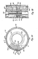
- FIG. 1A shows a back view of stator vane section 10 of a gas turbine engine in which the present invention is used.
- Stator vane section 10 comprises fan case 12, vane shroud 14, variable stator vane array 16 and actuator 18.
- Stator vane array 16 is comprised of drive vanes 20A and 20B and follower vanes 22A and 22B.
- follower vanes 22 encircle the entirety of vane shroud 14.
- Drive vanes 20 and follower vanes rotate about their axis in fan case 12 and inner diameter vane shroud 14.
- Drive vanes 20A and 20B are connected directly with actuator 18 at their outer diameter end.
- Drive vanes 20A and 20B are connected inside vane shroud 14 by a variable vane synchronizing mechanism such that when actuator 18 rotates drive vanes 20, follower vanes 22 rotate a like amount.
- Stator vane section 10 is divided into first and second subassemblies.
- Fan case 12 is comprised of a first fan case component 24A and second fan case component 24B.
- Vane shroud 14 is similarly comprised of first vane shroud component 26A and second vane shroud component 26B.
- Stator vane array 16 is also comprised of a first array component 28A and second array component 28B component.
- the fan case components, the vane shroud components and the vane array components comprise upper and lower assemblies for use in a split fan configuration.
- the first and second subassemblies come together at first split line 30A and second split line 30B.
- First array component 28A and second array component 28B operate independently from one another.
- the synchronizing mechanism contained within vane shroud 14 does not synchronize the rotation of the first array component 28A and second array component 28B because of the discontinuity caused by first split line 30A and second split line 30B.
- FIG. 1B shows a side view of stator vane section 10 of a gas turbine engine in which the present invention is used.
- First fan case component 24A and second fan case component 24B come together at split line 30A.
- First fan case component 24A includes first array component 28A.
- Second fan case portion 24B includes second vane array 28B.
- First array component 28A and second array component 28B are independently synchronized with respective internal synchronizing mechanisms.
- Actuator 18 drives first array component 28A and second array component 28B with arm assembly 34.
- Arm assembly 34 includes linkage 36, which connects both first array component 28A and second array component 28B to actuator 18.
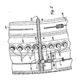
- FIG. 2 shows a close up perspective view of arm assembly 34 shown in FIG. 1B.
- Arm assembly 34 comprises linkage 36, first arm 38A and second arm 38B.
- Linkage 36 can be disconnected from first arm 38A and or second arm 38B for uncoupling of first fan case 24A and second fan case 24B.
- First fan case portion 24A and second fan case portion 24B come together at seam line 30A.
- First variable stator vane array 28A includes first stator vanes 22A that pivot within first fan case portion 24A at their outer diameter end.
- First stator vanes 22A are connected inside first vane shroud 24A by a synchronizing mechanism such that they all rotate in unison when any individual vane (e.g. drive vane 20A) is rotated.
- Second variable stator vane array 28B includes second stator vanes 22B that pivot within second fan case portion 24B at their outer diameter end.
- Second stator vanes 22B are connected inside second vane shroud 24B by a synchronizing mechanism such that they all rotate in unison when any individual vane (e.g. drive vane 20B) is rotated.
- First variable stator vane array 28A and second variable stator vane array 28B operate independently of each other.
- Actuator 18 is connected to a drive mechanism (not shown) that causes up and down motion (as shown in FIG. 2) of actuator 18.
- Second variable stator vane array 28B is connected to actuator 18 with second arm 38B.
- drive vane 20B is rotated correspondingly.
- drive vane 20B is selected to be next to or near split line 30A.
- Second arm 38B provides a moment arm for rotating stator vane 20B.
- second follower vanes 22B are also rotated by the synchronizing mechanism inside second vane shroud 26B.
- First variable stator vane array 28A is connected to first arm 38A through drive vane 20A.
- First arm 38A is connected to second arm 38B by linkage 36.
- linkage 36 rotates first arm 38A.
- First arm 38A provides a moment arm for rotating drive vane 20A.
- drive vane 20A is selected to be next to or near split line 30A.
- follower vanes 22A also rotated by the synchronizing mechanism inside second vane shroud 26A.
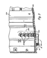
- FIG. 3 shows a top view of arm assembly 34 of the present invention.
- First arm 38A is connected to the outer diameter end of drive vane 20A.
- First arm 38A is approximately parallel to first fan case portion 24A and approximately in the same plane as second arm 38B.
- the specific size and location of first arm 38A and lower arm 38B are dictated by the location of other external components of the gas turbine engine, including the drive mechanism of actuator 18, and the specific actuation requirements of the particular variable vane arrays.
Abstract
Description
- This invention relates generally to gas turbine engines and more particularly to variable stator vane assemblies for use in such engines.
- Gas turbine engines operate by combusting a fuel source in compressed air to create heated gases with increased pressure and density. The heated gases are ultimately forced through an exhaust nozzle, which is used to step up the velocity of the exiting gases and in-turn produce thrust for driving an aircraft. The heated air is also used to drive a turbine for rotating a fan to provide air to a compressor section of the gas turbine engine. Additionally, the heated gases are used for driving rotor blades inside the compressor section, which provides the compressed air used during combustion. The compressor section of a gas turbine engine typically comprises a series of rotor blade and stator vane stages. At each stage, rotating blades push air past the stationary vanes. Each rotor/stator stage increases the pressure and density of the air. Stators serve two purposes: they convert the kinetic energy of the air into pressure, and they redirect the trajectory of the air coming off the rotors for flow into the next compressor stage.
- The speed range of an aircraft powered by a gas turbine engine is directly related to the level of air pressure generated in the compressor section. For different aircraft speeds, the velocity of the airflow through the gas turbine engine varies. Thus, the incidence of the air onto rotor blades of subsequent compressor stages differs at different aircraft speeds. One way of achieving more efficient performance of the gas turbine engine over the entire speed range, especially at high speed/high pressure ranges, is to use variable stator vanes which can optimize the incidence of the airflow onto subsequent compressor stage rotors.
- Variable stator vanes are typically circumferentially arranged between an outer diameter fan case and an inner diameter vane shroud. A synchronizing mechanism simultaneously rotates the individual stator vanes in response to an external actuation source.
- In some situations, it is advantageous to divide the compressor section into upper and lower halves to expedite maintenance of the gas turbine engine. It is particularly advantageous, for example, in military applications when maintenance must be performed in remote locations where complete disassembly is imprudent. However, in dividing the compressor section into halves, the synchronizing mechanism must also be split apart. This creates two synchronizing mechanisms that must be actuated in unison to orchestrate simultaneous operation of all of the stator vanes. Synchronizing mechanisms that are located on the outer case can be accessed and spliced together easily. However, this is not the case for inner diameter synchronizing mechanisms, which cannot be accessed after assembly to attach the synchronizing mechanisms together. Thus, there is a need for an apparatus for coordinating actuation of split inner diameter synchronizing mechanisms.
- The present invention comprises a first drive vane arm and a second drive vane arm for driving a first variable vane array and a second variable vane array, respectively, of a stator vane section of a gas turbine engine. The first drive vane arm and second drive vane arm are connected to each other at a first end by a linkage. The first drive vane arm and second drive vane arm are connected at a second end to a first drive vane and a second drive vane, respectively, of the first and second variable vane arrays. The first drive vane arm and second drive vane arm respond in unison to a single actuation source connected to one of the first drive vane arm and second drive vane arm.
-
- FIG. 1A shows a back view of a stator vane section of a gas turbine engine in which the present invention is used.
- FIG. 1B shows a side view of a stator vane section of a gas turbine engine in which the present invention is used.
- FIG. 2 shows a close up perspective view of the actuation mechanism of the present invention shown in FIG. 1B.
- FIG. 3 shows a top view of the actuation mechanism of the present invention.
- FIG. 1A shows a back view of
stator vane section 10 of a gas turbine engine in which the present invention is used.Stator vane section 10 comprisesfan case 12, vane shroud 14, variablestator vane array 16 andactuator 18.Stator vane array 16 is comprised ofdrive vanes follower vanes stator vane array 16 is shown. Drive vanes 20 and follower vanes rotate about their axis infan case 12 and inner diameter vane shroud 14.Drive vanes actuator 18 at their outer diameter end.Drive vanes actuator 18 rotates drive vanes 20, follower vanes 22 rotate a like amount. -
Stator vane section 10 is divided into first and second subassemblies.Fan case 12 is comprised of a firstfan case component 24A and secondfan case component 24B. Vane shroud 14 is similarly comprised of firstvane shroud component 26A and secondvane shroud component 26B.Stator vane array 16 is also comprised of afirst array component 28A andsecond array component 28B component. In one embodiment, the fan case components, the vane shroud components and the vane array components comprise upper and lower assemblies for use in a split fan configuration. The first and second subassemblies come together atfirst split line 30A andsecond split line 30B.First array component 28A andsecond array component 28B operate independently from one another. The synchronizing mechanism contained within vane shroud 14 does not synchronize the rotation of thefirst array component 28A andsecond array component 28B because of the discontinuity caused byfirst split line 30A andsecond split line 30B. - FIG. 1B shows a side view of
stator vane section 10 of a gas turbine engine in which the present invention is used. Firstfan case component 24A and secondfan case component 24B come together atsplit line 30A. Firstfan case component 24A includesfirst array component 28A. Secondfan case portion 24B includessecond vane array 28B.First array component 28A andsecond array component 28B are independently synchronized with respective internal synchronizing mechanisms. Actuator 18 drivesfirst array component 28A andsecond array component 28B witharm assembly 34.Arm assembly 34 includeslinkage 36, which connects bothfirst array component 28A andsecond array component 28B toactuator 18. - FIG. 2 shows a close up perspective view of
arm assembly 34 shown in FIG. 1B.Arm assembly 34 compriseslinkage 36,first arm 38A andsecond arm 38B.Linkage 36 can be disconnected fromfirst arm 38A and orsecond arm 38B for uncoupling offirst fan case 24A andsecond fan case 24B. Firstfan case portion 24A and secondfan case portion 24B come together atseam line 30A. - First variable
stator vane array 28A includesfirst stator vanes 22A that pivot within firstfan case portion 24A at their outer diameter end.First stator vanes 22A are connected insidefirst vane shroud 24A by a synchronizing mechanism such that they all rotate in unison when any individual vane (e.g. drivevane 20A) is rotated. Second variablestator vane array 28B includessecond stator vanes 22B that pivot within secondfan case portion 24B at their outer diameter end.Second stator vanes 22B are connected insidesecond vane shroud 24B by a synchronizing mechanism such that they all rotate in unison when any individual vane (e.g. drivevane 20B) is rotated. First variablestator vane array 28A and second variablestator vane array 28B operate independently of each other. -
Actuator 18 is connected to a drive mechanism (not shown) that causes up and down motion (as shown in FIG. 2) ofactuator 18. Second variablestator vane array 28B is connected to actuator 18 withsecond arm 38B. Asactuator 18 is moved up or down by the drive mechanism,drive vane 20B is rotated correspondingly. Preferably,drive vane 20B is selected to be next to or nearsplit line 30A.Second arm 38B provides a moment arm for rotatingstator vane 20B. As a result ofdrive vane 20B being rotated,second follower vanes 22B are also rotated by the synchronizing mechanism insidesecond vane shroud 26B. - First variable
stator vane array 28A is connected tofirst arm 38A throughdrive vane 20A.First arm 38A is connected tosecond arm 38B bylinkage 36. Assecond arm 38B is rotated byactuator 18,linkage 36 rotatesfirst arm 38A.First arm 38A provides a moment arm for rotatingdrive vane 20A. Preferably, drivevane 20A is selected to be next to or nearsplit line 30A. As a result ofdrive vane 20A being rotated,follower vanes 22A also rotated by the synchronizing mechanism insidesecond vane shroud 26A. Thus, a single actuator,actuator 18, drives both first variablestator vane array 28A and second variablestator vane array 28B. - FIG. 3 shows a top view of
arm assembly 34 of the present invention.First arm 38A is connected to the outer diameter end ofdrive vane 20A.First arm 38A is approximately parallel to firstfan case portion 24A and approximately in the same plane assecond arm 38B. The specific size and location offirst arm 38A andlower arm 38B are dictated by the location of other external components of the gas turbine engine, including the drive mechanism ofactuator 18, and the specific actuation requirements of the particular variable vane arrays. - Although the present invention has been described with reference to preferred embodiments, workers skilled in the art will recognize that changes may be made in form and detail without departing from the scope of the invention.
Claims (8)
- A variable stator vane actuation system for use in a turbine engine having a first fan case (24A) having a first array of variable vanes (20A,22A) and a second fan case (24B) having a second array of variable vanes, the actuation system comprising:a first drive vane arm (38A) for supplying a rotational force to a first drive vane (20A) of the first array of variable vanes;a second drive vane arm (38B) for supplying a rotational force to a second drive vane (20B) of the second array of variable vanes; anda linkage (36) for connecting the first drive vane arm (38A) and the second drive vane arm (38B) to coordinate rotation of the first and second arrays of variable vanes.
- The actuation system of claim 1 wherein the first drive vane arm (38A) and the second drive vane arm (38B) comprise:a first end adapted for connection to an outer diameter end of a variable vane (20A,20B);a second end adapted for connection to the linkage (36) and an actuation source (18).
- A variable vane assembly for use in a turbine engine, the stator vane section (10) comprising:a first assembly comprising:a first fan case (24A);a first inner diameter vane shroud (26A);a first drive vane (20A) rotatably positioned between the first fan case and the first inner diameter vane shroud;a first array of follower vanes (22A) rotatably positioned between the first fan case and the first inner diameter vane shroud; anda first drive vane arm (38A) for rotating the first drive vane; anda second assembly comprising:a second fan case (24B);a second inner diameter vane shroud (26B);a second drive vane (20B) rotatably positioned between the second fan case and the second inner diameter vane shroud;a second array of follower vanes (22B) rotatably positioned between the second fan case and the second inner diameter vane shroud; anda second drive vane arm (38B) for rotating the second drive vane;an actuator (18); anda linkage (36) for connecting the first drive vane arm (38A) and the second drive vane arm (38B) such that when one drive vane arm is rotated an amount by the actuator, the other drive vane arm is rotated a like amount, thereby coordinating the rotation of both the first and second variable vane arrays.
- The stator vane section of claim 3 wherein the first drive vane arm (38A) and the second drive vane arm (38B) comprise:a first end adapted for connection to a drive vane (20A,20B);a second end adapted for connection to the linkage (36) and the actuator (18).
- The actuation system or stator vane section of any preceding claim wherein the first fan case (24A) and second fan case (24B) are joined at split lines (30A,30B).
- The actuation system or stator vane section of claim 5 wherein the first drive vane (20A) is located next to a split line (30A) of the first fan case (24A).
- The actuation system or stator vane section of claim 5 or 6 wherein the second drive vane (20B) is located next to a split line (30A) of the second fan case (24B).
- The actuation system or stator vane section of any preceding claim wherein the linkage (36) is removable from the first drive vane arm (38A) and the second drive vane arm (38B).
Priority Applications (1)
| Application Number | Priority Date | Filing Date | Title |
|---|---|---|---|
| EP12179422.6A EP2522815B1 (en) | 2005-07-20 | 2006-07-19 | Inner diameter variable vane actuation mechanism |
Applications Claiming Priority (1)
| Application Number | Priority Date | Filing Date | Title |
|---|---|---|---|
| US11/185,995 US7690889B2 (en) | 2005-07-20 | 2005-07-20 | Inner diameter variable vane actuation mechanism |
Related Child Applications (2)
| Application Number | Title | Priority Date | Filing Date |
|---|---|---|---|
| EP12179422.6A Division EP2522815B1 (en) | 2005-07-20 | 2006-07-19 | Inner diameter variable vane actuation mechanism |
| EP12179422.6 Division-Into | 2012-08-06 |
Publications (3)
| Publication Number | Publication Date |
|---|---|
| EP1746261A2 true EP1746261A2 (en) | 2007-01-24 |
| EP1746261A3 EP1746261A3 (en) | 2010-04-21 |
| EP1746261B1 EP1746261B1 (en) | 2013-01-02 |
Family
ID=37395851
Family Applications (2)
| Application Number | Title | Priority Date | Filing Date |
|---|---|---|---|
| EP12179422.6A Active EP2522815B1 (en) | 2005-07-20 | 2006-07-19 | Inner diameter variable vane actuation mechanism |
| EP06253777A Active EP1746261B1 (en) | 2005-07-20 | 2006-07-19 | Inner diameter variable vane actuation mechanism |
Family Applications Before (1)
| Application Number | Title | Priority Date | Filing Date |
|---|---|---|---|
| EP12179422.6A Active EP2522815B1 (en) | 2005-07-20 | 2006-07-19 | Inner diameter variable vane actuation mechanism |
Country Status (6)
| Country | Link |
|---|---|
| US (1) | US7690889B2 (en) |
| EP (2) | EP2522815B1 (en) |
| JP (1) | JP2007024050A (en) |
| CN (1) | CN1900489A (en) |
| CA (1) | CA2552655A1 (en) |
| IL (1) | IL176951A0 (en) |
Cited By (1)
| Publication number | Priority date | Publication date | Assignee | Title |
|---|---|---|---|---|
| WO2013087863A1 (en) * | 2011-12-16 | 2013-06-20 | Siemens Aktiengesellschaft | Turbomachine and method for the operation thereof |
Families Citing this family (27)
| Publication number | Priority date | Publication date | Assignee | Title |
|---|---|---|---|---|
| US7588415B2 (en) * | 2005-07-20 | 2009-09-15 | United Technologies Corporation | Synch ring variable vane synchronizing mechanism for inner diameter vane shroud |
| US8007229B2 (en) * | 2007-05-24 | 2011-08-30 | United Technologies Corporation | Variable area turbine vane arrangement |
| US8794923B2 (en) | 2010-10-29 | 2014-08-05 | United Technologies Corporation | Gas turbine engine rotor tie shaft arrangement |
| US20120134783A1 (en) | 2010-11-30 | 2012-05-31 | General Electric Company | System and method for operating a compressor |
| US9033654B2 (en) * | 2010-12-30 | 2015-05-19 | Rolls-Royce Corporation | Variable geometry vane system for gas turbine engines |
| US8794910B2 (en) | 2011-02-01 | 2014-08-05 | United Technologies Corporation | Gas turbine engine synchronizing ring bumper |
| US8909454B2 (en) * | 2011-04-08 | 2014-12-09 | General Electric Company | Control of compression system with independently actuated inlet guide and/or stator vanes |
| US8915703B2 (en) * | 2011-07-28 | 2014-12-23 | United Technologies Corporation | Internally actuated inlet guide vane for fan section |
| US20140064912A1 (en) * | 2012-08-29 | 2014-03-06 | General Electric Company | Systems and Methods to Control Variable Stator Vanes in Gas Turbine Engines |
| US9528376B2 (en) | 2012-09-13 | 2016-12-27 | General Electric Company | Compressor fairing segment |
| WO2015026597A1 (en) * | 2013-08-21 | 2015-02-26 | United Technologies Corporation | Variable area turbine arrangement with secondary flow modulation |
| DE102014223975A1 (en) * | 2014-11-25 | 2016-05-25 | MTU Aero Engines AG | Guide vane ring and turbomachine |
| US11391298B2 (en) * | 2015-10-07 | 2022-07-19 | General Electric Company | Engine having variable pitch outlet guide vanes |
| US10107130B2 (en) * | 2016-03-24 | 2018-10-23 | United Technologies Corporation | Concentric shafts for remote independent variable vane actuation |
| US10458271B2 (en) | 2016-03-24 | 2019-10-29 | United Technologies Corporation | Cable drive system for variable vane operation |
| US10415596B2 (en) | 2016-03-24 | 2019-09-17 | United Technologies Corporation | Electric actuation for variable vanes |
| US10329947B2 (en) | 2016-03-24 | 2019-06-25 | United Technologies Corporation | 35Geared unison ring for multi-stage variable vane actuation |
| US10301962B2 (en) | 2016-03-24 | 2019-05-28 | United Technologies Corporation | Harmonic drive for shaft driving multiple stages of vanes via gears |
| US10288087B2 (en) | 2016-03-24 | 2019-05-14 | United Technologies Corporation | Off-axis electric actuation for variable vanes |
| US10190599B2 (en) | 2016-03-24 | 2019-01-29 | United Technologies Corporation | Drive shaft for remote variable vane actuation |
| US10294813B2 (en) * | 2016-03-24 | 2019-05-21 | United Technologies Corporation | Geared unison ring for variable vane actuation |
| US10443430B2 (en) | 2016-03-24 | 2019-10-15 | United Technologies Corporation | Variable vane actuation with rotating ring and sliding links |
| US10443431B2 (en) * | 2016-03-24 | 2019-10-15 | United Technologies Corporation | Idler gear connection for multi-stage variable vane actuation |
| US10329946B2 (en) | 2016-03-24 | 2019-06-25 | United Technologies Corporation | Sliding gear actuation for variable vanes |
| US10563670B2 (en) | 2016-07-29 | 2020-02-18 | Rolls-Royce Corporation | Vane actuation system for a gas turbine engine |
| GB201614803D0 (en) * | 2016-09-01 | 2016-10-19 | Rolls Royce Plc | Variable stator vane rigging |
| DE102017209682A1 (en) | 2017-06-08 | 2018-12-13 | MTU Aero Engines AG | Axially split turbomachinery inner ring |
Citations (3)
| Publication number | Priority date | Publication date | Assignee | Title |
|---|---|---|---|---|
| US5259187A (en) * | 1993-02-05 | 1993-11-09 | General Electric Company | Method of operating an aircraft bypass turbofan engine having variable fan outlet guide vanes |
| GB2290062A (en) * | 1994-06-06 | 1995-12-13 | Rolls Royce Plc | Mechanism for operating a cascade of variable pitch thrust vectoring vanes |
| EP0909880A2 (en) * | 1997-10-14 | 1999-04-21 | General Electric Company | Turbine vane actuation system |
Family Cites Families (33)
| Publication number | Priority date | Publication date | Assignee | Title |
|---|---|---|---|---|
| US2233983A (en) * | 1938-07-22 | 1941-03-04 | American Blower Corp | High-speed inlet vane |
| US2805818A (en) * | 1951-12-13 | 1957-09-10 | Ferri Antonio | Stator for axial flow compressor with supersonic velocity at entrance |
| GB737473A (en) * | 1952-10-03 | 1955-09-28 | Napier & Son Ltd | Turbines and like machines having adjustable guide blades |
| US2933234A (en) * | 1954-12-28 | 1960-04-19 | Gen Electric | Compressor stator assembly |
| US2994509A (en) * | 1959-04-10 | 1961-08-01 | Curtiss Wright Corp | Variable area turbine nozzle |
| US3025036A (en) * | 1960-01-06 | 1962-03-13 | Curtiss Wright Corp | Gas turbine speed control |
| GB936504A (en) * | 1961-02-22 | 1963-09-11 | Rolls Royce | Improvements in compressor intakes for gas turbine engines |
| US3314654A (en) * | 1965-07-30 | 1967-04-18 | Gen Electric | Variable area turbine nozzle for axial flow gas turbine engines |
| GB1067930A (en) * | 1965-12-29 | 1967-05-10 | Rolls Royce | Vane operating mechanism for fluid flow machines |
| US3632224A (en) * | 1970-03-02 | 1972-01-04 | Gen Electric | Adjustable-blade turbine |
| US3836327A (en) * | 1971-01-08 | 1974-09-17 | Sybron Corp | Aromatic alcohol-aromatic aldehyde carrier dyeing of aromatic polyamides |
| US3685920A (en) * | 1971-02-01 | 1972-08-22 | Gen Electric | Actuation ring for variable geometry compressors or gas turbine engines |
| GB1400718A (en) * | 1971-12-11 | 1975-07-23 | Lucas Industries Ltd | Control vane arrangement for a turbine |
| US4044815A (en) | 1976-11-01 | 1977-08-30 | General Electric Company | Precision investment casting mold, pattern assembly and method |
| GB2206381B (en) * | 1987-06-30 | 1991-10-09 | Rolls Royce Plc | A variable stator vane arrangement for a compressor |
| US4792277A (en) * | 1987-07-08 | 1988-12-20 | United Technologies Corporation | Split shroud compressor |
| US4834613A (en) | 1988-02-26 | 1989-05-30 | United Technologies Corporation | Radially constrained variable vane shroud |
| FR2646467A1 (en) | 1989-04-26 | 1990-11-02 | Snecma | STATOR VARIABLE STATOR VANE WITH REPLACED CUP |
| GB8913988D0 (en) | 1989-06-17 | 1989-08-09 | Rolls Royce Plc | Improvements in or relating to control of variable stator vanes |
| US4990056A (en) * | 1989-11-16 | 1991-02-05 | General Motors Corporation | Stator vane stage in axial flow compressor |
| FR2685033B1 (en) * | 1991-12-11 | 1994-02-11 | Snecma | STATOR DIRECTING THE AIR INLET INSIDE A TURBOMACHINE AND METHOD FOR MOUNTING A VANE OF THIS STATOR. |
| DE4237031C1 (en) * | 1992-11-03 | 1994-02-10 | Mtu Muenchen Gmbh | Adjustable guide vane |
| FR2699595B1 (en) * | 1992-12-23 | 1995-01-20 | Snecma | Device for guiding in rotation a control ring for pivoting vanes. |
| GB9511269D0 (en) * | 1995-06-05 | 1995-08-02 | Rolls Royce Plc | Variable angle vane arrays |
| US5601401A (en) * | 1995-12-21 | 1997-02-11 | United Technologies Corporation | Variable stage vane actuating apparatus |
| US6321449B2 (en) | 1998-11-12 | 2001-11-27 | General Electric Company | Method of forming hollow channels within a component |
| US6283705B1 (en) | 1999-02-26 | 2001-09-04 | Allison Advanced Development Company | Variable vane with winglet |
| FR2814206B1 (en) * | 2000-09-18 | 2002-12-20 | Snecma Moteurs | VARIABLE SETTING BLADE CONTROL DEVICE |
| US6413043B1 (en) | 2000-11-09 | 2002-07-02 | General Electric Company | Inlet guide vane and shroud support contact |
| DE10161292A1 (en) * | 2001-12-13 | 2003-06-26 | Rolls Royce Deutschland | Bearing ring for the storage of blade roots of adjustable stator blades in the high pressure compressor of a gas turbine |
| FR2835562B1 (en) * | 2002-02-07 | 2004-07-16 | Snecma Moteurs | STATOR BLADE SWIVEL ARRANGEMENT IN A TURBOMACHINE |
| US6843638B2 (en) | 2002-12-10 | 2005-01-18 | Honeywell International Inc. | Vane radial mounting apparatus |
| GB2402179B (en) * | 2003-05-27 | 2006-02-22 | Rolls Royce Plc | A variable vane arrangement for a turbomachine |
-
2005
- 2005-07-20 US US11/185,995 patent/US7690889B2/en not_active Expired - Fee Related
-
2006
- 2006-07-18 CA CA002552655A patent/CA2552655A1/en not_active Abandoned
- 2006-07-19 EP EP12179422.6A patent/EP2522815B1/en active Active
- 2006-07-19 JP JP2006196391A patent/JP2007024050A/en active Pending
- 2006-07-19 IL IL176951A patent/IL176951A0/en unknown
- 2006-07-19 EP EP06253777A patent/EP1746261B1/en active Active
- 2006-07-20 CN CNA2006101214037A patent/CN1900489A/en active Pending
Patent Citations (3)
| Publication number | Priority date | Publication date | Assignee | Title |
|---|---|---|---|---|
| US5259187A (en) * | 1993-02-05 | 1993-11-09 | General Electric Company | Method of operating an aircraft bypass turbofan engine having variable fan outlet guide vanes |
| GB2290062A (en) * | 1994-06-06 | 1995-12-13 | Rolls Royce Plc | Mechanism for operating a cascade of variable pitch thrust vectoring vanes |
| EP0909880A2 (en) * | 1997-10-14 | 1999-04-21 | General Electric Company | Turbine vane actuation system |
Cited By (1)
| Publication number | Priority date | Publication date | Assignee | Title |
|---|---|---|---|---|
| WO2013087863A1 (en) * | 2011-12-16 | 2013-06-20 | Siemens Aktiengesellschaft | Turbomachine and method for the operation thereof |
Also Published As
| Publication number | Publication date |
|---|---|
| CA2552655A1 (en) | 2007-01-20 |
| US20070020094A1 (en) | 2007-01-25 |
| EP1746261A3 (en) | 2010-04-21 |
| CN1900489A (en) | 2007-01-24 |
| EP2522815A1 (en) | 2012-11-14 |
| EP2522815B1 (en) | 2014-08-20 |
| JP2007024050A (en) | 2007-02-01 |
| US7690889B2 (en) | 2010-04-06 |
| IL176951A0 (en) | 2006-12-10 |
| EP1746261B1 (en) | 2013-01-02 |
Similar Documents
| Publication | Publication Date | Title |
|---|---|---|
| EP1746261B1 (en) | Inner diameter variable vane actuation mechanism | |
| EP1746260B1 (en) | Gear train variable vane synchronizing mechanism for inner diameter vane shroud | |
| US11585354B2 (en) | Engine having variable pitch outlet guide vanes | |
| US7588415B2 (en) | Synch ring variable vane synchronizing mechanism for inner diameter vane shroud | |
| EP1746258B1 (en) | Rack and pinion variable van synchronizing mechanism for inner diameter vane shroud | |
| US9016041B2 (en) | Variable-cycle gas turbine engine with front and aft FLADE stages | |
| US8105019B2 (en) | 3D contoured vane endwall for variable area turbine vane arrangement | |
| US10443544B2 (en) | Gas turbine engine driven by sCO2 cycle with advanced heat rejection | |
| CN108930557A (en) | Method and system for compressor vanes leading edge auxiliary vane | |
| US7934902B2 (en) | Compressor variable stage remote actuation for turbine engine | |
| GB2194597A (en) | A variable area exhaust nozzle for a gas turbine engine | |
| EP3464823A1 (en) | System for a low swirl low pressure turbine | |
| US9695703B2 (en) | Fan having a variable setting by means of differential rotation of the fan disks | |
| US11767806B1 (en) | Variable area nozzle assembly | |
| JPS60228731A (en) | Air controller | |
| JPH0814106A (en) | Air turbo ram jet engine |
Legal Events
| Date | Code | Title | Description |
|---|---|---|---|
| PUAI | Public reference made under article 153(3) epc to a published international application that has entered the european phase |
Free format text: ORIGINAL CODE: 0009012 |
|
| AK | Designated contracting states |
Kind code of ref document: A2 Designated state(s): AT BE BG CH CY CZ DE DK EE ES FI FR GB GR HU IE IS IT LI LT LU LV MC NL PL PT RO SE SI SK TR |
|
| AX | Request for extension of the european patent |
Extension state: AL BA HR MK YU |
|
| PUAL | Search report despatched |
Free format text: ORIGINAL CODE: 0009013 |
|
| AK | Designated contracting states |
Kind code of ref document: A3 Designated state(s): AT BE BG CH CY CZ DE DK EE ES FI FR GB GR HU IE IS IT LI LT LU LV MC NL PL PT RO SE SI SK TR |
|
| AX | Request for extension of the european patent |
Extension state: AL BA HR MK RS |
|
| 17P | Request for examination filed |
Effective date: 20100621 |
|
| 17Q | First examination report despatched |
Effective date: 20100726 |
|
| AKX | Designation fees paid |
Designated state(s): DE GB |
|
| RIC1 | Information provided on ipc code assigned before grant |
Ipc: F02C 6/12 20060101ALI20110331BHEP Ipc: F01D 17/16 20060101AFI20110331BHEP |
|
| GRAP | Despatch of communication of intention to grant a patent |
Free format text: ORIGINAL CODE: EPIDOSNIGR1 |
|
| GRAS | Grant fee paid |
Free format text: ORIGINAL CODE: EPIDOSNIGR3 |
|
| GRAA | (expected) grant |
Free format text: ORIGINAL CODE: 0009210 |
|
| AK | Designated contracting states |
Kind code of ref document: B1 Designated state(s): DE GB |
|
| REG | Reference to a national code |
Ref country code: GB Ref legal event code: FG4D |
|
| REG | Reference to a national code |
Ref country code: DE Ref legal event code: R081 Ref document number: 602006033932 Country of ref document: DE Owner name: UNITED TECHNOLOGIES CORP. (N.D.GES.D. STAATES , US Free format text: FORMER OWNER: UNITED TECHNOLOGIES CORPORATION, HARTFORD, CONN., US |
|
| REG | Reference to a national code |
Ref country code: DE Ref legal event code: R096 Ref document number: 602006033932 Country of ref document: DE Effective date: 20130228 |
|
| PLBE | No opposition filed within time limit |
Free format text: ORIGINAL CODE: 0009261 |
|
| STAA | Information on the status of an ep patent application or granted ep patent |
Free format text: STATUS: NO OPPOSITION FILED WITHIN TIME LIMIT |
|
| 26N | No opposition filed |
Effective date: 20131003 |
|
| REG | Reference to a national code |
Ref country code: DE Ref legal event code: R097 Ref document number: 602006033932 Country of ref document: DE Effective date: 20131003 |
|
| REG | Reference to a national code |
Ref country code: DE Ref legal event code: R082 Ref document number: 602006033932 Country of ref document: DE Representative=s name: SCHMITT-NILSON SCHRAUD WAIBEL WOHLFROM PATENTA, DE |
|
| REG | Reference to a national code |
Ref country code: DE Ref legal event code: R082 Ref document number: 602006033932 Country of ref document: DE Representative=s name: SCHMITT-NILSON SCHRAUD WAIBEL WOHLFROM PATENTA, DE Ref country code: DE Ref legal event code: R081 Ref document number: 602006033932 Country of ref document: DE Owner name: UNITED TECHNOLOGIES CORP. (N.D.GES.D. STAATES , US Free format text: FORMER OWNER: UNITED TECHNOLOGIES CORPORATION, HARTFORD, CONN., US |
|
| PGFP | Annual fee paid to national office [announced via postgrant information from national office to epo] |
Ref country code: DE Payment date: 20190620 Year of fee payment: 14 |
|
| REG | Reference to a national code |
Ref country code: DE Ref legal event code: R119 Ref document number: 602006033932 Country of ref document: DE |
|
| PG25 | Lapsed in a contracting state [announced via postgrant information from national office to epo] |
Ref country code: DE Free format text: LAPSE BECAUSE OF NON-PAYMENT OF DUE FEES Effective date: 20210202 |
|
| PGFP | Annual fee paid to national office [announced via postgrant information from national office to epo] |
Ref country code: GB Payment date: 20230620 Year of fee payment: 18 |