EP0909880A2 - Turbine vane actuation system - Google Patents
Turbine vane actuation system Download PDFInfo
- Publication number
- EP0909880A2 EP0909880A2 EP98308253A EP98308253A EP0909880A2 EP 0909880 A2 EP0909880 A2 EP 0909880A2 EP 98308253 A EP98308253 A EP 98308253A EP 98308253 A EP98308253 A EP 98308253A EP 0909880 A2 EP0909880 A2 EP 0909880A2
- Authority
- EP
- European Patent Office
- Prior art keywords
- ring
- lever
- levers
- joined
- casing
- Prior art date
- Legal status (The legal status is an assumption and is not a legal conclusion. Google has not performed a legal analysis and makes no representation as to the accuracy of the status listed.)
- Withdrawn
Links
Images

Classifications
-
- F—MECHANICAL ENGINEERING; LIGHTING; HEATING; WEAPONS; BLASTING
- F01—MACHINES OR ENGINES IN GENERAL; ENGINE PLANTS IN GENERAL; STEAM ENGINES
- F01D—NON-POSITIVE DISPLACEMENT MACHINES OR ENGINES, e.g. STEAM TURBINES
- F01D17/00—Regulating or controlling by varying flow
- F01D17/10—Final actuators
- F01D17/12—Final actuators arranged in stator parts
- F01D17/14—Final actuators arranged in stator parts varying effective cross-sectional area of nozzles or guide conduits
- F01D17/16—Final actuators arranged in stator parts varying effective cross-sectional area of nozzles or guide conduits by means of nozzle vanes
- F01D17/162—Final actuators arranged in stator parts varying effective cross-sectional area of nozzles or guide conduits by means of nozzle vanes for axial flow, i.e. the vanes turning around axes which are essentially perpendicular to the rotor centre line
-
- F—MECHANICAL ENGINEERING; LIGHTING; HEATING; WEAPONS; BLASTING
- F05—INDEXING SCHEMES RELATING TO ENGINES OR PUMPS IN VARIOUS SUBCLASSES OF CLASSES F01-F04
- F05D—INDEXING SCHEME FOR ASPECTS RELATING TO NON-POSITIVE-DISPLACEMENT MACHINES OR ENGINES, GAS-TURBINES OR JET-PROPULSION PLANTS
- F05D2250/00—Geometry
- F05D2250/70—Shape
- F05D2250/71—Shape curved
-
- F—MECHANICAL ENGINEERING; LIGHTING; HEATING; WEAPONS; BLASTING
- F05—INDEXING SCHEMES RELATING TO ENGINES OR PUMPS IN VARIOUS SUBCLASSES OF CLASSES F01-F04
- F05D—INDEXING SCHEME FOR ASPECTS RELATING TO NON-POSITIVE-DISPLACEMENT MACHINES OR ENGINES, GAS-TURBINES OR JET-PROPULSION PLANTS
- F05D2260/00—Function
- F05D2260/70—Adjusting of angle of incidence or attack of rotating blades
- F05D2260/74—Adjusting of angle of incidence or attack of rotating blades by turning around an axis perpendicular the rotor centre line
-
- F—MECHANICAL ENGINEERING; LIGHTING; HEATING; WEAPONS; BLASTING
- F05—INDEXING SCHEMES RELATING TO ENGINES OR PUMPS IN VARIOUS SUBCLASSES OF CLASSES F01-F04
- F05D—INDEXING SCHEME FOR ASPECTS RELATING TO NON-POSITIVE-DISPLACEMENT MACHINES OR ENGINES, GAS-TURBINES OR JET-PROPULSION PLANTS
- F05D2260/00—Function
- F05D2260/70—Adjusting of angle of incidence or attack of rotating blades
- F05D2260/76—Adjusting of angle of incidence or attack of rotating blades the adjusting mechanism using auxiliary power sources
Landscapes
- Engineering & Computer Science (AREA)
- Mechanical Engineering (AREA)
- General Engineering & Computer Science (AREA)
- Structures Of Non-Positive Displacement Pumps (AREA)
- Control Of Turbines (AREA)
- Turbine Rotor Nozzle Sealing (AREA)
Abstract
Description
- The present invention relates generally to gas turbine engines, and, more specifically, to variable stator vane actuation in multi-stage axial compressors thereof.
- In a gas turbine engine, air is pressurized in a compressor and channeled to a combustor wherein it is mixed with fuel and ignited for generating hot combustion gases which flow downstream therefrom into one or more turbine stages which extract energy therefrom for powering the compressor and producing useful work. A typical compressor has a plurality of axial stages which compress the air in turn as it flows downstream. And, each compressor stage includes a row of rotor blades extending radially outwardly from a compressor spool or disk, and a cooperating row of stator vanes extending radially inwardly from an annular casing.
- In order to control performance and stall margin of the compressor, many of the stator vane rows are variable for selectively adjusting the angle of the vanes relative to the air being compressed. Variable stator vanes include a spindle which extends radially outwardly through a casing and to which is attached a lever. The lever in turn is pivotally joined to a unison ring coaxially surrounding the compressor casing. The several unison rings for the different variable stages are in turn typically joined to a common beam pivotally joined to the casing at one end and joined to a suitable actuator at an opposite end. The actuator pivots the beam which in turn rotates the unison rings connected thereto which in turn rotates the respective levers attached thereto for pivoting the corresponding stator vanes.
- Since the individual levers are pivotally joined to the unison rings, the unison rings are allowed to rotate circumferentially and translate axially to follow the path of the levers. The rotation of the unison rings directly rotates the attached levers and vanes in a substantially linear cooperation. And, the amount of stator vane pivoting varies from stage to stage since the several unison rings are joined to the common beam at correspondingly different pivoting lengths from the pivoting end of the beam.
- Since a gas turbine engine typically operates over a range of output power, the operation of the compressor is correspondingly scheduled for maximizing efficiency of operation without undergoing undesirable aerodynamic stall. Vane scheduling is controlled by the kinematic motion of the levers, unison rings, and actuation beam.
- However, it is desirable to introduce further variability in the stator vane position schedule for further improving engine performance and efficiency while maintaining an effective stall margin.
- In accordance with the present invention, an actuation system for variable stator vanes pivotally mounted in a casing includes a plurality of levers joined to the respective vanes. An actuation ring coaxially surrounds the casing adjacent to the levers. A plurality of circumferentially spaced apart ring guides are joined to the casing for guiding circumferential rotation of the ring. Respective slip joints are provided between each of the levers and the actuation ring for varying pivot length of the levers as the ring is rotated for effecting nonlinear vane actuation.
- The invention, in accordance with preferred and exemplary embodiments, together with further objects and advantages thereof, is more particularly described in the following detailed description taken in conjunction with the accompanying drawings in which:
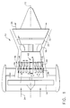
- Figure 1 is a schematic representation of an exemplary turbofan gas turbine engine including a multi-stage axial compressor having a variable stator vane actuation system in accordance with an exemplary embodiment of the present invention.
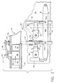
- Figure 2 is a partly sectional axial view of a portion of the compressor illustrated in Figure 1 including the actuation system in accordance with an exemplary embodiment of the present invention.
- Figure 3 is an enlarged, top view of one of the stator vane levers illustrated in Figure 2 joined to a corresponding actuation ring for effecting nonlinear actuation in accordance with the invention.
- Figure 4 is a top view of a stator vane lever in accordance with an alternate embodiment of the present invention.
- Illustrated schematically in Figure 1 is an exemplary aircraft turbofan
gas turbine engine 10 having anaxial centerline axis 12. Theengine 10 includes in serial flow communication afan 14, multi-stageaxial compressor 16,annular combustor 18, high pressure turbine (HPT) 20, and low pressure turbine (LPT) 22 which are axisymmetric about thecenterline axis 12.Ambient air 24 flows through thefan 14 and a portion of which enters thecompressor 16 wherein it is suitably pressurized and channeled to thecombustor 18 wherein it is mixed with fuel and ignited for generatinghot combustion gases 26 which flow downstream through theHPT 20 for powering thecompressor 16 and through theLPT 22 for powering thefan 14 while producing thrust. Thecompressor 16 includes various stages which in turn further pressurize theair 24 therein, some of which stages are variable in accordance with the present invention. - More specifically, and referring to Figure 2, the
compressor 16 includes a plurality of variable stator vanes 28 suitably pivotally mounted in corresponding rows in anannular casing 30. Thevanes 28 cooperate with correspondingcompressor rotor blades 32 arranged in rows and extending radially outwardly from a corresponding compressor spool ordisks 34 which in turn are joined to theHPT 20 illustrated in Figure 1 by a suitable rotor shaft. As theair 24 flows axially downstream fromvane 28 toblade 32 in each of the several axial stages, it is further increased in pressure. - In order to maximize efficiency of the
compressor 16 and maintain a suitable stall margin, thevanes 28 in one or more of the stages are preferably selectively pivotable over a scheduled range of pivot angles A to correspondingly vary the orientation of theindividual vanes 28 relative to the flow ofair 24. - In accordance with the present invention, an improved
actuation system 36 is provided for pivoting thevanes 28 in at least one of the stages for obtaining a nonlinear pivoting schedule relative to other stages having a substantially linear schedule. As shown in Figure 2, a plurality offirst levers 38 are fixedly joined to respective spindles of thestator vanes 28 in one stage for rotating the vanes when desired. Each of thelevers 38 in the exemplary stage illustrated are joined to a first actuation orunison ring 40 which coaxially surrounds thecasing 30 axially adjacent to thelevers 38. - Suitable means 42-are provided for rotating the
ring 40 to in turn rotate thelevers 38 to pivot thevanes 28 in accordance with a predetermined position schedule for maximizing compressor efficiency with a suitable amount of stall margin. The rotatingmeans 42 may take any conventional form, and in the exemplary embodiment illustrated in Figure 2 includes acentral beam 42a extending axially along thecasing 30 and having a proximal end pivotally joined to thecasing 30. Across link 42b extends circumferentially between thering 40 and thebeam 42a and is pivotally joined thereto at its opposite ends. Asuitable actuator 42c, which may be hydraulic, pneumatic, or electric, is operatively joined to a distal end of thebeam 42a to selectively rotate thebeam 42a about its proximal end to in turn rotate thering 40 through thelink 42b. - Another stage of the vanes may be conventionally scheduled or varied using conventional
second levers 44 which are fixedly joined at proximal ends to the vane spindles, and also pivotally joined at their opposite distal ends to a conventional second actuation orunison ring 46. - The
second ring 46 is similarly joined to thecommon beam 42a by another one of thelinks 42b. In the exemplary embodiment illustrated in Figure 2, thesecond ring 46 is located between thefirst ring 40 and the pivot point of thebeam 42a. During operation, theactuator 42c translates the distal end of thebeam 42a causing the beam to pivot around its proximal end. In turn, thelinks 42b cause therespective actuation rings casing 30 to in turn rotate therespective levers respective compressor vanes 28 joined thereto. Since thesecond ring 46 is joined to thebeam 42a closer to its pivot point than thefirst ring 40, the range of rotation of thesecond levers 44 is typically less than the range of rotation of thefirst levers 38. - Furthermore, the actuation system for the
second levers 44 is conventional, with the distal ends of thesecond levers 44 being pivotally mounted to thesecond ring 46. This, therefore, requires that thesecond ring 46 is axially unrestrained so that as thesecond levers 44 rotate, thesecond ring 46 is allowed to freely translate axially to follow the path of thesecond levers 44 as shown in phantom in Figure 2. In this way, substantially linear correspondence between the movement or rotation of thesecond ring 46, and rotation of thesecond levers 44 and attached compressor vanes is obtained. - In accordance with the present invention, it is desired to provide nonlinear scheduling between the
first ring 40 andcorresponding levers 38 to provide additional variability in performance of thecompressor 16 at selected stages as compared to the conventional linear scheduling of other stages such as that actuated by thesecond ring 46. Figure 3 illustrates in more particularity a portion of theactuation system 36 suitably modified for effecting nonlinear scheduling of thecompressor vanes 28 in response to rotation of thefirst ring 40. - Each
lever 38 includes aproximal end 38a which is removably fixedly joined to a respective one of thecompressor vanes 28 in any conventional manner. For example, eachvane 28 includes a spindle extending radially outwardly through thecasing 30 which passes through a corresponding hole in thelever 38 to which it is attached by a suitable retaining nut. Eachlever 38 also includes an oppositedistal end 38b, and acenterline lever axis 38c extending therebetween. By moving or turning thelever 38, the attachedvane 28 pivots over a range of pivot angles A which are conventionally determined for maximizing aerodynamic efficiency of the compressor with suitable stall margin. - A plurality of circumferentially spaced apart
ring guides 48 are fixedly joined to thecasing 30 for guiding circumferential movement or rotation of thefirst ring 40. Means in the form ofslip joints 50 are provided for joining each of the leverdistal ends 38b to thering 40 for varying pivot length B of thelevers 38 as thering 40 is rotated by thebeam 42a. - Figure 3 illustrates in solid line a first position of the
lever 38 having a minimum pivot length B, and in phantom line thelever 38 is disposed in a second position wherein the pivot length is maximum and is designated C. In the exemplary embodiment illustrated in Figure 3, thering guides 48 are joined to thecasing 30 on opposite axial sides of thering 40 to restrain or limit axial movement thereof while permitting primarily only circumferential rotation. Thering guides 48 may include suitable rollers on opposite sides of thering 40 which allow relatively low friction rotation of thering 40 while preventing axial movement thereof. - Whereas the conventional
second ring 46 illustrated in Figure 2 is allowed to translate axially for following movement of thesecond levers 44, thefirst ring 40 illustrated in Figure 3 is prevented from moving axially relative to thefirst levers 38 so that the pivot length may vary for introducing nonlinear response of thefirst levers 38 and attachedvanes 28 relative to the movement or rotation of thefirst ring 40. - In the exemplary embodiment illustrated in Figure 3, each of the
slip joints 50 includes apin 50a engaging anelongate slot 50b disposed between the leverdistal end 38b and thering 40. In this way, thelevers 38 andring 40 are joined together to effect the variable pivot length B, C as thering 40 rotates thelever 38. - In one configuration, the
pin 50a may be fixedly joined to the outer surface of thering 40, and extends radially outwardly. Correspondingly, theslot 50b is disposed in the leverdistal end 38b to slidingly engage thepin 50a extending radially therethrough as thering 40 rotates to vary the position of thelever 38. Theslot 50b has a suitable length D which allows thepin 50a to translate between opposite ends of theslot 50b over the intended maximum range of rotation of thelevers 38. Since thering 40 is axially constrained by thering guides 48, thepin 50a remains in the same axially plane even as thering 40 is rotated. Since thelever 38 rotates relative to the vane spindle at itsproximal end 38a, theslot 50b prevents binding between thelevers 38 and thering 40 and allows thelevers 38 to be turned over their full intended pivoting range, with thepin 50a sliding along the length of theslot 50b. - The slip joint 50 may be otherwise effected by instead mounting the pin to the
individual levers 38 and providing suitable slots in thering 40 itself if desired. Alternatively, the lever distal ends 38b may be mounted in respective end slots in thering 40 for effecting the slip joints and allowing variable pivot length. Yet further, the ring guides 48 may be alternately configured to permit controlled axial movement of thering 40 as it rotates to introduce further nonlinearity in the vane schedule (not shown). - In the exemplary embodiment illustrated in Figure 3, the
lever axis 38c extends longitudinally between the proximal anddistal ends 38a,b thereof and also extends through the centers of the mounting spindle andpin 50a thereat. Rotation of thelever axis 38c therefore directly corresponds with the pivoting angle A as thelever 38 is rotated about its proximal end. Accordingly, the range of the pivoting angle A of thelever 38 through thelever axis 38c is equal to the corresponding pivoting angle A with thevane 28 attached thereto. In this embodiment, each of theslots 50b is disposed in the lever distal ends 38b at least in part along thelever axis 38c for allowing thepins 50a to move or slide in theirrespective slots 50b along thelever axis 38c. - In the exemplary embodiment illustrated in Figure 3, the
slots 50b are straight and aligned coaxially with respective ones of the lever axes 38c. - In an alternate embodiment illustrated in Figure 4, the lever, designated 38B, has a
slot 50b which is straight but skewed circumferentially relative to thelever axis 38c at a skew angle E of about 45°. In this way additional nonlinearity may be introduced as desired. The skew angle E may be positive as shown, or negative for oppositely skewing theslot 50b. In yet another alternate embodiment (not shown), theindividual slots 50b may be curved or arcuate for additionally affecting the nonlinearity in the vane schedule. - The
improved actuation system 36 disclosed above uses basically conventional components for their simplicity and proven effectiveness, with suitable modifications in accordance with the present invention to introduce varying degrees of nonlinearity in scheduling thecompressor vanes 28. The actual vane scheduling is determined for each engine application and desired engine cycle for maximizing compressor efficiency with suitable stall margin. The nonlinearity provided in this schedule by the improved cooperation between thelevers 38 andunison ring 40 allows additional optimization and tailoring of the vane schedule as desired. - Furthermore, one or more of the variable stator vane stages may be modified in accordance with the invention for providing the improved nonlinear vane schedules, while the remaining stator vanes may be conventionally scheduled with the fixed mounted second levers 44 joined to the
common actuation beam 42a. In this way, additional optimization of one or more variable stator vane rows may be accomplished relative to one or more of the adjacent variable stator vane rows that are conventionally scheduled in a substantially linear manner.
Claims (10)
- An actuation system (36) for variable stator vanes (28) pivotally mounted in a casing (30) of a gas turbine engine compressor (16) comprising:a plurality of levers (38) each having a proximal end (38a) fixedly joined to respective ones of said vanes (28), and an opposite distal end (38b), for pivoting said vane (28) as said lever is rotated;an actuation ring (40) coaxially surrounding said casing (30) adjacent said levers (38);a plurality of circumferentially spaced apart ring guides (48) joined to said casing (30) for guiding circumferential rotation of said ring (40); andrespective slip joints (50) joining each of said lever distal ends (38b) to said ring (40) for varying pivot length of said levers 38 as said ring (40) is rotated.
- A system according to claim 1 wherein each of said slip joints (50) comprises a pin (50a) engaging a slot (50b) disposed between said lever distal end 38b and said ring (40) for joining together said lever (38) and ring (40) to effect said variable pivot length as said ring (40) rotates said lever (38).
- A system according to claim 2 wherein:said pin (50a) is fixedly joined to said ring (40) and extends radially; and said slot (50b) is disposed in said lever distal end (38b) to slidingly engage said pin (50a).
- A system according to claim 3 wherein:each of said levers (38) has a longitudinal axis (38c) extending between said proximal and distal ends (38a,b) with which a corresponding vane pivots as said lever (38) is rotated; andeach of said slots (50b) is disposed in said lever distal ends at least in part along said lever axis (38c) for allowing said pins (50a) in said slots (50b) along said lever axes (38c).
- A system according to claim 4 wherein said slots (50b) are aligned coaxially with respective ones of said lever axes (38c).
- A system according to claim 4 wherein said slots (50b) are skewed with respective ones of said lever axes (38c).
- A system according to claim 4 wherein said slots (50b) are straight.
- A system according to claim 4 wherein said ring guides are joined to said casing on opposite axial sides of said ring (40) to constrain axial movement thereof while permitting circumferential rotation thereof.
- A system according to claim 4 further comprising means (42) for rotating said ring (40) to rotate said levers (38) to pivot said vanes (28).
- A system according to claim 9 wherein said rotating means (42) comprise:a beam (42a) extending axially along said casing (30), and having a proximal end pivotally joined to said casing (30);a link (42b) extending circumferentially between said ring (40) and beam (42a), and pivotally joined thereto; andan actuator (42c) joined to a distal end of said beam (42a) to selectively rotate said beam (42a) to rotate said ring (40) through said link (42b).
Applications Claiming Priority (2)
| Application Number | Priority Date | Filing Date | Title |
|---|---|---|---|
| US950084 | 1997-10-14 | ||
| US08/950,084 US5993152A (en) | 1997-10-14 | 1997-10-14 | Nonlinear vane actuation |
Publications (2)
| Publication Number | Publication Date |
|---|---|
| EP0909880A2 true EP0909880A2 (en) | 1999-04-21 |
| EP0909880A3 EP0909880A3 (en) | 2000-02-23 |
Family
ID=25489919
Family Applications (1)
| Application Number | Title | Priority Date | Filing Date |
|---|---|---|---|
| EP98308253A Withdrawn EP0909880A3 (en) | 1997-10-14 | 1998-10-09 | Turbine vane actuation system |
Country Status (3)
| Country | Link |
|---|---|
| US (1) | US5993152A (en) |
| EP (1) | EP0909880A3 (en) |
| JP (1) | JPH11303606A (en) |
Cited By (23)
| Publication number | Priority date | Publication date | Assignee | Title |
|---|---|---|---|---|
| EP1256698A2 (en) * | 2001-05-11 | 2002-11-13 | FIATAVIO S.p.A. | Axial turbine with a variable-geometry stator |
| FR2881190A1 (en) * | 2005-01-21 | 2006-07-28 | Snecma Moteurs Sa | Variable pitch stator guide vane actuating device for e.g. aircraft engine, has actuator fixed to casing and acting on bridge, where device that acts on actuating rings is arranged between rings and does not extend beyond rings |
| EP1724472A2 (en) * | 2005-05-17 | 2006-11-22 | Snecma | Control system for variable guide vane stages of a turbomachine |
| EP1724471A2 (en) * | 2005-05-17 | 2006-11-22 | Snecma | Control system for variable stator vane stages of a turbomachine |
| EP1746261A2 (en) * | 2005-07-20 | 2007-01-24 | United Technologies Corporation | Inner diameter variable vane actuation mechanism |
| EP1867841A1 (en) * | 2006-06-16 | 2007-12-19 | Snecma | Turbomachine stator comprising a stage of synchronising ring vanes activated by a rotating ring gear with automatic centring |
| FR2937678A1 (en) * | 2008-10-23 | 2010-04-30 | Snecma | DEVICE FOR CONTROLLING THE ORIENTATION OF BLOWER BLADES OF A TURBOPROPULSEUR |
| WO2016207513A1 (en) | 2015-06-25 | 2016-12-29 | Safran Aircraft Engines | System for controlling variable-setting blades for a turbine engine |
| EP2971598A4 (en) * | 2013-03-13 | 2017-04-19 | United Technologies Corporation | Variable vane control system |
| EP3228822A1 (en) * | 2016-03-24 | 2017-10-11 | United Technologies Corporation | Variable vane actuation with rotating ring and sliding links |
| US10107130B2 (en) | 2016-03-24 | 2018-10-23 | United Technologies Corporation | Concentric shafts for remote independent variable vane actuation |
| EP3431717A1 (en) * | 2017-06-23 | 2019-01-23 | Rolls-Royce North American Technologies, Inc. | Method and configuration for improved variable vane positioning |
| US10190599B2 (en) | 2016-03-24 | 2019-01-29 | United Technologies Corporation | Drive shaft for remote variable vane actuation |
| US10288087B2 (en) | 2016-03-24 | 2019-05-14 | United Technologies Corporation | Off-axis electric actuation for variable vanes |
| US10294813B2 (en) | 2016-03-24 | 2019-05-21 | United Technologies Corporation | Geared unison ring for variable vane actuation |
| US10301962B2 (en) | 2016-03-24 | 2019-05-28 | United Technologies Corporation | Harmonic drive for shaft driving multiple stages of vanes via gears |
| US10329947B2 (en) | 2016-03-24 | 2019-06-25 | United Technologies Corporation | 35Geared unison ring for multi-stage variable vane actuation |
| US10329946B2 (en) | 2016-03-24 | 2019-06-25 | United Technologies Corporation | Sliding gear actuation for variable vanes |
| US10415596B2 (en) | 2016-03-24 | 2019-09-17 | United Technologies Corporation | Electric actuation for variable vanes |
| US10443431B2 (en) | 2016-03-24 | 2019-10-15 | United Technologies Corporation | Idler gear connection for multi-stage variable vane actuation |
| US10458271B2 (en) | 2016-03-24 | 2019-10-29 | United Technologies Corporation | Cable drive system for variable vane operation |
| CN111288020A (en) * | 2020-02-24 | 2020-06-16 | 中国航发沈阳发动机研究所 | Compressor stator blade linkage structure |
| US20220170381A1 (en) * | 2020-12-01 | 2022-06-02 | Pratt & Whitney Canada Corp. | Variable guide vane assembly and vane arms therefor |
Families Citing this family (36)
| Publication number | Priority date | Publication date | Assignee | Title |
|---|---|---|---|---|
| US6821084B2 (en) | 2002-12-11 | 2004-11-23 | General Electric Company | Torque tube bearing assembly |
| US20050129340A1 (en) * | 2003-12-10 | 2005-06-16 | Arnold Robert A. | Hourglass bearing |
| US7588415B2 (en) * | 2005-07-20 | 2009-09-15 | United Technologies Corporation | Synch ring variable vane synchronizing mechanism for inner diameter vane shroud |
| US7413401B2 (en) * | 2006-01-17 | 2008-08-19 | General Electric Company | Methods and apparatus for controlling variable stator vanes |
| EP1811135A1 (en) * | 2006-01-23 | 2007-07-25 | ABB Turbo Systems AG | Variable guiding device |
| US20100172745A1 (en) * | 2007-04-10 | 2010-07-08 | Elliott Company | Centrifugal compressor having adjustable inlet guide vanes |
| FR2936556B1 (en) * | 2008-09-30 | 2015-07-24 | Snecma | SYSTEM FOR CONTROLLING EQUIPMENT WITH VARIABLE GEOMETRY OF A TURBOMACHINE, IN PARTICULAR BY GUIGNOLS. |
| US20110176913A1 (en) * | 2010-01-19 | 2011-07-21 | Stephen Paul Wassynger | Non-linear asymmetric variable guide vane schedule |
| IT1400053B1 (en) * | 2010-05-24 | 2013-05-17 | Nuovo Pignone Spa | METHODS AND SYSTEMS FOR VARIABLE GEOMETRY ENTRY NOZZLES FOR USE IN TURBOESPANSORI. |
| US20120134783A1 (en) | 2010-11-30 | 2012-05-31 | General Electric Company | System and method for operating a compressor |
| US8909454B2 (en) * | 2011-04-08 | 2014-12-09 | General Electric Company | Control of compression system with independently actuated inlet guide and/or stator vanes |
| US8915703B2 (en) * | 2011-07-28 | 2014-12-23 | United Technologies Corporation | Internally actuated inlet guide vane for fan section |
| DE102012007129A1 (en) * | 2012-04-10 | 2013-10-10 | Rolls-Royce Deutschland Ltd & Co Kg | Guide vane adjusting a gas turbine |
| US9500200B2 (en) * | 2012-04-19 | 2016-11-22 | General Electric Company | Systems and methods for detecting the onset of compressor stall |
| US9885291B2 (en) * | 2012-08-09 | 2018-02-06 | Snecma | Turbomachine comprising a plurality of fixed radial blades mounted upstream of the fan |
| US9879561B2 (en) * | 2012-08-09 | 2018-01-30 | Snecma | Turbomachine comprising a plurality of fixed radial blades mounted upstream of the fan |
| FR3015594B1 (en) * | 2013-12-19 | 2018-04-06 | Safran Aircraft Engines | TURBOMACHINE COMPRESSOR, ESPECIALLY AIRCRAFT TURBOPROPULSER OR AIRCRAFT TURBINEACTOR |
| FR3031772B1 (en) * | 2015-01-19 | 2017-01-13 | Snecma | VARIABLE TIMING AUB CONTROL SYSTEM FOR TURBOMACHINE |
| FR3033007B1 (en) * | 2015-02-19 | 2018-07-13 | Safran Aircraft Engines | DEVICE FOR THE INDIVIDUAL ADJUSTMENT OF A PLURALITY OF FIXED RADIAL BLADES WITH VARIABLE SETTING IN A TURBOMACHINE |
| FR3041714B1 (en) * | 2015-09-30 | 2020-02-14 | Safran Aircraft Engines | TURBOMACHINE COMPRESSOR, ESPECIALLY AN AIRPLANE TURBOPROPELLER OR TURBOREACTOR |
| CN105508299B (en) * | 2016-01-26 | 2018-06-01 | 南通大通宝富风机有限公司 | A kind of single-stage high-speed air blower pilot blade adjusting mechanism |
| US10358934B2 (en) * | 2016-04-11 | 2019-07-23 | United Technologies Corporation | Method and apparatus for adjusting variable vanes |
| GB201610312D0 (en) * | 2016-06-14 | 2016-07-27 | Rolls-Royce Controls And Data Services Ltd | Compressor geometry control |
| US10519797B2 (en) | 2016-06-27 | 2019-12-31 | General Electric Company | Turbine engine and stator vane pitch adjustment system therefor |
| US10563670B2 (en) | 2016-07-29 | 2020-02-18 | Rolls-Royce Corporation | Vane actuation system for a gas turbine engine |
| BE1025470B1 (en) * | 2017-08-14 | 2019-03-18 | Safran Aero Boosters S.A. | COMPRESSOR VARIABLE SHAFT AUB SYSTEM FOR TURBOMACHINE |
| US10508660B2 (en) | 2017-10-20 | 2019-12-17 | Rolls-Royce Corporation | Apparatus and method for positioning a variable vane |
| US10704411B2 (en) | 2018-08-03 | 2020-07-07 | General Electric Company | Variable vane actuation system for a turbo machine |
| FR3107319B1 (en) * | 2020-02-19 | 2022-08-12 | Safran Aircraft Engines | TURBOMACHINE MODULE EQUIPPED WITH STATOR BLADE PITCH CHANGE SYSTEM |
| US20220341342A1 (en) * | 2021-04-21 | 2022-10-27 | General Electric Company | Variable vane apparatus |
| PL437817A1 (en) * | 2021-05-07 | 2022-11-14 | General Electric Company | Variable geometry split-action system for a turbine engine compressor |
| US11560810B1 (en) | 2021-07-20 | 2023-01-24 | Rolls-Royce North American Technologies Inc. | Variable vane actuation system and method for gas turbine engine performance management |
| US11788429B2 (en) * | 2021-08-25 | 2023-10-17 | Rolls-Royce Corporation | Variable tandem fan outlet guide vanes |
| US11802490B2 (en) * | 2021-08-25 | 2023-10-31 | Rolls-Royce Corporation | Controllable variable fan outlet guide vanes |
| DE102022118786A1 (en) | 2022-07-27 | 2024-02-01 | MTU Aero Engines AG | Device for adjusting a plurality of guide vanes of a variable compressor stage for an axial compressor of a turbomachine, and a turbomachine |
| US11834966B1 (en) | 2022-12-30 | 2023-12-05 | Rolls-Royce North American Technologies Inc. | Systems and methods for multi-dimensional variable vane stage rigging utilizing adjustable alignment mechanisms |
Citations (6)
| Publication number | Priority date | Publication date | Assignee | Title |
|---|---|---|---|---|
| US2305311A (en) * | 1937-07-07 | 1942-12-15 | Jendrassik George | Gas turbine plant equipped with regulating apparatus |
| US2778564A (en) * | 1953-12-01 | 1957-01-22 | Havilland Engine Co Ltd | Stator blade ring assemblies for axial flow compressors and the like |
| US3224194A (en) * | 1963-06-26 | 1965-12-21 | Curtiss Wright Corp | Gas turbine engine |
| US3685920A (en) * | 1971-02-01 | 1972-08-22 | Gen Electric | Actuation ring for variable geometry compressors or gas turbine engines |
| US3954349A (en) * | 1975-06-02 | 1976-05-04 | United Technologies Corporation | Lever connection to syncring |
| GB2187237A (en) * | 1986-02-28 | 1987-09-03 | Mtu Muenchen Gmbh | Independently adjustable vanes of a tandem guide vane array in a turbocompressor |
Family Cites Families (6)
| Publication number | Priority date | Publication date | Assignee | Title |
|---|---|---|---|---|
| FR1153404A (en) * | 1950-09-01 | 1958-03-10 | Austin Motor Co Ltd | Transmission systems for road or rail vehicles, turbine operated |
| GB757230A (en) * | 1953-12-01 | 1956-09-19 | Havilland Engine Co Ltd | Improvements in or relating to stator blade ring assemblies for axial flow compressors and the like |
| US3066488A (en) * | 1959-11-04 | 1962-12-04 | Bendix Corp | Power output control for a gas turbine engine |
| US3314595A (en) * | 1965-06-09 | 1967-04-18 | Gen Electric | Adjustment mechanism for axial flow compressors |
| US3990809A (en) * | 1975-07-24 | 1976-11-09 | United Technologies Corporation | High ratio actuation linkage |
| GB2078865B (en) * | 1980-06-28 | 1983-06-08 | Rolls Royce | A variable stator vane operating mechanism for a gas turbine engine |
-
1997
- 1997-10-14 US US08/950,084 patent/US5993152A/en not_active Expired - Fee Related
-
1998
- 1998-10-09 EP EP98308253A patent/EP0909880A3/en not_active Withdrawn
- 1998-10-12 JP JP10288585A patent/JPH11303606A/en not_active Withdrawn
Patent Citations (6)
| Publication number | Priority date | Publication date | Assignee | Title |
|---|---|---|---|---|
| US2305311A (en) * | 1937-07-07 | 1942-12-15 | Jendrassik George | Gas turbine plant equipped with regulating apparatus |
| US2778564A (en) * | 1953-12-01 | 1957-01-22 | Havilland Engine Co Ltd | Stator blade ring assemblies for axial flow compressors and the like |
| US3224194A (en) * | 1963-06-26 | 1965-12-21 | Curtiss Wright Corp | Gas turbine engine |
| US3685920A (en) * | 1971-02-01 | 1972-08-22 | Gen Electric | Actuation ring for variable geometry compressors or gas turbine engines |
| US3954349A (en) * | 1975-06-02 | 1976-05-04 | United Technologies Corporation | Lever connection to syncring |
| GB2187237A (en) * | 1986-02-28 | 1987-09-03 | Mtu Muenchen Gmbh | Independently adjustable vanes of a tandem guide vane array in a turbocompressor |
Cited By (45)
| Publication number | Priority date | Publication date | Assignee | Title |
|---|---|---|---|---|
| EP1256698A2 (en) * | 2001-05-11 | 2002-11-13 | FIATAVIO S.p.A. | Axial turbine with a variable-geometry stator |
| EP1256698A3 (en) * | 2001-05-11 | 2004-03-10 | AVIO S.p.A. | Axial turbine with a variable-geometry stator |
| US6860717B2 (en) | 2001-05-11 | 2005-03-01 | Avio S.P.A. | Axial turbine for aeronautical applications |
| FR2881190A1 (en) * | 2005-01-21 | 2006-07-28 | Snecma Moteurs Sa | Variable pitch stator guide vane actuating device for e.g. aircraft engine, has actuator fixed to casing and acting on bridge, where device that acts on actuating rings is arranged between rings and does not extend beyond rings |
| US7322790B2 (en) | 2005-05-17 | 2008-01-29 | Snecma | System for controlling stages of variable-pitch stator vanes in a turbomachine |
| FR2885969A1 (en) * | 2005-05-17 | 2006-11-24 | Snecma Moteurs Sa | TURBOMACHINE VARIABLE ROTATION ANGLE STATOR AUTONER STAGE CONTROL SYSTEM |
| FR2885968A1 (en) * | 2005-05-17 | 2006-11-24 | Snecma Moteurs Sa | TURBOMACHINE VARIABLE ROTATION ANGLE STATOR AUTONER STAGE CONTROL SYSTEM |
| US7273346B2 (en) | 2005-05-17 | 2007-09-25 | Snecma | System for controlling stages of variable-pitch stator vanes in a turbomachine |
| EP1724471A2 (en) * | 2005-05-17 | 2006-11-22 | Snecma | Control system for variable stator vane stages of a turbomachine |
| EP1724472A2 (en) * | 2005-05-17 | 2006-11-22 | Snecma | Control system for variable guide vane stages of a turbomachine |
| EP1724472A3 (en) * | 2005-05-17 | 2009-01-21 | Snecma | Control system for variable guide vane stages of a turbomachine |
| EP1724471A3 (en) * | 2005-05-17 | 2009-01-21 | Snecma | Control system for variable stator vane stages of a turbomachine |
| EP1746261A3 (en) * | 2005-07-20 | 2010-04-21 | United Technologies Corporation | Inner diameter variable vane actuation mechanism |
| EP1746261A2 (en) * | 2005-07-20 | 2007-01-24 | United Technologies Corporation | Inner diameter variable vane actuation mechanism |
| EP2522815A1 (en) * | 2005-07-20 | 2012-11-14 | United Technologies Corporation | Inner diameter variable vane actuation mechanism |
| EP1867841A1 (en) * | 2006-06-16 | 2007-12-19 | Snecma | Turbomachine stator comprising a stage of synchronising ring vanes activated by a rotating ring gear with automatic centring |
| US7938620B2 (en) | 2006-06-16 | 2011-05-10 | Snecma | Turbomachine stator including a stage of stator vanes actuated by an automatically centered rotary ring |
| FR2902454A1 (en) * | 2006-06-16 | 2007-12-21 | Snecma Sa | TURBOMACHINE STATOR COMPRISING A FLOOR OF ADJUSTERS ADJUSTED BY A ROTATING CROWN WITH AUTOMATIC CENTERING |
| FR2937678A1 (en) * | 2008-10-23 | 2010-04-30 | Snecma | DEVICE FOR CONTROLLING THE ORIENTATION OF BLOWER BLADES OF A TURBOPROPULSEUR |
| EP2971598A4 (en) * | 2013-03-13 | 2017-04-19 | United Technologies Corporation | Variable vane control system |
| US10060285B2 (en) | 2013-03-13 | 2018-08-28 | United Technologies Corporation | Variable vane control system |
| US10648359B2 (en) | 2015-06-25 | 2020-05-12 | Safran Aircraft Engines | System for controlling variable-setting blades for a turbine engine |
| WO2016207513A1 (en) | 2015-06-25 | 2016-12-29 | Safran Aircraft Engines | System for controlling variable-setting blades for a turbine engine |
| FR3038018A1 (en) * | 2015-06-25 | 2016-12-30 | Snecma | VARIABLE TIMING AUB CONTROL SYSTEM FOR TURBOMACHINE |
| CN107771250A (en) * | 2015-06-25 | 2018-03-06 | 赛峰飞机发动机公司 | The system for being used to control adjustable setting blade for turbogenerator |
| EP3228822A1 (en) * | 2016-03-24 | 2017-10-11 | United Technologies Corporation | Variable vane actuation with rotating ring and sliding links |
| US10443431B2 (en) | 2016-03-24 | 2019-10-15 | United Technologies Corporation | Idler gear connection for multi-stage variable vane actuation |
| US10190599B2 (en) | 2016-03-24 | 2019-01-29 | United Technologies Corporation | Drive shaft for remote variable vane actuation |
| US10288087B2 (en) | 2016-03-24 | 2019-05-14 | United Technologies Corporation | Off-axis electric actuation for variable vanes |
| US10294813B2 (en) | 2016-03-24 | 2019-05-21 | United Technologies Corporation | Geared unison ring for variable vane actuation |
| US10301962B2 (en) | 2016-03-24 | 2019-05-28 | United Technologies Corporation | Harmonic drive for shaft driving multiple stages of vanes via gears |
| US10329947B2 (en) | 2016-03-24 | 2019-06-25 | United Technologies Corporation | 35Geared unison ring for multi-stage variable vane actuation |
| US10329946B2 (en) | 2016-03-24 | 2019-06-25 | United Technologies Corporation | Sliding gear actuation for variable vanes |
| US10415596B2 (en) | 2016-03-24 | 2019-09-17 | United Technologies Corporation | Electric actuation for variable vanes |
| US11131323B2 (en) | 2016-03-24 | 2021-09-28 | Raytheon Technologies Corporation | Harmonic drive for shaft driving multiple stages of vanes via gears |
| US10443430B2 (en) | 2016-03-24 | 2019-10-15 | United Technologies Corporation | Variable vane actuation with rotating ring and sliding links |
| US10458271B2 (en) | 2016-03-24 | 2019-10-29 | United Technologies Corporation | Cable drive system for variable vane operation |
| US10107130B2 (en) | 2016-03-24 | 2018-10-23 | United Technologies Corporation | Concentric shafts for remote independent variable vane actuation |
| US10634000B2 (en) | 2017-06-23 | 2020-04-28 | Rolls-Royce North American Technologies Inc. | Method and configuration for improved variable vane positioning |
| EP3431717A1 (en) * | 2017-06-23 | 2019-01-23 | Rolls-Royce North American Technologies, Inc. | Method and configuration for improved variable vane positioning |
| CN111288020A (en) * | 2020-02-24 | 2020-06-16 | 中国航发沈阳发动机研究所 | Compressor stator blade linkage structure |
| CN111288020B (en) * | 2020-02-24 | 2021-05-28 | 中国航发沈阳发动机研究所 | Compressor stator blade linkage structure |
| US20220170381A1 (en) * | 2020-12-01 | 2022-06-02 | Pratt & Whitney Canada Corp. | Variable guide vane assembly and vane arms therefor |
| EP4008884A1 (en) * | 2020-12-01 | 2022-06-08 | Pratt & Whitney Canada Corp. | Variable guide vane assembly for a gas turbine engine and gas turbine engine |
| US11371380B2 (en) * | 2020-12-01 | 2022-06-28 | Pratt & Whitney Canada Corp. | Variable guide vane assembly and vane arms therefor |
Also Published As
| Publication number | Publication date |
|---|---|
| US5993152A (en) | 1999-11-30 |
| JPH11303606A (en) | 1999-11-02 |
| EP0909880A3 (en) | 2000-02-23 |
Similar Documents
| Publication | Publication Date | Title |
|---|---|---|
| US5993152A (en) | Nonlinear vane actuation | |
| EP1808579B1 (en) | Actuation system for variable stator vanes | |
| EP1835147B1 (en) | Fan assembly and corresponding gas turbine engine | |
| EP1122407B1 (en) | Controllable guide vane apparatus for a gas turbine engine | |
| US10288083B2 (en) | Pitch range for a variable pitch fan | |
| US7628579B2 (en) | Gear train variable vane synchronizing mechanism for inner diameter vane shroud | |
| EP2971599B1 (en) | Variable vane drive system | |
| US20140064912A1 (en) | Systems and Methods to Control Variable Stator Vanes in Gas Turbine Engines | |
| EP3093451B1 (en) | Blade outer air seal assembly, corresponding gas turbine engine and method for controlling | |
| US20140314540A1 (en) | Gas turbine engine synchronization ring | |
| EP3453839A2 (en) | Gas turbine engine blade outer air seal | |
| US11092167B2 (en) | Variable vane actuating system | |
| US10794272B2 (en) | Axial and centrifugal compressor | |
| EP2703606A1 (en) | System and method to control variable stator vanes in gas turbine engines | |
| US20210140331A1 (en) | Vane arm load spreader | |
| US20210079805A1 (en) | Vane arm for variable vanes | |
| EP3617462A1 (en) | Variable vane actuating system | |
| US8851832B2 (en) | Engine and vane actuation system for turbine engine | |
| US20140064910A1 (en) | Systems and Methods to Control Variable Stator Vanes in Gas Turbine Engines | |
| US20210071672A1 (en) | Gas turbine engine operating point | |
| EP3591208A1 (en) | Aircraft engine fan | |
| US20230167745A1 (en) | Gas turbine engine including a rotating blade assembly | |
| GB2589098A (en) | Variable vane mechanism | |
| US20140205424A1 (en) | Systems and Methods to Control Variable Stator Vanes in Gas Turbine Engines |
Legal Events
| Date | Code | Title | Description |
|---|---|---|---|
| PUAI | Public reference made under article 153(3) epc to a published international application that has entered the european phase |
Free format text: ORIGINAL CODE: 0009012 |
|
| AK | Designated contracting states |
Kind code of ref document: A2 Designated state(s): DE FR GB IT |
|
| AX | Request for extension of the european patent |
Free format text: AL;LT;LV;MK;RO;SI |
|
| PUAL | Search report despatched |
Free format text: ORIGINAL CODE: 0009013 |
|
| AK | Designated contracting states |
Kind code of ref document: A3 Designated state(s): AT BE CH CY DE DK ES FI FR GB GR IE IT LI LU MC NL PT SE |
|
| AX | Request for extension of the european patent |
Free format text: AL;LT;LV;MK;RO;SI |
|
| 17P | Request for examination filed |
Effective date: 20000823 |
|
| AKX | Designation fees paid |
Free format text: DE FR GB IT |
|
| 17Q | First examination report despatched |
Effective date: 20020306 |
|
| STAA | Information on the status of an ep patent application or granted ep patent |
Free format text: STATUS: THE APPLICATION IS DEEMED TO BE WITHDRAWN |
|
| 18D | Application deemed to be withdrawn |
Effective date: 20031216 |