EP1745528B1 - Sealed plug-in connection that runs through a dividing wall and corresponding mounting method - Google Patents
Sealed plug-in connection that runs through a dividing wall and corresponding mounting method Download PDFInfo
- Publication number
- EP1745528B1 EP1745528B1 EP05716340A EP05716340A EP1745528B1 EP 1745528 B1 EP1745528 B1 EP 1745528B1 EP 05716340 A EP05716340 A EP 05716340A EP 05716340 A EP05716340 A EP 05716340A EP 1745528 B1 EP1745528 B1 EP 1745528B1
- Authority
- EP
- European Patent Office
- Prior art keywords
- connector
- plug
- plug connection
- sealing
- partition
- Prior art date
- Legal status (The legal status is an assumption and is not a legal conclusion. Google has not performed a legal analysis and makes no representation as to the accuracy of the status listed.)
- Expired - Lifetime
Links
- 238000005192 partition Methods 0.000 claims abstract description 71
- 238000007789 sealing Methods 0.000 claims abstract description 42
- 230000013011 mating Effects 0.000 claims description 19
- 230000033001 locomotion Effects 0.000 claims description 12
- 238000010276 construction Methods 0.000 claims 1
- 230000000149 penetrating effect Effects 0.000 description 4
- 230000000903 blocking effect Effects 0.000 description 3
- 238000006073 displacement reaction Methods 0.000 description 3
- 238000009434 installation Methods 0.000 description 3
- 238000005304 joining Methods 0.000 description 3
- 238000005452 bending Methods 0.000 description 2
- 230000005540 biological transmission Effects 0.000 description 2
- 230000008878 coupling Effects 0.000 description 2
- 238000010168 coupling process Methods 0.000 description 2
- 238000005859 coupling reaction Methods 0.000 description 2
- 230000035515 penetration Effects 0.000 description 2
- 230000009467 reduction Effects 0.000 description 2
- 239000000243 solution Substances 0.000 description 2
- 230000035882 stress Effects 0.000 description 2
- XLYOFNOQVPJJNP-UHFFFAOYSA-N water Substances O XLYOFNOQVPJJNP-UHFFFAOYSA-N 0.000 description 2
- 230000008901 benefit Effects 0.000 description 1
- 230000000295 complement effect Effects 0.000 description 1
- 238000013461 design Methods 0.000 description 1
- 238000011161 development Methods 0.000 description 1
- 230000018109 developmental process Effects 0.000 description 1
- 238000002347 injection Methods 0.000 description 1
- 239000007924 injection Substances 0.000 description 1
- 238000003780 insertion Methods 0.000 description 1
- 230000037431 insertion Effects 0.000 description 1
- 230000007774 longterm Effects 0.000 description 1
- 238000004519 manufacturing process Methods 0.000 description 1
- 230000007246 mechanism Effects 0.000 description 1
- 230000002093 peripheral effect Effects 0.000 description 1
- 238000003825 pressing Methods 0.000 description 1
- 230000008439 repair process Effects 0.000 description 1
- 229920002379 silicone rubber Polymers 0.000 description 1
- 239000004945 silicone rubber Substances 0.000 description 1
- 239000011343 solid material Substances 0.000 description 1
- 230000008646 thermal stress Effects 0.000 description 1
- 238000013519 translation Methods 0.000 description 1
Images


Classifications
-
- H—ELECTRICITY
- H01—ELECTRIC ELEMENTS
- H01R—ELECTRICALLY-CONDUCTIVE CONNECTIONS; STRUCTURAL ASSOCIATIONS OF A PLURALITY OF MUTUALLY-INSULATED ELECTRICAL CONNECTING ELEMENTS; COUPLING DEVICES; CURRENT COLLECTORS
- H01R13/00—Details of coupling devices of the kinds covered by groups H01R12/70 or H01R24/00 - H01R33/00
- H01R13/46—Bases; Cases
- H01R13/52—Dustproof, splashproof, drip-proof, waterproof, or flameproof cases
- H01R13/5202—Sealing means between parts of housing or between housing part and a wall, e.g. sealing rings
-
- H—ELECTRICITY
- H01—ELECTRIC ELEMENTS
- H01R—ELECTRICALLY-CONDUCTIVE CONNECTIONS; STRUCTURAL ASSOCIATIONS OF A PLURALITY OF MUTUALLY-INSULATED ELECTRICAL CONNECTING ELEMENTS; COUPLING DEVICES; CURRENT COLLECTORS
- H01R13/00—Details of coupling devices of the kinds covered by groups H01R12/70 or H01R24/00 - H01R33/00
- H01R13/62—Means for facilitating engagement or disengagement of coupling parts or for holding them in engagement
- H01R13/629—Additional means for facilitating engagement or disengagement of coupling parts, e.g. aligning or guiding means, levers, gas pressure electrical locking indicators, manufacturing tolerances
- H01R13/62905—Additional means for facilitating engagement or disengagement of coupling parts, e.g. aligning or guiding means, levers, gas pressure electrical locking indicators, manufacturing tolerances comprising a camming member
- H01R13/62911—U-shaped sliding element
-
- H—ELECTRICITY
- H01—ELECTRIC ELEMENTS
- H01R—ELECTRICALLY-CONDUCTIVE CONNECTIONS; STRUCTURAL ASSOCIATIONS OF A PLURALITY OF MUTUALLY-INSULATED ELECTRICAL CONNECTING ELEMENTS; COUPLING DEVICES; CURRENT COLLECTORS
- H01R13/00—Details of coupling devices of the kinds covered by groups H01R12/70 or H01R24/00 - H01R33/00
- H01R13/62—Means for facilitating engagement or disengagement of coupling parts or for holding them in engagement
- H01R13/629—Additional means for facilitating engagement or disengagement of coupling parts, e.g. aligning or guiding means, levers, gas pressure electrical locking indicators, manufacturing tolerances
- H01R13/62933—Comprising exclusively pivoting lever
- H01R13/62944—Pivoting lever comprising gear teeth
-
- H—ELECTRICITY
- H01—ELECTRIC ELEMENTS
- H01R—ELECTRICALLY-CONDUCTIVE CONNECTIONS; STRUCTURAL ASSOCIATIONS OF A PLURALITY OF MUTUALLY-INSULATED ELECTRICAL CONNECTING ELEMENTS; COUPLING DEVICES; CURRENT COLLECTORS
- H01R13/00—Details of coupling devices of the kinds covered by groups H01R12/70 or H01R24/00 - H01R33/00
- H01R13/73—Means for mounting coupling parts to apparatus or structures, e.g. to a wall
- H01R13/74—Means for mounting coupling parts in openings of a panel
-
- H—ELECTRICITY
- H01—ELECTRIC ELEMENTS
- H01R—ELECTRICALLY-CONDUCTIVE CONNECTIONS; STRUCTURAL ASSOCIATIONS OF A PLURALITY OF MUTUALLY-INSULATED ELECTRICAL CONNECTING ELEMENTS; COUPLING DEVICES; CURRENT COLLECTORS
- H01R13/00—Details of coupling devices of the kinds covered by groups H01R12/70 or H01R24/00 - H01R33/00
- H01R13/62—Means for facilitating engagement or disengagement of coupling parts or for holding them in engagement
- H01R13/629—Additional means for facilitating engagement or disengagement of coupling parts, e.g. aligning or guiding means, levers, gas pressure electrical locking indicators, manufacturing tolerances
- H01R13/62905—Additional means for facilitating engagement or disengagement of coupling parts, e.g. aligning or guiding means, levers, gas pressure electrical locking indicators, manufacturing tolerances comprising a camming member
- H01R13/62927—Comprising supplementary or additional locking means
-
- H—ELECTRICITY
- H01—ELECTRIC ELEMENTS
- H01R—ELECTRICALLY-CONDUCTIVE CONNECTIONS; STRUCTURAL ASSOCIATIONS OF A PLURALITY OF MUTUALLY-INSULATED ELECTRICAL CONNECTING ELEMENTS; COUPLING DEVICES; CURRENT COLLECTORS
- H01R13/00—Details of coupling devices of the kinds covered by groups H01R12/70 or H01R24/00 - H01R33/00
- H01R13/62—Means for facilitating engagement or disengagement of coupling parts or for holding them in engagement
- H01R13/629—Additional means for facilitating engagement or disengagement of coupling parts, e.g. aligning or guiding means, levers, gas pressure electrical locking indicators, manufacturing tolerances
- H01R13/62933—Comprising exclusively pivoting lever
- H01R13/62955—Pivoting lever comprising supplementary/additional locking means
-
- H—ELECTRICITY
- H01—ELECTRIC ELEMENTS
- H01R—ELECTRICALLY-CONDUCTIVE CONNECTIONS; STRUCTURAL ASSOCIATIONS OF A PLURALITY OF MUTUALLY-INSULATED ELECTRICAL CONNECTING ELEMENTS; COUPLING DEVICES; CURRENT COLLECTORS
- H01R13/00—Details of coupling devices of the kinds covered by groups H01R12/70 or H01R24/00 - H01R33/00
- H01R13/73—Means for mounting coupling parts to apparatus or structures, e.g. to a wall
- H01R13/74—Means for mounting coupling parts in openings of a panel
- H01R13/741—Means for mounting coupling parts in openings of a panel using snap fastening means
Definitions
- the present invention relates to a connector for making at least one electrical connection through an opening of a partition.
- the connector which is also referred to as a through-connector, has a first and a second connector which can be plugged together and at least one of the connectors can be sealed against the partition wall via a seal enclosing the opening.
- the present invention relates to a connector in which at least one of the plugs has a tensioning device which can be brought into engagement with the other plug and with which the two plugs are permanently tensioned in their mating direction by incorporating the partition wall.
- the invention further relates to a mounting method for producing such an electrical connector.
- both connector housings each have a sealing device for sealing against the partition wall and a pivotable clamping device is provided to press the two parts of the connector in the assembled state sealed to the wall.
- a pivoting lever with a cam groove on the first connector cooperates with a cam follower on the second connector to press the two connectors together.
- the DE 298 23 075 U1 relates to a connector housing coupling having a plug-in base housing and a plug-in counter housing, which together each connected through a wall.
- a latching device for latched fixing of the base housing in the opening of the partition wall is provided and on the mating housing locking devices are present, which cooperate in the mated state of the housing with this latching device so that the latching device is held in the latched position immobile.
- a second locking device is provided by means of which the two housing parts are releasably locked together in the assembled state.
- an electrical connector assembly is known in which the complete mating of two connector parts, an operator actuates a pivotable lever which is provided with teeth which cooperate for moving the two connector parts to each other with associated racks.
- a pivotal movement of the lever is translated into a linear motion for mating the two connectors.
- the invention is therefore based on the object to improve a generic connector of the type mentioned in that the tightness against the environment and the reliability of the connection can be increased.
- the present invention is based on the basic idea that an undesirable penetration of moisture into the interior of the connector can be avoided by sealing the connection region between the clamping device and the at least one connector by means of a sealing device.
- the tensioning device has at least one actuating projection, which cooperates for tensioning the plug with a receptacle which is arranged on one of the plugs. In this way can be done in a very simple manner, a translation of the expended during clamping force in a clamping force.
- the tensioning device can have a locking lever, which is pivotable for tensioning the two plugs about an axis of rotation which runs approximately transversely to the direction of passage through the dividing wall. In such an arrangement, it is sufficient to seal the area in which the locking lever is rotatably mounted.
- At least one tooth with involute tooth flanks can be arranged on the bearing projections as the actuating projection.
- the tensioning device may comprise a locking lever having a base portion and two leg portions. At the leg portions bearing projections are formed, which are rotatably mounted in corresponding bearing recesses of a plug. In this way it can be realized in a particularly simple manner that the locking lever for clamping the connector about an axis of rotation, which extends approximately transversely to the direction of passage through the partition, is pivotable.
- the sealing device can then be arranged on the bearing projections, for example in the form of an O-ring, or it is alternatively injection-molded directly onto the bearing projections.
- a particularly cost-effective and simple realization of the sealing device according to the invention is given when the sealing device is formed by an elastic O-ring.
- the seal opposite the dividing wall must be mounted circumferentially around the opening in the dividing wall.
- the seal can be sprayed onto the outer periphery of the plug, so that the seal is captively attached to the connector housing.
- the connection between the seal and the plug on which it is molded always completely tight.
- this seal can also be a separate part that can be brought into contact with both the plug and the partition.
- a separate locking device also referred to as connector position assurance (CPA) may be provided for locking the tensioning device in a final assembled condition.
- CPA connector position assurance
- the securing device is released when it is displaceable in a direction transverse to the direction of passage through the partition wall.
- a locking lug which is provided for locking the tensioning device on the securing device, represents a particularly effective and easily realizable possibility of locking.
- the tensioning device may be a sliding device with at least one transmission or reduction arrangement. This allows converting an applied pushing force or movement into a greater or lesser clamping force or movement.
- the tensioning device may be a sliding device, which is displaceable in a direction approximately transverse to the direction of passage through the partition wall for tensioning the plug.
- the tensioning device may comprise at least one guide rail, which extends partially in a plane along the Caribbeansteckraum and approximately transversely to the mating direction. This is a sliding force or movement in a clamping force or movement convertible.
- a clamping device designed as a sliding device can be sealed particularly effectively against penetrating moisture.
- a seal can for example be injected and to improve the tightness and more complicated cross-sections, z. B. having at least one sealing lip.
- a particularly secure and realized with little effort seal can be achieved if at least one sealing projection is formed on a second connector housing, which cooperates for sealing the connector with the sealing device.
- a locking device which is movable between a locked position in which the second connector is fixed to the partition, and an unlocked position, a particularly secure fixation of the second connector can be achieved on the partition.
- a locking device which can also be referred to as a further connector position assurance (CPA)
- CPA connector position assurance
- the second connector can be easily removed from the partition wall.
- CPA connector position assurance
- if greater forces must be expended when plugging in the first plug it can be ensured that the second plug is not unintentionally released from the partition wall.
- this second plug is held in a body panel whose rear side is no longer readily accessible at the time of mating, as is the case for example in a car door, can be avoided with the inventive solution that the second plug no longer properly can be contacted.
- At least one latching device can be arranged on the locking device in order to secure the locking device in cooperation with an associated latching opening in the locked position. This is particularly important in applications in the automotive sector, because strong mechanical and thermal stresses occur during operation.
- the locking device can not move unintentionally from the unlocked position, the at least one locking device in the unlocked position cooperate with another associated locking opening to fix the locking device in this position.
- this locking connection from the outside (at least for a suitable tool) accessible so that it is solvable in the case of a desired expansion.
- the locking device may be displaceable in the simplest case with respect to the second connector in the direction of joining the two connectors.
- this solution has the disadvantage that it can not be ensured that the two plugs are pluggable only when the locking device is properly in its locked position.
- the locking device may be mounted by means of a hinge-like connection to the second connector housing and between the locked and the unlocked position by a pivoting movement about an axis which extends approximately transversely to the direction of passage through the partition to be movable.
- an edge region lying opposite the axis of rotation in the unlocked state can thus be arranged in the second connector housing such that the two connectors can not be plugged together.
- a connector 100 has reference to FIG Fig. 1 a first plug 1 and a second plug 17.
- the second plug 17 is mounted in a partition wall 37.
- the second connector 17 is a male connector and the first connector 1 is the associated female connector, which is not essential to the present invention since the arrangement of pins and sockets could be reversed.
- the first plug 1 is sealed by means of a circumferential seal 28 against the partition wall 37.
- the connector 100 has a clamping device 160, which in the in Fig. 1 shown final assembled position, the two plugs 37 braced against each other involving the partition wall.
- a locking lever 160 serves as a clamping device.
- the first connector 1 has a first connector housing 2, a nozzle 7 to which a nozzle can be attached, a first pin receptacle 5, and a second pin receptacle 6.
- the nozzle which is not shown here, as well as the nozzle 7 are part of a channel through which a cable, not shown, is insertable into the interior of the first connector housing 2.
- the first connector 1 has a sealing device 162.
- This sealing device is realized in the arrangement shown by a simple O-ring. Of course, however, other possibilities for producing the sealing device can be used, such as molded seals or more complex shaped seals, the z. B. have sealing lips.
- the seal on a bearing projection 164 is arranged, which holds the locking lever 160 pivotally in the direction 166 in a bearing receptacle 168 of the first connector housing 2. Due to the special shape of the sealing device 162 as an O-ring seal despite the mobility of the locking lever 160 can be ensured in a particularly simple manner.
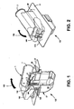
- the connector 100 in the Fig. 2 shown again in a rotated perspective view.
- the securing device 170 has a latching lug 172 for latching with the latching opening 174 of the locking lever 160.
- Fig. 3 the connector is shown in the unmated state.
- the second plug 17 is already mounted in the partition wall 37.
- additional space can be saved, since the second plug 17 in this "parking position" not yet must firmly abut the partition wall 37, but, if necessary, is still slidably mounted. Only when closing the Contact with the first connector 1 and when clamping the contact by means of the locking lever 160, the second connector 17 is attracted to the partition wall 37 and pressed.
- the receptacle 176 allows engagement of an integrally formed on the Verrieglungshebel actuating projection 178 for tensioning the two connectors to the partition wall 37 (see Fig. 4 ).
- the engagement member 176 is formed as a reduced rack, which cooperates with the actuating element 178, which is designed as part of a gear.
- a locking device 102 is furthermore provided whose mode of operation is to lock in the locked state a deflection of the latching arm 152 inwards, so that the plug 17 can not fall out of the opening.
- the resilient locking arm 152 is integrally formed in the embodiment shown on the plastic housing of the second connector.
- the locking device 102 has a latching lug 110 which locks both in the locked and in the unlocked state in a corresponding latching opening 124 and 126, so that the locking device 102 is captively secured in two positions.
- the locking device 102 is movable between the locked and the unlocked position in the direction 150, that is, in the direction of joining the two plugs 1 and 17. This is particularly advantageous because the locking device is thus particularly easy to access from the outside and easily locked by an operator and can also be solved again.
- Two elongate cutouts 154 also allow for flexible mobility of the detent 110.
- An actuating projection 156 facilitates operation of the locking device 102 by a user.
- the surfaces 158 (see Fig. 5 ) provide in the locked state for the blocking of the locking hooks 131.
- a drip protection cap 26 covers the second plug 17 and thus protects against the ingress of dripping water.
- the first connector 1 is shown here with the locking lever 160 pivoted upwards.
- the securing device 170 which is mounted displaceably on the housing 2, is located in the illustration shown in a position in which, during the later pivoting of the locking lever 160, latching with the latching lug 172 is made possible.
- the securing device 170 can be pushed in the direction 182, whereby the locking lug 172 engages the projection 184 on the locking lever 160 and holds it securely in its locked position.
- An actuating projection 186 facilitates the displacement of the securing device 170.
- the securing device is furthermore held displaceably in corresponding grooves on the housing 2.
- a securing tab is formed on the securing device 170, which prevents displacement of the securing device in the direction 182 until it is pressed by the folded-down locking lever 160 to the housing 2 and allows the securing tab 188 is displaceable in the groove 190.
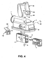
- Fig. 4 shows the first connector 1 in an exploded view. How out Fig. 4 can be seen, the first and the second pin receptacle 5, 6 sections complementary to each other, so that the first pin receptacle 5 in sections in the direction of arrow 8 in the second pin receptacle 6 is inserted. In the assembled state, the first and the second pin receptacle 5, 6 in the direction of arrow 9 in the interior of the first connector housing 2 can be inserted.
- a latching device 192 ensures a secure hold in the first connector housing 2.
- the first connector housing according to the invention has approximately circular bearing recesses 168, through which the bearing projections 164 penetrate and allow rotation about the dashed line indicated axis 180.
- the locking lever 160 has a substantially U-shaped configuration with two legs on which the bearing projections 164 are formed, and a base, which engages with the securing device 170 on. Due to the fact that the locking lever 160 partially surrounds the housing 2, the most space-saving possible arrangement can be realized.
- actuating element 178 On the bearing projection 164, a part of a gear wheel is in each case formed as an actuating element 178, which engages with corresponding engagement elements 176 on the second connector housing 25.
- the actuating element 178 is formed as part of an involute toothing and the tooth flank 194, which must hold the entire force in the final assembled state, is integrally formed on the solid material of the bearing projection 164 in order to allow better power and long-term stability.
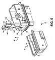
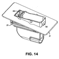
- the second plug 17 of the connector is in Fig. 5 partially exploded.
- the second plug 17 has a second plug housing 25, a drip protection cap 26 and a locking device 102.
- the drip protection cap 26 can be pushed onto the second connector housing 25 in the direction of the arrow 29. In this case, an outer periphery 30 of the second connector housing 25 and a Umgreifrand 31 of the drip protection cap 26 engage each other.
- the drip protection cap is secured to the connector housing 25 via a catch 196.
- the locking device 102 has an actuating projection 156, which facilitates the operation of the locking device by the user.
- the surfaces 158 provide in the locked state for blocking the latching hooks 131st
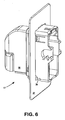
- the Fig. 6 Finally, shows the second connector 17 again in the held in the partition wall 37, ready for insertion position.
- the first connector 1 is pre-assembled. Referring to Fig. 4 In this case, the first pin receptacle 5 is inserted in the arrow direction 8 in sections into the second pin receptacle 6. In this state, the first and second pin receiving 6, 5 are inserted in the direction of arrow 9 in the interior of the first connector housing 2. Thereafter, a spout (not shown here) can be pushed over the connecting piece 7 in sections.
- the first connector 1 further includes mounting pins in the first and second pin recordings and laying a Zufuel horrs through the interior of the spout in the interior of the first connector housing 2 and connecting wires of the connecting cable with corresponding pins.
- the drip protection cap 26 is pushed onto the second connector housing 25 in the direction of arrow 29. Also in the second connector 17 pins are used and one or more feed lines are placed.
- connection can be made through the opening 39 of the partition wall 37 by means of the connector according to the invention.
- the connection in this embodiment is an electrical connection.
- the second plug 17 is guided in the direction of arrow 38 through the opening 39 of the partition wall 37.
- the execution takes place until the locking projections 131 are secured to the partition wall.
- the locking device 102 is inserted in the direction of 103 in the housing 25 and pushed down until a latching takes place in the latching opening 124 and is therefore secured over the surfaces 158 of the latching arm 152 against bending inwards, so that the second plug 17th now captive secured in the partition.
- the second plug 17 is now secured in its position relative to the partition wall 37. This can be a pre-assembly state in the automotive industry.
- first and second plug 1, 17 can take place.
- the first plug 1 is brought to the second plug 17 in the direction of arrow 150 and mated with the second plug 17.
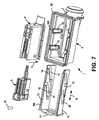
- the first connector 1 instead of the locking lever designed as a tensioning device 704 for tensioning the two connectors against each other.
- the pusher 704 is slidably received in the direction of arrow 10 in the first connector housing 2.
- the pusher 704 has an actuating surface 11 to which a displacement force for displacing the pusher can be applied.
- the pusher 704 has side members 12, 13. As in Fig. 7 are shown in the side members 12, 13 respectively upper guide rails 14 and lower guide rails 15 provided.
- the guide rails 14, 15 are guide recesses in this embodiment of the invention.
- an intended joining direction of the first plug 2 with the second plug 17 is indicated by an arrow 16.
- the direction 10 in which the pusher 704 is slidable in the first connector housing 2 is approximately transverse to the mating direction 16 of the first connector 1 with the second connector 17.
- the guide rails 14, 15 have reduction sections 18, 19 which are unidirectional run approximately transversely to the mating direction 16 and approximately transversely to the sliding direction 10.
- the guide rails 14, 15 end portions 20, 21 which extend parallel to the sliding direction 10.
- the guide rails 14, 15 cooperate with associated pin-like projections 33, 34 for clamping the two connectors against each other and to the partition wall.
- a seal 28 is further circumferentially mounted on the first connector housing 2.
- the seal 28 is sprayed onto the housing 2.
- the seal 28 is thus captively secured to the first connector housing 2, and the connection between the seal 28 and the first connector housing 2 is always sealed.
- the seal 28 may also be a separate part to the first connector housing 2.
- Fig. 8 the second plug 17 according to the present invention is shown in partially exploded view. Those elements which correspond to those according to the first embodiment are not mentioned separately again in the following.
- the second plug 17 has pin-like projections 33, 34, which are integrally formed on the plug housing 25.
- the pin-like projections 33, 34 are formed so that they can be engaged with the guide rails 14, 15 of the slider 704 of the first connector and thus constitute engagement means for the tensioning device 704 serving as a tensioning device.
- sealing projections 198 are further integrally formed on the second connector housing 25, which can form a sealing connection with the seals 163.
- An elastic spring arm 152 with a holding device 131 serves as with reference to FIG Fig. 10 is still clear, a fastening of the second plug 17 in the opening of the partition wall 37.
- a locking device 102 allows blocking of this elastic spring arm 152 for locking the second plug 17 in the partition by an inward bending of the spring arm 152 in the locked state is prevented.
- the locking device 102 according to this embodiment, as with reference to the FIGS. 15 and 16 more clearly, bearing projections 206 held in corresponding bearing recesses 208 on the second connector housing 25. Thereby, the locking device 102 can be moved between a locked and an unlocked position about a rotation axis 202. In the unlocked position, the locking device 102 is secured in the latching recess 210, in the locked position in the latching recess 212.
- Fig. 9 shows in a perspective view the plug-ready first connector. 1
- Fig. 10 the plug-in second connector 17 is shown, with the locking device 102 in the locked position, so that the second plug 17 in the Partition 37 is securely held. In this position, moreover, the edge 204 of the locking device 102 with the connector housing 25 in such a system that the pin tray released and thus plugging together the two connectors is possible.
- Fig. 11 shows a perspective, partially sectioned view of the connector according to the invention in the final assembled and mated condition.
- the sealing devices 28 and 163 ensure a complete sealing of the internal electrical connections against the ingress of moisture.
- the two plugs 1 and 17 are firmly clamped to the partition wall 37.
- the second plug 17 is pivoted about the lower edge in the direction 112, so that the projection 131 holds the second plug 17 in the partition wall 37.
- the locking device 102 can be tilted in the direction 113, so that on the one hand an inward pressing of the latching hook 131 is prevented, and on the other hand in the FIGS. 15 and 16 more clearly visible projections 214, 216 cooperate with the partition wall 37 to hold the second plug 17 in the opening of the partition wall 37.
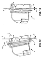
- the plug 17 is also in the in Fig. 13 shown pre-assembled position still displaceable by the distance 137 transversely to the mating direction.
- the pin tray 128 is in the in Fig. 13 shown position of the locking device 102 released, so that a mating can now take place.
- FIGS. 15 and 16 Two detailed views of the second connector for more detailed explanation of the operation of the locking device 102 are in the FIGS. 15 and 16 shown.
- Fig. 15 shows the unlocked state in which the locking device 102 is locked in the latching recess 210 that the pin tray 128 is blocked for mating the two plugs.
- the locking device is held by means of the bearing projections 206 in the bearing recesses 208 so that it is pivotable in the direction 113.
- the in Fig. 16 In the locked position shown, on the one hand, the movement of the latching hook 131 is blocked, and in addition the protrusions 214, 216 penetrating through the second connector housing directly secure the second plug 17 in the partition 37. Through the fixed retaining projection 132, the plug 17 is secured to the opposite end of the plug Housing 25 held in the partition 37.
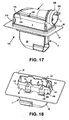
- FIG. 17 shows in a perspective view of a further advantageous embodiment of the connector according to the invention.
- a sliding device 704 for tensioning the two connectors 1, 2 against each other is also provided here.
- a recess 218 is provided on both sides of the first connector housing 2, which is a secure gripping the sliding device 704 for allows an operator.
- Locking recesses 220 and 224 secure via associated latching hooks 226 (see also FIG. 20 In particular, the latching hook 226 engages in the final assembled state in the latching recess 220 and is secured in the preassembled state by the latching recess 224.
- the socket 7 in the embodiment shown here has a resilient latching arm 230. Both the circumferential projection 228 as well as the locking arm 230 allow the mechanical fixation of a spout not shown here.
- FIG. 18 A perspective view of the second plug 17 FIG. 17 is in the FIG. 18 shown.
- the second plug 17 is positioned in the partition wall 37, but not yet finally fixed.
- the locking device 102 is still in the pre-locked position.
- the locking in the dividing wall 37 takes place here exclusively via the elastic spring arm 152 and the holding structure 131 formed thereon, as well as via the opposite holding structure 132.
- the locking device 102 holds as follows FIG. 19 is still clear, in the final latched state, the spring arm 152 in the locked position.
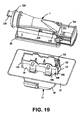
- FIG. 19 is the connector 100 off FIG. 17 shown before mating the first and second connectors 1, 17.
- the second plug 17 is firmly held in the partition wall 37 at this stage, and the locking device 102 holds the spring arm 152 in the position shown.
- the first plug 1 is in a plug-in position, in which the sliding device 704 is locked in a preassembled position by means of the latching openings 224.
- FIG. 20 shows the first connector 1 according to the in FIG. 17 shown embodiment in a too FIG. 7 analog representation.
- the explanations given with regard to the second embodiment also apply correspondingly to the explanations given in FIG FIG. 20 shown embodiment.
- the openings 72 and 73 provided with circumferential seals 163 and the functionality of the sliding device 704 correspond those of the first embodiment.
- the slider 704 has latching hooks 226 to be securely held in the first connector housing 2 both in a pre-engaged position and in the final assembled position.
- the first pin receptacle 5 and the second pin receptacle 6 have a slightly modified form.
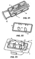
- FIG. 21 shows in a perspective view the plug-ready first connector 1 according to the in FIG. 20 shown embodiment.
- FIG. 22 the peripheral seal 28 for sealing against the partition wall 37 and the sealing devices 163 are shown detached from the connector.
- the four sealing devices 163 are made in one piece with the seal 28 by being connected to the seal 28 via webs 199.
- This embodiment offers the advantage of simplified manufacturability in a single operation both as a separately inserted seal assembly as well as molded onto the plug 1 seal. In the latter case, 163 no disturbing injection points must be provided on the fine structures of the sealing devices.
- this embodiment allows a secure seal in the region of the projections 33, 34th
- FIG. 23 shows the plug-ready second connector 17 according to the embodiment FIG. 19 , wherein the second plug 17 is mounted in the partition wall 37 and the seals 28 and 163 FIG. 21 to illustrate their position are also shown.
- the seal 28 and the sealing devices 163 are in turn made in one piece by the webs 199 make a connection.
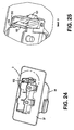
- FIGS. 24 and 25 is the embodiment of the locking device 102 according to the in FIG. 18 shown embodiment and in the unlocked position shown in detail.
- the functionality of the locking device 102 essentially corresponds to that with reference to FIGS FIGS. 15 and 16 explained principles.
- FIG. 26 shows the second plug 17 FIG. 19 in a partially exploded representation.
- the simplified design of the pivotable locking device 102 is important.
- the locking device 102 is configured here without the protrusions 214, 216 penetrating through the second connector housing. Apart from that, however, all the functional mechanisms set forth with reference to the preceding embodiments can also be applied to the present embodiment.
- the connector according to the invention can be achieved that on the one hand, the tightness is not affected by the cable, and that on the other hand, due to the axial seal on the female connector optimal sealing function to a partition, such as a body panel, is guaranteed.
- the pen tray is protected against dripping water and both the assembly and disassembly are simple and clear.
- the closing of the coupling causes in addition to the electrical contact also a defined D Diesspressung between plug and partition.
- the Kojiri safety can be ensured by a deep tub and a high guard bar.
Landscapes
- Connector Housings Or Holding Contact Members (AREA)
- Joining Of Building Structures In Genera (AREA)
- Finishing Walls (AREA)
Abstract
Description
Die vorliegende Erfindung bezieht sich auf eine Steckverbindung zum Herstellen wenigstens einer elektrischen Verbindung durch eine Öffnung einer Trennwand hindurch. Die Steckverbindung, die auch als Durchgangsstecker bezeichnet wird, weist einen ersten und einen zweiten Stecker auf, die zusammensteckbar sind und wenigstens einer der Stecker ist über eine die Öffnung umschließende Dichtung gegen die Trennwand abdichtbar. Insbesondere bezieht sich die vorliegende Erfindung auf eine Steckverbindung, bei der wenigstens einer der Stecker eine Spannvorrichtung aufweist, die mit dem anderen Stecker in Eingriff bringbar ist und mit welcher die beiden Stecker in ihrer Zusammensteckrichtung unter Einbeziehen der Trennwand dauerhaft spannbar sind. Die Erfindung bezieht sich weiterhin auf ein Montageverfahren zum Herstellen einer derartigen elektrischen Steckverbindung.The present invention relates to a connector for making at least one electrical connection through an opening of a partition. The connector, which is also referred to as a through-connector, has a first and a second connector which can be plugged together and at least one of the connectors can be sealed against the partition wall via a seal enclosing the opening. In particular, the present invention relates to a connector in which at least one of the plugs has a tensioning device which can be brought into engagement with the other plug and with which the two plugs are permanently tensioned in their mating direction by incorporating the partition wall. The invention further relates to a mounting method for producing such an electrical connector.
Bei einem bekannten gattungsgemäßen Steckverbinder, wie er beispielsweise in der veröffentlichten internationalen Patentanmeldung
Allerdings tritt bei dieser bekannten Spannvorrichtung das Problem auf, dass an den Verbindungsstellen zwischen der Spannvorrichtung und den Steckern Feuchtigkeit eindringen kann, die zum Ausfall der Steckverbindung führen kann.However, in this known tensioning device the problem arises that moisture can penetrate at the connection points between the tensioning device and the plugs, which can lead to failure of the plug connection.
Aus der
Die
Aus der
Aus der
Der Erfindung liegt daher die Aufgabe zugrunde, eine gattungsgemäße Steckverbindung der genannten Art dahingehend zu verbessern, dass die Dichtigkeit gegenüber der Umgebung und die Zuverlässigkeit der Verbindung erhöht werden können.The invention is therefore based on the object to improve a generic connector of the type mentioned in that the tightness against the environment and the reliability of the connection can be increased.
Gemäß der vorliegenden Erfindung wird diese Aufgabe durch eine Steckverbindung mit den Merkmalen des Patentanspruchs 1 gelöst.According to the present invention, this object is achieved by a plug connection with the features of
Vorteilhafte Weiterbildungen der vorliegenden Erfindung sind Gegenstand mehrerer Unteransprüche.Advantageous developments of the present invention are the subject of several subclaims.
Die vorliegende Erfindung beruht auf dem Grundgedanken, dass ein unerwünschtes Eindringen von Feuchtigkeit in den Innenraum des Steckverbinders dadurch vermieden werden kann, dass der Verbindungsbereich zwischen der Spannvorrichtung und dem mindestens einen Stecker mittels einer Dichtvorrichtung abgedichtet wird.The present invention is based on the basic idea that an undesirable penetration of moisture into the interior of the connector can be avoided by sealing the connection region between the clamping device and the at least one connector by means of a sealing device.
Gemäß einer vorteilhaften Ausführungsform weist die Spannvorrichtung wenigstens einen Betätigungsvorsprung auf, der zum Spannen der Stecker mit einer Aufnahme, die an einem der Stecker angeordnet ist, zusammenwirkt. Auf diese Art und Weise kann in sehr einfacher Art und Weise eine Übersetzung der beim Spannen aufgewendeten Kraft in eine Spannkraft erfolgen.According to an advantageous embodiment, the tensioning device has at least one actuating projection, which cooperates for tensioning the plug with a receptacle which is arranged on one of the plugs. In this way can be done in a very simple manner, a translation of the expended during clamping force in a clamping force.
Um den Bereich, den eine derartige Dichtvorrichtung abdichten muss, möglichst gering zu halten, kann die Spannvorrichtung einen Verriegelungshebel aufweisen, der zum Spannen der beiden Stecker um eine Drehachse, die etwa quer zu der Durchführrichtung durch die Trennwand verläuft, schwenkbar ist. Bei einer derartigen Anordnung genügt es, den Bereich, in welchem der Verriegelungshebel drehbar gelagert ist, abzudichten.In order to minimize the area that such a sealing device has to seal, the tensioning device can have a locking lever, which is pivotable for tensioning the two plugs about an axis of rotation which runs approximately transversely to the direction of passage through the dividing wall. In such an arrangement, it is sufficient to seal the area in which the locking lever is rotatably mounted.
Um eine besonders effektive Kraftübersetzung einer Schwenkbewegung in eine Spannkraft zum Spannen der beiden Stecker zu erzielen, kann als Betätigungsvorsprung jeweils mindestens ein Zahn mit evolventischen Zahnflanken an den Lagervorsprüngen angeordnet sein.In order to achieve a particularly effective force transmission of a pivoting movement into a clamping force for tensioning the two plugs, at least one tooth with involute tooth flanks can be arranged on the bearing projections as the actuating projection.
Die Spannvorrichtung kann einen Verriegelungshebel mit einem Basisbereich sowie zwei Schenkelbereichen aufweisen. An den Schenkelbereichen sind Lagervorsprünge angeformt, die in entsprechenden Lagerausnehmungen des einen Steckers drehbar gelagert sind. Auf diese Weise kann in besonders einfacher Weise realisiert werden, dass der Verriegelungshebel zum Spannen der Stecker um eine Drehachse, die etwa quer zu der Durchführrichtung durch die Trennwand verläuft, schwenkbar ist. Die Dichtvorrichtung kann dann an den Lagervorsprüngen angeordnet werden, beispielsweise in Form eines O-Rings, oder sie wird alternativ direkt an die Lagervorsprünge angespritzt.The tensioning device may comprise a locking lever having a base portion and two leg portions. At the leg portions bearing projections are formed, which are rotatably mounted in corresponding bearing recesses of a plug. In this way it can be realized in a particularly simple manner that the locking lever for clamping the connector about an axis of rotation, which extends approximately transversely to the direction of passage through the partition, is pivotable. The sealing device can then be arranged on the bearing projections, for example in the form of an O-ring, or it is alternatively injection-molded directly onto the bearing projections.
Eine besonders kostengünstige und einfache Realisierung der erfindungsgemäßen Dichtvorrichtung ist gegeben, wenn die Dichtvorrichtung durch einen elastischen O-Ring gebildet ist.A particularly cost-effective and simple realization of the sealing device according to the invention is given when the sealing device is formed by an elastic O-ring.
Die Dichtung gegenüber der Trennwand muss umlaufend um die Öffnung in der Trennwand angebracht sein. Gemäß einer vorteilhaften Ausführungsform kann die Dichtung auf die äußere Peripherie des Steckers aufgespritzt werden, so dass die Dichtung unverlierbar an dem Steckergehäuse angebracht ist. Darüber hinaus ist die Verbindung zwischen der Dichtung und dem Stecker, an dem sie angespritzt ist, stets vollständig dicht. Allerdings kann diese Dichtung auch ein separates Teil sein, das sowohl mit dem Stecker wie auch mit der Trennwand in Anlage bringbar ist.The seal opposite the dividing wall must be mounted circumferentially around the opening in the dividing wall. According to an advantageous embodiment, the seal can be sprayed onto the outer periphery of the plug, so that the seal is captively attached to the connector housing. In addition, the connection between the seal and the plug on which it is molded, always completely tight. However, this seal can also be a separate part that can be brought into contact with both the plug and the partition.
Um ein unbeabsichtigtes Lösen der Spannvorrichtung zu verhindern, kann eine separate Sicherungsvorrichtung, die auch als Connector Position Assurance (CPA) bezeichnet wird, zum Arretieren der Spannvorrichtung in einem endmontierten Zustand vorgesehen sein.To prevent unintentional release of the tensioning device, a separate locking device, also referred to as connector position assurance (CPA), may be provided for locking the tensioning device in a final assembled condition.
Auf eine besonders raumsparende Art und Weise lösbar wird die Sicherungsvorrichtung, wenn sie in einer Richtung quer zu der Durchführrichtung durch die Trennwand verschieblich ist.In a particularly space-saving manner, the securing device is released when it is displaceable in a direction transverse to the direction of passage through the partition wall.
Eine Rastnase, die zum Verrasten der Spannvorrichtung an der Sicherungsvorrichtung vorgesehen ist, stellt eine besonders effektive und leicht realisierbare Möglichkeit der Arretierung dar.A locking lug, which is provided for locking the tensioning device on the securing device, represents a particularly effective and easily realizable possibility of locking.
Alternativ zu dem schwenkbaren Verriegelungshebel kann gemäß der vorliegenden Erfindung eine entsprechend abgedichtete Schiebespannvorrichtung verwendet werden, was beispielsweise dann sinnvoll ist, wenn der zur Verfügung stehende Bauraum ein Schwenken des Verriegelungshebels bei der Montage nicht zulässt. Dabei kann die Spannvorrichtung eine Schiebevorrichtung mit wenigstens einer Über- oder Untersetzungsanordnung sein. Diese ermöglicht ein Umwandeln einer aufgebrachten Schiebekraft oder -bewegung in eine größere oder kleinere Spannkraft oder -bewegung.As an alternative to the pivotable locking lever can be used according to the present invention, a correspondingly sealed sliding clamping device, which is useful, for example, if the available space does not allow pivoting of the locking lever during assembly. In this case, the tensioning device may be a sliding device with at least one transmission or reduction arrangement. This allows converting an applied pushing force or movement into a greater or lesser clamping force or movement.
Besonders vorteilhaft kann die Spannvorrichtung eine Schiebevorrichtung sein, die zum Spannen der Stecker in eine Richtung etwa quer zur Durchführrichtung durch die Trennwand verschiebbar ist. Dadurch ist eine besonders einfache Spannvorrichtung an der Steckverbindung möglich, das Spannen kann sehr schnell und einfach ausgeführt werden und der benötigte Bauraum kann gering gehalten werden.Particularly advantageously, the tensioning device may be a sliding device, which is displaceable in a direction approximately transverse to the direction of passage through the partition wall for tensioning the plug. As a result, a particularly simple clamping device on the connector is possible, the clamping can be performed very quickly and easily and the required space can be kept low.
In einer weiteren vorteilhaften Ausführungsform der Erfindung kann die Spannvorrichtung wenigstens eine Führungsschiene aufweisen, welche teilweise in einer Ebene längs zur Zusammensteckrichtung und etwa quer zur Zusammensteckrichtung verläuft. Damit ist eine Schiebekraft oder -bewegung in eine Spannkraft oder -bewegung umwandelbar.In a further advantageous embodiment of the invention, the tensioning device may comprise at least one guide rail, which extends partially in a plane along the Zusammensteckrichtung and approximately transversely to the mating direction. This is a sliding force or movement in a clamping force or movement convertible.
Sieht man eine Dichtvorrichtung an einer Öffnung eines ersten Steckergehäuses, durch welche ein Eingriffselement der Spannvorrichtung hindurchtaucht, vor, so kann eine als Schiebevorrichtung ausgebildete Spannvorrichtung gegenüber eindringender Feuchtigkeit besonders effektiv abgedichtet werden. Eine derartige Dichtung kann beispielsweise angespritzt sein und zur Verbesserung der Dichtigkeit auch kompliziertere Querschnitte, z. B. solche mit mindestens einer Dichtlippe, aufweisen.If one observes a sealing device at an opening of a first connector housing, through which an engagement element of the clamping device penetrates, then a clamping device designed as a sliding device can be sealed particularly effectively against penetrating moisture. Such a seal can for example be injected and to improve the tightness and more complicated cross-sections, z. B. having at least one sealing lip.
Eine besonders sichere und mit wenig Kraftaufwand realisierbare Dichtung kann erreicht werden, wenn an einem zweiten Steckergehäuse mindestens ein Dichtvorsprung angeformt ist, der zum Abdichten der Steckverbindung mit der Dichtvorrichtung zusammenwirkt.A particularly secure and realized with little effort seal can be achieved if at least one sealing projection is formed on a second connector housing, which cooperates for sealing the connector with the sealing device.
Dadurch, dass weiterhin eine Verriegelungsvorrichtung vorgesehen ist, die zwischen einer verriegelten Stellung, in welcher der zweite Stecker an der Trennwand fixiert ist, und einer unverriegelten Stellung bewegbar ist, kann eine besonders sichere Fixierung des zweiten Steckers an der Trennwand erreicht werden. Eine derartige Verriegelungsvorrichtung, die auch als weitere Connector Position Assurance (CPA) bezeichnet werden kann, kann so ausgeführt werden, dass auch eine Entriegelung möglich ist und im Falle einer Reparatur der zweite Stecker leicht aus der Trennwand entfernt werden kann. Andererseits kann, wenn beim Stecken des ersten Steckers größer Kräfte aufgewendet werden müssen, sichergestellt werden, dass der zweite Stecker nicht unbeabsichtigt von der Trennwand gelöst wird. Insbesondere, wenn dieser zweite Stecker in einem Karosserieblech gehalten ist, dessen Rückseite zum Zeitpunkt des Zusammensteckens nicht mehr ohne weiteres zugänglich ist, wie dies beispielsweise bei einer Autotür der Fall ist, kann mit der erfindungsgemäßen Lösung vermieden werden, dass der zweite Stecker nicht mehr ordnungsgemäß kontaktiert werden kann.Characterized in that further a locking device is provided, which is movable between a locked position in which the second connector is fixed to the partition, and an unlocked position, a particularly secure fixation of the second connector can be achieved on the partition. Such a locking device, which can also be referred to as a further connector position assurance (CPA), can be designed so that unlocking is also possible and, in the event of repair, the second connector can be easily removed from the partition wall. On the other hand, if greater forces must be expended when plugging in the first plug, it can be ensured that the second plug is not unintentionally released from the partition wall. In particular, if this second plug is held in a body panel whose rear side is no longer readily accessible at the time of mating, as is the case for example in a car door, can be avoided with the inventive solution that the second plug no longer properly can be contacted.
Dadurch, dass die Verriegelungsvorrichtung in der unverriegelten Stellung mechanisch fixiert ist, kann eine definierte Lage der Verriegelungsvorrichtung im vormontierten Zustand sichergestellt werden.Characterized in that the locking device is mechanically fixed in the unlocked position, a defined position of the locking device can be ensured in the preassembled state.
Weiterhin kann an der Verriegelungsvorrichtung mindestens eine Rastvorrichtung angeordnet sein, um die Verriegelungsvorrichtung im Zusammenwirken mit einer zugehörigen Rastöffnung in der verriegelten Stellung zu sichern. Dies ist besonders bei Anwendungen im Kraftfahrzeugbereich von Bedeutung, weil hier starke mechanische und thermische Beanspruchungen während des Betriebs auftreten.Furthermore, at least one latching device can be arranged on the locking device in order to secure the locking device in cooperation with an associated latching opening in the locked position. This is particularly important in applications in the automotive sector, because strong mechanical and thermal stresses occur during operation.
Damit sich die Verriegelungsvorrichtung nicht unbeabsichtigt aus der unverriegelten Stellung bewegen kann, kann die mindestens eine Rastvorrichtung in der unverriegelten Stellung mit einer weiteren zugehörigen Rastöffnung zusammenwirken, um die Verriegelungsvorrichtung auch in dieser Stellung zu fixieren. Zweckmäßigerweise ist diese Rastverbindung von außen (zumindest für ein geeignetes Werkzeug) zugänglich, so dass sie im Falle eines gewünschten Ausbaus lösbar ist.Thus, the locking device can not move unintentionally from the unlocked position, the at least one locking device in the unlocked position cooperate with another associated locking opening to fix the locking device in this position. Conveniently, this locking connection from the outside (at least for a suitable tool) accessible so that it is solvable in the case of a desired expansion.
Die Verriegelungsvorrichtung kann im einfachsten Fall mit Bezug auf den zweiten Stecker in Zusammensteckrichtung der beiden Stecker verschieblich sein. Allerdings hat diese Lösung den Nachteil, dass nicht sichergestellt werden kann, dass die beiden Stecker nur dann steckbar sind, wenn die Verriegelungsvorrichtung sich ordnungsgemäß in ihrer verriegelten Stellung befindet. Um auf besonders einfache Weise sicherzustellen, dass die beiden Stecker nur dann steckbar sind, wenn der zweite Stecker sich in seiner Endstellung in der Öffnung der Trennwand befindet und die Verriegelungsvorrichtung ordnungsgemäß verriegelt ist, kann die Verriegelungsvorrichtung mittels einer scharnierartigen Verbindung an dem zweiten Steckergehäuse gelagert sein und zwischen der verriegelten und der unverriegelten Stellung durch eine Schwenkbewegung um eine Achse, die etwa quer zur Durchführrichtung durch die Trennwand verläuft, bewegbar sein.The locking device may be displaceable in the simplest case with respect to the second connector in the direction of joining the two connectors. However, this solution has the disadvantage that it can not be ensured that the two plugs are pluggable only when the locking device is properly in its locked position. In order to ensure in a particularly simple manner that the two plugs are pluggable only when the second plug is in its end position in the opening of the partition and the locking device is properly locked, the locking device may be mounted by means of a hinge-like connection to the second connector housing and between the locked and the unlocked position by a pivoting movement about an axis which extends approximately transversely to the direction of passage through the partition to be movable.
Bei einer derartigen Ausführungsform kann dann beispielsweise ein der Drehachse gegenüberliegender Randbereich im unverriegelten Zustand so in dem zweiten Steckergehäuse angeordnet sein, dass die beiden Stecker nicht zusammensteckbar sind.In such an embodiment, for example, an edge region lying opposite the axis of rotation in the unlocked state can thus be arranged in the second connector housing such that the two connectors can not be plugged together.
Selbstverständlich kann die im Zusammenhang mit der vorliegenden Spannvorrichtung vorgeschlagene Verriegelungsvorrichtung auch für andere Steckverbindungen eingesetzt werden.Of course, the proposed in connection with the present clamping device locking device can also be used for other connectors.
Anhand der in den beiliegenden Zeichnungen dargestellten Ausgestaltungen wird die Erfindung im Folgenden näher erläutert. Ähnliche oder korrespondierende Einzelheiten der erfindungsgemäßen Steckverbindung sind in den Figuren mit denselben Bezugszeichen versehen. Es zeigen:
- Fig. 1
- eine perspektivische, teilweise geöffnete Darstellung eines in einer Öffnung einer Trennwand montierten Steckverbinders;
- Fig. 2
- eine gegenüber der Darstellung aus
Fig.1 gedrehte perspektivische Darstellung der Steckverbindung; - Fig. 3
- eine perspektivische Darstellung der Steckverbindung aus
Fig.1 , bei der eine der beiden Stecker in der Öffnung der Trennwand gehalten ist und der andere Stecker im montagebereiten Zustand vor dem Zusammenstecken positioniert ist; - Fig. 4
- eine perspektivische, teilweise explodierte Darstellung des ersten Steckers gemäß
Fig. 1 ; - Fig. 5
- eine perspektivische, teilweise explodierte Darstellung des zweiten Steckers gemäß
Fig. 1 ; - Fig. 6
- eine perspektivische Darstellung des in der Trennwand gehaltenen zweiten Steckers gemäß
Fig. 1 ; - Fig. 7
- eine perspektivische, teilweise explodierte Darstellung eines ersten Steckers gemäß der vorliegenden Erfindung;
- Fig. 8
- eine perspektivische, teilweise explodierte Darstellung eines zweiten Steckers gemäß der vorliegenden Erfindung;
- Fig. 9
- eine perspektivische Darstellung des ersten Steckers aus
Fig. 7 im montagebereiten Zustand; - Fig. 10
- eine perspektivische Darstellung des in der Trennwand gehaltenen zweiten Steckers gemäß der vorliegenden Erfindung;
- Fig. 11
- eine perspektivische, teilweise geöffnete Darstellung des in der Öffnung einer Trennwand montierten Steckverbinders gemäß der vorliegenden Erfindung;
- Fig. 12
- eine teilweise geschnittene Darstellung des zweiten Steckers gemäß einer weiteren vorteilhaften Ausführungsform während der Montage in der Trennwand;
- Fig. 13
- eine teilweise geschnittene Darstellung des zweiten Steckers gemäß
Fig. 12 nach der Montage in der Trennwand; - Fig. 14
- eine perspektivische Ansicht des zweiten Steckers aus
Fig. 12 ; - Fig. 15
- eine perspektivische Detailansicht des zweiten Steckers gemäß
Fig. 12 , wobei die Verriegelungsvorrichtung im vormontierten Zustand dargestellt ist; - Fig. 16
- eine perspektivische, teilweise geöffnete Detailansicht des zweiten Steckers gemäß
Fig. 12 , wobei die Verriegelungsvorrichtung sich im verriegelten Zustand befindet; - Fig. 17
- eine perspektivische Darstellung eines in der Öffnung einer Trennwand montierten Steckverbinders gemäß einer weiteren vorteilhaften Ausführungsform;
- Fig. 18
- eine perspektivische Darstellung des zweiten Steckers aus
Fig. 17 ; - Fig. 19
- eine perspektivische Darstellung des Steckverbinders aus
Fig. 17 vor dem Zusammenstecken von erstem und zweitem Stecker; - Fig. 20
- eine perspektivische, teilweise explodierte Darstellung des ersten Steckers aus
Fig. 17 ; - Fig. 21
- eine perspektivische Darstellung des ersten Steckers aus
Fig. 19 im montagebereiten Zustand; - Fig. 22
- eine perspektivische Darstellung einer einteiligen Ausführungsform der Dichtungen aus
Fig. 21 ; - Fig. 23
- eine perspektivische Darstellung des in der Trennwand gehaltenen zweiten Steckers gemäß
Fig. 19 mit Dichtungen; - Fig. 24
- eine perspektivische, teilweise geöffnete Darstellung des zweiten Steckers gemäß
Fig. 19 mit entriegelter Verriegelungsvorrichtung; - Fig. 25
- ein Detail D aus
Fig. 24 ; - Fig. 26
- eine perspektivische, teilweise explodierte Darstellung des zweiten Steckers aus
Fig. 19 .
- Fig. 1
- a perspective, partially open view of a mounted in an opening of a partition connector;
- Fig. 2
- one opposite to the presentation
Fig.1 rotated perspective view of the connector; - Fig. 3
- a perspective view of the connector
Fig.1 in which one of the two plugs is held in the opening of the partition wall and the other plug is positioned in the ready-to-mount state prior to mating; - Fig. 4
- a perspective, partially exploded view of the first connector according to
Fig. 1 ; - Fig. 5
- a perspective, partially exploded view of the second connector according to
Fig. 1 ; - Fig. 6
- a perspective view of the second plug held in the partition according to
Fig. 1 ; - Fig. 7
- a perspective, partially exploded view of a first connector according to the present invention;
- Fig. 8
- a perspective, partially exploded view of a second connector according to the present invention;
- Fig. 9
- a perspective view of the first connector
Fig. 7 ready for installation; - Fig. 10
- a perspective view of the held in the partition second connector according to the present invention;
- Fig. 11
- a perspective, partially open view of the mounted in the opening of a partition connector according to the present invention;
- Fig. 12
- a partially sectioned view of the second connector according to a further advantageous embodiment during assembly in the partition wall;
- Fig. 13
- a partially sectioned view of the second connector according to
Fig. 12 after installation in the partition; - Fig. 14
- a perspective view of the second connector
Fig. 12 ; - Fig. 15
- a perspective detail view of the second connector according to
Fig. 12 wherein the locking device is shown in the preassembled state; - Fig. 16
- a perspective, partially open detail view of the second connector according to
Fig. 12 wherein the locking device is in the locked state; - Fig. 17
- a perspective view of a mounted in the opening of a partition connector according to a further advantageous embodiment;
- Fig. 18
- a perspective view of the second connector
Fig. 17 ; - Fig. 19
- a perspective view of the connector
Fig. 17 before mating the first and second plugs; - Fig. 20
- a perspective, partially exploded view of the first connector
Fig. 17 ; - Fig. 21
- a perspective view of the first connector
Fig. 19 ready for installation; - Fig. 22
- a perspective view of a one-piece embodiment of the seals
Fig. 21 ; - Fig. 23
- a perspective view of the second plug held in the partition according to
Fig. 19 with seals; - Fig. 24
- a perspective, partially open view of the second connector according to
Fig. 19 with unlocked locking device; - Fig. 25
- a detail D off
Fig. 24 ; - Fig. 26
- a perspective, partially exploded view of the second connector
Fig. 19 ,
Eine Steckverbindung 100 weist mit Bezug auf
Wie in
Um ein Eindringen von Feuchtigkeit ins Innere des Steckers an der Verbindungsstelle zwischen dem ersten Steckergehäuse 2 und dem Verriegelungshebel 160 zu verhindern, weist der erste Stecker 1 eine Dichtvorrichtung 162 auf. Diese Dichtvorrichtung wird in der gezeigten Anordnung durch einen einfachen O-Ring realisiert. Selbstverständlich können aber auch andere Möglichkeiten zur Herstellung der Dichtvorrichtung genützt werden, wie beispielsweise angespritzte Dichtungen oder aufwendiger geformte Dichtungen, die z. B. Dichtlippen aufweisen.In order to prevent ingress of moisture into the interior of the plug at the connection point between the
Wie mit Bezug auf
Zur Verdeutlichung des Aufbaus des Verriegelungshebels 160 ist die Steckverbindung 100 in der
In
Um zu verhindern, dass der zweite Stecker 17 bei mechanischer Belastung während der Montage aus der Trennwand herausfallen kann, ist weiterhin eine Verriegelungsvorrichtung 102 vorgesehen, deren Funktionsweise darin besteht, im verriegelten Zustand ein Auslenken des Rastarms 152 nach innen zu blockieren, so dass der Stecker 17 nicht mehr aus der Öffnung herausfallen kann. Der federelastische Rastarm 152 ist dabei in der gezeigten Ausführungsform einstückig an das Kunststoffgehäuse des zweiten Steckers angeformt.In order to prevent the
Wie mit Bezug auf
Eine Tropfschutzkappe 26 deckt den zweiten Stecker 17 ab und schützt so vor dem Eindringen von Tropfwasser.A
Der erste Stecker 1 ist hier mit nach oben geschwenktem Verriegelungshebel 160 abgebildet. Die Sicherungsvorrichtung 170, die an dem Gehäuse 2 verschieblich gelagert ist, befindet sich in der gezeigten Darstellung in einer Position, in der beim späteren Schwenken des Verriegelungshebels 160 ein Verrasten mit der Rastnase 172 ermöglicht wird. Nach dem Schwenken des Verriegelungshebels 160 um die angedeutet dargestellt Drehachse 180 kann die Sicherungsvorrichtung 170 in Richtung 182 geschoben werden, wodurch die Rastnase 172 mit dem Vorsprung 184 an dem Verriegelungshebel 160 in Eingriff kommt und diesen sicher in seiner verriegelten Position hält. Ein Betätigungsvorsprung 186 erleichtert das Verschieben der Sicherungsvorrichtung 170. Um eine sichere Führung zu gewährleisten, wird die Sicherungsvorrichtung weiterhin in entsprechenden Nuten an dem Gehäuse 2 verschieblich gehalten. Schließlich ist an der Sicherungsvorrichtung 170 eine Sicherungslasche angeformt, die ein Verschieben der Sicherungsvorrichtung in Richtung 182 so lange verhindert, bis sie durch den heruntergeklappten Verriegelungshebel 160 an das Gehäuse 2 gedrückt wird und erlaubt, dass die Sicherungslasche 188 in die Nut 190 verschieblich ist.The
Über die Lagervorsprünge 164 ist jeweils als Dichtvorrichtung ein O-Ring 162 geschoben. Dieser O-Ring verhindert ein Eindringen von Feuchtigkeit durch die Lageröffnung 168 ins Innere des Steckergehäuses 2. Gegenüber der Trennwand ist das Steckergehäuse im montierten Zustand über die Dichtung 28 gedichtet. Diese Dichtung kann dabei entweder angespritzt oder als vorgefertigtes Teil, beispielsweise aus Silikonkautschuk, hergestellt und an dem Steckergehäuse 2 montiert sein. Der Verriegelungshebel 160 weist eine im Wesentlichen U-förmige Gestalt mit zwei Schenkeln, an denen die Lagervorsprünge 164 angeformt sind, und einer Basis, die mit der Sicherungsvorrichtung 170 in Eingriff kommt, auf. Dadurch, dass der Verriegelungshebel 160 das Gehäuse 2 teilweise umgibt, kann eine möglichst platzsparende Anordnung realisiert werden.About the bearing
An dem Lagervorsprung 164 ist jeweils als Betätigungselement 178 ein Teil eines Zahnrades ausgebildet, das mit entsprechenden Eingriffselementen 176 an dem zweiten Steckergehäuse 25 in Eingriff kommt. In vorteilhafter Weise ist das Betätigungselement 178 als Teil einer evolventen Verzahnung ausgebildet und die Zahnflanke 194, welche im endgültig montierten Zustand die gesamte Kraft halten muss, ist an das Vollmaterial des Lagervorsprungs 164 angeformt, um eine bessere Kraftaufnahme und Langzeitstabilität zu ermöglichen.On the bearing
Der zweite Stecker 17 des Steckverbinders ist in
Die Tropfschutzkappe 26 ist in Pfeilrichtung 29 auf das zweite Steckergehäuse 25 aufschiebbar. Dabei kommen eine äußere Peripherie 30 des zweiten Steckergehäuses 25 und ein Umgreifrand 31 der Tropfschutzkappe 26 miteinander in Eingriff.The
Im montierten Zustand ist die Tropfschutzkappe über eine Verrastung 196 an dem Steckergehäuse 25 gesichert.In the assembled state, the drip protection cap is secured to the
Wie aus der Darstellung der
Die
Nachfolgend wird die Montage der in den
Zunächst wird der erste Stecker 1 vormontiert. Bezugnehmend auf
Unabhängig davon erfolgt die Montage des zweiten Steckers 17. Dabei wird insbesondere die Tropfschutzkappe 26 auf das zweite Steckergehäuse 25 in Pfeilrichtung 29 aufgeschoben. Auch in den zweiten Stecker 17 werden Pins eingesetzt und eine oder mehrere Zuführleitungen werden gelegt.Regardless of the assembly of the
Nun kann das Herstellen einer Verbindung durch die Öffnung 39 der Trennwand 37 hindurch mit Hilfe der erfindungsgemäßen Steckverbindung erfolgen. Dabei ist die Verbindung in dieser Ausführungsform eine elektrische Verbindung.Now, the connection can be made through the
Mit Bezug auf
Der zweite Stecker 17 ist nun in seiner Lage relativ zu der Trennwand 37 gesichert. Dies kann im Automobilbau ein Vormontagezustand sein.The
Nun kann das Zusammenstecken von erstem und zweitem Stecker 1, 17 erfolgen. Ausgehend von der in
Dann wird auf die Betätigungsfläche 11 des Verriegelungshebels 116 eine Kraft aufgebracht, so dass der Verriegelungshebel 116 um die Achse 180 geschwenkt wird und dabei die ausgeübte Kraft mittels der Zahnrad/Zahnstangenanordnung 178, 176 in eine Spannbewegung übersetzt wird. Dadurch wird zunehmend Spannung aufgebaut, solange bis das Betätigungselement 178 seine Endlage in dem Eingriffselement 176 eingenommen hat. Weiterhin rastet der Rasthaken 172 mit der Rastöffnung 174 ein. Im nächsten Schritt wird die Sicherungsvorrichtung 170 in Richtung 182 verschoben (siehe
Eine vorteilhafte Ausführungsform der erfindungsgemäßen Steckverbindung soll nunmehr mit Bezug auf die
Wie aus
Die Schiebevorrichtung 704 weist Seitenelemente 12, 13 auf. Wie in
In der
Wie mit Bezug auf
Erfindungsgemäß sind korrespondierend zu den stiftartigen Vorsprüngen 33, 34 Öffnungen 72, 73, durch welche die stiftartigen Vorsprünge 33, 34 hindurchtauchen, um mit der Schiebevorrichtung 704 zusammenzuwirken, mit umlaufenden Dichtungen 163 versehen, um diesen Verbindungsbereich gegen ein Eindringen von Feuchte ins Steckerinnere abzudichten.According to the invention, corresponding to the pin-
An dem ersten Steckergehäuse 2 ist weiterhin umlaufend eine Dichtung 28 angebracht. In der in
Das oben Gesagte gilt ebenso für die Dichtungen 163, die der gezeigten Ausführungsform an dem ersten Steckergehäuse ebenfalls angespritzt sind.The above also applies to the
In
Erfindungsgemäß weist der zweite Stecker 17 stiftartige Vorsprünge 33, 34 auf, die einstückig an dem Steckergehäuse 25 ausgeformt sind. Die stiftartigen Vorsprünge 33, 34 sind so ausgebildet, dass sie mit den Führungsschienen 14, 15 der Schiebevorrichtung 704 des ersten Steckers in Eingriff gebracht werden können und somit Eingriffsmittel für die als Spannvorrichtung dienende Schiebevorrichtung 704 darstellen.According to the invention, the
Zum Abdichten der Öffnungen 72, 73 mit Hilfe der Dichtungen 163 sind an dem zweiten Steckergehäuse 25 weiterhin Dichtvorsprünge 198 angeformt, die mit den Dichtungen 163 eine dichtende Verbindung eingehen können.For sealing the
Ein elastischer Federarm 152 mit einer Haltevorrichtung 131 dient, wie mit Bezug auf
Dabei weist die Verriegelungsvorrichtung 102 gemäß dieser Ausführungsform, wie mit Bezug auf die
In
Mit Bezug auf die
Es befindet sich, wie in der teilweise geöffneten Darstellung der
Nach dem Einhängen wird der zweite Stecker 17 um die untere Kante herum in Richtung 112 geschwenkt, so dass auch der Vorsprung 131 den zweiten Stecker 17 in der Trennwand 37 hält. Nun kann die Verriegelungsvorrichtung 102 in Richtung 113 gekippt werden, so dass einerseits ein Nach-Innen-Drücken des Rasthakens 131 verhindert wird, und zum anderen die in den
In der gezeigten Ausführungsform ist der Stecker 17 auch in der in
In perspektivischer Darstellung ist der Montageschritt, der in
Zwei Detailansichten des zweiten Steckers zur genaueren Erläuterung der Funktionsweise der Verriegelungsvorrichtung 102 sind in den
Zusätzlich zu dem im Zusammenhang mit der ersten Ausführungsform gezeigten umlaufenden Rastvorsprung 228 weist der Stutzen 7 in der hier gezeigten Ausführungsform einen federnden Rastarm 230 auf. Sowohl der umlaufende Vorsprung 228 wie auch der Rastarm 230 ermöglichen die mechanische Fixierung einer hier nicht näher dargestellten Tülle.In addition to the
Eine perspektivische Darstellung des zweiten Steckers 17 aus
In
In
Mit Bezug auf die
Mit Hilfe der erfindungsgemäßen Steckverbindung kann erreicht werden, dass zum einen die Dichtigkeit durch den Kabelzug nicht beeinflusst wird, und dass zum anderen aufgrund der Axialdichtung am Buchsenstecker eine optimale Dichtfunktion zu einer Trennwand, beispielsweise einem Karosserieblech, gewährleistet ist. Die Stiftwanne ist gegenüber Tropfwasser geschützt und sowohl die Montage wie auch die Demontage sind einfach und übersichtlich. Das Schließen der Kupplung bewirkt neben der elektrischen Kontaktierung auch eine definierte Dichtigkeitspressung zwischen Stecker und Trennwand. Schließlich kann durch eine tiefe Wanne sowie einen hohen Schutzsteg die Kojiri-Sicherheit gewährleistet werden.With the help of the connector according to the invention can be achieved that on the one hand, the tightness is not affected by the cable, and that on the other hand, due to the axial seal on the female connector optimal sealing function to a partition, such as a body panel, is guaranteed. The pen tray is protected against dripping water and both the assembly and disassembly are simple and clear. The closing of the coupling causes in addition to the electrical contact also a defined Dichtigkeitspressung between plug and partition. Finally, the Kojiri safety can be ensured by a deep tub and a high guard bar.
Claims (12)
- A plug connection for bringing about at least one connection through an opening (39) in a partition (37), the plug connection comprising a first and a second connector (1, 17), which may be mated together, and at least one of the connectors (1, 17) being sealable relative to the partition (37) by means of a seal (28) surrounding the opening (39), and,
at least one of the connectors (1, 17) comprising a clamping device, which may be brought into engagement with the other connector (17, 1) and with which the connectors (1, 17) may be clamped permanently in their mating direction (16) with inclusion of the partition (37),
the clamping device comprising at least one sealing device (162, 163) for sealing a connection area between the clamping device and the at least one connector (1, 17),
characterised in that
the clamping device comprises a sliding device (704) with at least one step-up or step-down arrangement (18, 19) and the at least one sealing device (163) is formed at an opening in a first connector housing (2) through which passes an engaging element of the clamping device. - A plug connection according to claim 1, characterised in that the clamping device comprises a sliding device (704), which may be slid in a direction approximately perpendicular to the passage direction (38) through the partition to clamp the connectors (1, 17).
- A plug connection according to claim 1 or claim 2, characterised in that the clamping device comprises at least one guide rail (18, 19), which extends at least in part in a plane along the mating direction (16) and roughly perpendicular to the mating direction (16).
- A plug connection according to any one of claims 1 to 3, characterised in that the sealing device (163) comprises at least one sealing lip.
- A plug connection according to any one of claims 1 to 4, characterised in that at least one sealing projection (198) is formed on a second connector housing (25), which sealing projection (198) cooperates with the sealing device (163) to seal the plug connection.
- A plug connection according to at least one of the preceding claims, characterised in that the seal (28) is injection-moulded onto the connector (1, 17).
- A plug connection according to at least one of the preceding claims, characterised in that the second connector (17) comprises a locking device (102), which is movable between a locked position, in which the second connector (17) is secured to the partition (37), and an unlocked position.
- A plug connection according to claim 7, characterised in that the locking device (102) is displaceable in relation to the second connector (17) in the mating direction of the two connectors (1, 17).
- A plug connection according to claim 7 or claim 8, characterised in that at least one latching device (110) is arranged on the locking device (102), in order to secure the locking device (102) in the locked position in cooperation with an associated latching opening (124).
- A plug connection according to claim 9, characterised in that the at least one latching device (110) cooperates in the unlocked position with a further associated latching opening (126), in order to hold the locking device (102) in place.
- A plug connection according to claim 7, characterised in that the locking device (102) is mounted on the second connector housing (25) by means of a hinge-like connection (200) and is movable between the locked and the unlocked position by a swivelling movement about an axis which extends approximately perpendicularly to the passage direction (38) through the partition (37).
- A plug connection according to at least one of the preceding claims, characterised in that the seal (28) and the sealing device (162, 163) are of one piece construction.
Priority Applications (1)
| Application Number | Priority Date | Filing Date | Title |
|---|---|---|---|
| PL05716340T PL1745528T3 (en) | 2004-04-07 | 2005-03-23 | Sealed plug-in connection that runs through a dividing wall and corresponding mounting method |
Applications Claiming Priority (2)
| Application Number | Priority Date | Filing Date | Title |
|---|---|---|---|
| DE102004017275A DE102004017275A1 (en) | 2004-04-07 | 2004-04-07 | Sealed plug-in connection through a partition and mounting method |
| PCT/EP2005/003122 WO2005101583A1 (en) | 2004-04-07 | 2005-03-23 | Sealed plug-in connection that runs through a dividing wall and corresponding mounting method |
Publications (2)
| Publication Number | Publication Date |
|---|---|
| EP1745528A1 EP1745528A1 (en) | 2007-01-24 |
| EP1745528B1 true EP1745528B1 (en) | 2008-05-21 |
Family
ID=34962682
Family Applications (1)
| Application Number | Title | Priority Date | Filing Date |
|---|---|---|---|
| EP05716340A Expired - Lifetime EP1745528B1 (en) | 2004-04-07 | 2005-03-23 | Sealed plug-in connection that runs through a dividing wall and corresponding mounting method |
Country Status (9)
| Country | Link |
|---|---|
| US (1) | US7704086B2 (en) |
| EP (1) | EP1745528B1 (en) |
| CN (1) | CN100514762C (en) |
| AT (1) | ATE396522T1 (en) |
| BR (1) | BRPI0509610A (en) |
| DE (2) | DE102004017275A1 (en) |
| ES (1) | ES2307156T3 (en) |
| PL (1) | PL1745528T3 (en) |
| WO (1) | WO2005101583A1 (en) |
Cited By (2)
| Publication number | Priority date | Publication date | Assignee | Title |
|---|---|---|---|---|
| DE102010013446A1 (en) | 2010-03-30 | 2011-10-06 | Tyco Electronics Amp Gmbh | Plug element with locking seal |
| WO2012085681A1 (en) | 2010-12-23 | 2012-06-28 | Fci Automotive Holding | Water proof connector assembly |
Families Citing this family (26)
| Publication number | Priority date | Publication date | Assignee | Title |
|---|---|---|---|---|
| DE102006048446A1 (en) * | 2006-10-11 | 2008-04-24 | Yazaki Europe Ltd., Hemel Hempstead | Lock on an electrical connector |
| JP5308761B2 (en) * | 2008-10-01 | 2013-10-09 | 矢崎総業株式会社 | connector |
| DE102009027660B4 (en) * | 2009-07-13 | 2015-02-05 | Tyco Electronics Amp Gmbh | Connector with a blocking element and housing with a blocking element. |
| JP5402861B2 (en) * | 2010-07-09 | 2014-01-29 | 住友電装株式会社 | connector |
| DE102012105065A1 (en) * | 2012-06-12 | 2013-12-12 | Tyco Electronics Amp Gmbh | Seal, plug housing and plug |
| EP2696445A1 (en) * | 2012-08-06 | 2014-02-12 | Hirschmann Automotive GmbH | Connector for a seat joint in an automobile |
| DE102013212914A1 (en) | 2012-08-14 | 2014-02-20 | Robert Bosch Gmbh | Electrical plug-in system |
| DE102012217211A1 (en) * | 2012-09-24 | 2014-03-27 | Tyco Electronics Amp Gmbh | Contact housing with positioning means for fixing the position of a kink-sensitive cable |
| EP2939883A1 (en) * | 2014-04-29 | 2015-11-04 | Delphi Technologies, Inc. | Fixing and sealing system for door connector |
| US9788366B2 (en) * | 2014-10-10 | 2017-10-10 | The Boeing Company | Apparatus for curing composite materials and method of use thereof |
| DE102015101265A1 (en) * | 2015-01-29 | 2016-08-04 | Phoenix Contact E-Mobility Gmbh | Connectors |
| FR3033091B1 (en) * | 2015-02-25 | 2018-05-25 | Amphenol - Air Lb | CONNECTOR CONNECTION SYSTEM |
| JP6607088B2 (en) * | 2016-03-04 | 2019-11-20 | 住友電装株式会社 | connector |
| US9843126B1 (en) * | 2017-02-21 | 2017-12-12 | Sumitomo Wiring Systems, Ltd. | Connector housing assemblies with access hood and push surface |
| JP2018181625A (en) * | 2017-04-14 | 2018-11-15 | 住友電装株式会社 | Lever type connector |
| JP6647739B2 (en) * | 2017-08-25 | 2020-02-14 | 矢崎総業株式会社 | Assembly structure of connector and connector cover |
| TWI665839B (en) * | 2017-10-31 | 2019-07-11 | 映興電子股份有限公司 | Insulated casing and sluice-type electrical connector using the same |
| JP7022351B2 (en) * | 2019-01-10 | 2022-02-18 | 株式会社オートネットワーク技術研究所 | Connector with booster mechanism |
| US11152745B2 (en) * | 2019-05-22 | 2021-10-19 | Eaton Intelligent Power Limited | Tool locking mounting shell for protecting electrical connections in a hazardous environment |
| JP7144375B2 (en) * | 2019-07-31 | 2022-09-29 | 日本航空電子工業株式会社 | connector assembly |
| DE102019213028B4 (en) * | 2019-08-29 | 2025-07-10 | Te Connectivity Germany Gmbh | Sealing arrangement with a retaining wall |
| GB2597960B (en) * | 2020-08-11 | 2022-09-07 | Aptiv Tech Ltd | Connector assembly with sealed symmetrical split lever |
| DE102020126918A1 (en) | 2020-10-13 | 2022-04-14 | Te Connectivity Germany Gmbh | Electrical connector housing assembly with operating lever and electrical connector and connector assembly |
| GB2601164A (en) * | 2020-11-20 | 2022-05-25 | Aptiv Tech Ltd | Electrical Connector With A Lever Pre-Locking Member And Connector Release Mechanism At Pre-Mating |
| KR102807834B1 (en) * | 2021-06-30 | 2025-05-16 | 한국단자공업 주식회사 | Slide lever type connector |
| EP4531212A1 (en) * | 2023-09-29 | 2025-04-02 | Aptiv Technologies AG | Sealed connector assembly |
Family Cites Families (19)
| Publication number | Priority date | Publication date | Assignee | Title |
|---|---|---|---|---|
| GB8607249D0 (en) * | 1986-03-24 | 1986-04-30 | Amp Gmbh | Electrical connector assembly |
| US5279507A (en) * | 1991-09-26 | 1994-01-18 | Yazaki Corporation | Connector for use in vehicles |
| GB9203346D0 (en) * | 1992-02-17 | 1992-04-01 | Amp Gmbh | Electrical connector assembly |
| JP2727869B2 (en) | 1992-05-29 | 1998-03-18 | 住友電装株式会社 | Body fixing connector |
| JP2567848Y2 (en) * | 1992-10-08 | 1998-04-08 | 住友電装株式会社 | connector |
| WO1997008783A1 (en) | 1995-08-22 | 1997-03-06 | The Whitaker Corporation | Arrangement with two half-plugs for securing in a wall |
| JP3530946B2 (en) * | 1995-11-13 | 2004-05-24 | 矢崎総業株式会社 | Panel fixing connector |
| US5971791A (en) * | 1996-08-30 | 1999-10-26 | Kansei Corporation | Waterproof connector |
| FR2769137B1 (en) * | 1997-09-30 | 1999-10-29 | Cinch Connecteurs Sa | ELECTRICAL CONNECTOR |
| JP3278048B2 (en) * | 1997-10-01 | 2002-04-30 | 住友電装株式会社 | connector |
| US6113407A (en) * | 1998-09-30 | 2000-09-05 | The Whitaker Corporation | Electrical connector with gas exchange membrane |
| DE29823075U1 (en) | 1998-12-24 | 2000-05-04 | Grote & Hartmann Gmbh & Co Kg, 42369 Wuppertal | Connector housing connector |
| DE19932113B4 (en) | 1999-07-09 | 2005-12-15 | Audi Ag | Electrical plug connection |
| DE19933933A1 (en) * | 1999-07-20 | 2001-01-25 | Harting Automotive Gmbh & Co | Plug connector has part with two toothed racks, and part with actuating lever with two toothed segments that can interact with racks to draw connector parts together and cause contacts to engage |
| JP3800495B2 (en) * | 2000-04-25 | 2006-07-26 | 住友電装株式会社 | connector |
| JP3991670B2 (en) * | 2001-12-06 | 2007-10-17 | 住友電装株式会社 | connector |
| US6773278B2 (en) * | 2002-03-22 | 2004-08-10 | Tyco Electronics Corporation | Electrical connector with multiple plug and shroud compartments |
| DE10320460B4 (en) | 2002-05-28 | 2006-12-14 | Tyco Electronics Amp Gmbh | Electrical plug connection |
| JP2004327169A (en) * | 2003-04-23 | 2004-11-18 | Yazaki Corp | Packing and connector with packing |
-
2004
- 2004-04-07 DE DE102004017275A patent/DE102004017275A1/en not_active Withdrawn
-
2005
- 2005-03-23 US US10/599,643 patent/US7704086B2/en not_active Expired - Lifetime
- 2005-03-23 ES ES05716340T patent/ES2307156T3/en not_active Expired - Lifetime
- 2005-03-23 CN CNB2005800186546A patent/CN100514762C/en not_active Expired - Lifetime
- 2005-03-23 EP EP05716340A patent/EP1745528B1/en not_active Expired - Lifetime
- 2005-03-23 DE DE502005004197T patent/DE502005004197D1/en not_active Expired - Lifetime
- 2005-03-23 PL PL05716340T patent/PL1745528T3/en unknown
- 2005-03-23 AT AT05716340T patent/ATE396522T1/en not_active IP Right Cessation
- 2005-03-23 BR BRPI0509610-3A patent/BRPI0509610A/en not_active IP Right Cessation
- 2005-03-23 WO PCT/EP2005/003122 patent/WO2005101583A1/en not_active Ceased
Cited By (4)
| Publication number | Priority date | Publication date | Assignee | Title |
|---|---|---|---|---|
| DE102010013446A1 (en) | 2010-03-30 | 2011-10-06 | Tyco Electronics Amp Gmbh | Plug element with locking seal |
| WO2011120868A2 (en) | 2010-03-30 | 2011-10-06 | Tyco Electronics Amp Gmbh | Plug element with locking seal |
| DE202010018115U1 (en) | 2010-03-30 | 2014-02-26 | Tyco Electronics Amp Gmbh | Plug element with locking seal |
| WO2012085681A1 (en) | 2010-12-23 | 2012-06-28 | Fci Automotive Holding | Water proof connector assembly |
Also Published As
| Publication number | Publication date |
|---|---|
| CN100514762C (en) | 2009-07-15 |
| EP1745528A1 (en) | 2007-01-24 |
| BRPI0509610A (en) | 2007-09-18 |
| CN1965449A (en) | 2007-05-16 |
| ATE396522T1 (en) | 2008-06-15 |
| US7704086B2 (en) | 2010-04-27 |
| ES2307156T3 (en) | 2008-11-16 |
| DE502005004197D1 (en) | 2008-07-03 |
| US20070197074A1 (en) | 2007-08-23 |
| PL1745528T3 (en) | 2008-10-31 |
| WO2005101583A1 (en) | 2005-10-27 |
| DE102004017275A1 (en) | 2005-10-27 |
Similar Documents
| Publication | Publication Date | Title |
|---|---|---|
| EP1745528B1 (en) | Sealed plug-in connection that runs through a dividing wall and corresponding mounting method | |
| DE19938930C1 (en) | Electrical connector | |
| DE29724486U1 (en) | Secondary locking connectors | |
| EP1662620A2 (en) | Electrical connection | |
| EP2771947A1 (en) | Two-part electrical plug connector | |
| WO2014026899A1 (en) | Electric plug-in system | |
| DE102004013476A1 (en) | Electrical connector device for motor vehicle, has lever with clamping section which engages with complementary clamping section on housing side when lever is in coupling position | |
| EP3679631B1 (en) | Plug connector with locking hooks for securing the contact support of the plug connector in the outer housing of the plug connector | |
| DE102017003296B3 (en) | Connector and method for making a connector | |
| WO2003077373A1 (en) | Plug connector having a housing and a clamping insert | |
| DE102004041809B4 (en) | angle coupler | |
| DE102012104857A1 (en) | Plug connector element e.g. plug, for use in electrical connector, has fastening elements attached on housing, where mounting direction is perpendicular to connecting direction of another connector element | |
| DE102006016277A1 (en) | Quick release fastener for closing housing of switchgear e.g. switch cabinet, has spring part and pin configured such that pin is insertable into spring part with translatory movement for installation of pin head at spring part | |
| DE102020210278A1 (en) | Household appliance with a camera and a backing part connected thereto, and method | |
| DE102020110647A1 (en) | Primary locking | |
| EP2292861B1 (en) | Residential skylight and method for fixing a covering plate | |
| EP1050432A2 (en) | Fixation device for vehicle light | |
| DE10393723B4 (en) | Plug connection and assembly method for producing at least one connection through an opening in a partition wall | |
| DE102020001995A1 (en) | Connector assembly, connector system and method | |
| EP4407810A1 (en) | Electrical connector with radially actuating secondary lock, and electrical connector system | |
| DE19933933A1 (en) | Plug connector has part with two toothed racks, and part with actuating lever with two toothed segments that can interact with racks to draw connector parts together and cause contacts to engage | |
| DE19613051C1 (en) | Electrical plug-connector part | |
| WO2019175027A1 (en) | Contact element having a contact body and a spring element arranged thereon | |
| DE102005004583B3 (en) | Plug connector forming connection through opening in partition wall includes two plug units, one locking into wall and having cap with sealing arrangements | |
| EP2686909A1 (en) | Contact-making plug for making direct contact with a printed circuit board |
Legal Events
| Date | Code | Title | Description |
|---|---|---|---|
| PUAI | Public reference made under article 153(3) epc to a published international application that has entered the european phase |
Free format text: ORIGINAL CODE: 0009012 |
|
| 17P | Request for examination filed |
Effective date: 20061005 |
|
| AK | Designated contracting states |
Kind code of ref document: A1 Designated state(s): AT BE BG CH CY CZ DE DK EE ES FI FR GB GR HU IE IS IT LI LT LU MC NL PL PT RO SE SI SK TR |
|
| 17Q | First examination report despatched |
Effective date: 20070312 |
|
| DAX | Request for extension of the european patent (deleted) | ||
| GRAP | Despatch of communication of intention to grant a patent |
Free format text: ORIGINAL CODE: EPIDOSNIGR1 |
|
| GRAS | Grant fee paid |
Free format text: ORIGINAL CODE: EPIDOSNIGR3 |
|
| GRAA | (expected) grant |
Free format text: ORIGINAL CODE: 0009210 |
|
| AK | Designated contracting states |
Kind code of ref document: B1 Designated state(s): AT BE BG CH CY CZ DE DK EE ES FI FR GB GR HU IE IS IT LI LT LU MC NL PL PT RO SE SI SK TR |
|
| REG | Reference to a national code |
Ref country code: GB Ref legal event code: FG4D Free format text: NOT ENGLISH |
|
| REG | Reference to a national code |
Ref country code: CH Ref legal event code: EP |
|
| REF | Corresponds to: |
Ref document number: 502005004197 Country of ref document: DE Date of ref document: 20080703 Kind code of ref document: P |
|
| REG | Reference to a national code |
Ref country code: IE Ref legal event code: FG4D Free format text: LANGUAGE OF EP DOCUMENT: GERMAN |
|
| PG25 | Lapsed in a contracting state [announced via postgrant information from national office to epo] |
Ref country code: SI Free format text: LAPSE BECAUSE OF FAILURE TO SUBMIT A TRANSLATION OF THE DESCRIPTION OR TO PAY THE FEE WITHIN THE PRESCRIBED TIME-LIMIT Effective date: 20080521 |
|
| PG25 | Lapsed in a contracting state [announced via postgrant information from national office to epo] |
Ref country code: FI Free format text: LAPSE BECAUSE OF FAILURE TO SUBMIT A TRANSLATION OF THE DESCRIPTION OR TO PAY THE FEE WITHIN THE PRESCRIBED TIME-LIMIT Effective date: 20080521 |
|
| REG | Reference to a national code |
Ref country code: PL Ref legal event code: T3 |
|
| NLV1 | Nl: lapsed or annulled due to failure to fulfill the requirements of art. 29p and 29m of the patents act | ||
| REG | Reference to a national code |
Ref country code: ES Ref legal event code: FG2A Ref document number: 2307156 Country of ref document: ES Kind code of ref document: T3 |
|
| PG25 | Lapsed in a contracting state [announced via postgrant information from national office to epo] |
Ref country code: NL Free format text: LAPSE BECAUSE OF FAILURE TO SUBMIT A TRANSLATION OF THE DESCRIPTION OR TO PAY THE FEE WITHIN THE PRESCRIBED TIME-LIMIT Effective date: 20080521 |
|
| PG25 | Lapsed in a contracting state [announced via postgrant information from national office to epo] |
Ref country code: IS Free format text: LAPSE BECAUSE OF FAILURE TO SUBMIT A TRANSLATION OF THE DESCRIPTION OR TO PAY THE FEE WITHIN THE PRESCRIBED TIME-LIMIT Effective date: 20080921 |
|
| REG | Reference to a national code |
Ref country code: IE Ref legal event code: FD4D |
|
| PG25 | Lapsed in a contracting state [announced via postgrant information from national office to epo] |
Ref country code: IE Free format text: LAPSE BECAUSE OF FAILURE TO SUBMIT A TRANSLATION OF THE DESCRIPTION OR TO PAY THE FEE WITHIN THE PRESCRIBED TIME-LIMIT Effective date: 20080521 Ref country code: DK Free format text: LAPSE BECAUSE OF FAILURE TO SUBMIT A TRANSLATION OF THE DESCRIPTION OR TO PAY THE FEE WITHIN THE PRESCRIBED TIME-LIMIT Effective date: 20080521 Ref country code: LT Free format text: LAPSE BECAUSE OF FAILURE TO SUBMIT A TRANSLATION OF THE DESCRIPTION OR TO PAY THE FEE WITHIN THE PRESCRIBED TIME-LIMIT Effective date: 20080521 Ref country code: SE Free format text: LAPSE BECAUSE OF FAILURE TO SUBMIT A TRANSLATION OF THE DESCRIPTION OR TO PAY THE FEE WITHIN THE PRESCRIBED TIME-LIMIT Effective date: 20080821 |
|
| PG25 | Lapsed in a contracting state [announced via postgrant information from national office to epo] |
Ref country code: SK Free format text: LAPSE BECAUSE OF FAILURE TO SUBMIT A TRANSLATION OF THE DESCRIPTION OR TO PAY THE FEE WITHIN THE PRESCRIBED TIME-LIMIT Effective date: 20080521 Ref country code: RO Free format text: LAPSE BECAUSE OF FAILURE TO SUBMIT A TRANSLATION OF THE DESCRIPTION OR TO PAY THE FEE WITHIN THE PRESCRIBED TIME-LIMIT Effective date: 20080521 Ref country code: PT Free format text: LAPSE BECAUSE OF FAILURE TO SUBMIT A TRANSLATION OF THE DESCRIPTION OR TO PAY THE FEE WITHIN THE PRESCRIBED TIME-LIMIT Effective date: 20081021 |
|
| PLBE | No opposition filed within time limit |
Free format text: ORIGINAL CODE: 0009261 |
|
| STAA | Information on the status of an ep patent application or granted ep patent |
Free format text: STATUS: NO OPPOSITION FILED WITHIN TIME LIMIT |
|
| 26N | No opposition filed |
Effective date: 20090224 |
|
| PG25 | Lapsed in a contracting state [announced via postgrant information from national office to epo] |
Ref country code: EE Free format text: LAPSE BECAUSE OF FAILURE TO SUBMIT A TRANSLATION OF THE DESCRIPTION OR TO PAY THE FEE WITHIN THE PRESCRIBED TIME-LIMIT Effective date: 20080521 Ref country code: BG Free format text: LAPSE BECAUSE OF FAILURE TO SUBMIT A TRANSLATION OF THE DESCRIPTION OR TO PAY THE FEE WITHIN THE PRESCRIBED TIME-LIMIT Effective date: 20080821 |
|
| PG25 | Lapsed in a contracting state [announced via postgrant information from national office to epo] |
Ref country code: MC Free format text: LAPSE BECAUSE OF NON-PAYMENT OF DUE FEES Effective date: 20090331 |
|
| REG | Reference to a national code |
Ref country code: CH Ref legal event code: PL |
|
| PG25 | Lapsed in a contracting state [announced via postgrant information from national office to epo] |
Ref country code: CH Free format text: LAPSE BECAUSE OF NON-PAYMENT OF DUE FEES Effective date: 20090331 Ref country code: LI Free format text: LAPSE BECAUSE OF NON-PAYMENT OF DUE FEES Effective date: 20090331 |
|
| PG25 | Lapsed in a contracting state [announced via postgrant information from national office to epo] |
Ref country code: AT Free format text: LAPSE BECAUSE OF NON-PAYMENT OF DUE FEES Effective date: 20090323 |
|
| PG25 | Lapsed in a contracting state [announced via postgrant information from national office to epo] |
Ref country code: GR Free format text: LAPSE BECAUSE OF FAILURE TO SUBMIT A TRANSLATION OF THE DESCRIPTION OR TO PAY THE FEE WITHIN THE PRESCRIBED TIME-LIMIT Effective date: 20080822 |
|
| PG25 | Lapsed in a contracting state [announced via postgrant information from national office to epo] |
Ref country code: LU Free format text: LAPSE BECAUSE OF NON-PAYMENT OF DUE FEES Effective date: 20090323 |
|
| PG25 | Lapsed in a contracting state [announced via postgrant information from national office to epo] |
Ref country code: HU Free format text: LAPSE BECAUSE OF FAILURE TO SUBMIT A TRANSLATION OF THE DESCRIPTION OR TO PAY THE FEE WITHIN THE PRESCRIBED TIME-LIMIT Effective date: 20081122 |
|
| PG25 | Lapsed in a contracting state [announced via postgrant information from national office to epo] |
Ref country code: TR Free format text: LAPSE BECAUSE OF FAILURE TO SUBMIT A TRANSLATION OF THE DESCRIPTION OR TO PAY THE FEE WITHIN THE PRESCRIBED TIME-LIMIT Effective date: 20080521 |
|
| PG25 | Lapsed in a contracting state [announced via postgrant information from national office to epo] |
Ref country code: CY Free format text: LAPSE BECAUSE OF FAILURE TO SUBMIT A TRANSLATION OF THE DESCRIPTION OR TO PAY THE FEE WITHIN THE PRESCRIBED TIME-LIMIT Effective date: 20080521 |
|
| REG | Reference to a national code |
Ref country code: FR Ref legal event code: PLFP Year of fee payment: 11 |
|
| REG | Reference to a national code |
Ref country code: DE Ref legal event code: R082 Ref document number: 502005004197 Country of ref document: DE Representative=s name: GRUENECKER PATENT- UND RECHTSANWAELTE PARTG MB, DE Ref country code: DE Ref legal event code: R081 Ref document number: 502005004197 Country of ref document: DE Owner name: TE CONNECTIVITY GERMANY GMBH, DE Free format text: FORMER OWNER: TYCO ELECTRONICS AMP GMBH, 64625 BENSHEIM, DE |
|
| REG | Reference to a national code |
Ref country code: FR Ref legal event code: CD Owner name: TE CONNECTIVITY GERMANY GMBH Effective date: 20151027 |
|
| REG | Reference to a national code |
Ref country code: FR Ref legal event code: PLFP Year of fee payment: 12 |
|
| REG | Reference to a national code |
Ref country code: FR Ref legal event code: PLFP Year of fee payment: 13 |
|
| REG | Reference to a national code |
Ref country code: FR Ref legal event code: PLFP Year of fee payment: 14 |
|
| PGFP | Annual fee paid to national office [announced via postgrant information from national office to epo] |
Ref country code: CZ Payment date: 20190228 Year of fee payment: 15 |
|
| PGFP | Annual fee paid to national office [announced via postgrant information from national office to epo] |
Ref country code: BE Payment date: 20190116 Year of fee payment: 15 |
|
| PGFP | Annual fee paid to national office [announced via postgrant information from national office to epo] |
Ref country code: ES Payment date: 20190401 Year of fee payment: 15 |
|
| PGFP | Annual fee paid to national office [announced via postgrant information from national office to epo] |
Ref country code: PL Payment date: 20191218 Year of fee payment: 16 |
|
| PG25 | Lapsed in a contracting state [announced via postgrant information from national office to epo] |
Ref country code: CZ Free format text: LAPSE BECAUSE OF NON-PAYMENT OF DUE FEES Effective date: 20200323 |
|
| REG | Reference to a national code |
Ref country code: BE Ref legal event code: MM Effective date: 20200331 |
|
| PG25 | Lapsed in a contracting state [announced via postgrant information from national office to epo] |
Ref country code: BE Free format text: LAPSE BECAUSE OF NON-PAYMENT OF DUE FEES Effective date: 20200331 |
|
| GBPC | Gb: european patent ceased through non-payment of renewal fee |
Effective date: 20200323 |
|
| PG25 | Lapsed in a contracting state [announced via postgrant information from national office to epo] |
Ref country code: GB Free format text: LAPSE BECAUSE OF NON-PAYMENT OF DUE FEES Effective date: 20200323 |
|
| REG | Reference to a national code |
Ref country code: ES Ref legal event code: FD2A Effective date: 20210805 |
|
| PG25 | Lapsed in a contracting state [announced via postgrant information from national office to epo] |
Ref country code: ES Free format text: LAPSE BECAUSE OF NON-PAYMENT OF DUE FEES Effective date: 20200324 |
|
| PG25 | Lapsed in a contracting state [announced via postgrant information from national office to epo] |
Ref country code: PL Free format text: LAPSE BECAUSE OF NON-PAYMENT OF DUE FEES Effective date: 20210323 |
|
| PGFP | Annual fee paid to national office [announced via postgrant information from national office to epo] |
Ref country code: DE Payment date: 20231229 Year of fee payment: 20 |
|
| PGFP | Annual fee paid to national office [announced via postgrant information from national office to epo] |
Ref country code: IT Payment date: 20240212 Year of fee payment: 20 Ref country code: FR Payment date: 20240103 Year of fee payment: 20 |
|
| REG | Reference to a national code |
Ref country code: DE Ref legal event code: R071 Ref document number: 502005004197 Country of ref document: DE |