EP1745284B1 - Appareil d'analyse a main comportant une section de transport pour des elements d'analyse - Google Patents
Appareil d'analyse a main comportant une section de transport pour des elements d'analyse Download PDFInfo
- Publication number
- EP1745284B1 EP1745284B1 EP05707236A EP05707236A EP1745284B1 EP 1745284 B1 EP1745284 B1 EP 1745284B1 EP 05707236 A EP05707236 A EP 05707236A EP 05707236 A EP05707236 A EP 05707236A EP 1745284 B1 EP1745284 B1 EP 1745284B1
- Authority
- EP
- European Patent Office
- Prior art keywords
- consumable
- conveyance
- analysis device
- removal
- roll
- Prior art date
- Legal status (The legal status is an assumption and is not a legal conclusion. Google has not performed a legal analysis and makes no representation as to the accuracy of the status listed.)
- Not-in-force
Links
Images


Classifications
-
- G—PHYSICS
- G01—MEASURING; TESTING
- G01N—INVESTIGATING OR ANALYSING MATERIALS BY DETERMINING THEIR CHEMICAL OR PHYSICAL PROPERTIES
- G01N33/00—Investigating or analysing materials by specific methods not covered by groups G01N1/00 - G01N31/00
- G01N33/48—Biological material, e.g. blood, urine; Haemocytometers
- G01N33/483—Physical analysis of biological material
- G01N33/487—Physical analysis of biological material of liquid biological material
- G01N33/4875—Details of handling test elements, e.g. dispensing or storage, not specific to a particular test method
Definitions
- the invention relates to an analysis hand-held device for examining a sample, in particular a biological fluid, for a medically important component, comprising an analytical sensor to which an analytical consumable can be fed on a conveying path, a display device, a housing which has an analytical consumable housing opening, to which the conveyor line connects.
- carrier-bound rapid tests have been established in specialized laboratories and especially for use outside of fixed laboratories. Such carrier-bound rapid tests are simple and straightforward despite the often complex reactions involving sensitive reagents even by laymen.
- test elements for the determination of the blood glucose content in diabetics. Diagnostic test elements that are strip-shaped are also referred to as test strips. Known embodiments are, for example, single or multi-field test strips for urine analysis and various indicator papers. As in addition to test elements Other forms of carrier-bound tests also exist in strip form, and are more generally referred to as analytical consumables, including, for example, lancets or sampling elements.
- Such analytical consumables are used in a hand-held portable analyzer that photometrically evaluates a discoloration of a test strip, for example with an optical analysis sensor.
- the analytical consumables may be stored in a drum magazine, as in the example of EP 1 022 565 A2 is described.
- the drum magazine described there comprises a plurality of annularly arranged chambers, which may contain analytical consumables and each having a removal opening on an end face of the drum magazine. These removal openings are usually sealed with sealing film in order to protect the analytical consumables from harmful environmental influences such as moisture, light or dust.
- Analytical hand-held devices for examining a medically important component of a sample are usually used by a user several times a day and are always carried along. There is therefore a need to carry out such analysis hand-held devices as small as possible and at the same time to make it as easy as possible to handle.
- an analytical consumable to which, for example, a drop of blood or urine has been applied, can be fed much more easily with the required positioning accuracy to the analysis sensor inside the device by means of the conveying roller than is the case with state-of-the-art analysis hand-held devices ,
- the analysis handset has a switch which is actuated upon insertion of a consumable in the housing opening and turns on a drive of the feed roller.
- a switch may for example be a mechanical switch, which is triggered by a small rotational movement of the conveyor roller, which is generated by pressure with an imported consumable against the conveyor roller.
- the switch can be designed, for example, as a light barrier.
- Another possibility is to form the switch as two spaced-apart contact fields, which are brought into electrical contact by a consumable introduced into the delivery opening. By a suitable transistor circuit and a very small change in the electrical resistance between the two contact fields, as generated for example by an imported consumable plastic or paper, can be reliably detected.
- an analysis hand-held device the user must easily insert the consumable with only one end into the housing opening.
- the conveyor roller then accesses the consumable.
- An end position of the consumable can be mechanical, electrochemical or optically detected with a position switch, which then shuts off the drive of the feed roller.
- the measure according to the invention also has the advantage that the removal device can be made compact, which makes possible, in particular when using a drum magazine, a smaller analysis hand-held device compared to the prior art.
- Known analysis handset with a removal device for a drum magazine require a push rod designed as a push rod of a considerable length, which is introduced when removing a consumable in a removal opening opposite insertion opening a chamber of the drum magazine and pushes a contained in the chamber consumables from the chamber and a housing opening of the device.
- a push rod to fulfill this function, it must have a length which corresponds at least to the length of the path on which a consumable is transported during removal. Therefore, in order to accommodate this push rod, such a prior art hand-held analyzer must have a considerable length which is at least equal to the sum of the lengths of the push rod and drum magazine.
- the push rod and consequently also the housing can be significantly shortened. It is sufficient for a handheld analyzer according to the invention already, if by means of a push rod a consumable can be pushed so far out of a chamber that it can be grasped by the conveyor roller and moved in removal direction.
- the feed roller is arranged immediately adjacent to the removal opening of the inserted drum magazine, so that it is sufficient if the consumable about 0.5 to 1 cm far from the push rod is pushed out of his chamber.
- a push rod is already sufficient with a length of 1 to 2 cm, so that an inventive handheld analyzer can be about 10 cm shorter than a device according to the prior art.
- a consumable can be pushed so far out of a housing opening of the housing that a sample, for example a drop of blood, can be applied to the consumable without there being any danger of contaminating the analytical hand-held instrument with the sample.
- a sample for example a drop of blood
- a handheld analyzer of the present invention is much more convenient to use and easier to handle.
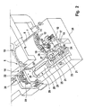
- Fig. 1 shows a compact handheld portable analyzer 1 for examining a sample, particularly a biological fluid, for a medically important ingredient such as blood, urine or saliva.
- This in Fig. 1 shown handheld analyzer 1 is used to determine the blood glucose content and has a power source 2 in the form of commercially available batteries or solar cells.
- the result of a study is displayed with a display device 3, preferably a liquid crystal display.
- the analysis handset 1 has a housing 4, which has a loading opening 5 for receiving a replaceable drum magazine 6 in a magazine compartment 7.
- the drum magazine 6 by means of an electric motor 8 is gradually rotatable about its geometric longitudinal axis, so that stored in the drum magazine 6 analytical consumable 9 can be removed through a housing opening 10 of the housing 4.
- the substantially cylindrically shaped drum magazine 6 has a plurality of annular chambers 11 arranged around its geometrical longitudinal axis, which can contain analytical consumables 9.
- the number of chambers 11 can be chosen largely arbitrary. As a rule, 10 to 100 chambers 11 are expedient, preferably 15 to 30 chambers 11 are present.
- Each of the chambers 11 has a removal opening 12 on an end face of the drum magazine 6 for removing a consumable 9 and the insertion opening 12 opposite insertion opening 13 for insertion of a plunger 14 of a removal device 29.
- the insertion openings 12 and the removal openings 13 are closed to protect the consumables 9 from harmful environmental influences with a sealing film.
- the consumables 9 are preferably designed as test strips, to which a sample can be applied.
- a reagent contained in the test strip reacts with a medically significant component of the sample, so that the result of the reaction can be evaluated with an analysis sensor 15 of the analysis handset 1.
- an analysis sensor 15 may be, for example, an optical sensor which detects a color change of a consumable 9 formed as a test strip, or be an electrical sensor which detects a change in conductivity of the sample.
- the drum magazine 6 can rotate stepwise, so that successively each of the removal openings 12 are positioned in alignment with the housing opening 10 of the housing 4 and then by means of the plunger 14 of the removal device 29 a consumable 9 can be pushed out of the chamber 11 positioned for removal ,
- a special feature of the embodiment shown is that the removal device 29 in addition to the plunger 14 a in Fig. 2 shown drivable feed roller 16 comprises.
- the conveyor roller 16 may be one of the Drum magazine 6 Grip outstanding consumables 9 and move them out of the drum magazine in whole or in part in the withdrawal direction. The conveyor roller 16 therefore makes it possible to carry out the plunger 14 substantially shorter than in devices known in the prior art, since it is sufficient if the consumable 9 can be pushed out of the chamber 11 by the plunger 14 a small distance.
- the conveyor roller 16 is preferably arranged directly adjacent to the removal opening 12 of the inserted drum magazine 6. Between the front side of the inserted drum magazine 6 and the conveyor roller 16 only a small minimum distance of about 1 mm is required so that the conveyor roller 16 and the inserted drum magazine 6 can rotate undisturbed.
- the conveying roller 16 preferably has a small diameter of about 3 to 10 mm, particularly preferably 4 to 7 mm.
- the conveyor roller 16 forms, together with a stationary relative to their conveying surface a conveying gap through which the consumable 9 is moved in the conveying direction.
- the conveyor roller 16 - as in FIGS. 3 to 7 is shown - also form a conveying gap together with a oppositely arranged counter-roller 31.
- the conveying gap preferably has a profile adapted to the consumable 9, for example in the form of a groove in the conveying surface or the counter-roller, so that a test field of the consumable 9 during removal not squeezed and thereby impaired.
- the conveying roller 16 cooperates with a stationary conveying surface, has the advantage that the removal device 29 requires less moving parts and therefore can be carried out particularly cost-effective and less susceptible to interference.
- the analysis hand-held device 1 has, in order to support a consumable 9 removed, a conveyor web 17 extending in the removal direction.
- the conveyor surface 33 forming the conveying gap 33 together with the conveying roller 16 is part of the conveyor web 17 so that it extends from the magazine compartment 7 to the housing opening 10. In this way, a removed consumable 9 is supported and guided by the conveyor web 17 on its entire conveying path.
- a further conveying roller 18, which forms a second conveying gap together with the conveying web 17, is arranged at a distance from the conveying roller 16 in the conveying direction. While the first conveyor roller 16 is arranged as close as possible to the removal opening 12 of an inserted drum magazine 6 so that a consumable 9 must protrude as little as possible from its chamber 11 in order to be gripped, the second conveyor roller 18 is as close as possible to the housing opening 10th of the housing 4, so that a consumable 9 can be pushed out as far as possible from the housing opening 10 of the housing 4.
- a consumable 9 designed as a test strip can be pushed out of the housing opening 10 of the housing 4, the easier it is to apply a sample, for example a drop of blood, to the consumable 9 without the housing 4 being contaminated by the sample ,
- the conveyor web 17 is provided with a groove 19 extending in the conveying direction, which advantageously minimizes friction occurring between the consumable 9 and the conveyor web 17.
- the conveyor web 17 is made of the smoothest possible material with a low coefficient of friction, such as polycarbonate
- the conveyor rollers 16, 18 preferably have a friction-increasing surface with the largest possible friction coefficient.
- the rollers may have a roughened surface, made of hard or soft rubber, or coated with a rubber-like plastic. If the consumables 9 have a thickness that varies over their length, the conveying roller may be spring-loaded in order to take account of thickness differences.
- the conveyor rollers 16, 18 and the plunger 14 of the removal device 29 are moved by a single drive 30.
- the tappet 14 and the conveyor rollers 16, 18 or even for each of the conveyor rollers 16, 18 to provide its own micromotor drive. But it is cheaper and therefore preferred when the removal device 29 has only one drive 30, with both the conveyor rollers 16, 18 and the plunger 14 are driven.
- the removal device 29 has a threaded rod 20 with a thread 21 which extends laterally next to the inserted drum magazine 6 and both sides protrudes beyond its front side.
- the removal device 29 has a gearbox 22, via which an electric motor belonging to the drive 30 can move the plunger 14.
- the threaded rod 20 has a gear 23 which cooperates with the gear 21, so that the threaded rod 20 via the gear 22 and the gear 23 is set in rotation.
- the gear 23 may be designed as a separate component which is attached to the threaded rod 20, or be integrated into the threaded rod 20 by, for example, a portion of the threaded rod 20 is provided with teeth. In order to make the threaded rod 20 as short as possible, the gear 23 is preferably located at or near one end of the threaded rod 20 and the thread 21 at or near the other end.
- a rotation of the threaded rod 20 can be transferred to the conveying rollers 16, 18 via the external thread 21 arranged at the other end of the threaded rod 20.
- each of the two conveyor rollers 16, 18 is provided with a shaft 24 which carries a gear 25 which engages in the thread 21 of the threaded rod 20.
- the shafts 24 and the threaded rod 20 are mounted by means of bearing rings 26 which are rotatable with low frictional resistance in matching recesses 27 of a carrier 28.
- the conveyor rollers 16, 18 can be driven about their geometric longitudinal axes both clockwise and counterclockwise in order to move a consumable 9 both in the withdrawal direction and in the opposite direction.
- This measure makes it possible to push out a consumable 9, for example a test strip, as far as possible out of the housing opening 10 of the housing 4 in order to apply a sample facilitate and then draw the consumable 9 back into the analysis handset 1.
- This makes it possible to arrange the analysis sensor 15 at a protected location in the interior of the housing 4, where disturbing environmental influences, such as scattered light, are minimized.
- the analysis sensor 15 between the two conveyor rollers 16, 18, in particular on the conveyor rollers 16, 18 opposite side of the conveyor web 17 is arranged.
- the conveyor web 17 is provided between the two conveyor rollers 16, 18 with a recess so that the analysis sensor 15 can detect a sample applied to a consumable 9.
- the extending in the conveying direction groove 19 of the conveyor web 17 is dimensioned in its width and depth so that an applied to the consumable 9 sample does not come into contact with the conveyor web 17.
- the plunger 14 is equipped with a gripping element, which can come into operative engagement with a consumable 9 and makes it possible to exercise on the plunger 14 and tensile forces on a consumable 9 can.
- the gripping element can be designed as an electromagnet which attracts an iron part of the consumable or as a mechanical hook, which, at a given tensile force, as it is exerted by the conveyor roller 16, folds over and releases the consumable 9.
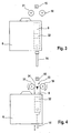
- FIGS. 3 to 7 show in a schematic representation of another embodiment of a removal device when removing a consumable 9 from a drum magazine 6.
- removal device 29 of the conveying gap 33 is not formed by the conveying roller 16 and a stationary relative to their conveying surface, but by the conveying roller 16 and a counter-roller 31 arranged opposite her.
- both the conveying roller 16 and the counter-roller 31 may each be formed drivable.
- the counter-roller 31 it is sufficient if it is rotatably mounted, so that it can be set in rotation by a passing through the conveying gap 33 consumable 9.
- the consumables 9 are designed as test strips which have a test field 32 for receiving a sample.
- the test field 32 is not affected when removing the consumable 9 from the drum magazine 6 and a sample on it can not pollute the removal device 29, in particular not the feed roller 16 and the counter-roller 31, occurs in the illustrated embodiment, the consumable 9 through the conveying gap, that the test field 32 of the consumable 9 extends transversely to the geometric axis of rotation of the conveying roller 16.
- the risk of deterioration of the test field 32 of the consumable 9 is reduced even further than that in the basis of FIG. 2 described embodiment by a conveying gap 33 with a matched to the consumable 9 profile, for example in the form of a groove 19 in which the conveying surface forming conveyor web 17 can reach.
- FIG. 3 shows the drum magazine 6 with a consumable contained therein 9 together with the removal device 29 in the starting position.
- the consumable 9 is pushed out with the plunger 14 from the drum magazine 6 and gripped by the feed roller 16 as soon as it projects into the conveying gap 33 between the feed roller 16 and the counter roller 31.
- FIG. 5 shows how the consumable 9 is pushed out of the conveyor roller 16 from the housing opening 10 of the analysis handset 1, so that a sample, such as a drop of blood, can be applied to a sample application surface 34, from which it reaches the test field 32. Subsequently, as in FIG.
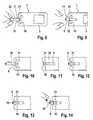
- FIGS. 8 to 14 show a further embodiment of a hand-held analyzer 1 during insertion of a consumable 9.
- This handheld analyzer 1 differs from the handheld analyzer 1 described above essentially by the fact that it has no loading port for receiving a removable drum magazine.
- analytical consumables 9 in the form of test strips are supplied to the device externally through the housing opening 10.
- a micro-switch (not shown) is actuated, by which a drive of the feed roller 16 and the counter-roller 31 is turned on.
- the consumable 9 is then gripped by the conveying roller 16 and the counter-roller 31 and drawn along the conveying path in the device interior.
- a consumable 9 is therefore from the in Fig. 10 shown input position first in the in Fig. 11 shown test position, in which it is checked if it is not spoiled. This is done by means of an optical measuring device with which a film white value of the consumable 9 is determined.
- a consumable 9 designed as a test strip has for this purpose, for example in the area of the test field 32, a section with a white plastic film, which increases in size Aging and moisture absorption discolored.
- the film white value By determining the film white value, it can be determined whether the inserted consumable 9 is spoiled. Is a consumable 9 spoiled, it is ejected by means of the feed roller 16 and the counter-roller 31 from the analysis handset 1. Is the consumable 9 still functional, it is by means of the feed roller 16 and the counter-roller 31 along the conveying path in the in Fig. 14 brought shown sample loading position. In the sample application position, the consumable 9 protrudes with one end out of the housing opening 10, so that a sample, for example a drop of blood, can be applied to the sample application surface 34.
- An important advantage of the described Anlaysehand réelles 1 is that the consumable 9 in the in Fig. 14 shown sample application position may protrude so far from the housing opening 10 that a sample can be easily applied to the sample application surface 34 without the handheld analyzer 1 soiling it.
- the test field 32 to which the sample is supplied for example by capillary forces, can be arranged so close to the sample application area 34 that the required sample volume is minimal.
Claims (17)
- Appareil d'analyse manuel pour l'analyse d'un composant médicalement pertinent dans un échantillon, en particulier d'un liquide biologique, comprenant :un capteur d'analyse (15) alimentable par un consommable analytique sur un trajet de transport,un dispositif afficheur (3),un boîtier (4) présentant une ouverture de boîtier (10) pour un consommable analytique (9),à laquelle le trajet de transport est raccordé,et un rouleau de transport (16, 18) entraînable, au moyen duquel un consommable analytique (9) pénétrant dans le trajet de transport peut être saisi et déplacé sur le trajet de transport,caractérisé en ce que le rouleau de transport (16, 18) est entraînable autour de son axe géométrique longitudinal tant dans le sens des aiguilles d'une montre que dans le sens anti-horaire, pour pouvoir déplacer un consommable analytique (9) tant dans la direction de prélèvement que dans la direction opposée.
- Appareil d'analyse manuel selon la revendication 1, caractérisé en ce que le boîtier (4) présente une ouverture de chargement (5) pour le logement d'un magasin à tambour (6) renouvelable pouvant contenir des consommables analytiques (9), en particulier des bandes de test, et présente au moins une ouverture de prélèvement (12) sur une face frontale, et
en ce que le boîtier (4) entoure un dispositif de prélèvement (29) pour le prélèvement d'un des consommables analytiques (9) hors du magasin à tambour (6),
le dispositif de prélèvement (29) comprenant le rouleau de transport (16, 18) entraînable, lequel peut saisir un consommable analytique (9) sortant du magasin à tambour (6) et pénétrant dans le trajet de transport, et déplacer celui-ci dans une direction de prélèvement en l'extrayant totalement ou partiellement du magasin à tambour (6). - Appareil d'analyse manuel selon la revendication 1 ou 2, caractérisé en ce qu'il comporte une tige de poussée (14) au moyen de laquelle un consommable (9) peut être ressorti d'un compartiment sur une longueur lui permettant d'être saisi par le rouleau de transport (16, 18) et déplacé dans la direction de déplacement.
- Appareil d'analyse manuel selon l'une des revendications précédentes, caractérisé en ce que le rouleau de transport (16, 18) forme une fente de transport (33) avec un contre-rouleau (31), au travers de laquelle le consommable (9) est déplacé.
- Appareil d'analyse manuel selon l'une des revendications 1 à 3, caractérisé en ce que le rouleau de transport (16, 18) forme une fente de transport (33) avec une surface de transport immobile par rapport à lui, par laquelle le consommable (9) est déplacé.
- Appareil d'analyse manuel selon la revendication 3 ou 4, caractérisé en ce que la fente de transport (33) présente un profil adapté au consommable (9).
- Appareil d'analyse manuel selon la revendication 6, caractérisé en ce que la surface de transport ou le contre-rouleau présentent une rainure (19) s'étendant dans la direction de transport.
- Appareil d'analyse manuel selon l'une des revendications précédentes, caractérisé en ce qu'il présente un méplat de transport (17) s'étendant le long du trajet de transport, pour le support d'un consommable (9) prélevé.
- Appareil d'analyse manuel selon la revendication 8, caractérisé en ce que la surface de transport fait partie du méplat de transport (17).
- Appareil d'analyse manuel selon l'une des revendications 2 à 9, caractérisé en ce que le rouleau de transport (16, 18) est directement contigu à la face frontale d'un magasin à tambour (6) inséré, laquelle présente l'ouverture de prélèvement (12).
- Appareil d'analyse manuel selon l'une des revendications précédentes, caractérisé en ce que le rouleau de transport (16, 18) présente une surface formée pour accroître la friction.
- Appareil d'analyse manuel selon l'une des revendications 2 à 11, caractérisé en ce que le dispositif de prélèvement (29) comporte un autre rouleau de transport (18) pour le déplacement d'un consommable (9), le premier rouleau de transport (16) et l'autre rouleau de transport (18) étant espacés entre eux le long du trajet de transport.
- Appareil d'analyse manuel selon l'une des revendications 2 à 12, caractérisé en ce que le dispositif de prélèvement (29) comporte une tige de poussée (14) insérable dans une ouverture de poussée (13) opposée à l'ouverture de prélèvement (12) pour pousser un consommable (9) hors du magasin à tambour (6).
- Appareil d'analyse manuel selon la revendication 13, caractérisé en ce que le dispositif de prélèvement (29) comporte un entraînement (30) au moyen duquel le rouleau de transport (16, 18) ainsi que la tige de poussée (14) sont entraînables ensemble.
- Appareil d'analyse manuel selon la revendication 14, caractérisé en ce que le dispositif de prélèvement (29) comporte une tige filetée (20) avec un filet (21), laquelle s'étend latéralement à côté d'un magasin à tambour (6) inséré et coopère avec un arbre (24) pour entraîner le rouleau de transport (16, 18).
- Appareil d'analyse manuel selon la revendication 15, caractérisé en ce que l'entraînement (30) comporte un engrenage (22) pour le déplacement du poussoir (14), lequel coopère avec ce dernier au moyen d'un pignon (23) disposé sur la tige filetée (20).
- Appareil d'analyse manuel selon l'une des revendications 2 à 16, caractérisé en ce que le dispositif de prélèvement (29) est réalisé de manière à permettre la réintroduction d'un consommable (9) utilisé dans un compartiment (11) du magasin à tambour (6).
Priority Applications (1)
| Application Number | Priority Date | Filing Date | Title |
|---|---|---|---|
| EP08005435A EP1936374A1 (fr) | 2004-03-04 | 2005-02-05 | Appareil manuel d'analyse doté d'une voie d'alimentation pour des produits de consommation analytiques |
Applications Claiming Priority (2)
| Application Number | Priority Date | Filing Date | Title |
|---|---|---|---|
| DE102004010529A DE102004010529B4 (de) | 2004-03-04 | 2004-03-04 | Analysehandgerät |
| PCT/EP2005/001196 WO2005085840A1 (fr) | 2004-03-04 | 2005-02-05 | Appareil d'analyse a main comportant une section de transport pour des elements d'analyse |
Related Child Applications (1)
| Application Number | Title | Priority Date | Filing Date |
|---|---|---|---|
| EP08005435A Division EP1936374A1 (fr) | 2004-03-04 | 2005-02-05 | Appareil manuel d'analyse doté d'une voie d'alimentation pour des produits de consommation analytiques |
Publications (2)
| Publication Number | Publication Date |
|---|---|
| EP1745284A1 EP1745284A1 (fr) | 2007-01-24 |
| EP1745284B1 true EP1745284B1 (fr) | 2008-05-07 |
Family
ID=34877349
Family Applications (2)
| Application Number | Title | Priority Date | Filing Date |
|---|---|---|---|
| EP08005435A Withdrawn EP1936374A1 (fr) | 2004-03-04 | 2005-02-05 | Appareil manuel d'analyse doté d'une voie d'alimentation pour des produits de consommation analytiques |
| EP05707236A Not-in-force EP1745284B1 (fr) | 2004-03-04 | 2005-02-05 | Appareil d'analyse a main comportant une section de transport pour des elements d'analyse |
Family Applications Before (1)
| Application Number | Title | Priority Date | Filing Date |
|---|---|---|---|
| EP08005435A Withdrawn EP1936374A1 (fr) | 2004-03-04 | 2005-02-05 | Appareil manuel d'analyse doté d'une voie d'alimentation pour des produits de consommation analytiques |
Country Status (8)
| Country | Link |
|---|---|
| US (1) | US7922974B2 (fr) |
| EP (2) | EP1936374A1 (fr) |
| JP (1) | JP4653801B2 (fr) |
| AT (1) | ATE394669T1 (fr) |
| CA (1) | CA2557996C (fr) |
| DE (2) | DE102004010529B4 (fr) |
| ES (1) | ES2306093T3 (fr) |
| WO (1) | WO2005085840A1 (fr) |
Families Citing this family (13)
| Publication number | Priority date | Publication date | Assignee | Title |
|---|---|---|---|---|
| US8202488B2 (en) | 2004-09-20 | 2012-06-19 | Bayer Healthcare Llc | System and method for repositioning a diagnostic test strip after inoculation |
| TW200706864A (en) * | 2005-06-03 | 2007-02-16 | Bayer Healthcare Llc | Solar-powered integrated-diagnostic instrument |
| US8562814B2 (en) * | 2006-08-03 | 2013-10-22 | Panasonic Corporation | Measurement device and sensor ejection method |
| ATE436014T1 (de) * | 2007-05-19 | 2009-07-15 | Hoffmann La Roche | Analysehandgerät zum untersuchen einer probe |
| US8394637B2 (en) | 2008-06-02 | 2013-03-12 | Roche Diagnostics Operations, Inc. | Handheld analyzer for testing a sample |
| EP2177155A1 (fr) | 2008-10-20 | 2010-04-21 | F. Hoffmann-Roche AG | Instrument de bande de test analytique avec moteur à courant continu et engrenage |
| US8147755B2 (en) | 2008-11-26 | 2012-04-03 | Roche Diagnostics Operations, Inc. | Drum type container for analytical elements |
| US8574510B2 (en) | 2009-09-30 | 2013-11-05 | Bayer Healthcare Llc | Stackable electrochemical analyte sensors, systems and methods including same |
| CN104185445B (zh) * | 2012-01-10 | 2016-08-24 | 赛诺菲-安万特德国有限公司 | 测试构件盒 |
| JP6563892B2 (ja) * | 2013-03-11 | 2019-08-21 | アセンシア・ディアベティス・ケア・ホールディングス・アーゲー | ストリップグラバー |
| US9376708B2 (en) | 2013-03-13 | 2016-06-28 | Ascensia Diabetes Care Holdings Ag | Bottled glucose sensor with no handling |
| CN105813809B (zh) * | 2013-11-27 | 2017-08-29 | 豪夫迈·罗氏有限公司 | 手柄测试带射出器 |
| US20150176053A1 (en) * | 2013-12-23 | 2015-06-25 | Cilag Gmbh International | Test strip insertion drive mechanism for analyte meter |
Family Cites Families (28)
| Publication number | Priority date | Publication date | Assignee | Title |
|---|---|---|---|---|
| US3918910A (en) | 1973-07-31 | 1975-11-11 | Olympus Optical Co | System for detecting the particular chemical constituent of a fluid |
| DE2407320A1 (de) * | 1974-02-15 | 1975-08-28 | Benzing Kontrolluhren | Geraet zur arbeits- und auftragszeiterfassung |
| US4065263A (en) | 1976-04-02 | 1977-12-27 | Woodbridge Iii Richard G | Analytical test strip apparatus |
| AU540481B2 (en) * | 1980-02-14 | 1984-11-22 | Hermann Stockburger | Authorization card |
| US4302420A (en) | 1981-01-09 | 1981-11-24 | Eastman Kodak Company | Analyzer featuring a contacting reflectometer |
| US4876204A (en) | 1984-10-11 | 1989-10-24 | Kabushiki Kaisha Kyoto Daiichi Kagaku | Method and apparatus of automatic continuous analysis using analytical implement |
| US4791461A (en) | 1984-11-27 | 1988-12-13 | Syntex (U.S.A.) Inc. | Portable analyzer |
| US4710352A (en) | 1985-09-20 | 1987-12-01 | Eastman Kodak Company | Simplified test element advancing mechanism having positive engagement with element |
| US5236078A (en) | 1986-07-30 | 1993-08-17 | Hoechst Aktiengesellschaft | Apparatus for fixing the position of the test zones of a test strip and for reversing the latter |
| US4857471A (en) | 1987-07-20 | 1989-08-15 | Eastman Kodak Company | Analyzer with wash station separate from incubator |
| US4833088A (en) | 1987-09-25 | 1989-05-23 | Miles Inc. | Reagent strip handling mechanism |
| DE3807565A1 (de) | 1988-03-08 | 1989-09-21 | Boehringer Mannheim Gmbh | Vorrichtung zur ueberfuehrung von teststreifen zu einer untersuchungseinrichtung |
| US5073342A (en) | 1989-01-05 | 1991-12-17 | Eastman Kodak Company | Reciprocating transfer mechanism |
| JP2812625B2 (ja) | 1992-10-19 | 1998-10-22 | 株式会社日立製作所 | 液体試料自動分析装置 |
| DE4328815A1 (de) | 1993-08-27 | 1995-03-02 | Boehringer Mannheim Gmbh | System zur Bevorratung von Testelementen |
| DE4425439A1 (de) | 1994-07-19 | 1996-01-25 | Boehringer Mannheim Gmbh | Teststreifenauswertegerät mit einer Transporteinheit für Teststreifen |
| US5575403A (en) | 1995-01-13 | 1996-11-19 | Bayer Corporation | Dispensing instrument for fluid monitoring sensors |
| US5510266A (en) * | 1995-05-05 | 1996-04-23 | Bayer Corporation | Method and apparatus of handling multiple sensors in a glucose monitoring instrument system |
| ATE214805T1 (de) | 1996-05-30 | 2002-04-15 | Radiometer Medical As | System zur bestimmung mindestens eines parameters mindestens einer probe einer physiologischen flüssigkeit und kassette dafür |
| DE19715031A1 (de) * | 1997-04-11 | 1998-10-15 | Boehringer Mannheim Gmbh | Magazin zur Bevorratung von Testelementen |
| SG102538A1 (en) | 1998-04-24 | 2004-03-26 | Roche Diagnostics Gmbh | Storage container for analytical devices |
| DE19819407A1 (de) * | 1998-04-30 | 1999-11-11 | Hendrik Priebs | Teststreifenbehälter für Messgeräte, die mit Einwegteststreifen arbeiten |
| DE19902601A1 (de) | 1999-01-23 | 2000-07-27 | Roche Diagnostics Gmbh | Verfahren und Vorrichtung zum Entnehmen analytischer Verbrauchsmittel aus einem Vorratsbehältnis |
| JP4216434B2 (ja) * | 2000-02-02 | 2009-01-28 | 大塚製薬株式会社 | 試験紙測定装置 |
| GB0021219D0 (en) * | 2000-08-30 | 2000-10-18 | Hypoguard Ltd | Test device |
| US6827899B2 (en) * | 2000-08-30 | 2004-12-07 | Hypoguard Limited | Test device |
| DE10156811A1 (de) * | 2001-11-20 | 2003-06-05 | Quidel Corp | Teststreifenanalysegerät |
| US20030212344A1 (en) * | 2002-05-09 | 2003-11-13 | Vadim Yuzhakov | Physiological sample collection devices and methods of using the same |
-
2004
- 2004-03-04 DE DE102004010529A patent/DE102004010529B4/de not_active Expired - Fee Related
-
2005
- 2005-02-05 WO PCT/EP2005/001196 patent/WO2005085840A1/fr active IP Right Grant
- 2005-02-05 EP EP08005435A patent/EP1936374A1/fr not_active Withdrawn
- 2005-02-05 JP JP2007501140A patent/JP4653801B2/ja not_active Expired - Fee Related
- 2005-02-05 AT AT05707236T patent/ATE394669T1/de active
- 2005-02-05 US US10/591,311 patent/US7922974B2/en not_active Expired - Fee Related
- 2005-02-05 DE DE502005004009T patent/DE502005004009D1/de active Active
- 2005-02-05 EP EP05707236A patent/EP1745284B1/fr not_active Not-in-force
- 2005-02-05 ES ES05707236T patent/ES2306093T3/es active Active
- 2005-02-05 CA CA2557996A patent/CA2557996C/fr not_active Expired - Fee Related
Also Published As
| Publication number | Publication date |
|---|---|
| DE102004010529B4 (de) | 2007-09-06 |
| ATE394669T1 (de) | 2008-05-15 |
| DE102004010529A1 (de) | 2005-09-22 |
| JP4653801B2 (ja) | 2011-03-16 |
| JP2007526464A (ja) | 2007-09-13 |
| EP1936374A1 (fr) | 2008-06-25 |
| ES2306093T3 (es) | 2008-11-01 |
| EP1745284A1 (fr) | 2007-01-24 |
| CA2557996C (fr) | 2011-04-12 |
| US20070183925A1 (en) | 2007-08-09 |
| DE502005004009D1 (de) | 2008-06-19 |
| CA2557996A1 (fr) | 2005-09-15 |
| US7922974B2 (en) | 2011-04-12 |
| WO2005085840A1 (fr) | 2005-09-15 |
Similar Documents
| Publication | Publication Date | Title |
|---|---|---|
| EP1745284B1 (fr) | Appareil d'analyse a main comportant une section de transport pour des elements d'analyse | |
| EP1574855B1 (fr) | Appareil portable d'analyse | |
| DE10361261B4 (de) | Analysehandgerät | |
| EP1022565B1 (fr) | Dispositif et méthode pour retirer des éléments d'analyse à usage unique d'un récipient de stockage | |
| EP1975610B1 (fr) | Instrument d'analyse avec magasin échangeable d'éléments de test | |
| EP1997429B1 (fr) | Lancet flexible en une systeme de lancettes | |
| EP0922959B1 (fr) | Système d'analyse des échantillons liquides | |
| DE102004057503B4 (de) | Diagnosesystem zum Ermitteln von Stoffkonzentrationen in flüssigen Proben | |
| DE60213055T2 (de) | Testvorrichtung mit Mitteln zum Aufbewahren und Dispensieren von diagnostischen Streifen | |
| EP2139396B1 (fr) | Appareil de perçage et appareil d'analyse | |
| EP1736772B1 (fr) | Dispositif de test avec un dispositif de stockage d'éléments d'analyse | |
| DE10057832C1 (de) | Blutanalysegerät | |
| DE60310160T2 (de) | Streifen zur Verpackung einer Mehrzahl von Geräten zur Flüssigkeitsentnahme und Testung sowie Verfahren zur Herstellung und Verwendung des Streifens | |
| EP2129289B1 (fr) | Système d'analyse pour la détermination d'un analyte dans un liquide corporel, et élément de prélèvement d'échantillon et d'analyse intégré jetable | |
| EP2130493A1 (fr) | Système d'analyse destiné à la détermination d'un analyte dans un liquide corporel, entrepôt pour un appareil d'analyse et procédé de production d'une plaie dans une partie du corps pour l'examen d'un liquide corporel s'écoulant | |
| WO2006108797A1 (fr) | Appareil d'analyse pour analyser un echantillon liquide au moyen d'un element de test | |
| EP1929937A1 (fr) | Dispositif et méthode pour analyser des liquides organiques | |
| EP2101646A1 (fr) | Appareil perforant | |
| WO2009030340A1 (fr) | Appaareil d'analyse pour déterminer la présence d'une substance à analyser dans un liquide organique, magasin pour un appareil d'analyse et procédé pour créer une plaie en vue d'analyser un écoulement de liquide organique | |
| EP1995594B1 (fr) | Appareil d'analyse portable pour tester des échantillons | |
| EP2135546B1 (fr) | Cassette à bande pour un appareil médical portable | |
| EP2442708B1 (fr) | Système de piquage | |
| EP1672364A1 (fr) | Système d`analyse pour analyser un échantillon de liquide avec un elément d`éssai |
Legal Events
| Date | Code | Title | Description |
|---|---|---|---|
| PUAI | Public reference made under article 153(3) epc to a published international application that has entered the european phase |
Free format text: ORIGINAL CODE: 0009012 |
|
| 17P | Request for examination filed |
Effective date: 20060715 |
|
| AK | Designated contracting states |
Kind code of ref document: A1 Designated state(s): AT BE BG CH CY CZ DE DK EE ES FI FR GB GR HU IE IS IT LI LT LU MC NL PL PT RO SE SI SK TR |
|
| 17Q | First examination report despatched |
Effective date: 20070129 |
|
| DAX | Request for extension of the european patent (deleted) | ||
| RAP1 | Party data changed (applicant data changed or rights of an application transferred) |
Owner name: ROCHE DIAGNOSTICS GMBH Owner name: F.HOFFMANN-LA ROCHE AG |
|
| GRAP | Despatch of communication of intention to grant a patent |
Free format text: ORIGINAL CODE: EPIDOSNIGR1 |
|
| GRAS | Grant fee paid |
Free format text: ORIGINAL CODE: EPIDOSNIGR3 |
|
| GRAA | (expected) grant |
Free format text: ORIGINAL CODE: 0009210 |
|
| AK | Designated contracting states |
Kind code of ref document: B1 Designated state(s): AT BE BG CH CY CZ DE DK EE ES FI FR GB GR HU IE IS IT LI LT LU MC NL PL PT RO SE SI SK TR |
|
| REG | Reference to a national code |
Ref country code: GB Ref legal event code: FG4D Free format text: NOT ENGLISH |
|
| REG | Reference to a national code |
Ref country code: CH Ref legal event code: NV Representative=s name: BOHEST AG Ref country code: CH Ref legal event code: EP |
|
| REG | Reference to a national code |
Ref country code: IE Ref legal event code: FG4D Free format text: LANGUAGE OF EP DOCUMENT: GERMAN |
|
| REF | Corresponds to: |
Ref document number: 502005004009 Country of ref document: DE Date of ref document: 20080619 Kind code of ref document: P |
|
| PG25 | Lapsed in a contracting state [announced via postgrant information from national office to epo] |
Ref country code: SI Free format text: LAPSE BECAUSE OF FAILURE TO SUBMIT A TRANSLATION OF THE DESCRIPTION OR TO PAY THE FEE WITHIN THE PRESCRIBED TIME-LIMIT Effective date: 20080507 |
|
| PG25 | Lapsed in a contracting state [announced via postgrant information from national office to epo] |
Ref country code: NL Free format text: LAPSE BECAUSE OF FAILURE TO SUBMIT A TRANSLATION OF THE DESCRIPTION OR TO PAY THE FEE WITHIN THE PRESCRIBED TIME-LIMIT Effective date: 20080507 Ref country code: FI Free format text: LAPSE BECAUSE OF FAILURE TO SUBMIT A TRANSLATION OF THE DESCRIPTION OR TO PAY THE FEE WITHIN THE PRESCRIBED TIME-LIMIT Effective date: 20080507 |
|
| REG | Reference to a national code |
Ref country code: ES Ref legal event code: FG2A Ref document number: 2306093 Country of ref document: ES Kind code of ref document: T3 |
|
| NLV1 | Nl: lapsed or annulled due to failure to fulfill the requirements of art. 29p and 29m of the patents act | ||
| PG25 | Lapsed in a contracting state [announced via postgrant information from national office to epo] |
Ref country code: PL Free format text: LAPSE BECAUSE OF FAILURE TO SUBMIT A TRANSLATION OF THE DESCRIPTION OR TO PAY THE FEE WITHIN THE PRESCRIBED TIME-LIMIT Effective date: 20080507 |
|
| REG | Reference to a national code |
Ref country code: IE Ref legal event code: FD4D |
|
| PG25 | Lapsed in a contracting state [announced via postgrant information from national office to epo] |
Ref country code: IS Free format text: LAPSE BECAUSE OF FAILURE TO SUBMIT A TRANSLATION OF THE DESCRIPTION OR TO PAY THE FEE WITHIN THE PRESCRIBED TIME-LIMIT Effective date: 20080907 |
|
| PG25 | Lapsed in a contracting state [announced via postgrant information from national office to epo] |
Ref country code: SE Free format text: LAPSE BECAUSE OF FAILURE TO SUBMIT A TRANSLATION OF THE DESCRIPTION OR TO PAY THE FEE WITHIN THE PRESCRIBED TIME-LIMIT Effective date: 20080807 Ref country code: IE Free format text: LAPSE BECAUSE OF FAILURE TO SUBMIT A TRANSLATION OF THE DESCRIPTION OR TO PAY THE FEE WITHIN THE PRESCRIBED TIME-LIMIT Effective date: 20080507 Ref country code: LT Free format text: LAPSE BECAUSE OF FAILURE TO SUBMIT A TRANSLATION OF THE DESCRIPTION OR TO PAY THE FEE WITHIN THE PRESCRIBED TIME-LIMIT Effective date: 20080507 Ref country code: CZ Free format text: LAPSE BECAUSE OF FAILURE TO SUBMIT A TRANSLATION OF THE DESCRIPTION OR TO PAY THE FEE WITHIN THE PRESCRIBED TIME-LIMIT Effective date: 20080507 Ref country code: DK Free format text: LAPSE BECAUSE OF FAILURE TO SUBMIT A TRANSLATION OF THE DESCRIPTION OR TO PAY THE FEE WITHIN THE PRESCRIBED TIME-LIMIT Effective date: 20080507 |
|
| PG25 | Lapsed in a contracting state [announced via postgrant information from national office to epo] |
Ref country code: PT Free format text: LAPSE BECAUSE OF FAILURE TO SUBMIT A TRANSLATION OF THE DESCRIPTION OR TO PAY THE FEE WITHIN THE PRESCRIBED TIME-LIMIT Effective date: 20081007 Ref country code: RO Free format text: LAPSE BECAUSE OF FAILURE TO SUBMIT A TRANSLATION OF THE DESCRIPTION OR TO PAY THE FEE WITHIN THE PRESCRIBED TIME-LIMIT Effective date: 20080507 Ref country code: SK Free format text: LAPSE BECAUSE OF FAILURE TO SUBMIT A TRANSLATION OF THE DESCRIPTION OR TO PAY THE FEE WITHIN THE PRESCRIBED TIME-LIMIT Effective date: 20080507 |
|
| PLBE | No opposition filed within time limit |
Free format text: ORIGINAL CODE: 0009261 |
|
| STAA | Information on the status of an ep patent application or granted ep patent |
Free format text: STATUS: NO OPPOSITION FILED WITHIN TIME LIMIT |
|
| 26N | No opposition filed |
Effective date: 20090210 |
|
| PG25 | Lapsed in a contracting state [announced via postgrant information from national office to epo] |
Ref country code: EE Free format text: LAPSE BECAUSE OF FAILURE TO SUBMIT A TRANSLATION OF THE DESCRIPTION OR TO PAY THE FEE WITHIN THE PRESCRIBED TIME-LIMIT Effective date: 20080507 Ref country code: BG Free format text: LAPSE BECAUSE OF FAILURE TO SUBMIT A TRANSLATION OF THE DESCRIPTION OR TO PAY THE FEE WITHIN THE PRESCRIBED TIME-LIMIT Effective date: 20080807 |
|
| BERE | Be: lapsed |
Owner name: F.HOFFMANN-LA ROCHE A.G. Effective date: 20090228 Owner name: ROCHE DIAGNOSTICS G.M.B.H. Effective date: 20090228 |
|
| PG25 | Lapsed in a contracting state [announced via postgrant information from national office to epo] |
Ref country code: MC Free format text: LAPSE BECAUSE OF NON-PAYMENT OF DUE FEES Effective date: 20090228 |
|
| PG25 | Lapsed in a contracting state [announced via postgrant information from national office to epo] |
Ref country code: BE Free format text: LAPSE BECAUSE OF NON-PAYMENT OF DUE FEES Effective date: 20090228 |
|
| PG25 | Lapsed in a contracting state [announced via postgrant information from national office to epo] |
Ref country code: GR Free format text: LAPSE BECAUSE OF FAILURE TO SUBMIT A TRANSLATION OF THE DESCRIPTION OR TO PAY THE FEE WITHIN THE PRESCRIBED TIME-LIMIT Effective date: 20080808 |
|
| PG25 | Lapsed in a contracting state [announced via postgrant information from national office to epo] |
Ref country code: LU Free format text: LAPSE BECAUSE OF NON-PAYMENT OF DUE FEES Effective date: 20090205 |
|
| PGFP | Annual fee paid to national office [announced via postgrant information from national office to epo] |
Ref country code: CH Payment date: 20110103 Year of fee payment: 7 Ref country code: AT Payment date: 20110124 Year of fee payment: 7 Ref country code: FR Payment date: 20110201 Year of fee payment: 7 Ref country code: IT Payment date: 20110219 Year of fee payment: 7 |
|
| PG25 | Lapsed in a contracting state [announced via postgrant information from national office to epo] |
Ref country code: HU Free format text: LAPSE BECAUSE OF FAILURE TO SUBMIT A TRANSLATION OF THE DESCRIPTION OR TO PAY THE FEE WITHIN THE PRESCRIBED TIME-LIMIT Effective date: 20081108 |
|
| PGFP | Annual fee paid to national office [announced via postgrant information from national office to epo] |
Ref country code: ES Payment date: 20110222 Year of fee payment: 7 Ref country code: GB Payment date: 20110124 Year of fee payment: 7 |
|
| PG25 | Lapsed in a contracting state [announced via postgrant information from national office to epo] |
Ref country code: TR Free format text: LAPSE BECAUSE OF FAILURE TO SUBMIT A TRANSLATION OF THE DESCRIPTION OR TO PAY THE FEE WITHIN THE PRESCRIBED TIME-LIMIT Effective date: 20080507 |
|
| PG25 | Lapsed in a contracting state [announced via postgrant information from national office to epo] |
Ref country code: CY Free format text: LAPSE BECAUSE OF FAILURE TO SUBMIT A TRANSLATION OF THE DESCRIPTION OR TO PAY THE FEE WITHIN THE PRESCRIBED TIME-LIMIT Effective date: 20080507 |
|
| REG | Reference to a national code |
Ref country code: CH Ref legal event code: PL |
|
| GBPC | Gb: european patent ceased through non-payment of renewal fee |
Effective date: 20120205 |
|
| PG25 | Lapsed in a contracting state [announced via postgrant information from national office to epo] |
Ref country code: LI Free format text: LAPSE BECAUSE OF NON-PAYMENT OF DUE FEES Effective date: 20120229 Ref country code: CH Free format text: LAPSE BECAUSE OF NON-PAYMENT OF DUE FEES Effective date: 20120229 |
|
| REG | Reference to a national code |
Ref country code: FR Ref legal event code: ST Effective date: 20121031 |
|
| PG25 | Lapsed in a contracting state [announced via postgrant information from national office to epo] |
Ref country code: IT Free format text: LAPSE BECAUSE OF NON-PAYMENT OF DUE FEES Effective date: 20120205 |
|
| REG | Reference to a national code |
Ref country code: AT Ref legal event code: MM01 Ref document number: 394669 Country of ref document: AT Kind code of ref document: T Effective date: 20120205 |
|
| PG25 | Lapsed in a contracting state [announced via postgrant information from national office to epo] |
Ref country code: GB Free format text: LAPSE BECAUSE OF NON-PAYMENT OF DUE FEES Effective date: 20120205 Ref country code: FR Free format text: LAPSE BECAUSE OF NON-PAYMENT OF DUE FEES Effective date: 20120229 Ref country code: AT Free format text: LAPSE BECAUSE OF NON-PAYMENT OF DUE FEES Effective date: 20120205 |
|
| REG | Reference to a national code |
Ref country code: ES Ref legal event code: FD2A Effective date: 20130709 |
|
| PG25 | Lapsed in a contracting state [announced via postgrant information from national office to epo] |
Ref country code: ES Free format text: LAPSE BECAUSE OF NON-PAYMENT OF DUE FEES Effective date: 20120206 |
|
| REG | Reference to a national code |
Ref country code: DE Ref legal event code: R081 Ref document number: 502005004009 Country of ref document: DE Owner name: ROCHE DIABETES CARE GMBH, DE Free format text: FORMER OWNER: ROCHE DIAGNOSTICS GMBH, 68305 MANNHEIM, DE |
|
| PGFP | Annual fee paid to national office [announced via postgrant information from national office to epo] |
Ref country code: DE Payment date: 20210113 Year of fee payment: 17 |
|
| REG | Reference to a national code |
Ref country code: DE Ref legal event code: R119 Ref document number: 502005004009 Country of ref document: DE |
|
| PG25 | Lapsed in a contracting state [announced via postgrant information from national office to epo] |
Ref country code: DE Free format text: LAPSE BECAUSE OF NON-PAYMENT OF DUE FEES Effective date: 20220901 |