EP1744834B1 - Pompe, appareil de distribution et procede correspondant pour extraire du liquide ou une masse pateuse - Google Patents
Pompe, appareil de distribution et procede correspondant pour extraire du liquide ou une masse pateuse Download PDFInfo
- Publication number
- EP1744834B1 EP1744834B1 EP05739530A EP05739530A EP1744834B1 EP 1744834 B1 EP1744834 B1 EP 1744834B1 EP 05739530 A EP05739530 A EP 05739530A EP 05739530 A EP05739530 A EP 05739530A EP 1744834 B1 EP1744834 B1 EP 1744834B1
- Authority
- EP
- European Patent Office
- Prior art keywords
- pipe
- cylinder
- hollow plunger
- pump
- external accessory
- Prior art date
- Legal status (The legal status is an assumption and is not a legal conclusion. Google has not performed a legal analysis and makes no representation as to the accuracy of the status listed.)
- Not-in-force
Links
Images

Classifications
-
- A—HUMAN NECESSITIES
- A47—FURNITURE; DOMESTIC ARTICLES OR APPLIANCES; COFFEE MILLS; SPICE MILLS; SUCTION CLEANERS IN GENERAL
- A47K—SANITARY EQUIPMENT NOT OTHERWISE PROVIDED FOR; TOILET ACCESSORIES
- A47K5/00—Holders or dispensers for soap, toothpaste, or the like
- A47K5/06—Dispensers for soap
- A47K5/12—Dispensers for soap for liquid or pasty soap
- A47K5/1202—Dispensers for soap for liquid or pasty soap dispensing dosed volume
- A47K5/1204—Dispensers for soap for liquid or pasty soap dispensing dosed volume by means of a rigid dispensing chamber and pistons
- A47K5/1207—Dispensing from the bottom of the dispenser with a vertical piston
-
- B—PERFORMING OPERATIONS; TRANSPORTING
- B05—SPRAYING OR ATOMISING IN GENERAL; APPLYING FLUENT MATERIALS TO SURFACES, IN GENERAL
- B05B—SPRAYING APPARATUS; ATOMISING APPARATUS; NOZZLES
- B05B11/00—Single-unit hand-held apparatus in which flow of contents is produced by the muscular force of the operator at the moment of use
- B05B11/01—Single-unit hand-held apparatus in which flow of contents is produced by the muscular force of the operator at the moment of use characterised by the means producing the flow
- B05B11/10—Pump arrangements for transferring the contents from the container to a pump chamber by a sucking effect and forcing the contents out through the dispensing nozzle
- B05B11/1042—Components or details
- B05B11/1073—Springs
- B05B11/1074—Springs located outside pump chambers
-
- B—PERFORMING OPERATIONS; TRANSPORTING
- B05—SPRAYING OR ATOMISING IN GENERAL; APPLYING FLUENT MATERIALS TO SURFACES, IN GENERAL
- B05B—SPRAYING APPARATUS; ATOMISING APPARATUS; NOZZLES
- B05B11/00—Single-unit hand-held apparatus in which flow of contents is produced by the muscular force of the operator at the moment of use
- B05B11/0005—Components or details
- B05B11/0059—Components or details allowing operation in any orientation, e.g. for discharge in inverted position
-
- B—PERFORMING OPERATIONS; TRANSPORTING
- B05—SPRAYING OR ATOMISING IN GENERAL; APPLYING FLUENT MATERIALS TO SURFACES, IN GENERAL
- B05B—SPRAYING APPARATUS; ATOMISING APPARATUS; NOZZLES
- B05B11/00—Single-unit hand-held apparatus in which flow of contents is produced by the muscular force of the operator at the moment of use
- B05B11/01—Single-unit hand-held apparatus in which flow of contents is produced by the muscular force of the operator at the moment of use characterised by the means producing the flow
- B05B11/10—Pump arrangements for transferring the contents from the container to a pump chamber by a sucking effect and forcing the contents out through the dispensing nozzle
- B05B11/1001—Piston pumps
- B05B11/1023—Piston pumps having an outlet valve opened by deformation or displacement of the piston relative to its actuating stem
-
- B—PERFORMING OPERATIONS; TRANSPORTING
- B05—SPRAYING OR ATOMISING IN GENERAL; APPLYING FLUENT MATERIALS TO SURFACES, IN GENERAL
- B05B—SPRAYING APPARATUS; ATOMISING APPARATUS; NOZZLES
- B05B11/00—Single-unit hand-held apparatus in which flow of contents is produced by the muscular force of the operator at the moment of use
- B05B11/01—Single-unit hand-held apparatus in which flow of contents is produced by the muscular force of the operator at the moment of use characterised by the means producing the flow
- B05B11/10—Pump arrangements for transferring the contents from the container to a pump chamber by a sucking effect and forcing the contents out through the dispensing nozzle
- B05B11/1001—Piston pumps
Definitions
- the present invention relates to a pump for removing liquid or pasty mass, in particular liquid soap, creams, disinfectants, foods, or other flowable substances from a reservoir, in particular a contractible storage container, and a corresponding dispensing apparatus and a corresponding method for removing liquid or pasty mass.
- pumps or dispensing apparatus are known in a variety of configurations such as, for example US 4842495 .
- pumps for the removal of liquid soap are known, having a chamber-forming body, hereinafter referred to as a cylinder, two-way valves, also called check valves, and having a piston guided in the cylinder.
- These pumps usually contain at least some metal parts, such as metal balls for one-way valves and metal springs for preloading the one-way valves in the closed position.
- metal parts has the disadvantage that the pumps can not easily be ground in plastic mills for recycling because most plastic grinders can not tolerate metal parts. A prior separation of the plastic parts from the metal parts would mean a considerable effort.
- a pump for the removal of liquid soap which has a cylinder which is connected via a plastic flap valve in such a way with the reservoir that the liquid can indeed get out of the reservoir into the cylinder, but prevents backflow as possible shall be.
- a longitudinally movable back and forth piston is arranged, which consists of an upwardly, ie in the direction of the check valve, closed application tube which spaced from each other at its upper end has two sealing elements whose respective diameter corresponds to the inner diameter of the cylinder. Between the two sealing elements openings are provided transversely to the longitudinal direction in the application tube, which are connected to the central application channel of the application tube.
- the above the openings arranged sealing element is an elastic sealing lip, whereas the lower sealing element is a rigid plastic ring.
- the soap in the upper cylinder area can not pass back into the reservoir through the valve, if the pressure builds up sufficiently, the soap pushes past the elastic sealing lip into the intermediate space between the two sealing elements and from there through the openings in the application tube, which finally releases the soap to the environment.
- the known pump has the disadvantage that the non-return valve loses its sealing effect over time, for example due to dried soap residue in the region of the valve flap.
- it is a non-return valve made entirely of plastic to a relatively elastic component, which also adversely affects the sealing effect.
- ambient air flows into the reservoir.
- the result is that in the reservoir, it is usually a contraction-capable reservoir, no sufficient vacuum can be built.
- the vacuum is mandatory for optimal functioning of the check valves required.
- the container can not be optimally compressed, so that consequently the liquid soap can not be completely sucked out. Because the reservoir can not be optimally compressed with the known pump, a non-usable residual amount of 5 to 20% of the original content in the reservoir regularly remains.
- the present invention seeks to provide a pump for removing liquid or pasty mass, in particular liquid soap, and a corresponding dispensing apparatus and a corresponding method, whereby an improved sealing effect can be achieved and what the remaining Residual amount in the reservoir is reducible.
- a pump for removing liquid or pasty mass, in particular liquid soap, from a reservoir, in particular a contractible supply container comprising a cylinder, a hollow piston arranged inside the cylinder, at least partially within the hollow piston disposed outer auxiliary tube and disposed at least partially within the outer auxiliary tube inner application tube, wherein the inner application tube is movable relative to the outer auxiliary tube and cooperates with the outer auxiliary tube such that movement of the inner application tube causes movement of the outer auxiliary tube, wherein the outer auxiliary tube is movable relative to the hollow piston and cooperates with the hollow piston such that a movement of the outer auxiliary tube causes a movement of the hollow piston, wherein the hollow piston is movable relative to the cylinder, wherein at least one opening is provided in the cylinder, which can connect the space within the reservoir with the space inside the cylinder and which can be opened and closed by the hollow piston, wherein in the hollow piston an opening is provided which can be opened and closed by the inner application tube
- the pump according to the invention is completely without a check valve and elastic sealing lips, and thus dispenses with the parts which, in the prior art, adversely affect the sealing effect and thus the build-up of the vacuum in the reservoir.
- this pump differs from the prior art in that simultaneously with the discharge of the liquid from the cylinder to the environment new liquid from the reservoir is sucked into the cylinder, so according to the invention a self-suction is realized.
- the present invention enables optimal evacuation of the Reservoirs and a reduction of the remaining remaining amount of liquid.
- the one cylinder is provided with a circumferential side wall, an upper end wall and a bottom.
- the hollow piston which is arranged within the cylinder, provided with a circumferential side wall, an upper end wall and a bottom.
- the outer auxiliary tube which is at least partially disposed within the hollow piston, provided with a circumferential tube wall, an upper, open end and a lower, open end.
- the inner application tube which is at least partially disposed within the outer auxiliary tube, provided with a circumferential tube wall, an upper, closed end and a lower, open end, wherein at least one opening is arranged transversely to the longitudinal direction in the upper part of the tube wall.
- the cylinder is divided into an upper and a lower chamber, wherein the upper chamber as the space between the upper end wall of the cylinder and the upper end wall of the hollow piston and the lower chamber as the space between the upper end wall of the hollow piston and the Bottom of the cylinder is defined, wherein the cylinder has an opening in the bottom, through which the outer auxiliary tube from the environment into the interior of the cylinder, and one or more Having openings in a region which is covered on the inside of the hollow piston.
- the hollow piston is movably mounted in the cylinder and the side wall of the hollow piston in sealing, sliding connection with the side wall of the cylinder, wherein the hollow piston is movable between a lower end position in which the openings in the cylinder in the inside of the hollow piston coverable area are sealingly covered, and an upper end position in which the openings in the cylinder in the inside of the hollow piston can be covered over area, wherein the hollow piston has at least one opening in the bottom and an opening in the upper end wall.
- the outer auxiliary tube is movably supported in the opening in the bottom of the cylinder and the tube wall of the outer auxiliary tube in sealing, sliding connection with the opening in the bottom of the cylinder, wherein the outer auxiliary tube is movable between a lower end position, in the the upper end of the outer auxiliary tube being spaced from the upper end wall of the hollow piston, and an upper end position sealingly closing the upper end of the outer auxiliary tube with the upper end wall of the hollow piston defining an intermediate position between the lower end position and the upper end position; in which the upper end of the outer auxiliary tube sealingly closes with the upper end wall of the hollow piston when the hollow piston is in the lower end position, and spaced from the upper end wall of the hollow piston, when the hollow piston is in the upper end position, wherein a protruding element on the outer H ilfsrohr is provided, which cooperates with a part of the hollow piston.
- the inner application tube is movably mounted in the outer auxiliary tube and the tube wall of the inner application tube in sealing, sliding connection with the tube wall of the outer auxiliary tube, wherein the inner application tube is movable relative to the outer auxiliary tube between a closed position in which Opening in the tube wall of the inner application tube is sealingly covered by the upper end of the tube wall of the outer auxiliary tube, and an open position in which the opening in the tube wall of the inner application tube is free, wherein the diameter of the upper end of the inner application tube is smaller than that Diameter of the opening in the upper end wall of the hollow piston and wherein a projecting element is provided on the inner application tube, which cooperates with a part of the outer auxiliary tube.
- a receiving disc for connection to the movable part of a dispensing apparatus is provided, which is connected to the inner application tube and is disposed so far below the lower end of the outer auxiliary tube that between the upper end of the receiving disc and the lower end of the outer auxiliary tube, a distance is provided when the inner application tube is in the closed position, and the upper end of the receiving disc and the lower end of the outer auxiliary tube touch each other when the inner application tube is in the open position.
- the bottom of the cylinder is part of an insert, which can seal the reservoir against the environment sealing.
- the openings in the cylinder in the region which can be covered on the inside by the hollow piston are arranged in the side wall of the cylinder. Preferably, these openings are near the floor.
- the hollow piston touches the bottom of the cylinder in its lower end position.
- the protruding element on the outer auxiliary tube which cooperates with a part of the hollow piston, defines the lower end position of the outer auxiliary tube, since the hollow piston undergoes a stop on the cylinder bottom.
- the diameter of the opening in the bottom of the hollow piston is equal to the inner diameter of the hollow piston. In this way, the bottom is formed solely by the lower edge of the side wall of the hollow piston, which brings a saving of material with it.
- the projecting element on the outer auxiliary tube may be an at least partially circumferential fold or a projection.
- a circumferential fold or a projection may be provided as a projecting element.
- the cooperating with the projecting element part of the hollow piston may be a stop means, in particular connected to the side wall of the hollow piston is.
- the cooperating with the projecting element part of the hollow piston may also be the upper end wall or the bottom of the hollow piston.
- the stop means which represents the cooperating with the protruding element on the outer auxiliary tube part of the hollow piston, one or more webs or a ring with passages, wherein the passages connect the area above the stop means with the area below the stop means.
- the receiving disc has a device with which the distance between the upper end of the receiving disc and the lower end of the outer auxiliary tube is changeable when the inner application tube is in the closed position, ie in the case where the distance between the pickup disk and the auxiliary pipe is maximum.
- the spacing adjusting means may form an upper part of the receiving disk and be movably connected to a lower part of the receiving disk or to the inner application pipe such that the distance between the lower part of the receiving disk and the upper part of the receiving disk is changeable.
- a particularly simple operation of this adjusting device can be achieved in that the upper part of the receiving disk is connected to the lower part of the receiving disk or with the inner application pipe by a thread, such that a rotation of the upper part relative to the lower part of the receiving disk or a rotation of the upper part of the receiving disc relative to the inner application tube leads to a change in the distance between the lower part and the upper part of the receiving disc.
- At least one return spring is provided, which acts directly or indirectly on the inner application tube. It is also conceivable that several return springs act directly and / or indirectly on the inner application tube. According to the prior art, in order to complete a pumping operation and to return the pump to its rest position, a dispensing apparatus with its own return spring was previously required.
- Such a structural unit is particularly suitable as a closure of a reservoir for liquid or pasty mass. If a pump provided with a return spring is placed in or onto the opening of a reservoir, for example screwed or welded to the reservoir, the reservoir can also be used or stored independently of a dispensing apparatus.
- the pump and / or the reservoir is provided with a simple fastening device such as a retaining groove, instead of a complexly constructed dispensing apparatus, it is relatively easy to construct and correspondingly inexpensive wall brackets or the like can be used to store the reservoir.
- a unit of pump and reservoir is particularly suitable as food packaging, for example for mayonnaise, ketchup, mustard or the like.
- the object is also achieved by a dispensing apparatus for removing liquid, in particular liquid soap, with a pump, as described above.
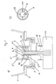
- the dispensing apparatus shown in Fig. 1a) is equipped with a reservoir 1 in the form of a contractible storage bottle, which is mounted on a fixed receptacle 2 of the dispensing apparatus.
- a union nut 3 is screwed, which clamps an insert 4 in the opening of the reservoir 1 sealingly.
- the middle part of the insert 4 forms the bottom of a cylinder 5, which is arranged in the interior of the reservoir 1.
- a hollow piston 6 is arranged with a circumferential side wall, an upper end wall and a bottom.
- the cylinder 5 is subdivided into an upper chamber 5 'and a lower chamber 5 ".
- a central opening 6a is located in the upper end wall of the hollow piston 6.
- the upper part of an outer auxiliary pipe 7 is arranged The upper end of the outer auxiliary tube 7 has an opening 7a
- the upper part of an inner application tube 8 is arranged, which has a circumferential tube wall, an upper, closed end and a lower, open end, wherein in the upper part of the tube wall of the inner application tube 8, a plurality of openings 8a are provided transversely to the longitudinal direction, which are covered in the illustrated case by the outer auxiliary tube 7.
- the cylinder has openings 5a in its side wall, which are arranged near the ground and are covered by the side wall of the hollow piston 6 in the illustrated case.
- the lower part of the application tube 8, which protrudes from the outer auxiliary tube 7, is connected to a receiving disc 9, which in turn is connected via retaining clips 10 with a movable part 11 of the dispensing apparatus.
- the receiving disc 9 is formed such that between its upper end and the lower end of the outer auxiliary tube 7, a distance 12 remains, which defines an inner stroke.
- the lower end of the inner application tube 8 is freely connected to the environment.
- the outer auxiliary tube 7 supports a projection 13 at its upper end, which is an integral part of the hollow piston 6.
- This arrangement is shown schematically in Fig. 1b) from above.
- the stop means 13 has four webs 14 on which the projection of the outer auxiliary tube 7 rests, on which in turn a protruding element, likewise in the form of a projection at the upper end, of the inner application tube 8 is supported.
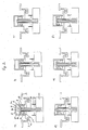
- Fig. 2a shows the rest state, in which the openings 5a are sealingly covered by the hollow piston 6, so that between the reservoir 1, which is not shown here, and the interior of the cylinder 5 no Fluid exchange is possible.
- the inner application tube 8 is in its closed position, so that the openings 8a, which represent the passage from the cylinder 5 to the application tube 8, are closed. So it is also no liquid discharge into the environment possible.
- Fig. 2b shows the state in which now the user operates the movable part 11 of the dispensing apparatus.
- the receiving disc 9 and consequently the associated application tube 8 moves upward until the upper end of the receiving disc 9 abuts against the lower end of the outer auxiliary tube 7.
- the inner application tube 8 has moved to its open position in which the openings 8a are free and a passage between the cylinder 5 and the environment is formed.
- the movable part 11 of the dispensing apparatus was further moved upward, so that the outer auxiliary tube 7 was moved from its lower end position upwards, since the receiving disk 9, the movement of the movable part 11 of the dispensing apparatus on the outer auxiliary tube transfers.
- the outer auxiliary tube 7 is located in the illustrated case in an intermediate position between the lower end position and the upper end position in which its upper end sealingly seals with the upper end wall of the hollow piston 6. At this time, therefore, the upper cylinder chamber 5 'is separated from the lower cylinder chamber 5 "such that no liquid can pass from the upper to the lower chamber.
- the openings 5a are no longer covered by the hollow piston 6, so that liquid is sucked from the reservoir 1 into the enlarged volume of the lower cylinder chamber 5 "by the negative pressure formed there, so that liquid is simultaneously sucked into the cylinder 5 and out of the cylinder 5 delivered to the environment.
- FIGS. 2e), f) and a) now show the sequence as soon as the user releases the dispensing apparatus.
- the movable part 11 of the dispensing apparatus moves down, which is achieved for example by a return spring, not shown, which acts directly or indirectly on the movable part 11 of the dispensing apparatus.
- the inner application tube 8 since it is connected via the receiving disk 9 and the brackets 10 with the movable part 11, moved downward.
- the upper chamber 5 'and the lower chamber 5 "of the cylinder 5 are still separated from each other.
- Fig. 2f shows that further down moving the movable part 11 of the dispensing apparatus and thus the inner application tube 8 and the outer auxiliary tube 7 is caused to move from its upper end position to its lower end position, wherein in Fig. 2f) the intermediate position and in Fig. 2a), the lower end position is shown.
- This is effected by providing a projection at the upper end of the application tube 8, which cooperates with a stop means, a chamfered phase, at the upper end of the outer auxiliary tube.
- the hollow piston 6 in that the hollow piston 6 is returned to its lower end position.
- the hollow piston 6 comprises a stop means 13 which cooperates with the projecting element of the outer auxiliary tube 7 and transmits the movement of the outer auxiliary tube to the remaining hollow body 6. Since the opening 6a in the upper end wall of the hollow piston 6 is opened by the return of the outer auxiliary tube 7 and the hollow piston 6, once it is in its lower position, the openings 5a in the cylinder 5 to the reservoir 1 closes again, the in the lower cylinder chamber 5 "distributed liquid evenly throughout the cylinder 5. A backflow into the reservoir 1 is not possible.
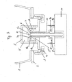
- FIG. 3 shows a dispensing apparatus and a pump according to the principle as described above, with the difference that the receiving disk 9 is divided into an upper part 9a and a lower part 9b.
- the upper part 9a forms a device with which the distance 12 between the upper end of the Receptacle 9 and the lower end of the outer auxiliary tube 7 is changeable when the inner application tube 8 is in the closed position, ie in the case in which the distance 12 between the receiving plate 9 and auxiliary tube 7 is maximum.
- the upper part 9a is threadedly connected to the lower part 9b, so that the upper part 9a can be turned relative to the lower part 9b. If the part 9a is turned upwards relative to the part 9b, the distance 12 is reduced. This has the advantage that the inner stroke and thus the delivery quantity of liquid soap can be adjusted.
- FIG. 4 shows two further exemplary embodiments of a pump according to the invention, which comprise as a special feature a return spring 15 or 16 integrated into the pump.
- a return spring 15 is provided, which is arranged around the outer auxiliary tube 7 and is supported on one side on the outside of the insert 4 and on the other side on the receiving plate 9. Since the receiving disk 9, which is firmly connected to the inner application tube 8 is, relative to the insert 4 is movable, which is fixedly connected to the cylinder 5, the return spring 15 acts in this case indirectly on the inner application tube 8 a.
- the return spring 15 allows the movement to take place automatically starting from the state shown in FIG. 2d) up to the state shown in FIG. 2a).
- the openings 5a are closed in the side wall of the cylinder 5 after a pumping operation by the pump's own return spring 15 acts indirectly on the inner application tube 8 and an overlap of the openings 5a through the side wall of the hollow piston 6, with the inner application tube 8 via the outer auxiliary tube 7 is in operative connection, forced.
- FIG. 4b The principle described above is also the basis of the embodiment of FIG. 4b), in which a return spring 16 is provided, which is arranged in the interior of the cylinder 5 and to one side on the inside of the cylinder 5 and the other side at the inner Application tube 8 is supported.
- the return spring 16 acts directly on the inner application tube 8 and also allows the movement to take place automatically, starting from the state shown in FIG. 2d) up to the state shown in FIG. 2a).
Landscapes
- Health & Medical Sciences (AREA)
- Public Health (AREA)
- Reciprocating Pumps (AREA)
- Containers And Packaging Bodies Having A Special Means To Remove Contents (AREA)
- Feeding, Discharge, Calcimining, Fusing, And Gas-Generation Devices (AREA)
- Electrical Discharge Machining, Electrochemical Machining, And Combined Machining (AREA)
Claims (24)
- Pompe destinée à prélever un liquide ou une masse pâteuse, en particulier un savon liquide, à partir d'un réservoir (1), en particulier un réservoir de stockage capable de se contracter, comprenant un cylindre (5), un piston creux (6) disposé à l'intérieur du cylindre (5), un tube auxiliaire extérieur (7) disposé au moins en partie à l'intérieur du piston creux (6) et un tube d'application interne (8) disposé au moins en partie à l'intérieur du tube auxiliaire extérieur (7), dans laquelle le tube d'application interne (8) est mobile par rapport au tube auxiliaire extérieur (7) et coopère avec le tube auxiliaire extérieur (7) de telle façon qu'un déplacement du tube d'application interne (8) provoque un déplacement du tube auxiliaire extérieur (7), le tube auxiliaire extérieur (7) est mobile par rapport au piston creux (6) et coopère avec le piston creux (6) de telle façon qu'un déplacement du tube auxiliaire extérieur (7) provoque un déplacement du piston creux (6), le piston creux (6) est mobile par rapport au cylindre (5), au moins une ouverture (5a) qui permet de relier l'espace à l'intérieur du réservoir (1) à l'espace à l'intérieur du cylindre (5) et qui peut être ouverte et fermée par le piston creux (6) est prévue dans le cylindre (5), une ouverture (6a) qui peut être ouverte et fermée par le tube d'application interne (8) ensemble avec le tube auxiliaire extérieur (7) est prévue dans le piston creux (6), une ouverture (7a) qui peut être ouverte et fermée par le tube d'application interne (8) est prévue dans le tube auxiliaire extérieur (7), au moins une ouverture (8a) qui peut être ouverte et fermée par le tube auxiliaire extérieur (7) de façon à pouvoir en même temps délivrer du liquide ou de la masse pâteuse à l'environnement par le biais du cylindre (5) à travers le tube d'application interne (8) et en aspirer à partir du réservoir (1) dans le cylindre (5) est prévue dans le tube d'application interne (8).
- Pompe selon la revendication 1, caractérisée en ce que le cylindre (5) comporte une paroi latérale enveloppante, une paroi frontale supérieure et un fond.
- Pompe selon la revendication 1 ou la revendication 2, caractérisée en ce que le piston creux (6) qui est disposé à l'intérieur du cylindre (5) comporte une paroi latérale enveloppante, une paroi frontale supérieure et un fond.
- Pompe selon l'une des revendications 1 à 3, caractérisée en ce que le tube auxiliaire extérieur (7) qui est disposé au moins en partie à l'intérieur du piston creux (6) comporte une paroi tubulaire enveloppante, une extrémité supérieure ouverte et une extrémité inférieure ouverte.
- Pompe selon l'une des revendications 1 à 4, caractérisée en ce que le tube d'application interne (8) qui est disposé au moins en partie à l'intérieur du tube auxiliaire extérieur (7) comporte une paroi tubulaire enveloppante, une extrémité supérieure fermée et une extrémité inférieure ouverte, l'ouverture (8a) étant disposée dans la partie supérieure de la paroi du tube perpendiculairement au sens longitudinal.
- Pompe selon l'une des revendications 1 à 5, caractérisée en ce que le cylindre (5) est divisé en une chambre supérieure (5') et une chambre inférieure (5 "), la chambre supérieure (5') étant définie comme l'espace entre la paroi frontale supérieure du cylindre (5) et la paroi frontale supérieure du piston creux (6) et la chambre inférieure (5") comme l'espace entre la paroi frontale supérieure du piston creux (6) et le fond du cylindre (5), le cylindre (5) présentant une ouverture dans le fond, à travers laquelle le tube auxiliaire extérieur (7) s'étend depuis l'environnement dans l'intérieur du cylindre (5), et une ou plusieurs ouvertures (5a) dans une zone qui peut être recouverte de l'intérieur par le piston creux (6).
- Pompe selon l'une des revendications 1 à 6, caractérisée en ce que le piston creux (6) est supporté de façon à pouvoir se déplacer dans le cylindre (5) et en ce que la paroi latérale du piston creux (6) est en liaison coulissante étanche avec la paroi latérale du cylindre (5), le piston creux (6) pouvant se déplacer entre une position extrême inférieure dans laquelle les ouvertures (5a) du cylindre (5) sont recouvertes de manière étanche dans la zone recouvrable de l'intérieur par le piston creux (6) et une position extrême supérieure dans laquelle les ouvertures (5a) du cylindre (5) sont dégagées dans la zone recouvrable de l'intérieur par le piston creux (6), le piston creux (6) présentant au moins une ouverture dans le fond ainsi qu'une ouverture (6a) dans la paroi frontale supérieure.
- Pompe selon l'une des revendications 1 à 7, caractérisée en ce que le tube auxiliaire extérieur (7) est supporté de façon à pouvoir se déplacer dans l'ouverture dans le fond du cylindre et la paroi tubulaire du tube auxiliaire extérieur (7) est en liaison coulissante étanche avec l'ouverture dans le fond du cylindre (5), le tube auxiliaire extérieur (7) pouvant se déplacer entre une position extrême inférieure dans laquelle l'extrémité supérieure du tube auxiliaire extérieur (7) est espacée de la paroi frontale supérieure du piston creux (6) et une position extrême supérieure dans laquelle l'extrémité supérieure du tube auxiliaire extérieur (7) est en contact étanche avec la paroi frontale supérieure du piston creux (6), une position intermédiaire entre la position extrême inférieure et la position extrême supérieure étant définie dans laquelle l'extrémité supérieure du tube auxiliaire extérieur (7) est en contact étanche avec la paroi frontale supérieure du piston creux (6) lorsque le piston creux (6) se trouve dans la position extrême inférieure et espacée de la paroi frontale supérieure du piston creux (6) lorsque le piston creux (6) se trouve dans la position extrême supérieure, un élément en saillie qui coopère avec une partie du piston creux (6) étant prévu sur le tube auxiliaire extérieur (7).
- Pompe selon l'une des revendications 1 à 8, caractérisée en ce que le tube d'application interne (8) est supporté dans le tube auxiliaire extérieur (7) de façon à pouvoir se déplacer et en ce que la paroi tubulaire du tube d'application interne (8) est en liaison coulissante étanche avec la paroi tubulaire du tube auxiliaire extérieur (7), le tube d'application interne (8) pouvant se déplacer par rapport au tube auxiliaire extérieur (7) entre une position fermée dans laquelle l'ouverture (8a) dans la paroi tubulaire du tube d'application interne (8) est recouverte de manière étanche par l'extrémité supérieure de la paroi tubulaire du tube auxiliaire extérieur (7) et une position fermée dans laquelle l'ouverture (8a) dans la paroi tubulaire du tube d'application interne (8) est dégagée, le diamètre de l'extrémité supérieure du tube d'application interne (8) étant plus petit que le diamètre de l'ouverture (6a) dans la paroi frontale supérieure du piston creux (6) et un élément en saillie qui coopère avec une partie du tube auxiliaire extérieur (7) étant prévu sur le tube d'application interne (8).
- Pompe selon l'une des revendications 1 à 9, caractérisée en ce qu'il est prévu un flasque (9) de liaison avec la partie mobile (11) d'un appareil distributeur qui est relié au tube d'application interne (8) et qui est disposé en dessous de l'extrémité inférieure du tube auxiliaire extérieur (7) de façon à laisser une distance (12) entre l'extrémité supérieure du flasque (9) et l'extrémité inférieure du tube auxiliaire extérieur (7) quand le tube d'application interne (8) se trouve dans la position fermée et de façon que l'extrémité supérieure du flasque (9) et l'extrémité inférieure du tube auxiliaire extérieur (7) se touchent quand le tube d'application interne (8) se trouve dans la position fermée.
- Pompe selon l'une des revendications 1 à 10, caractérisée en ce que le fond du cylindre (5) fait partie d'un insert (4) qui permet de fermer le réservoir (1) de manière étanche vis-à-vis de l'environnement.
- Pompe selon l'une des revendications 1 à 11, caractérisée en ce que les ouvertures (5a) du cylindre (5) dans la zone qui peut être recouverte de l'intérieur par le piston creux (6) sont disposées dans la paroi latérale du cylindre (5), de préférence au voisinage du fond.
- Pompe selon l'une des revendications 1 à 12, caractérisée en ce que le piston creux (6) dans sa position extrême inférieure touche le fond du cylindre (5).
- Pompe selon l'une des revendications 1 à 13, caractérisée en ce que le diamètre de l'ouverture dans le fond du piston creux (6) est égal au diamètre intérieur du piston creux (6) est.
- Pompe selon l'une des revendications 1 à 14, caractérisée en ce que l'élément en saillie sur le tube auxiliaire extérieur (7) et/ou sur le tube d'application interne (8) est un pli ou un épaulement au moins en partie périphérique.
- Pompe selon l'une des revendications 1 à 15, caractérisée en ce que la partie du piston creux (6) qui coopère avec l'élément en saillie est un moyen de butée (13) qui est relié en particulier à la paroi latérale du piston creux (6).
- Pompe selon la revendication 16, caractérisée en ce que le moyen de butée (13) comporte une ou plusieurs nervures (14) ou une bague avec des canaux, les canaux reliant la zone au-dessus du moyen de butée (13) à la zone en dessous du moyen de butée (13).
- Pompe selon l'une des revendications 1 à 15, caractérisée en ce que la partie du piston creux (6) qui coopère avec l'élément en saillie est la paroi frontale supérieure ou le fond.
- Pompe selon l'une des revendications 1 à 18, caractérisée en ce que le flasque (9) présente un dispositif qui permet de faire varier la distance (12) entre l'extrémité supérieure du flasque (9) et l'extrémité inférieure du tube auxiliaire extérieur (7) lorsque le tube d'application interne (8) se trouve dans la position fermée.
- Pompe selon la revendication 19, caractérisée en ce que le dispositif forme une partie supérieure (9a) du flasque (9) et est relié de manière mobile à une partie inférieure (9b) du flasque (9) ou au tube d'application interne (8) de façon à pourvoir faire varier la distance (12) entre la partie inférieure (9b) du flasque (9) et la partie supérieure (9a) du flasque (9).
- Pompe selon la revendication 20, caractérisée en ce que la partie supérieure (9a) du flasque (9) est reliée à la partie inférieure (9b) du flasque (9) ou au tube d'application interne (8) par un filetage de telle façon qu'une rotation de 1 partie supérieure (9a) par rapport à la partie inférieure (9b) du flasque (9) ou par rapport au tube d'application interne (8) fait varier la distance (12) entre la partie inférieure (9b) et la partie supérieure (9a) du flasque (9).
- Pompe selon l'une des revendications 1 à 21, caractérisée en ce qu'il est prévu au moins un ressort de rappel (15, 16) qui agit directement ou indirectement sur le tube d'application interne (8).
- Appareil distributeur pour prélever un liquide ou une masse pâteuse, en particulier du savon liquide, comprenant une pompe selon l'une des revendications 1 à 22.
- Procédé de prélèvement d'un liquide ou d'une masse pâteuse, en particulier de savon liquide, au moyen d'une pompe, en particulier une pompe selon l'une des revendications 1 à 22, caractérisé en ce que la pompe comprend un cylindre, un piston creux disposé à l'intérieur du cylindre, un tube auxiliaire extérieur disposé au moins en partie à l'intérieur du piston creux et un tube d'application interne disposé au moins en partie à l'intérieur du tube auxiliaire extérieur, dans laquelle le tube d'application interne est mobile par rapport au tube auxiliaire extérieur et le déplacement du tube d'application interne provoque un déplacement du tube auxiliaire extérieur, le tube auxiliaire extérieur est mobile par rapport au piston creux et le déplacement du tube auxiliaire extérieur provoque un déplacement du piston creux, le piston creux est mobile par rapport au cylindre, le déplacement du piston creux ouvrant et fermant au moins une ouverture prévue dans le cylindre qui permet de relier l'espace à l'intérieur d'un réservoir à l'espace à l'intérieur du cylindre, le déplacement du tube d'application interne ensemble avec le tube auxiliaire extérieur ouvrant et fermant une ouverture prévue dans le piston creux, le déplacement du tube auxiliaire extérieur ouvrant et fermant une ouverture prévue dans le tube d'application interne de façon à pouvoir en même temps délivrer du liquide ou de la masse pâteuse à l'environnement par le biais du cylindre à travers le tube d'application interne et en aspirer à partir du réservoir dans le cylindre.
Applications Claiming Priority (2)
| Application Number | Priority Date | Filing Date | Title |
|---|---|---|---|
| DE102004024471A DE102004024471B3 (de) | 2004-05-14 | 2004-05-14 | Pumpe zur Entnahme von Flüssigkeit oder pastöser Masse, entsprechender Spendeapparat und entsprechendes Verfahren |
| PCT/EP2005/003592 WO2005110620A1 (fr) | 2004-05-14 | 2005-04-06 | Pompe, appareil de distribution et procede correspondant pour extraire du liquide ou une masse pateuse |
Publications (2)
| Publication Number | Publication Date |
|---|---|
| EP1744834A1 EP1744834A1 (fr) | 2007-01-24 |
| EP1744834B1 true EP1744834B1 (fr) | 2007-09-19 |
Family
ID=34966668
Family Applications (1)
| Application Number | Title | Priority Date | Filing Date |
|---|---|---|---|
| EP05739530A Not-in-force EP1744834B1 (fr) | 2004-05-14 | 2005-04-06 | Pompe, appareil de distribution et procede correspondant pour extraire du liquide ou une masse pateuse |
Country Status (5)
| Country | Link |
|---|---|
| US (1) | US7628294B2 (fr) |
| EP (1) | EP1744834B1 (fr) |
| AT (1) | ATE373522T1 (fr) |
| DE (2) | DE102004024471B3 (fr) |
| WO (1) | WO2005110620A1 (fr) |
Families Citing this family (5)
| Publication number | Priority date | Publication date | Assignee | Title |
|---|---|---|---|---|
| DE102009008022B4 (de) * | 2009-02-05 | 2017-02-09 | Hartmut J. Schneider | Dosiervorrichtung für ein Hygienefluid |
| US20130299517A1 (en) * | 2012-05-09 | 2013-11-14 | Gojo Industries, Inc. | Pull-activated foam pumps, dispensers and refill units |
| US9648992B2 (en) * | 2013-12-19 | 2017-05-16 | Gojo Industries, Inc. | Pumps with vents to vent inverted containers and refill units having non-collapsing containers |
| US10160590B2 (en) | 2014-02-24 | 2018-12-25 | Gojo Industries, Inc. | Vented non-collapsing containers, dispensers and refill units having vented non-collapsing containers |
| CN111994495B (zh) * | 2020-09-23 | 2022-03-15 | 衡山食为天食用油有限公司 | 一种低温保护的茶油贮藏装置 |
Family Cites Families (13)
| Publication number | Priority date | Publication date | Assignee | Title |
|---|---|---|---|---|
| US1611601A (en) * | 1926-06-15 | 1926-12-21 | James T Fields | Sirup pump |
| US1708834A (en) * | 1926-08-05 | 1929-04-09 | Geo S Eldred Company | Liquid dispenser |
| US3239109A (en) * | 1964-10-26 | 1966-03-08 | Santarelli Vincent | Sprayer pump |
| US3749289A (en) * | 1971-07-06 | 1973-07-31 | Varian Associates | Liquid toner concentrate dispenser for an electrophotographic developing system |
| GB8625491D0 (en) * | 1986-10-24 | 1986-11-26 | Bespak Plc | Discharge pump assembly |
| DE3928521A1 (de) | 1989-08-29 | 1991-03-14 | Megaplast Dosiersysteme | Dosierpumpe |
| US5234134A (en) * | 1989-09-22 | 1993-08-10 | The Coca-Cola Company | Device for the measured dispensing of liquids out of a storage container |
| US5676277A (en) * | 1991-05-20 | 1997-10-14 | Ophardt; Heiner | Disposable plastic liquid pump |
| US5282552A (en) * | 1991-05-20 | 1994-02-01 | Hygiene-Technik Inc. | Disposable plastic liquid pump |
| US5975360A (en) * | 1991-05-20 | 1999-11-02 | Ophardt; Heiner | Capped piston pump |
| JPH10324358A (ja) | 1997-05-26 | 1998-12-08 | Lion Corp | ディスペンサー |
| FR2764005B1 (fr) * | 1997-05-29 | 2004-12-10 | Sofab | Pompe a piston articule |
| FR2852934B1 (fr) * | 2003-03-27 | 2005-12-23 | Rexam Dispensing Sys | Distributeur de produit comprenant une pompe a actionnement par poussoir |
-
2004
- 2004-05-14 DE DE102004024471A patent/DE102004024471B3/de not_active Expired - Fee Related
-
2005
- 2005-04-06 AT AT05739530T patent/ATE373522T1/de not_active IP Right Cessation
- 2005-04-06 EP EP05739530A patent/EP1744834B1/fr not_active Not-in-force
- 2005-04-06 US US11/568,934 patent/US7628294B2/en not_active Expired - Fee Related
- 2005-04-06 DE DE502005001543T patent/DE502005001543D1/de not_active Expired - Fee Related
- 2005-04-06 WO PCT/EP2005/003592 patent/WO2005110620A1/fr active IP Right Grant
Also Published As
| Publication number | Publication date |
|---|---|
| ATE373522T1 (de) | 2007-10-15 |
| US20070172369A1 (en) | 2007-07-26 |
| US7628294B2 (en) | 2009-12-08 |
| EP1744834A1 (fr) | 2007-01-24 |
| DE102004024471B3 (de) | 2005-12-22 |
| DE502005001543D1 (de) | 2007-10-31 |
| WO2005110620A1 (fr) | 2005-11-24 |
Similar Documents
| Publication | Publication Date | Title |
|---|---|---|
| DE69724456T2 (de) | Anordung zur abgabe von zwei flüssigen komponenten | |
| EP0738543B1 (fr) | Pompe de distribution en matière plastique pour matière pâteuse | |
| DE60310902T2 (de) | Selbstdosierende Spendervorrichtung | |
| EP3094416B1 (fr) | Distributeur pour liquides | |
| DE102009017459B4 (de) | Austragvorrichtung | |
| DE3105371A1 (de) | Fluessigkeitsspender | |
| EP1830965B1 (fr) | Dispositif permettant l'ecoulement dose d'un fluide | |
| DE2227407B2 (fr) | ||
| DE1498394B2 (de) | Vorrichtung zur dosierten Abgabe einer Flüssigkeit aus einem Behälter | |
| DE2842073A1 (de) | Handbetaetigter pumpdispensor | |
| DE4102506A1 (de) | Austragvorrichtung fuer medien | |
| DE10220557A1 (de) | Spender zum Austrag fließfähiger Medien | |
| DE3151892A1 (de) | Handpumpe zur druckfoerderung von fluessigkeiten und/oder dickfluessigen substanzen aus einem behaelter | |
| EP3427840B1 (fr) | Distributeur de liquide | |
| DE102011082420A1 (de) | Flüssigkeitsspender | |
| DE2818507A1 (de) | Handbetaetigte axialkolbenpumpe | |
| EP1744834B1 (fr) | Pompe, appareil de distribution et procede correspondant pour extraire du liquide ou une masse pateuse | |
| WO2006111506A1 (fr) | Distributeur utilise pour extraire des masses fluides et pateuses | |
| DE2717878A1 (de) | Vorrichtung zur dosierten abgabe von fluessigkeiten oder pasten | |
| EP3536634A1 (fr) | Distributeur destiné à la distribution de liquides et procédé de fonctionnement correspondant | |
| EP3938695B1 (fr) | Distributeur de lubrifiant | |
| DE19832824C2 (de) | Abgabepumpe für die Abgabe von Flüssigkeiten, Gelen oder dgl. Medien | |
| EP2847124A1 (fr) | Élément de remplissage | |
| CH641248A5 (en) | Manually actuated piston pump for delivering contents from a container, e.g. packaging container, into the open air | |
| EP2246122B1 (fr) | Dispositif de sortie pour milieux liquides ou pâteux |
Legal Events
| Date | Code | Title | Description |
|---|---|---|---|
| PUAI | Public reference made under article 153(3) epc to a published international application that has entered the european phase |
Free format text: ORIGINAL CODE: 0009012 |
|
| 17P | Request for examination filed |
Effective date: 20061013 |
|
| AK | Designated contracting states |
Kind code of ref document: A1 Designated state(s): AT BE BG CH CY CZ DE DK EE ES FI FR GB GR HU IE IS IT LI LT LU MC NL PL PT RO SE SI SK TR |
|
| GRAP | Despatch of communication of intention to grant a patent |
Free format text: ORIGINAL CODE: EPIDOSNIGR1 |
|
| DAX | Request for extension of the european patent (deleted) | ||
| GRAS | Grant fee paid |
Free format text: ORIGINAL CODE: EPIDOSNIGR3 |
|
| GRAA | (expected) grant |
Free format text: ORIGINAL CODE: 0009210 |
|
| AK | Designated contracting states |
Kind code of ref document: B1 Designated state(s): AT BE BG CH CY CZ DE DK EE ES FI FR GB GR HU IE IS IT LI LT LU MC NL PL PT RO SE SI SK TR |
|
| REG | Reference to a national code |
Ref country code: GB Ref legal event code: FG4D Free format text: NOT ENGLISH |
|
| REG | Reference to a national code |
Ref country code: CH Ref legal event code: EP |
|
| REF | Corresponds to: |
Ref document number: 502005001543 Country of ref document: DE Date of ref document: 20071031 Kind code of ref document: P |
|
| REG | Reference to a national code |
Ref country code: IE Ref legal event code: FG4D Free format text: LANGUAGE OF EP DOCUMENT: GERMAN |
|
| ET | Fr: translation filed | ||
| GBT | Gb: translation of ep patent filed (gb section 77(6)(a)/1977) |
Effective date: 20080103 |
|
| PG25 | Lapsed in a contracting state [announced via postgrant information from national office to epo] |
Ref country code: LT Free format text: LAPSE BECAUSE OF FAILURE TO SUBMIT A TRANSLATION OF THE DESCRIPTION OR TO PAY THE FEE WITHIN THE PRESCRIBED TIME-LIMIT Effective date: 20070919 Ref country code: FI Free format text: LAPSE BECAUSE OF FAILURE TO SUBMIT A TRANSLATION OF THE DESCRIPTION OR TO PAY THE FEE WITHIN THE PRESCRIBED TIME-LIMIT Effective date: 20070919 |
|
| PG25 | Lapsed in a contracting state [announced via postgrant information from national office to epo] |
Ref country code: PL Free format text: LAPSE BECAUSE OF FAILURE TO SUBMIT A TRANSLATION OF THE DESCRIPTION OR TO PAY THE FEE WITHIN THE PRESCRIBED TIME-LIMIT Effective date: 20070919 |
|
| NLV1 | Nl: lapsed or annulled due to failure to fulfill the requirements of art. 29p and 29m of the patents act | ||
| PG25 | Lapsed in a contracting state [announced via postgrant information from national office to epo] |
Ref country code: NL Free format text: LAPSE BECAUSE OF FAILURE TO SUBMIT A TRANSLATION OF THE DESCRIPTION OR TO PAY THE FEE WITHIN THE PRESCRIBED TIME-LIMIT Effective date: 20070919 Ref country code: ES Free format text: LAPSE BECAUSE OF FAILURE TO SUBMIT A TRANSLATION OF THE DESCRIPTION OR TO PAY THE FEE WITHIN THE PRESCRIBED TIME-LIMIT Effective date: 20071230 Ref country code: GR Free format text: LAPSE BECAUSE OF FAILURE TO SUBMIT A TRANSLATION OF THE DESCRIPTION OR TO PAY THE FEE WITHIN THE PRESCRIBED TIME-LIMIT Effective date: 20071220 |
|
| REG | Reference to a national code |
Ref country code: IE Ref legal event code: FD4D |
|
| PG25 | Lapsed in a contracting state [announced via postgrant information from national office to epo] |
Ref country code: IS Free format text: LAPSE BECAUSE OF FAILURE TO SUBMIT A TRANSLATION OF THE DESCRIPTION OR TO PAY THE FEE WITHIN THE PRESCRIBED TIME-LIMIT Effective date: 20080119 Ref country code: PT Free format text: LAPSE BECAUSE OF FAILURE TO SUBMIT A TRANSLATION OF THE DESCRIPTION OR TO PAY THE FEE WITHIN THE PRESCRIBED TIME-LIMIT Effective date: 20080219 Ref country code: CZ Free format text: LAPSE BECAUSE OF FAILURE TO SUBMIT A TRANSLATION OF THE DESCRIPTION OR TO PAY THE FEE WITHIN THE PRESCRIBED TIME-LIMIT Effective date: 20070919 Ref country code: SK Free format text: LAPSE BECAUSE OF FAILURE TO SUBMIT A TRANSLATION OF THE DESCRIPTION OR TO PAY THE FEE WITHIN THE PRESCRIBED TIME-LIMIT Effective date: 20070919 |
|
| PG25 | Lapsed in a contracting state [announced via postgrant information from national office to epo] |
Ref country code: SE Free format text: LAPSE BECAUSE OF FAILURE TO SUBMIT A TRANSLATION OF THE DESCRIPTION OR TO PAY THE FEE WITHIN THE PRESCRIBED TIME-LIMIT Effective date: 20071219 Ref country code: RO Free format text: LAPSE BECAUSE OF FAILURE TO SUBMIT A TRANSLATION OF THE DESCRIPTION OR TO PAY THE FEE WITHIN THE PRESCRIBED TIME-LIMIT Effective date: 20070919 |
|
| PLBE | No opposition filed within time limit |
Free format text: ORIGINAL CODE: 0009261 |
|
| STAA | Information on the status of an ep patent application or granted ep patent |
Free format text: STATUS: NO OPPOSITION FILED WITHIN TIME LIMIT |
|
| PG25 | Lapsed in a contracting state [announced via postgrant information from national office to epo] |
Ref country code: DK Free format text: LAPSE BECAUSE OF FAILURE TO SUBMIT A TRANSLATION OF THE DESCRIPTION OR TO PAY THE FEE WITHIN THE PRESCRIBED TIME-LIMIT Effective date: 20070919 |
|
| 26N | No opposition filed |
Effective date: 20080620 |
|
| BERE | Be: lapsed |
Owner name: FALTER SERVICE G.M.B.H. & CO. KG Effective date: 20080430 |
|
| PG25 | Lapsed in a contracting state [announced via postgrant information from national office to epo] |
Ref country code: IE Free format text: LAPSE BECAUSE OF FAILURE TO SUBMIT A TRANSLATION OF THE DESCRIPTION OR TO PAY THE FEE WITHIN THE PRESCRIBED TIME-LIMIT Effective date: 20070919 |
|
| PG25 | Lapsed in a contracting state [announced via postgrant information from national office to epo] |
Ref country code: MC Free format text: LAPSE BECAUSE OF NON-PAYMENT OF DUE FEES Effective date: 20080430 |
|
| PG25 | Lapsed in a contracting state [announced via postgrant information from national office to epo] |
Ref country code: EE Free format text: LAPSE BECAUSE OF FAILURE TO SUBMIT A TRANSLATION OF THE DESCRIPTION OR TO PAY THE FEE WITHIN THE PRESCRIBED TIME-LIMIT Effective date: 20070919 Ref country code: DE Free format text: LAPSE BECAUSE OF NON-PAYMENT OF DUE FEES Effective date: 20081101 |
|
| PG25 | Lapsed in a contracting state [announced via postgrant information from national office to epo] |
Ref country code: BE Free format text: LAPSE BECAUSE OF NON-PAYMENT OF DUE FEES Effective date: 20080430 |
|
| PG25 | Lapsed in a contracting state [announced via postgrant information from national office to epo] |
Ref country code: SI Free format text: LAPSE BECAUSE OF FAILURE TO SUBMIT A TRANSLATION OF THE DESCRIPTION OR TO PAY THE FEE WITHIN THE PRESCRIBED TIME-LIMIT Effective date: 20070919 |
|
| PG25 | Lapsed in a contracting state [announced via postgrant information from national office to epo] |
Ref country code: CY Free format text: LAPSE BECAUSE OF FAILURE TO SUBMIT A TRANSLATION OF THE DESCRIPTION OR TO PAY THE FEE WITHIN THE PRESCRIBED TIME-LIMIT Effective date: 20070919 |
|
| PG25 | Lapsed in a contracting state [announced via postgrant information from national office to epo] |
Ref country code: AT Free format text: LAPSE BECAUSE OF NON-PAYMENT OF DUE FEES Effective date: 20080406 Ref country code: BG Free format text: LAPSE BECAUSE OF FAILURE TO SUBMIT A TRANSLATION OF THE DESCRIPTION OR TO PAY THE FEE WITHIN THE PRESCRIBED TIME-LIMIT Effective date: 20071219 |
|
| PGFP | Annual fee paid to national office [announced via postgrant information from national office to epo] |
Ref country code: FR Payment date: 20090422 Year of fee payment: 5 |
|
| PGFP | Annual fee paid to national office [announced via postgrant information from national office to epo] |
Ref country code: GB Payment date: 20090422 Year of fee payment: 5 |
|
| REG | Reference to a national code |
Ref country code: CH Ref legal event code: PL |
|
| PG25 | Lapsed in a contracting state [announced via postgrant information from national office to epo] |
Ref country code: CH Free format text: LAPSE BECAUSE OF NON-PAYMENT OF DUE FEES Effective date: 20090430 Ref country code: LI Free format text: LAPSE BECAUSE OF NON-PAYMENT OF DUE FEES Effective date: 20090430 |
|
| PG25 | Lapsed in a contracting state [announced via postgrant information from national office to epo] |
Ref country code: LU Free format text: LAPSE BECAUSE OF NON-PAYMENT OF DUE FEES Effective date: 20080406 Ref country code: HU Free format text: LAPSE BECAUSE OF FAILURE TO SUBMIT A TRANSLATION OF THE DESCRIPTION OR TO PAY THE FEE WITHIN THE PRESCRIBED TIME-LIMIT Effective date: 20080320 |
|
| PG25 | Lapsed in a contracting state [announced via postgrant information from national office to epo] |
Ref country code: TR Free format text: LAPSE BECAUSE OF FAILURE TO SUBMIT A TRANSLATION OF THE DESCRIPTION OR TO PAY THE FEE WITHIN THE PRESCRIBED TIME-LIMIT Effective date: 20070919 |
|
| GBPC | Gb: european patent ceased through non-payment of renewal fee |
Effective date: 20100406 |
|
| REG | Reference to a national code |
Ref country code: FR Ref legal event code: ST Effective date: 20101230 |
|
| PG25 | Lapsed in a contracting state [announced via postgrant information from national office to epo] |
Ref country code: IT Free format text: LAPSE BECAUSE OF NON-PAYMENT OF DUE FEES Effective date: 20080430 |
|
| PG25 | Lapsed in a contracting state [announced via postgrant information from national office to epo] |
Ref country code: GB Free format text: LAPSE BECAUSE OF NON-PAYMENT OF DUE FEES Effective date: 20100406 |
|
| PG25 | Lapsed in a contracting state [announced via postgrant information from national office to epo] |
Ref country code: FR Free format text: LAPSE BECAUSE OF NON-PAYMENT OF DUE FEES Effective date: 20100430 |